EP1248030B1 - Tuyau flexible intégrant une fonction de vanne et son procédé de fabrication - Google Patents
Tuyau flexible intégrant une fonction de vanne et son procédé de fabrication Download PDFInfo
- Publication number
- EP1248030B1 EP1248030B1 EP02290567A EP02290567A EP1248030B1 EP 1248030 B1 EP1248030 B1 EP 1248030B1 EP 02290567 A EP02290567 A EP 02290567A EP 02290567 A EP02290567 A EP 02290567A EP 1248030 B1 EP1248030 B1 EP 1248030B1
- Authority
- EP
- European Patent Office
- Prior art keywords
- pipe
- flexible
- debonding
- interlayer
- flexible pipe
- Prior art date
- Legal status (The legal status is an assumption and is not a legal conclusion. Google has not performed a legal analysis and makes no representation as to the accuracy of the status listed.)
- Expired - Lifetime
Links
- 238000004519 manufacturing process Methods 0.000 title claims abstract description 14
- 239000012530 fluid Substances 0.000 claims abstract description 33
- 239000011229 interlayer Substances 0.000 claims description 32
- 229920001971 elastomer Polymers 0.000 claims description 22
- 239000000806 elastomer Substances 0.000 claims description 22
- 230000002787 reinforcement Effects 0.000 claims description 21
- 238000000034 method Methods 0.000 claims description 10
- 239000002985 plastic film Substances 0.000 claims description 8
- 229920006255 plastic film Polymers 0.000 claims description 8
- 239000010410 layer Substances 0.000 claims description 5
- 230000008569 process Effects 0.000 claims description 5
- 239000000126 substance Substances 0.000 claims description 4
- 239000004753 textile Substances 0.000 claims description 4
- 238000005520 cutting process Methods 0.000 claims description 3
- 229920006395 saturated elastomer Polymers 0.000 claims description 3
- 238000005304 joining Methods 0.000 claims 1
- 238000000926 separation method Methods 0.000 abstract description 14
- 238000002347 injection Methods 0.000 abstract description 3
- 239000007924 injection Substances 0.000 abstract description 3
- 238000004073 vulcanization Methods 0.000 description 17
- 230000003014 reinforcing effect Effects 0.000 description 15
- 125000006850 spacer group Chemical group 0.000 description 10
- 229910000831 Steel Inorganic materials 0.000 description 7
- 239000011248 coating agent Substances 0.000 description 7
- 238000000576 coating method Methods 0.000 description 7
- 239000010959 steel Substances 0.000 description 7
- 229910052751 metal Inorganic materials 0.000 description 6
- 239000002184 metal Substances 0.000 description 6
- 238000005299 abrasion Methods 0.000 description 5
- 244000043261 Hevea brasiliensis Species 0.000 description 4
- RRHGJUQNOFWUDK-UHFFFAOYSA-N Isoprene Chemical compound CC(=C)C=C RRHGJUQNOFWUDK-UHFFFAOYSA-N 0.000 description 4
- 229920003052 natural elastomer Polymers 0.000 description 4
- 229920001194 natural rubber Polymers 0.000 description 4
- 229920001195 polyisoprene Polymers 0.000 description 4
- 238000003892 spreading Methods 0.000 description 4
- 230000007480 spreading Effects 0.000 description 4
- 230000008901 benefit Effects 0.000 description 3
- 238000010411 cooking Methods 0.000 description 3
- 239000000463 material Substances 0.000 description 3
- 239000000243 solution Substances 0.000 description 3
- 239000004677 Nylon Substances 0.000 description 2
- 229910052782 aluminium Inorganic materials 0.000 description 2
- XAGFODPZIPBFFR-UHFFFAOYSA-N aluminium Chemical compound [Al] XAGFODPZIPBFFR-UHFFFAOYSA-N 0.000 description 2
- 238000009954 braiding Methods 0.000 description 2
- 239000000470 constituent Substances 0.000 description 2
- 230000001627 detrimental effect Effects 0.000 description 2
- 238000005553 drilling Methods 0.000 description 2
- 230000007613 environmental effect Effects 0.000 description 2
- 238000001125 extrusion Methods 0.000 description 2
- 238000003780 insertion Methods 0.000 description 2
- 230000037431 insertion Effects 0.000 description 2
- 238000009434 installation Methods 0.000 description 2
- 229920001778 nylon Polymers 0.000 description 2
- 229920006267 polyester film Polymers 0.000 description 2
- 238000007789 sealing Methods 0.000 description 2
- 206010001488 Aggression Diseases 0.000 description 1
- 239000002253 acid Substances 0.000 description 1
- 230000009471 action Effects 0.000 description 1
- 230000001464 adherent effect Effects 0.000 description 1
- 230000016571 aggressive behavior Effects 0.000 description 1
- 239000011247 coating layer Substances 0.000 description 1
- 230000006835 compression Effects 0.000 description 1
- 238000007906 compression Methods 0.000 description 1
- 230000008878 coupling Effects 0.000 description 1
- 238000010168 coupling process Methods 0.000 description 1
- 238000005859 coupling reaction Methods 0.000 description 1
- 238000002788 crimping Methods 0.000 description 1
- 230000032798 delamination Effects 0.000 description 1
- 238000006073 displacement reaction Methods 0.000 description 1
- 230000000694 effects Effects 0.000 description 1
- 239000013536 elastomeric material Substances 0.000 description 1
- 235000013305 food Nutrition 0.000 description 1
- 230000005484 gravity Effects 0.000 description 1
- 239000007788 liquid Substances 0.000 description 1
- 239000000203 mixture Substances 0.000 description 1
- 238000000465 moulding Methods 0.000 description 1
- 229920000728 polyester Polymers 0.000 description 1
- 229920001296 polysiloxane Polymers 0.000 description 1
- 239000000843 powder Substances 0.000 description 1
- 238000005086 pumping Methods 0.000 description 1
Images


Classifications
-
- F—MECHANICAL ENGINEERING; LIGHTING; HEATING; WEAPONS; BLASTING
- F16—ENGINEERING ELEMENTS AND UNITS; GENERAL MEASURES FOR PRODUCING AND MAINTAINING EFFECTIVE FUNCTIONING OF MACHINES OR INSTALLATIONS; THERMAL INSULATION IN GENERAL
- F16L—PIPES; JOINTS OR FITTINGS FOR PIPES; SUPPORTS FOR PIPES, CABLES OR PROTECTIVE TUBING; MEANS FOR THERMAL INSULATION IN GENERAL
- F16L55/00—Devices or appurtenances for use in, or in connection with, pipes or pipe systems
- F16L55/10—Means for stopping flow in pipes or hoses
Definitions
- the invention relates to a flexible hose for transporting a fluid and its manufacturing process.
- the invention relates more particularly a flexible elastomer hose, possibly reinforced, equipped with connections at its ends, capable of interrupting the circulation of the fluid under pressure passing through it, and the process for obtaining such a flexible hose.
- Flexible hoses intended to carry a fluid under pressure generally comprise an inner tube, a coating external and a reinforcement reinforcement interposed between the inner tube and the outer coating, as shown in Figure 1.
- the function main of the inner tube 2 of the flexible pipe 1 is to seal and it must be compatible with the fluid conveyed. For example, he must have a chemical resistance for the transport of acid, a abrasion resistance for pneumatic conveying of material abrasive powder or abrasive product hydraulic conveying to a liquid, such as concrete, or to be non-contaminating for transportation of food products.
- the use of elastomer for the inner tube allows to satisfy a large number of applications and promotes the hose flexibility.
- the main function of reinforcement reinforcement 3 is to ensure resistance to internal pressure, and it must of course be defined and dimensioned according to the internal pressure and terms of service.
- Function main function of the outer covering 4 is to ensure the protection of reinforcing reinforcement against environmental aggressions in which the hose is operated. Use of elastomer for the outer coating provides a relevant solution to important part of the environmental requirements and promotes hose flexibility.
- Such pipes whose internal diameter may vary from 10 mm to more than 1200 mm can be advantageously manufactured on steel chucks.
- this mandrel will pass either on lathes in which case the various constituents of the pipe are ribboned and superimposed in turns, or on combined extrusion lines with braiding or wrapping machines equipped with taping.
- the manufacture on steel mandrel usually ends with the taping of a strap nylon on the body of the pipe and cooking the whole in a oven. Baking, called vulcanization, is essential to give elastomers their mechanical properties. Dimensional shrinkage the strap, during the temperature rise, brings the compression necessary for a good molding to obtain the support of different constituents between them, provided that they have been wisely chosen compatible.
- pipes hoses are equipped at each end with couplings generally consisting of a tubing comprising at one end a flange, a thread or a bayonet lock system for example.
- the tubing is pushed slightly into the pipe and assembled on it by creating a tightening force of the pipe body on the tubing.
- the means used to exert this clamping force go from the skirt set with the ligaturage, passing by the models of necklaces most varied.
- Flexible hoses are manufactured in longer length than the end-use length, and can be cut and connected to the request to form a fluid transport line.
- valve system that consists of imprison a hose in a rigid tube of greater diameter to the outside diameter of the flexible pipe, creating a tight connection between the rigid tube and the flexible hose at each of their ends, and get crushing the hose by injecting between the rigid tube and the hose a pressurized fluid
- this method is similar to that of the shutter described in FR 1 513 484.
- the injection pressure must be greater than the sum of the circulating fluid pressure plus the pressure required to completely crush the empty hose.
- the presence of the rigid tube does not allow to preserve the flexibility all the along the line, which may be detrimental in some applications.
- such a valve system proves to be expensive and complicated to achieve, particularly as regards the achievement of the seal between the flexible pipe and the rigid pipe and the connection of this valve system on a line.
- the object of the present invention is to propose another solution to interrupt the circulation of fluid carried, overcoming the aforementioned drawbacks.
- the invention proposes a flexible hose intended for carry a fluid, characterized in that it comprises a pipe flexible interior and a flexible outer hose arranged concentrically with respect to the longitudinal axis of the flexible pipe, the inner surface of the inner pipe defining the passage of the flexible pipe for the fluid to be transported, at least one release interlayer interposed between the inner pipe and the outer pipe defining a longitudinal separation zone where the two pipes are not linked to each other, said detachment zone having a section transversal that spans a major part of the interface to the periphery between the inner pipe and the outer pipe, the outer pipe has at least one opening opening into said zone of detachment, intended to allow the injection or the ejection of a fluid under pressure in said detachment zone in order to deform elastically the inner pipe and to seal or release respectively the passage of the a flexible pipe.
- valve function stopping the conveyed fluid is integrated into the hose itself.
- the release interlayer is constituted by a plastic film not adherent to the elastomers and / or a substance anti-tack and / or a saturated textile layer, having a low resistance tearing shear.
- the release interlayer extends to at least one end of the hose, end being provided with an assembly system capable of tightening the ends of the inner and outer pipes to ensure watertightness of the detachment zone.
- the assembly system includes a tubing fitted into the inner pipe and clamping means against the outer surface of the hose and able to clamp the ends of the inner and outer pipes against the tubing to assemble them tightly.
- the tubing at the end of the flexible pipe has an outer portion for assembling the clamping means to the tubing and / or intended for the connection of the flexible hose to a line fluid transport.
- the release interlayer extends substantially the entire length of the flexible hose, each end of the hose being provided with an assembly system.
- the flexible hose includes a only separating spacer with a cross-section elliptical, generally circular, so that the inner pipe and the outer pipe are separated entirely from each other by said separating interlayer, and / or two separating spacers separated by two longitudinal zones of connection diametrically opposite where the inner pipe and the outer pipe adhere to each other, each longitudinal zone having a cross section whose sector angle is between 5 ° and 20 °, and / or a single spacer of detachment having a cross-section extending over an angle between 290 and 250 °, the inner pipe and the outer pipe adhering to each other on a longitudinal connecting zone presenting a cross section extending over an angle between 110 and 70 °.
- the outer pipe comprises at least a valve disposed in said opening of the outer pipe and intended for be connected to a pressurized fluid supply hose.
- Another object of the present invention is to propose a method of manufacturing such a hose.
- the step of laying the separating interlayer consists of placing an interlayer of detachment so that it extends at least to one end inner and outer pipes
- the step of making an opening consists of placing a valve through the outer pipe
- said installation of the valve is to separate the inner pipe and outside one another by deforming the inner pipe by means of a spreader tool inserted between the inner and outer hoses by their aforementioned ends, to make a hole on the outer pipe spaced from the inner pipe, to insert a valve into said hole passing between two pipes apart and to fix said valve to the outer pipe
- said method comprising a step of hermetically sealing the ends outside and inside pipes.
- the flexible hose 5 comprises different superimposed elements, concentrically with respect to the longitudinal axis L of the flexible pipe.
- the flexible pipe 5 comprises, arranged radially from the inside to the outside, an inner tube 6 of elastomer whose inner surface constitutes the passage 13 of the flexible pipe intended to carry a fluid, a first reinforcing armature 7, a first intermediate tube 8 elastomer, a release interlayer 9, a second intermediate tube 10 elastomer, a second reinforcing frame 11 elastomer and outer coating 12 elastomer.
- Reinforcing reinforcements 7, 11 consist of cables embedded in an elastomeric layer.
- the interlayer of detachment 9 consists of a plastic film that does not adhere to elastomers, and more particularly to the elastomeric material constituting the first and second intermediate tubes 8, 10.
- the plastic film completely covers the first intermediate tube 8 over the entire length of the flexible hose and prevents the adhesion of the two tubes intermediate 8, 10 during the vulcanization of the flexible pipe as described below.
- the inner tube 6, the first reinforcing reinforcement 7 and the first intermediate tube 8 are interconnected and constitute a first pipe, called inner pipe 14, and the second intermediate pipe 10, the second reinforcing armature 11 and the inner lining 12 are linked between them and constitute a second pipe, hereinafter called pipe 15.
- the plastic film forms a separation zone 16 ring between the inner pipe and the outer pipe.
- the flexible hose is thus formed of two pipes 6, 7 superimposed, perfectly concentric and separated by a separation zone 16.
- the pipe flexible device according to the invention has an elliptical cross section, and in particular circular in the present embodiment.
- each end of the pipe flexible is provided with an assembly system 17 for, on the one hand, to hermetically assemble the ends of the inner pipe 14 and the outer pipe 15, in order to form a separation zone 16 between the two pipes 14, 15 which is sealed, and secondly, to connect the pipe flexible according to the invention to another flexible hose of the line or to a special equipment.
- the assembly system comprises a tubing 18 notched, steel, partially inserted into the inner tube 6 of the pipe 14.
- the tubing includes a notched portion 18b inserted into the inner pipe 14 and an outer portion 18a extending outside the a flexible pipe.
- the ends of the inner pipe preferably have a bore 28 in which the notched portion 18b of the tubular is inserted, so that the inner diameter of the passage 13 of the flexible hose is substantially constant over the entire length of the hose.
- a skirt outer tubular 19, made of steel or aluminum, is crimped on the outside of the flexible pipe, more precisely against the outer surface 15a of the pipe outside 15 constituted by the outer surface of the outer coating 12.
- the skirt 19 is secured longitudinally with the outer portion 18b of the tubing via an elastic ring or circlip 20 positioned in an annular groove 27 of the outer portion 18a on which is supported on the end 19a curved radially inwards of the skirt.
- the tightening means constituted by the skirt can possibly be replaced by models of necklaces.
- the part 18a external of the tubing has a thread or an annular flange (not shown) for connecting the hose to a hose Classic flexible or equipment.
- a valve 21 is fixed on the outer pipe 15 and opens in the separation zone 16.
- the valve 21 is formed of a metal tube 22, provided with a bore 22a and connected to against a plate 23 by a sealed weld 24.
- the metal tube is welded in alignment with a through-hole of the counterplate.
- the metal tube is inserted into an opening of the outer pipe 15 constituted by a cylindrical hole 25 and comprises an external part in protruding from the outer surface 15a of the outer pipe, the counterplate 23 being in abutment against the inner surface 15b of the pipe outside, constituted by the inner surface of the second tube intermediate 10.
- the counterplate has a radius of curvature substantially equal to that of said intermediate tube 10.
- the valve is fixed to the pipe by means of a nut 26 screwed onto the projecting part of the metal tube of the valve.
- a small feed pipe can be connected to the valve to bring a fluid under pressure, for example compressed air, in the separation zone 16. This connection for example by means of the aforementioned thread present on the outer part of the metal tube of the valve.
- the hose can be mounted on a transport line of fluid, like a conventional pipe, such as that shown in Figure 1.
- a transport line of fluid like a conventional pipe, such as that shown in Figure 1.
- the hose flexible works like a conventional flexible hose, the hose being in a so-called open position, in which the pipe has a passage 13 integral, of cylindrical shape. He can possibly remain a slight protrusion in the passage 13 opposite the valve.
- a fluid under pressure is injected through the valve 21 into the zone 16, and that this pressure exceeds the pressure of the fluid carried in the hose added the necessary pressure to deform the carcass of the inner pipe, the inner pipe 14 collapses on itself, completely obstructing the passage 13 of the pipe flexible and completely waterproof.
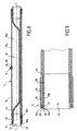
- This shutter position of the flexible hose is shown in Figure 8.
- the elasticity of the inner pipe and possibly the action of the fluid conveyed allow the inner pipe 14 to recover its initial geometry, corresponding to the open position of the flexible pipe with its integral passage. If applicable, the return of the inner pipe in its initial position can be improved or ensured by applying the vacuum at the valve to remove under vacuum the fluid present in the separation zone.
- the method according to the invention consists in manufacturing simultaneously two superimposed pipes, perfectly concentric, but separated by a separation zone.
- the flexible pipe 5 is made on a mandrel which will be passed twice in a machine known from the prior art, a machine of a first type, including making towers, or a machine of a second type, comprising extrusion lines combined with braiding or wrapping machines equipped with a tape head.
- a machine of a first type including making towers, or a machine of a second type, comprising extrusion lines combined with braiding or wrapping machines equipped with a tape head.
- the release pad is constituted by a plastic film, for example a polyester film, which will be suitable for a majority of the elastomeric materials used.
- the pose of the interlayer can also consist of laying a textile layer saturated, completely separating the two pipes, having a low resistance to tearing shear and can be constituted by different existing non-woven products, or to apply a whitewash containing a anti-stick substance.
- This whitewash can be made from diluted silicone blends commonly used to prevent the pipes to stick to the garment mandrels during the operation of vulcanization.
- the laying is carried out of the second intermediate tube 10, of the second reinforcement armature 11 and the outer coating 12.
- the plastic film prevents the adhesion of the two intermediate tubes.
- the inner tube 6, the first reinforcing frame 7 and the first intermediate tube 8 are connected to each other and form the inner pipe 14, and the second intermediate pipe 10, the second reinforcing armature 11 and inner lining 12 bind between them and form the outer pipe 15. It is also possible to use a machine of the aforementioned second type, equipped with a number sufficient reinforcement reinforcement heads to allow the manufacture of the flexible pipe in a single pass.
- the hose is cut to the desired length.
- the length of the flexible hose will be defined in the diameter of the pipe and its structure, within a range of 3 to 15 times the inside diameter.
- a spreader tool 30 is then introduced between the inner pipe and the outer pipe, plus between the intermediate tubes, to allow on the one hand the drilling from the outside of a cylindrical hole 25 in the outer pipe, know through the outer liner, the second reinforcement frame and the second intermediate tube, and possibly the plastic film forming the interlayer, without damaging the inner pipe, and other part of the introduction of the valve 21 between the two intermediate tubes, to lodge it in the hole made.
- the spacer tool 30 consists of of a gutter 31 presenting a first part 32 starting from a end 33 of flat cross section which evolves gradually to take a semicircular general shape.
- This first part 32 with evolutionary cross-section extends by a second part 34 of semi-circular general shape, which ends with a second end 35 of circular cross section.
- the second part for example a cross section extending on an angle between 170 and 200 °.
- the gutter 31 has a hole 36 through which the axis 37 is disposed along the longitudinal plane P of the gutter, perpendicular to the second circular end 35 and slightly offset from this circular end. This circular end 35 and drilling allow the assembly of a tool insertion device for inserting the spreader tool between the pipes inside and outside.
- this insertion tool includes a tubular body adapted to be fitted into the circular end 35 and having a pin inserted into the bore 36.
- This spreader tool 30 can be made from an aluminum tube, by performing different cuts, the different sharp edges from the cuts being blotted to avoid any damage to the inner and outside.
- the spacer tool 30 is progressively inserted by its first end 33 between the inner pipe 14 and the outer pipe 15 for remove the two pipes from each other by deforming the inner pipe, such as shown in Figures 4A and 4B.
- the first part 32 of the tool spreader allows the gradual introduction of the tool between the two pipes, while its second part 34 allows to separate from each other the two pipes.
- the cylindrical hole 25 can then be made on the outer pipe and the valve 21 can then be housed in the hole in passing through the gutter forming the spreader tool. Fixing the valve is then made by screwing a nut 26 on the outer part of the valve, the counter plate 23 bearing against the inner surface 15b outside pipe. Once the valve is in place and the spreader tool removed, the inner pipe 14 returns to its original position thanks to its own elasticity, as shown in Figure 5.
- a bore 28 is then made at each end of the inner pipe and tubing 18 is fitted slightly in force in the bore.
- the outer skirts 19 are then crimped onto the pipe flexible. They are secured longitudinally to the tubings 18 by intermediate of the elastic ring 20.
- the skirt is fitted without forcing on the outer pipe, and the tubing, after introduction without forcing into the inner pipe, is forcibly expanded by means of a dudgeon so as to compress the inner and outer pipes against the outer skirt which, in this case, does not deform. This operation is known as dudonnage.
- This game does not allow the use simple connection methods because when you want to compress the outer pipe on the inner pipe and the pipe, the outer pipe deforms by forming folds that prevent the obtaining of a correct sealing.
- this perfect dimensional fit allows to benefit from the contribution of the two reinforcement frames with a very close performance, for the resistance of the hose to the pressure of the fluid conveyed, in particular for reinforcing reinforcements including steel cables, including elongation under forward tension rupture is very weak.
- the flexible hose according to the invention incorporating a function of shutoff valve of the fluid carried, can be used in different areas of application, especially in all areas use of flexible hose lines made of reinforced elastomers.
- the hose was manufactured on a 40 meter mandrel.
- the pipe was then cut into a 1 meter piece and the spacer tool, shown in Figures 6A-6C, was used to make a 16 mm diameter hole and insert the valve shown in Figures 7A-7C.
- the ends of the flexible pipe were then assembled by the assembly system 17, as previously described.
- the hose being empty, the separation zone between the intermediate tubes was pressurized.
- a complete closure of the hose was obtained for an inflation pressure of 3.10 5 Pa.
- Several cycles were performed and allowed to verify a correct repositioning of the inner pipe. Even in the absence of back pressure in the flexible pipe, the inner pipe resumes its proper place under the effect of its own elasticity.
- the flexible pipe is connected to the end of a line of conventional flexible concrete spreading pipes, and serves to stop the gravity flow of the concrete contained in the spreading boom, during the phases of Maneuvering the spreading boom between pumping operations.
- the main concrete circulation pump with a maximum pressure of 80 ⁇ 10 5 Pa, is stopped and the closure of the passage of the flexible pipe according to the invention is carried out by injecting compressed air at 8 ⁇ 10 5 Pa. by the valve.
- the separating interlayer extends at least up to one of the ends of the hose, at least after the operation of cutting, to perform the installation of the valve. It is of course possible to provide a separator interlayer that does not extend to the ends of the hose and perform a step of setting place the valve on the outer pipe, before the vulcanization step.
- the flexible pipe includes one or more separating tabs covering only partially the first intermediate tube.
- two separator spacers 109a, 109b are arranged between the two pipes so as to preserve two longitudinal zones 100a, 100b diametrically opposite no covered by interleaves, extending the entire length of the pipe flexible. Both spacers cover most of the pipe interior, more precisely the first intermediate tube of said pipe inside, each longitudinal link zone 100a, 100b no covered with a cross-section extending over a sector angular for example between 5 ° and 20 °.
- a valve is assembled at the level of each zone of peeling off.
- a separating interlayer 209 is disposed between the inner pipe 214 and the outer pipe 215 forming the flexible pipe 205, so as to maintain a longitudinal zone of link 200 not covered by the interlayer, extending over the entire length of the flexible hose.
- the interlayer covers most of the first intermediate pipe of said inner pipe, the uncoated zone having a cross-section extending over an angular sector less than 180 °, for example between 110 and 70 °, for example from the order of 90 °.
- the pipe inside and the outer pipe will adhere to each other at the level of the uncovered area and a detachment zone, extending over a angular sector between 290 ° and 250 °, will be formed.
- the particular zones of separation allow better to control the deformation of the inner pipe to close the passage 13.
- the connection between the two pipes at the level of the non overlapped avoids longitudinal displacement of the inner pipes and outside the one with respect to the other during the crimping operation of the external skirts 19.
Landscapes
- Engineering & Computer Science (AREA)
- General Engineering & Computer Science (AREA)
- Mechanical Engineering (AREA)
- Rigid Pipes And Flexible Pipes (AREA)
- Check Valves (AREA)
- Exhaust Silencers (AREA)
Description
- un premier tube interne élastomère, éventuellement une première armature de renfort et un premier tube intermédiaire, formant le tuyau intérieur précité,
- l'intercalaire de décollement,
- un deuxième tube intermédiaire élastomère, éventuellement une armature de renfort et une couche de revêtement externe élastomère, formant le tuyau extérieur précité.
- une étape de réalisation d'un tuyau intérieur en élastomère cru,
- une étape de pose d'au moins un intercalaire de décollement sur ledit tube intérieur,
- une étape de réalisation d'un tuyau extérieur en élastomère cru sur ledit intercalaire de décollement,
- une étape de cuisson simultanée du tuyau intérieur et du tuyau extérieur,
- une étape éventuelle de découpe du tuyau flexible à la longueur souhaitée,
- la figure 1 représente une vue en perspective partielle et en coupe d'un tuyau flexible de l'art antérieur ;
- la figure 2 représente une vue en perspective partielle et en coupe d'un tuyau flexible selon la présente invention ;
- la figure 3A représente une vue en coupe transversale du tuyau flexible de la figure 2 avant sa vulcanisation ;
- les figures 3B et 3C représentent des vues en coupe transversale d'un tuyau flexible, avant sa vulcanisation, selon deux variantes de réalisation ;
- la figure 4A représente une vue en coupe longitudinale d'un tuyau flexible après sa vulcanisation, illustrant l'étape de mise en place de la valve au moyen d'un outil écarteur ;
- la figure 4B représente une vue en coupe transversale du tuyau flexible selon le plan IVB de la figure 4A ;
- la figure 5A représente une vue en coupe longitudinale du tuyau flexible de la figure 1 après la mise en place de la valve ;
- la figure 5B représente une vue en coupe transversale du tuyau flexible selon le plan VB de la figure 5A ;
- les figures 6A, 6B, 6C représentent respectivement une vue en perspective, une vue de dessus et une vue de côté d'un outil écarteur destiné à être utilisé pour l'étape de mise en place de la valve ;
- les figures 7A et 7C représentent respectivement une vue de côté, et une vue de dessus d'une valve avant sa mise en place sur le tuyau flexible ;
- la figure 7B représente une vue en coupe de la valve selon le plan VIIB de la figure 7A;
- la figure 8 représente une vue en coupe longitudinale du tuyau flexible selon l'invention en position d'obturation ; et,
- la figure 9 représente un agrandissement d'une extrémité du tuyau flexible de la figure 8, illustrant le système d'assemblage du tuyau flexible.
- un tube interne 6 en caoutchouc naturel renforcé, résistant à l'abrasion, d'une épaisseur de 6 mm, et de 125 mm de diamètre intérieur ;
- une première et deuxième armature de renfort 7, 11, chacune constituée par deux nappes de câbles acier guipées à +54,7° et -54,7°, et noyées dans du caoutchouc naturel, le câble choisi présente une vie de fatigue en flexion très élevée, démontrée par une utilisation dans la fabrication de pneumatiques pour véhicules poids lourds. Il est laitonné, et l'élastomère en contact est formulé pour obtenir une parfaite adhérence de l'élastomère sur l'acier après vulcanisation. L'épaisseur totale de chaque armature de renfort est de 4 mm;
- un premier et deuxième tube intermédiaire 8, 10 en caoutchouc naturel, chacun d'une épaisseur de 2 mm ;
- un intercalaire de décollement en film polyester d'une épaisseur de 0,1 mm ;
- un revêtement externe 12 en caoutchouc naturel renforcé résistant à l'abrasion d'une épaisseur de 3 mm.
Claims (10)
- Tuyau flexible (5) destiné à transporter un fluide, caractérisé par le fait qu'il comprend un tuyau intérieur flexible (14) et un tuyau extérieur flexible (15) disposés concentriquement par rapport à l'axe longitudinal (L) du tuyau flexible, la surface interne du tuyau intérieur définissant le passage (13) du tuyau flexible pour le fluide à transporter, au moins un intercalaire de décollement (9) intercalé entre le tuyau intérieur (14) et le tuyau extérieur (15) définissant une zone de décollement longitudinale (16) où les deux tuyaux ne sont pas liés l'un à l'autre, ladite zone de décollement présentant une section transversale qui s'étend sur une majeure partie de l'interface à la périphérie entre le tuyau intérieur et le tuyau extérieur, le tuyau extérieur comporte au moins une ouverture (25) débouchant dans ladite zone de décollement, destinée à permettre l'injection ou l'éjection d'un fluide sous pression dans ladite zone de décollement afin de déformer élastiquement le tuyau intérieur et d'obturer ou libérer respectivement le passage du tuyau flexible.
- Tuyau flexible (5) selon la revendication 1, caractérisé par le fait qu'il comprend, disposés radialement de l'intérieur vers l'extérieur par rapport à l'axe longitudinal (L) du tuyau flexible,un premier tube interne élastomère (6), éventuellement une première armature de renfort (7) et un premier tube intermédiaire (8), formant le tuyau intérieur (14) précité,l'intercalaire de décollement (9),un deuxième tube intermédiaire élastomère (10), éventuellement une armature de renfort (11) et une couche de revêtement externe élastomère (12), formant le tuyau extérieur précité.
- Tuyau flexible (5) selon la revendication 2, caractérisé par le fait que l'intercalaire de décollement (9) est constitué par un film plastique non adhérent aux élastomères et/ou une substance anti-collante et/ou une couche textile saturée, ayant une basse résistance à la déchirure au cisaillement.
- Tuyau flexible (5) selon l'une des revendications 1 à 3, caractérisé par le fait que l'intercalaire de décollement (9) s'étend jusqu'à au moins l'une des extrémités du tuyau flexible, ladite extrémité étant munie d'un système d'assemblage (17) apte à serrer les extrémités des tuyaux intérieur et extérieur pour assurer l'étanchéité de la zone de décollement (16).
- Tuyau flexible (5) selon la revendication 4, caractérisé par le fait que le système d'assemblage (17) comprend une tubulure (18) emmanchée dans le tuyau intérieur (14) et des moyens de serrage (19) venant contre la surface externe du tuyau flexible et aptes à serrer les extrémités des tuyaux intérieur et extérieur contre la tubulure pour les assembler hermétiquement.
- Tuyau flexible (5) selon la revendication 5, caractérisé par le fait que la tubulure (18) à l'extrémité du tuyau flexible présente une partie externe (18a) permettant d'assembler les moyens de serrage (19) à la tubulure et/ou destinée au raccordement du tuyau flexible à une ligne de transport de fluide.
- Tuyau flexible (5, 105, 205) selon l'une des revendications précédentes, caractérisé par le fait qu'il comprend un seul intercalaire de décollement (9) présentant une section transversale elliptique, de sorte que le tuyau intérieur (14) et le tuyau extérieur (15) sont séparés entièrement l'un de l'autre par ledit intercalaire de décollement, et/ou deux intercalaires de décollement (109a, 109b) séparés par deux zones longitudinales de liaison (100a, 100b) diamétralement opposées où le tuyau intérieur (114) et le tuyau extérieur (115) adhèrent l'un à l'autre, chaque zone longitudinale ayant une section transversale dont le secteur angulaire est compris entre 5° et 20°, et/ou un seul intercalaire de décollement (209) présentant une section transversale s'étendant sur un angle compris entre 290 et 250°, le tuyau intérieur (214) et le tuyau extérieur (215) adhérant l'un à l'autre sur une zone longitudinale de liaison (200) présentant une section transversale s'étendant sur un angle compris entre 110 et 70°.
- Tuyau flexible (5) selon l'une des revendications précédentes, caractérisé par le fait que le tuyau extérieur (14) comprend au moins une valve (21) disposée dans ladite ouverture (25) du tuyau extérieur et destinée à être raccordée à un tuyau d'alimentation de fluide sous pression.
- Procédé de fabrication d'un tuyau flexible (5) selon l'une des revendications 1 à 8, caractérisé par le fait qu'il comprend successivement :ledit procédé comprenant en outre une étape de réalisation d'au moins une ouverture (25) à travers le tuyau extérieur au niveau dudit intercalaire.une étape de réalisation d'un tuyau intérieur (14) en élastomère cru,une étape de pose d'au moins un intercalaire de décollement (9) sur ledit tube intérieur,une étape de réalisation d'un tuyau extérieur (15) en élastomère cru sur ledit intercalaire de décollement,une étape de cuisson simultanée du tuyau intérieur et du tuyau extérieur,une étape éventuelle de découpe du tuyau flexible à la longueur souhaitée,
- Procédé selon la revendication 9, caractérisé par le fait que l'étape de pose de l'intercalaire de décollement (9) consiste à poser un intercalaire de décollement de sorte qu'il s'étende au moins jusqu'à l'une des extrémités des tuyaux intérieur (14) et extérieur (15), l'étape de réalisation d'une ouverture consiste en la mise en place d'une valve (21) à travers le tuyau extérieur, ladite mise en place de la valve consistant à écarter les tuyaux intérieur (14) et extérieur (15) l'un de l'autre en déformant le tuyau intérieur au moyen d'un outil écarteur (30) inséré entre les tuyaux intérieur et extérieur par leurs extrémités précitées, à réaliser un trou sur le tuyau extérieur écarté du tuyau intérieur, à insérer une valve dans ledit trou en passant entre les deux tuyaux écartés et à fixer ladite valve au tuyau extérieur, ledit procédé comprenant une étape d'assemblage hermétique desdites extrémités des tuyaux extérieur (15) et intérieur (14).
Applications Claiming Priority (2)
| Application Number | Priority Date | Filing Date | Title |
|---|---|---|---|
| FR0104500 | 2001-04-03 | ||
| FR0104500A FR2822923B1 (fr) | 2001-04-03 | 2001-04-03 | Tuyau flexible integrant une fonction de vanne et son procede de fabrication |
Publications (2)
| Publication Number | Publication Date |
|---|---|
| EP1248030A1 EP1248030A1 (fr) | 2002-10-09 |
| EP1248030B1 true EP1248030B1 (fr) | 2005-05-25 |
Family
ID=8861873
Family Applications (1)
| Application Number | Title | Priority Date | Filing Date |
|---|---|---|---|
| EP02290567A Expired - Lifetime EP1248030B1 (fr) | 2001-04-03 | 2002-03-07 | Tuyau flexible intégrant une fonction de vanne et son procédé de fabrication |
Country Status (5)
| Country | Link |
|---|---|
| EP (1) | EP1248030B1 (fr) |
| AT (1) | ATE296424T1 (fr) |
| DE (1) | DE60204257T2 (fr) |
| ES (1) | ES2239206T3 (fr) |
| FR (1) | FR2822923B1 (fr) |
Family Cites Families (3)
| Publication number | Priority date | Publication date | Assignee | Title |
|---|---|---|---|---|
| FR1513484A (fr) * | 1967-01-03 | 1968-02-16 | Houilleres Bassin Du Nord | Dispositif limiteur de pression à obturateur commandé par fluide |
| FR2575538B3 (fr) * | 1984-12-31 | 1987-07-24 | Fact Anal Scp | Dispositif anti-pollution inserable dans une canalisation de distribution d'eau |
| GB9006025D0 (en) * | 1990-03-16 | 1990-05-09 | Lucas Ind Plc | Hose clamp device |
-
2001
- 2001-04-03 FR FR0104500A patent/FR2822923B1/fr not_active Expired - Fee Related
-
2002
- 2002-03-07 ES ES02290567T patent/ES2239206T3/es not_active Expired - Lifetime
- 2002-03-07 EP EP02290567A patent/EP1248030B1/fr not_active Expired - Lifetime
- 2002-03-07 DE DE60204257T patent/DE60204257T2/de not_active Expired - Fee Related
- 2002-03-07 AT AT02290567T patent/ATE296424T1/de not_active IP Right Cessation
Also Published As
| Publication number | Publication date |
|---|---|
| DE60204257T2 (de) | 2006-01-26 |
| ATE296424T1 (de) | 2005-06-15 |
| DE60204257D1 (de) | 2005-06-30 |
| FR2822923A1 (fr) | 2002-10-04 |
| FR2822923B1 (fr) | 2003-08-01 |
| EP1248030A1 (fr) | 2002-10-09 |
| ES2239206T3 (es) | 2005-09-16 |
Similar Documents
| Publication | Publication Date | Title |
|---|---|---|
| EP0545838A1 (fr) | Tube en matériau composite pour l'industrie pétrolière et procédé de fabrication d'un tel tube | |
| EP3014157A1 (fr) | Embout de connexion d'une conduite flexible, conduite flexible et procédé associés | |
| EP2185851B1 (fr) | Procédé de réalisation d'un raccord de conduite | |
| EP3286474A1 (fr) | Procédé de réalisation d'une étanchéité dans un embout d'une conduite flexible comprenant une gaine de pression | |
| EP3692295B1 (fr) | Embout de fixation d'une conduite flexible, conduite flexible et procédé associés | |
| EP0441701B1 (fr) | Structure tubulaire souple comportant une armature de renfort | |
| EP1337780B1 (fr) | Tuyau flexible a bride de raccordement et procede d'obtention d'un tel tuyau | |
| FR3046210A1 (fr) | Embout de connexion d'une ligne flexible, ligne flexible et procede de montage associes | |
| WO2001050059A1 (fr) | Dispositif de raccordement pour deux tuyaux en materiau composite a base de matiere thermoplastique | |
| FR2571459A3 (fr) | Ressort pneumatique comprenant deux elements relies par une membrane flexible impermeable aux gaz | |
| EP1293718A2 (fr) | Tuyau coude, produit intermediaire en forme de tuyau rectiligne et procede pour couder ce produit intermediaire | |
| FR3087869A1 (fr) | Dispositif de connexion pour fluide biopharmaceutique et procede de connexion fluidique irreversible | |
| EP4423417A1 (fr) | Embout de conduite flexible de transport de fluide, conduite flexible et procédé associé | |
| EP1248030A1 (fr) | Tuyau flexible intégrant une fonction de vanne et son procédé de fabrication | |
| FR2587933A1 (fr) | Procede de realisation de flexibles comportant un ou plusieurs flexibles de derivation lateraux, et flexibles ainsi realises | |
| FR2882419A1 (fr) | Tuyau pour transporter un fluide et procede pour le produire | |
| WO2023247875A1 (fr) | Procédé d'assemblage de tuyaux souples en élastomère et ensemble de tuyaux ainsi assemblés | |
| FR2728049A1 (fr) | Dispositif de raccordement d'une extremite d'un tube en matiere thermoplastique renforcee | |
| EP1010930A1 (fr) | Flexible composite pour le transport de fluide et son procédé de fabrication | |
| FR2680223A1 (fr) | Dispositif d'obturation d'un orifice forme dans la paroi d'une canalisation et ensemble constitue par un tel dispositif et la canalisation. | |
| EP4433735B1 (fr) | Organe de compression pour conduite de transport de fluides munie d'un chemisage interne de protection et methode d'utilisation | |
| EP0196954B1 (fr) | Renforcement de talon de structure tubulaire à armature fractionnable | |
| FR2729206A1 (fr) | Procede pour realiser une liaison entre une piece tubulaire rigide et l'extremite d'un tube souple | |
| EP4209299B1 (fr) | Réservoir comprenant au moins deux parties reliées par une couronne de jonction et des soudures obtenues par un procédé de soudage par friction et procédé de fabrication dudit réservoir | |
| CH696598A5 (fr) | Bride étanche contre les fuites pour raccorder des tuyaux ayant des diamètres extérieurs différents et des extrémités lisses. |
Legal Events
| Date | Code | Title | Description |
|---|---|---|---|
| PUAI | Public reference made under article 153(3) epc to a published international application that has entered the european phase |
Free format text: ORIGINAL CODE: 0009012 |
|
| AK | Designated contracting states |
Kind code of ref document: A1 Designated state(s): AT BE CH CY DE DK ES FI FR GB GR IE IT LI LU MC NL PT SE TR |
|
| AX | Request for extension of the european patent |
Free format text: AL;LT;LV;MK;RO;SI |
|
| 17P | Request for examination filed |
Effective date: 20021125 |
|
| AKX | Designation fees paid |
Designated state(s): AT BE CH CY DE DK ES FI FR GB GR IE IT LI LU MC NL PT SE TR |
|
| GRAP | Despatch of communication of intention to grant a patent |
Free format text: ORIGINAL CODE: EPIDOSNIGR1 |
|
| GRAS | Grant fee paid |
Free format text: ORIGINAL CODE: EPIDOSNIGR3 |
|
| GRAA | (expected) grant |
Free format text: ORIGINAL CODE: 0009210 |
|
| AK | Designated contracting states |
Kind code of ref document: B1 Designated state(s): AT BE CH CY DE DK ES FI FR GB GR IE IT LI LU MC NL PT SE TR |
|
| PG25 | Lapsed in a contracting state [announced via postgrant information from national office to epo] |
Ref country code: AT Free format text: LAPSE BECAUSE OF FAILURE TO SUBMIT A TRANSLATION OF THE DESCRIPTION OR TO PAY THE FEE WITHIN THE PRESCRIBED TIME-LIMIT Effective date: 20050525 Ref country code: FI Free format text: LAPSE BECAUSE OF FAILURE TO SUBMIT A TRANSLATION OF THE DESCRIPTION OR TO PAY THE FEE WITHIN THE PRESCRIBED TIME-LIMIT Effective date: 20050525 Ref country code: IE Free format text: LAPSE BECAUSE OF FAILURE TO SUBMIT A TRANSLATION OF THE DESCRIPTION OR TO PAY THE FEE WITHIN THE PRESCRIBED TIME-LIMIT Effective date: 20050525 Ref country code: TR Free format text: LAPSE BECAUSE OF FAILURE TO SUBMIT A TRANSLATION OF THE DESCRIPTION OR TO PAY THE FEE WITHIN THE PRESCRIBED TIME-LIMIT Effective date: 20050525 |
|
| REG | Reference to a national code |
Ref country code: GB Ref legal event code: FG4D Free format text: NOT ENGLISH |
|
| REG | Reference to a national code |
Ref country code: CH Ref legal event code: EP |
|
| REG | Reference to a national code |
Ref country code: IE Ref legal event code: FG4D Free format text: LANGUAGE OF EP DOCUMENT: FRENCH |
|
| REF | Corresponds to: |
Ref document number: 60204257 Country of ref document: DE Date of ref document: 20050630 Kind code of ref document: P |
|
| GBT | Gb: translation of ep patent filed (gb section 77(6)(a)/1977) |
Effective date: 20050801 |
|
| PG25 | Lapsed in a contracting state [announced via postgrant information from national office to epo] |
Ref country code: GR Free format text: LAPSE BECAUSE OF FAILURE TO SUBMIT A TRANSLATION OF THE DESCRIPTION OR TO PAY THE FEE WITHIN THE PRESCRIBED TIME-LIMIT Effective date: 20050825 Ref country code: SE Free format text: LAPSE BECAUSE OF FAILURE TO SUBMIT A TRANSLATION OF THE DESCRIPTION OR TO PAY THE FEE WITHIN THE PRESCRIBED TIME-LIMIT Effective date: 20050825 Ref country code: DK Free format text: LAPSE BECAUSE OF FAILURE TO SUBMIT A TRANSLATION OF THE DESCRIPTION OR TO PAY THE FEE WITHIN THE PRESCRIBED TIME-LIMIT Effective date: 20050825 |
|
| REG | Reference to a national code |
Ref country code: ES Ref legal event code: FG2A Ref document number: 2239206 Country of ref document: ES Kind code of ref document: T3 |
|
| PG25 | Lapsed in a contracting state [announced via postgrant information from national office to epo] |
Ref country code: PT Free format text: LAPSE BECAUSE OF FAILURE TO SUBMIT A TRANSLATION OF THE DESCRIPTION OR TO PAY THE FEE WITHIN THE PRESCRIBED TIME-LIMIT Effective date: 20051027 |
|
| REG | Reference to a national code |
Ref country code: IE Ref legal event code: FD4D |
|
| PG25 | Lapsed in a contracting state [announced via postgrant information from national office to epo] |
Ref country code: CH Free format text: LAPSE BECAUSE OF NON-PAYMENT OF DUE FEES Effective date: 20060331 Ref country code: LU Free format text: LAPSE BECAUSE OF NON-PAYMENT OF DUE FEES Effective date: 20060331 Ref country code: MC Free format text: LAPSE BECAUSE OF NON-PAYMENT OF DUE FEES Effective date: 20060331 Ref country code: LI Free format text: LAPSE BECAUSE OF NON-PAYMENT OF DUE FEES Effective date: 20060331 |
|
| PLBE | No opposition filed within time limit |
Free format text: ORIGINAL CODE: 0009261 |
|
| STAA | Information on the status of an ep patent application or granted ep patent |
Free format text: STATUS: NO OPPOSITION FILED WITHIN TIME LIMIT |
|
| 26N | No opposition filed |
Effective date: 20060228 |
|
| REG | Reference to a national code |
Ref country code: CH Ref legal event code: PL |
|
| PGFP | Annual fee paid to national office [announced via postgrant information from national office to epo] |
Ref country code: BE Payment date: 20080411 Year of fee payment: 7 |
|
| PG25 | Lapsed in a contracting state [announced via postgrant information from national office to epo] |
Ref country code: CY Free format text: LAPSE BECAUSE OF FAILURE TO SUBMIT A TRANSLATION OF THE DESCRIPTION OR TO PAY THE FEE WITHIN THE PRESCRIBED TIME-LIMIT Effective date: 20050525 |
|
| PGFP | Annual fee paid to national office [announced via postgrant information from national office to epo] |
Ref country code: ES Payment date: 20090323 Year of fee payment: 8 |
|
| PGFP | Annual fee paid to national office [announced via postgrant information from national office to epo] |
Ref country code: NL Payment date: 20090227 Year of fee payment: 8 |
|
| PGFP | Annual fee paid to national office [announced via postgrant information from national office to epo] |
Ref country code: GB Payment date: 20090303 Year of fee payment: 8 |
|
| PGFP | Annual fee paid to national office [announced via postgrant information from national office to epo] |
Ref country code: DE Payment date: 20090312 Year of fee payment: 8 Ref country code: IT Payment date: 20090319 Year of fee payment: 8 |
|
| BERE | Be: lapsed |
Owner name: *TRELLEBORG INDUSTRIE Effective date: 20090331 |
|
| PGFP | Annual fee paid to national office [announced via postgrant information from national office to epo] |
Ref country code: FR Payment date: 20090227 Year of fee payment: 8 |
|
| PG25 | Lapsed in a contracting state [announced via postgrant information from national office to epo] |
Ref country code: BE Free format text: LAPSE BECAUSE OF NON-PAYMENT OF DUE FEES Effective date: 20090331 |
|
| REG | Reference to a national code |
Ref country code: NL Ref legal event code: V1 Effective date: 20101001 |
|
| GBPC | Gb: european patent ceased through non-payment of renewal fee |
Effective date: 20100307 |
|
| REG | Reference to a national code |
Ref country code: FR Ref legal event code: ST Effective date: 20101130 |
|
| PG25 | Lapsed in a contracting state [announced via postgrant information from national office to epo] |
Ref country code: FR Free format text: LAPSE BECAUSE OF NON-PAYMENT OF DUE FEES Effective date: 20100331 Ref country code: NL Free format text: LAPSE BECAUSE OF NON-PAYMENT OF DUE FEES Effective date: 20101001 |
|
| PG25 | Lapsed in a contracting state [announced via postgrant information from national office to epo] |
Ref country code: DE Free format text: LAPSE BECAUSE OF NON-PAYMENT OF DUE FEES Effective date: 20101001 |
|
| PG25 | Lapsed in a contracting state [announced via postgrant information from national office to epo] |
Ref country code: IT Free format text: LAPSE BECAUSE OF NON-PAYMENT OF DUE FEES Effective date: 20100307 Ref country code: GB Free format text: LAPSE BECAUSE OF NON-PAYMENT OF DUE FEES Effective date: 20100307 |
|
| REG | Reference to a national code |
Ref country code: ES Ref legal event code: FD2A Effective date: 20110415 |
|
| PG25 | Lapsed in a contracting state [announced via postgrant information from national office to epo] |
Ref country code: ES Free format text: LAPSE BECAUSE OF NON-PAYMENT OF DUE FEES Effective date: 20110404 |
|
| PG25 | Lapsed in a contracting state [announced via postgrant information from national office to epo] |
Ref country code: ES Free format text: LAPSE BECAUSE OF NON-PAYMENT OF DUE FEES Effective date: 20100308 |