EP1247971A2 - Control system and method for an internal combustion engine - Google Patents
Control system and method for an internal combustion engine Download PDFInfo
- Publication number
- EP1247971A2 EP1247971A2 EP02005521A EP02005521A EP1247971A2 EP 1247971 A2 EP1247971 A2 EP 1247971A2 EP 02005521 A EP02005521 A EP 02005521A EP 02005521 A EP02005521 A EP 02005521A EP 1247971 A2 EP1247971 A2 EP 1247971A2
- Authority
- EP
- European Patent Office
- Prior art keywords
- engine
- control mechanism
- compression ratio
- lift
- ignition timing
- Prior art date
- Legal status (The legal status is an assumption and is not a legal conclusion. Google has not performed a legal analysis and makes no representation as to the accuracy of the status listed.)
- Granted
Links
- 238000002485 combustion reaction Methods 0.000 title claims abstract description 50
- 238000000034 method Methods 0.000 title claims abstract description 20
- 230000006835 compression Effects 0.000 claims abstract description 105
- 238000007906 compression Methods 0.000 claims abstract description 105
- 230000007246 mechanism Effects 0.000 claims abstract description 82
- 230000003197 catalytic effect Effects 0.000 claims description 11
- 230000004044 response Effects 0.000 claims description 11
- 230000003247 decreasing effect Effects 0.000 claims description 4
- 230000010355 oscillation Effects 0.000 description 20
- 239000003054 catalyst Substances 0.000 description 15
- 230000000694 effects Effects 0.000 description 10
- 238000010792 warming Methods 0.000 description 7
- 230000001276 controlling effect Effects 0.000 description 6
- 239000000446 fuel Substances 0.000 description 6
- 239000000203 mixture Substances 0.000 description 6
- 239000002826 coolant Substances 0.000 description 5
- 238000010586 diagram Methods 0.000 description 5
- 230000000979 retarding effect Effects 0.000 description 5
- 230000001133 acceleration Effects 0.000 description 3
- 238000000889 atomisation Methods 0.000 description 3
- 230000008901 benefit Effects 0.000 description 2
- 230000008859 change Effects 0.000 description 2
- 238000006243 chemical reaction Methods 0.000 description 2
- 230000001737 promoting effect Effects 0.000 description 2
- 238000005086 pumping Methods 0.000 description 2
- 235000013290 Sagittaria latifolia Nutrition 0.000 description 1
- 230000015572 biosynthetic process Effects 0.000 description 1
- 235000015246 common arrowhead Nutrition 0.000 description 1
- 230000003111 delayed effect Effects 0.000 description 1
- 230000002542 deteriorative effect Effects 0.000 description 1
- 238000005516 engineering process Methods 0.000 description 1
- 230000006872 improvement Effects 0.000 description 1
- 238000004519 manufacturing process Methods 0.000 description 1
- 238000012986 modification Methods 0.000 description 1
- 230000004048 modification Effects 0.000 description 1
- 230000003647 oxidation Effects 0.000 description 1
- 238000007254 oxidation reaction Methods 0.000 description 1
- 230000033116 oxidation-reduction process Effects 0.000 description 1
- 238000000746 purification Methods 0.000 description 1
- 230000001603 reducing effect Effects 0.000 description 1
- 230000009467 reduction Effects 0.000 description 1
- 230000001105 regulatory effect Effects 0.000 description 1
- 239000000126 substance Substances 0.000 description 1
- 230000007704 transition Effects 0.000 description 1
- 238000011144 upstream manufacturing Methods 0.000 description 1
Images


Classifications
-
- F—MECHANICAL ENGINEERING; LIGHTING; HEATING; WEAPONS; BLASTING
- F02—COMBUSTION ENGINES; HOT-GAS OR COMBUSTION-PRODUCT ENGINE PLANTS
- F02D—CONTROLLING COMBUSTION ENGINES
- F02D13/00—Controlling the engine output power by varying inlet or exhaust valve operating characteristics, e.g. timing
- F02D13/02—Controlling the engine output power by varying inlet or exhaust valve operating characteristics, e.g. timing during engine operation
- F02D13/0223—Variable control of the intake valves only
- F02D13/0226—Variable control of the intake valves only changing valve lift or valve lift and timing
- F02D13/023—Variable control of the intake valves only changing valve lift or valve lift and timing the change of valve timing is caused by the change in valve lift, i.e. both valve lift and timing are functionally related
-
- F—MECHANICAL ENGINEERING; LIGHTING; HEATING; WEAPONS; BLASTING
- F01—MACHINES OR ENGINES IN GENERAL; ENGINE PLANTS IN GENERAL; STEAM ENGINES
- F01L—CYCLICALLY OPERATING VALVES FOR MACHINES OR ENGINES
- F01L1/00—Valve-gear or valve arrangements, e.g. lift-valve gear
- F01L1/34—Valve-gear or valve arrangements, e.g. lift-valve gear characterised by the provision of means for changing the timing of the valves without changing the duration of opening and without affecting the magnitude of the valve lift
-
- F—MECHANICAL ENGINEERING; LIGHTING; HEATING; WEAPONS; BLASTING
- F01—MACHINES OR ENGINES IN GENERAL; ENGINE PLANTS IN GENERAL; STEAM ENGINES
- F01L—CYCLICALLY OPERATING VALVES FOR MACHINES OR ENGINES
- F01L13/00—Modifications of valve-gear to facilitate reversing, braking, starting, changing compression ratio, or other specific operations
- F01L13/0015—Modifications of valve-gear to facilitate reversing, braking, starting, changing compression ratio, or other specific operations for optimising engine performances by modifying valve lift according to various working parameters, e.g. rotational speed, load, torque
- F01L13/0021—Modifications of valve-gear to facilitate reversing, braking, starting, changing compression ratio, or other specific operations for optimising engine performances by modifying valve lift according to various working parameters, e.g. rotational speed, load, torque by modification of rocker arm ratio
- F01L13/0026—Modifications of valve-gear to facilitate reversing, braking, starting, changing compression ratio, or other specific operations for optimising engine performances by modifying valve lift according to various working parameters, e.g. rotational speed, load, torque by modification of rocker arm ratio by means of an eccentric
-
- F—MECHANICAL ENGINEERING; LIGHTING; HEATING; WEAPONS; BLASTING
- F02—COMBUSTION ENGINES; HOT-GAS OR COMBUSTION-PRODUCT ENGINE PLANTS
- F02B—INTERNAL-COMBUSTION PISTON ENGINES; COMBUSTION ENGINES IN GENERAL
- F02B41/00—Engines characterised by special means for improving conversion of heat or pressure energy into mechanical power
- F02B41/02—Engines with prolonged expansion
- F02B41/04—Engines with prolonged expansion in main cylinders
-
- F—MECHANICAL ENGINEERING; LIGHTING; HEATING; WEAPONS; BLASTING
- F02—COMBUSTION ENGINES; HOT-GAS OR COMBUSTION-PRODUCT ENGINE PLANTS
- F02B—INTERNAL-COMBUSTION PISTON ENGINES; COMBUSTION ENGINES IN GENERAL
- F02B75/00—Other engines
- F02B75/04—Engines with variable distances between pistons at top dead-centre positions and cylinder heads
- F02B75/048—Engines with variable distances between pistons at top dead-centre positions and cylinder heads by means of a variable crank stroke length
-
- F—MECHANICAL ENGINEERING; LIGHTING; HEATING; WEAPONS; BLASTING
- F02—COMBUSTION ENGINES; HOT-GAS OR COMBUSTION-PRODUCT ENGINE PLANTS
- F02D—CONTROLLING COMBUSTION ENGINES
- F02D13/00—Controlling the engine output power by varying inlet or exhaust valve operating characteristics, e.g. timing
- F02D13/02—Controlling the engine output power by varying inlet or exhaust valve operating characteristics, e.g. timing during engine operation
- F02D13/0223—Variable control of the intake valves only
- F02D13/0234—Variable control of the intake valves only changing the valve timing only
- F02D13/0238—Variable control of the intake valves only changing the valve timing only by shifting the phase, i.e. the opening periods of the valves are constant
-
- F—MECHANICAL ENGINEERING; LIGHTING; HEATING; WEAPONS; BLASTING
- F02—COMBUSTION ENGINES; HOT-GAS OR COMBUSTION-PRODUCT ENGINE PLANTS
- F02D—CONTROLLING COMBUSTION ENGINES
- F02D13/00—Controlling the engine output power by varying inlet or exhaust valve operating characteristics, e.g. timing
- F02D13/02—Controlling the engine output power by varying inlet or exhaust valve operating characteristics, e.g. timing during engine operation
- F02D13/0269—Controlling the valves to perform a Miller-Atkinson cycle
-
- F—MECHANICAL ENGINEERING; LIGHTING; HEATING; WEAPONS; BLASTING
- F02—COMBUSTION ENGINES; HOT-GAS OR COMBUSTION-PRODUCT ENGINE PLANTS
- F02D—CONTROLLING COMBUSTION ENGINES
- F02D15/00—Varying compression ratio
-
- F—MECHANICAL ENGINEERING; LIGHTING; HEATING; WEAPONS; BLASTING
- F02—COMBUSTION ENGINES; HOT-GAS OR COMBUSTION-PRODUCT ENGINE PLANTS
- F02D—CONTROLLING COMBUSTION ENGINES
- F02D37/00—Non-electrical conjoint control of two or more functions of engines, not otherwise provided for
- F02D37/02—Non-electrical conjoint control of two or more functions of engines, not otherwise provided for one of the functions being ignition
-
- F—MECHANICAL ENGINEERING; LIGHTING; HEATING; WEAPONS; BLASTING
- F02—COMBUSTION ENGINES; HOT-GAS OR COMBUSTION-PRODUCT ENGINE PLANTS
- F02P—IGNITION, OTHER THAN COMPRESSION IGNITION, FOR INTERNAL-COMBUSTION ENGINES; TESTING OF IGNITION TIMING IN COMPRESSION-IGNITION ENGINES
- F02P5/00—Advancing or retarding ignition; Control therefor
- F02P5/04—Advancing or retarding ignition; Control therefor automatically, as a function of the working conditions of the engine or vehicle or of the atmospheric conditions
- F02P5/045—Advancing or retarding ignition; Control therefor automatically, as a function of the working conditions of the engine or vehicle or of the atmospheric conditions combined with electronic control of other engine functions, e.g. fuel injection
-
- F—MECHANICAL ENGINEERING; LIGHTING; HEATING; WEAPONS; BLASTING
- F02—COMBUSTION ENGINES; HOT-GAS OR COMBUSTION-PRODUCT ENGINE PLANTS
- F02P—IGNITION, OTHER THAN COMPRESSION IGNITION, FOR INTERNAL-COMBUSTION ENGINES; TESTING OF IGNITION TIMING IN COMPRESSION-IGNITION ENGINES
- F02P5/00—Advancing or retarding ignition; Control therefor
- F02P5/04—Advancing or retarding ignition; Control therefor automatically, as a function of the working conditions of the engine or vehicle or of the atmospheric conditions
- F02P5/145—Advancing or retarding ignition; Control therefor automatically, as a function of the working conditions of the engine or vehicle or of the atmospheric conditions using electrical means
- F02P5/15—Digital data processing
- F02P5/1502—Digital data processing using one central computing unit
- F02P5/1506—Digital data processing using one central computing unit with particular means during starting
-
- F—MECHANICAL ENGINEERING; LIGHTING; HEATING; WEAPONS; BLASTING
- F01—MACHINES OR ENGINES IN GENERAL; ENGINE PLANTS IN GENERAL; STEAM ENGINES
- F01L—CYCLICALLY OPERATING VALVES FOR MACHINES OR ENGINES
- F01L13/00—Modifications of valve-gear to facilitate reversing, braking, starting, changing compression ratio, or other specific operations
- F01L13/0015—Modifications of valve-gear to facilitate reversing, braking, starting, changing compression ratio, or other specific operations for optimising engine performances by modifying valve lift according to various working parameters, e.g. rotational speed, load, torque
- F01L13/0063—Modifications of valve-gear to facilitate reversing, braking, starting, changing compression ratio, or other specific operations for optimising engine performances by modifying valve lift according to various working parameters, e.g. rotational speed, load, torque by modification of cam contact point by displacing an intermediate lever or wedge-shaped intermediate element, e.g. Tourtelot
- F01L2013/0073—Modifications of valve-gear to facilitate reversing, braking, starting, changing compression ratio, or other specific operations for optimising engine performances by modifying valve lift according to various working parameters, e.g. rotational speed, load, torque by modification of cam contact point by displacing an intermediate lever or wedge-shaped intermediate element, e.g. Tourtelot with an oscillating cam acting on the valve of the "Delphi" type
-
- F—MECHANICAL ENGINEERING; LIGHTING; HEATING; WEAPONS; BLASTING
- F01—MACHINES OR ENGINES IN GENERAL; ENGINE PLANTS IN GENERAL; STEAM ENGINES
- F01L—CYCLICALLY OPERATING VALVES FOR MACHINES OR ENGINES
- F01L2800/00—Methods of operation using a variable valve timing mechanism
-
- F—MECHANICAL ENGINEERING; LIGHTING; HEATING; WEAPONS; BLASTING
- F02—COMBUSTION ENGINES; HOT-GAS OR COMBUSTION-PRODUCT ENGINE PLANTS
- F02D—CONTROLLING COMBUSTION ENGINES
- F02D41/00—Electrical control of supply of combustible mixture or its constituents
- F02D41/0002—Controlling intake air
- F02D2041/001—Controlling intake air for engines with variable valve actuation
-
- Y—GENERAL TAGGING OF NEW TECHNOLOGICAL DEVELOPMENTS; GENERAL TAGGING OF CROSS-SECTIONAL TECHNOLOGIES SPANNING OVER SEVERAL SECTIONS OF THE IPC; TECHNICAL SUBJECTS COVERED BY FORMER USPC CROSS-REFERENCE ART COLLECTIONS [XRACs] AND DIGESTS
- Y02—TECHNOLOGIES OR APPLICATIONS FOR MITIGATION OR ADAPTATION AGAINST CLIMATE CHANGE
- Y02T—CLIMATE CHANGE MITIGATION TECHNOLOGIES RELATED TO TRANSPORTATION
- Y02T10/00—Road transport of goods or passengers
- Y02T10/10—Internal combustion engine [ICE] based vehicles
- Y02T10/12—Improving ICE efficiencies
-
- Y—GENERAL TAGGING OF NEW TECHNOLOGICAL DEVELOPMENTS; GENERAL TAGGING OF CROSS-SECTIONAL TECHNOLOGIES SPANNING OVER SEVERAL SECTIONS OF THE IPC; TECHNICAL SUBJECTS COVERED BY FORMER USPC CROSS-REFERENCE ART COLLECTIONS [XRACs] AND DIGESTS
- Y02—TECHNOLOGIES OR APPLICATIONS FOR MITIGATION OR ADAPTATION AGAINST CLIMATE CHANGE
- Y02T—CLIMATE CHANGE MITIGATION TECHNOLOGIES RELATED TO TRANSPORTATION
- Y02T10/00—Road transport of goods or passengers
- Y02T10/10—Internal combustion engine [ICE] based vehicles
- Y02T10/40—Engine management systems
Definitions
- the present invention relates to a control system for an internal combustion engine equipped with a compression ratio control mechanism capable of varying a compression ratio, a lift and operation angle control mechanism capable of varying a lift and operation angle of an intake valve, and a phase control mechanism capable of varying a maximum lift phase of an intake valve.
- the present invention further relates to a method for controlling such an internal combustion engine.
- the present invention relates to a technique for improving the exhaust gas purifying efficiency of a spark-ignited internal combustion engine equipped with a catalytic exhaust gas purifier.
- variable valve timing control mechanism that can vary the lift and operation angle of an intake valve simultaneously and continuously as disclosed in Japanese Patent Provisional Publication Nos. 11-107725 and 11-324625.
- the assignee has further proposed a variable valve timing control mechanism that can attain a wide design freedom of the lift characteristics in combination with a phase control mechanism for varying a maximum lift phase.
- an exhaust system of an internal combustion engine is provided with a catalytic exhaust gas purifier made up of an oxidation-reduction catalyst, oxidation catalyst or a reduction catalyst.
- a catalytic exhaust gas purifier made up of an oxidation-reduction catalyst, oxidation catalyst or a reduction catalyst.
- the fundamentals to solving such a problem are how fast the catalyst can reach the temperature at which the catalyst starts conversion.
- the ignition timing is delayed during warming up (i.e., the exhaust gas temperature is elevated by retarding the timing at which combustion starts). This, however, causes a bad influence on the fuel consumption but is widely exercised.
- the ignition timing is retarded largely, there is caused a problem that the combustion becomes unstable and in the worst case a misfire is caused and therefore a large amount of unburnt substances as HC is possibly emitted. Accordingly, for largely retarding the ignition timing, it is indispensable to improve the combustion.
- it is a representative method for improving the combustion under those circumstances to provide the intake port with a swirl control valve for intensifying the gas flow within the cylinder, but this is not always sufficient.
- a control system for an internal combustion engine having a compression ratio control mechanism capable of varying a compression ratio of the engine, an ignition timing control system capable of varying an ignition timing of the engine, and a catalytic exhaust gas purifier disposed in an exhaust system of the engine
- the control system comprising an engine control unit for controlling the compression ratio control mechanism and the ignition timing control system so that the compression ratio is varied depending upon variations of engine rpm, engine load and a warm-up condition of the engine and that when the engine is cold, the ignition timing is retarded largely from an MBT point and the compression ratio is set higher than that obtained when the engine is hot and operated at corresponding engine rpm and engine load.
- an internal combustion engine comprising a compression ratio control mechanism capable of varying a compression ratio of the engine, an ignition timing control system capable of varying an ignition timing of the engine, a catalytic exhaust gas purifier disposed in an exhaust system of the engine and an engine control unit for controlling the compression ratio control mechanism and the ignition timing control system so that the compression ratio is varied depending upon variations of engine rpm, engine load and a warm-up condition of the engine and that when the engine is cold, the ignition timing is retarded largely from an MBT point and the compression ratio is set higher than that obtained when the engine is hot and operated at corresponding engine rpm and engine load.
- a method for controlling an internal combustion engine having a compression ratio control mechanism capable of varying a compression ratio of the engine, an ignition timing control system capable of varying an ignition timing of the engine, and a catalytic exhaust gas purifier disposed in an exhaust system of the engine, the method comprising controlling the compression ratio control mechanism and the ignition timing control system so that the compression ratio is varied depending upon variations of engine rpm, engine load and a warm-up condition of the engine and that when the engine is cold, the ignition timing is retarded largely from an MBT point and the compression ratio is set higher than that obtained when the engine is hot and operated at corresponding engine rpm and engine load.
- an internal combustion engine includes variable valve timing control apparatus 101 for varying intake valve opening and closing timings, compression ratio control mechanism 102 for varying nominal compression ratio E of the engine, ignition timing control system 103 for varying an ignition timing, and catalytic exhaust gas purifier 104 disposed in an exhaust system.
- Variable valve timing control apparatus 101 is shown in an enlarged scale in FIG. 2 and includes lift and operation angle control mechanism 1 for varying a lift and operation angle of intake valve 12 and phase control mechanism for varying a phase of intake valve 12, i.e., a maximum lift phase of intake valve 12 relative to a rotational phase of crankshaft 51.
- Lift and operation angle control mechanism 1 is structurally the same as that disclosed in Japanese Patent Provisional Publication No. 11-107725 which was assigned to the same assignee of this application, so that only brief description will be made thereto hereinafter.
- Lift and operation angle control mechanism 1 includes hollow drive shaft 13 rotatably supported on cylinder head 64 by cam brackets (not shown), eccentric cam 15 force-fitted or otherwise fixedly attached to drive shaft 13, control shaft 16 disposed above and in parallel with drive shaft 13 and rotatably supported on cylinder head 64 by the above described cam brackets, rocker arm 18 mounted on eccentric cam portion 17 of control shaft 16 for oscillation motion, and oscillation cam 20 engaging tappet 19 provided to an upper end portion of intake valve 12.
- Eccentric cam 15 and rocker arm 18 are operatively connected by pivotal link 25, and rocker arm 18 and oscillation cam 20 are operatively connected by connecting rod 26.
- Drive shaft 13 is driven by crankshaft 51 of the engine by way of a timing chain or timing belt (not shown).
- Eccentric cam 15 has a circular external surface the center of which is offset from a rotational axis of drive shaft 13 by a predetermined amount. On the circular external surface is rotatably fitted or mounted annular base portion 25a of pivotal link 25.
- Rocker arm 18 is mounted at a central portion thereof on eccentric cam portion 17 and has an end portion to which protruded arm portion 25b of above described pivotal link 25 is pivotally connected and another end portion to which an upper end portion of connecting rod 26 is pivotally connected.
- Eccentric cam portion17 has a geometric center that is offset from the rotational axis of control shaft 16 so that an axis of oscillation of rocker arm 18 varies depending upon a variation of a rotational position or phase of control shaft 16.
- Oscillation cam 20 is rotatably mounted on drive shaft 13 and has laterally protruded end portion 20a to which a lower end portion of connecting link 26 is pivotally connected.
- Oscillation cam 20 has at its lower side thereof basic circular or dwell surface 24a and cam or lift surface 24b extending from basic circular surface 24a toward above described end portion 20a so as to have a predetermined curved profile.
- Basic circular surface 24a and cam surface 24b are brought into engagement with the upper surface of tappet 19 in response to oscillation of oscillation cam 20.
- basic circular surface 24a serves as a base circle area that regulates an amount of lift to zero.
- oscillation cam 20 is turned or rotated to bring cam surface 24b serving as a lift or rise area into contact with tappet 19, there is caused a lift of intake valve 12 that increases gradually with further rotation of oscillation cam 20.
- a small ramp area between the basic circular area and the lift area is provided a small ramp area.
- Control shaft 16 is constructed so as to be rotatable within a predetermined rotational angle range by being driven by hydraulic, lift and operation angle control actuator 31 installed on an end of control shaft 16 as shown in FIGS. 1 and 2.
- Supply of hydraulic pressure to actuator 31 is performed by first hydraulic pressure controller 32 in response to a control signal from engine control unit (ECU) 33.
- ECU engine control unit
- lift and operation angle control mechanism 1 will now be described.
- Rotation of drive shaft 13 causes pivotal link 25 to move up and down by the operation of eccentric cam 15.
- rocker arm 18 is caused to oscillate.
- This oscillating movement of rocker arm 18 causes oscillation cam 20 to oscillate.
- tappet 19 is caused to move up and down, causing intake valve 19 to open and close.
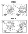
- eccentric cam portion 17 when eccentric cam portion 17 is generally positioned in a higher place as shown in FIG. 3A, i.e., when the geometric center of eccentric cam portion 17 is located above the rotational axis of control shaft 16, rocker arm 18 is bodily moved into a higher place, thus causing end portion 20a of oscillation cam 20 to be moved into a higher position.
- cam surface 24b when oscillation cam 20 is rotated into the initial position, cam surface 24b is caused to incline away from tappet 19.
- basic circular surface 24a is brought into contact with tappet 19 for a longer period
- cam surface 24b is brought into contact with tappet 19 for a shorter period. Accordingly, the amount of lift is small, and an angular range from an opening timing to a closing timing, i.e., the operation angle is reduced.
- eccentric cam portion 17 is generally positioned in a lower place as shown in FIG. 3B, rocker arm 18 is bodily moved into a lower place, thus causing end portion 20a of oscillation cam 20 to move into a lower position.
- cam surface 24b is caused to incline toward tappet 19.
- the place where oscillation cam 20 is brought into contact with tappet 19 changes immediately from basic circular surface 24a to cam surface 24b. Accordingly, the amount of lift becomes larger and the operation angle is enlarged.
- the lift and operation angle characteristics of intake valve 12 can be varied continuously as shown in FIG. 4. Namely, both of the lift and operation angle can be increased and decreased simultaneously and continuously.
- lift and operation angle control mechanism 1 the opening and closing timings are varied so as to be nearly symmetrical with respect to the maximum lift phase, in response to a variation of the lift and operation angle.
- phase control mechanism 2 includes sprocket 35 provided to a front end portion of drive shaft 13, and hydraulic, phase control actuator 36 for rotating sprocket 35 relative to drive shaft 13 within a predetermined angular range.
- Sprocket 35 is drivingly connected to crankshaft 51 by way of the timing chain or timing belt (not shown) so as to be rotatable in timed relation to crankshaft 51.
- Supply of oil pressure to actuator 36 is controlled by second oil pressure controller 37 in response to a signal from engine control unit (ECU) 33.
- ECU engine control unit
- Phase control mechanism 2 is not limited to the hydraulic type but can have various other structures such as one utilizing an electromagnetic actuator.
- Lift and operation angle control mechanism 1 and phase control mechanism 2 can be open-loop controlled by using sensors (not shown) for detecting an actual lift, operation angle and maximum lift phase or can be simply closed-loop controlled in response to an engine operating condition.
- FIG. 6 shows a compression ratio control mechanism 102.
- Compression ratio control mechanism 102 includes crankshaft 51 having a plurality of journal portions 52 and a plurality of crank pins 53. On main bearings (not shown) installed on cylinder block 50 are rotatably supported journal portions 52. Crank pins 53 are offset from journal portions 52 by a predetermined amount. To each crank pin 53 is swingably or pivotally connected lower link 54 serving as a second link.
- Lower link 54 is nearly T-shaped and made up of two separable sections. Nearly at a central portion of lower link 54 and between the separable sections is formed a connecting hole in which crank pin 53 is fitted.
- Upper link 55 serving as a first link is pivotally connected at a lower end to one end of lower link 54 by means of connecting pin 56 and at an upper end to piston 58 by means of piston pin 57.
- Piston 58 is subjected to a combustion pressure and reciprocates within cylinder 59 of cylinder block 50. Above cylinder 59 are disposed intake valves 12 and exhaust valves (not shown).
- Control link 60 that serves as a third link is pivotally connected at an upper end to the other end of lower link 54 by means of connecting pin 61 and at a lower end to the engine main body such as cylinder block 50 by way of control shaft 62. More specifically, control shaft 62 is rotatably mounted on the engine main body and has eccentric cam portion 62a to which the lower end of control link 60 is pivotally connected.
- Rotational position of control shaft 62 is controlled by compression ratio control actuator 63 using an electric motor in response to a signal from engine control unit 33 (refer to FIG. 1).
- FIGS. 8A and 8B show a high compression ratio condition and a low compression ratio condition, respectively.
- the compression ratio can be varied continuously between the high compression condition and low compression condition.
- Double-link type compression ratio control mechanism 102 can attain such piston crank stroke characteristics that approximates a single harmonic motion as shown in FIG. 7 by suitably selecting the link dimensions.
- the stroke characteristics approximating a single harmonic motion has an advantage in vibration noise, particularly in that the piston speed at or adjacent TDC is slower by about 20% as compared with an usual single-link type piston crank mechanism. This is an advantage in formation and development of initial flame kernel under the condition of slow combustion speed, e.g., at the time of cold engine.
- the compression ratio is a geometrical compression ratio ⁇ that is determined depending upon only a volumetric variation of the combustion chamber that is caused by stroke of piston 58.
- the actual compression ratio is finally determined by the control of the intake valve closing timing. Namely, when intake valve 12 is closed in the middle of the intake stroke, compression is actually started from a crank angle position that is symmetrical, with respect to BDC, to the crank angle position at which intake valve 12 is closed. Thus, even if a nominal compression ratio ⁇ is high, the actual compression ratio is lowered when the intake valve closing timing is earlier than BDC.
- FIG. 10 shows the intake valve opening and closing timing control by variable valve timing control apparatus 101 under typical vehicle driving conditions.
- corresponding points (or zones) to the driving conditions are added to FIG. 9.
- 1 ⁇ to 4 ⁇ are the characteristics upon cold engine operation according to the present invention, and only 5 ⁇ is the characteristics after warming up of the engine (i.e., when the engine is hot), that are shown for reference. Further, the characteristics upon cold start are the same as the characteristics upon idling after warming up of the engine.
- the temperature condition or worm-up condition of the engine is determined by one of or both of coolant temperature sensor 105 provided to, for example, cylinder block 50 of the engine and catalyst temperature sensor 106 provided to catalytic exhaust gas purifier 104.
- the operation angle is set to be small and the maximum lift phase ⁇ is retarded so that the intake valve closing timing is set at a point a little earlier than BDC. Since the intake valve closing timing is set at a point adjacent BDC, decrease of the actual compression ratio is not caused.
- the operation angle is maintained small and the maximum lift phase is further retarded so that the intake valve opening timing is retarded as much as possible.
- the intake valve closing timing is after BDC, it is set at a point adjacent BDC and therefore decrease of the actual compression ratio is small.
- the ignition timing is retarded for warming up the catalyst of catalytic exhaust gas purifier 104.
- the degree of retardation of the ignition timing is maximized though varies depending upon the combustion condition. Namely, the ignition timing is retarded largely from an MBT (Minimum Spark Advance for Best Torque) point.
- MBT Minimum Spark Advance for Best Torque
- the operation angle is enlarged and the intake valve opening timing is advanced.
- the intake valve closing timing is after TDC.
- the intake valve opening timing is determined to be TDC for preventing production of vacuum and the intake valve closing timing is determined so as to advance considerably from BDC.
- the nominal compression ratio ⁇ is set to be high, thus making it possible to attain an effective pump loss reducing effect by the combination of the actual compression ratio and the nominal compression ratio.
- the R/L running is herein used to indicate running of the vehicle wherein the engine speed and engine load are constant and the throttle opening is 1/4 of full throttle.
- FIG. 11 is a list for illustrating the effect of the intake valve operation characteristics and the compression ratio on the exhaust gas temperature when the engine is cold.
- an exhaust gas temperature raising effect is shown by an arrow, i.e., the arrow directed upward indicates that the effect contributes to exhaust gas temperature rise and the arrow head directed downward indicates that the effect is bad for exhaust gas temperature rise.
- the exhaust gas temperature raising effect herein referred to is synonymous with how much the ignition timing can be retarded by the improvement of combustion.
- description will be made to each item.
- Fig. 12 is a time chart for illustrating a control performed at the transition from the high idling condition after cold start to the R/L running through the slow acceleration.
- the rpm is set higher than that at idling after warming up, i.e., the engine is put into a so-called high idling condition. From this time onward, it is necessary to make a control for maximizing the exhaust gas temperature for exhaust gas purification.
- the compression ratio ⁇ is set high, and at the same time the characteristics of the intake valve is varied in such a manner that the operation angle is made smaller (this is for enlarging the freedom of retardation) and the intake valve opening timing (IVO) is retarded largely in combination with retard of the maximum lift phase ⁇ .
- the intake valve closing timing (IVC) is set at a point after BDC. This is for retarding the intake valve opening timing (IVO) maximumly.
- the intake valve opening timing (IVO) is set at a point adjacent BDC, though after BDC, so that the influence on the actual compression ratio is small.
- the compression ratio E When the vehicle operating condition is changed from high idling to acceleration, the compression ratio E is a little lowered from the maximum value but still set to be high. Since the coolant temperature rises gradually, the compression ratio ⁇ is lowered gradually in accordance with a rise of the coolant temperature. Catalytic exhaust gas purifier 104 soon reaches the conversion starting temperature. From this time onward, retard of the ignition timing is cancelled gradually and the control is varied so that the intake valve opening timing (IVO) and the intake valve closing timing (IVC) are regulated to the target values.
- IVO intake valve opening timing
- IVC intake valve closing timing
- FIG. 13 is a flow chart of a control routine to be executed by the control system of this invention when the engine is cold or hot. Firstly, in step S1, it is judged whether the coolant temperature and the catalyst temperature are equal to or higher than respective predetermined temperatures and then it is judged, based on the judgment on the coolant temperature and the catalyst temperature, whether the engine is cold or hot. When the engine is judged cold, the program proceeds to step S2. In step S2, selection of maps for respective control of the compression ratio ⁇ , ignition timing IT, intake valve opening timing (IVO) and intake valve closing timing (IVC) is made.
- step S1 it is judged whether the coolant temperature and the catalyst temperature are equal to or higher than respective predetermined temperatures and then it is judged, based on the judgment on the coolant temperature and the catalyst temperature, whether the engine is cold or hot.
- step S2 selection of maps for respective control of the compression ratio ⁇ , ignition timing IT, intake valve opening timing (IVO) and intake valve closing timing (IVC) is made.
- step S3 an actual engine operating condition (engine rpm, throttle opening degree) at that time is detected and a control corresponding to the detected engine operating condition is made on the basis of the selected maps.
- variable compression ratio control mechanism 102 is controlled so that the compression ratio ⁇ becomes equal to a target value.
- steps S6 and S7 lift and operation angle control mechanism 1 and phase control mechanism 2 are controlled so that the intake valve opening timing (IVO) and the intake valve closing timing (IVC) become equal to respective target values.
- ignition timing control system 103 is controlled so that the ignition timing IT becomes equal to a target value.
- step S12 When the engine is judged hot in step S1, the control proceeds to step S12 to select control maps for hot engine. From this step onward, a control similar to that described above is carried out. Namely, steps S12 to S19 correspond to steps S2 to S9, respectively, so that a repeated description thereto is omitted.
- variable valve timing apparatus 101 and compression ratio control mechanism 102 are executed by a control program incorporated in ECU 33.
- the exhaust gas temperature can be raised efficiently without deteriorating the combustion. Namely, by raising the compression ratio (i.e., nominal compression ratio ⁇ ), the temperature of the mixture when the piston is adjacent TDC becomes higher. By this, it becomes possible to obtain good combustion even if the ignition timing is retarded largely.
- the expansion ratio increases as the compression ratio becomes higher, the exhaust gas temperature becomes higher since the limit of retardation of the ignition timing is enlarged.
- the lift and operation angle are set to be small when the engine is cold. By this, it becomes possible to retard the ignition timing largely and attain an efficient rise of the exhaust gas temperature.
- the compression ratio control mechanism is constructed so that reciprocating motion of the piston of the engine in response to rotation of the crankshaft approximates to a single harmonic motion. This is effective for obtaining stable combustion even when the engine is cold.
Landscapes
- Engineering & Computer Science (AREA)
- Mechanical Engineering (AREA)
- General Engineering & Computer Science (AREA)
- Chemical & Material Sciences (AREA)
- Combustion & Propulsion (AREA)
- Signal Processing (AREA)
- Theoretical Computer Science (AREA)
- Output Control And Ontrol Of Special Type Engine (AREA)
- Electrical Control Of Ignition Timing (AREA)
- Exhaust Gas After Treatment (AREA)
- Electrical Control Of Air Or Fuel Supplied To Internal-Combustion Engine (AREA)
- Combined Controls Of Internal Combustion Engines (AREA)
- Valve Device For Special Equipments (AREA)
Abstract
Description
- The present invention relates to a control system for an internal combustion engine equipped with a compression ratio control mechanism capable of varying a compression ratio, a lift and operation angle control mechanism capable of varying a lift and operation angle of an intake valve, and a phase control mechanism capable of varying a maximum lift phase of an intake valve. The present invention further relates to a method for controlling such an internal combustion engine. Still further, the present invention relates to a technique for improving the exhaust gas purifying efficiency of a spark-ignited internal combustion engine equipped with a catalytic exhaust gas purifier.
- The assignee of this application has heretofore proposed a variable valve timing control mechanism that can vary the lift and operation angle of an intake valve simultaneously and continuously as disclosed in Japanese Patent Provisional Publication Nos. 11-107725 and 11-324625. The assignee has further proposed a variable valve timing control mechanism that can attain a wide design freedom of the lift characteristics in combination with a phase control mechanism for varying a maximum lift phase.
- Further, it has been proposed, as disclosed in Japanese Patent Provisional Publication No. 2000-73804, a double-like type piston-crank mechanism that serves as a variable compression ratio control mechanism for a reciprocating internal combustion engine.
- As is well known, an exhaust system of an internal combustion engine is provided with a catalytic exhaust gas purifier made up of an oxidation-reduction catalyst, oxidation catalyst or a reduction catalyst. However, even by the advanced catalyst technology of today, it is the present situation that the catalyst effect on the gas emitted from the engine is largely limited immediately after cold start at which the catalyst temperature is low as compared with that after warming up of the engine. This problem has long been recognized by the person skilled in the art. Thus, a continuous effort has been made to lower the active temperature of the catalyst and it has been devised to introduce the secondary air into the upstream side of the catalyst for thereby advancing the time at which the catalyst is chemically activated.
- However, the fundamentals to solving such a problem are how fast the catalyst can reach the temperature at which the catalyst starts conversion. To this end, the ignition timing is delayed during warming up (i.e., the exhaust gas temperature is elevated by retarding the timing at which combustion starts). This, however, causes a bad influence on the fuel consumption but is widely exercised. However, if the ignition timing is retarded largely, there is caused a problem that the combustion becomes unstable and in the worst case a misfire is caused and therefore a large amount of unburnt substances as HC is possibly emitted. Accordingly, for largely retarding the ignition timing, it is indispensable to improve the combustion. Heretofore, it is a representative method for improving the combustion under those circumstances to provide the intake port with a swirl control valve for intensifying the gas flow within the cylinder, but this is not always sufficient.
- It is accordingly an object of the present invention to provide a control system for an internal combustion engine having a compression ratio control mechanism, a lift and operation angle control mechanism and a phase control mechanism, which can provide an improved combustion control at cold engine operation and thereby attain a considerably improved exhaust gas purifying efficiency.
- It is a further object of the present invention to provide a method for controlling an internal combustion engine, which is carried out by the control system of the foregoing character.
- According to an aspect of the present invention, there is provided a control system for an internal combustion engine having a compression ratio control mechanism capable of varying a compression ratio of the engine, an ignition timing control system capable of varying an ignition timing of the engine, and a catalytic exhaust gas purifier disposed in an exhaust system of the engine, the control system comprising an engine control unit for controlling the compression ratio control mechanism and the ignition timing control system so that the compression ratio is varied depending upon variations of engine rpm, engine load and a warm-up condition of the engine and that when the engine is cold, the ignition timing is retarded largely from an MBT point and the compression ratio is set higher than that obtained when the engine is hot and operated at corresponding engine rpm and engine load.
- According to another aspect of the present invention, there is provided an internal combustion engine comprising a compression ratio control mechanism capable of varying a compression ratio of the engine, an ignition timing control system capable of varying an ignition timing of the engine, a catalytic exhaust gas purifier disposed in an exhaust system of the engine and an engine control unit for controlling the compression ratio control mechanism and the ignition timing control system so that the compression ratio is varied depending upon variations of engine rpm, engine load and a warm-up condition of the engine and that when the engine is cold, the ignition timing is retarded largely from an MBT point and the compression ratio is set higher than that obtained when the engine is hot and operated at corresponding engine rpm and engine load.
- According to a further aspect of the present invention, there is provided a method for controlling an internal combustion engine having a compression ratio control mechanism capable of varying a compression ratio of the engine, an ignition timing control system capable of varying an ignition timing of the engine, and a catalytic exhaust gas purifier disposed in an exhaust system of the engine, the method comprising controlling the compression ratio control mechanism and the ignition timing control system so that the compression ratio is varied depending upon variations of engine rpm, engine load and a warm-up condition of the engine and that when the engine is cold, the ignition timing is retarded largely from an MBT point and the compression ratio is set higher than that obtained when the engine is hot and operated at corresponding engine rpm and engine load.
-
- FIG. 1 is a schematic view of a control system for an internal combustion engine having a variable valve timing control apparatus, according to an embodiment of the present invention;
- FIG. 2 is an enlarged perspective view of the variable valve timing control apparatus of Fig. 1;
- FIGS. 3A and 3B are schematic views for illustrating an operation of a lift and operation angle control mechanism of the variable valve timing control apparatus of FIG. 1;
- FIG. 4 is a diagram showing the lift and operation angle variation characteristics of the lift and operation angle control mechanism of the variable valve timing control apparatus of FIG. 1;
- FIG. 5 is a diagram showing phase variation characteristics of a phase control mechanism of the variable valve timing control apparatus of FIG. 1;
- FIG. 6 is an enlarged schematic view of the engine of FIG. 1;
- FIG. 7 is a diagram showing piston stroke characteristics of a double-link type piston-crank mechanism serving as a compression ratio control mechanism employed in the engine of Fig. 1;
- FIGS. 8A and 8B are schematic views for illustrating operations of the compression ratio control mechanism;
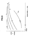
- FIG. 9 is a diagram showing the compression ratio control characteristics of the variable compression ratio control mechanism;
- FIG. 10 is a diagram of valve lift characteristics obtained by the control system of the present invention in relation to representative operating conditions of the engine;
- FIG. 11 illustrates intake valve operation characteristics in relation to an exhaust gas temperature and an influence of compression ratio on same;
- FIG. 12 is a time chart of operations of various portions of the engine after cold start; and
- Fig. 13 is a flow chart of a control routine of a compression ratio, etc. to be executed by the control system of FIG. 1.
-
- Referring to FIG. 1, an internal combustion engine includes variable valve
timing control apparatus 101 for varying intake valve opening and closing timings, compressionratio control mechanism 102 for varying nominal compression ratio E of the engine, ignitiontiming control system 103 for varying an ignition timing, and catalyticexhaust gas purifier 104 disposed in an exhaust system. - Variable valve
timing control apparatus 101 is shown in an enlarged scale in FIG. 2 and includes lift and operationangle control mechanism 1 for varying a lift and operation angle ofintake valve 12 and phase control mechanism for varying a phase ofintake valve 12, i.e., a maximum lift phase ofintake valve 12 relative to a rotational phase ofcrankshaft 51. - Firstly, with additional reference to FIGS. 3A and 3B, lift and operation
angle control mechanism 1 will be described. Lift and operationangle control mechanism 1 is structurally the same as that disclosed in Japanese Patent Provisional Publication No. 11-107725 which was assigned to the same assignee of this application, so that only brief description will be made thereto hereinafter. - Lift and operation
angle control mechanism 1 includeshollow drive shaft 13 rotatably supported oncylinder head 64 by cam brackets (not shown),eccentric cam 15 force-fitted or otherwise fixedly attached to driveshaft 13,control shaft 16 disposed above and in parallel withdrive shaft 13 and rotatably supported oncylinder head 64 by the above described cam brackets,rocker arm 18 mounted oneccentric cam portion 17 ofcontrol shaft 16 for oscillation motion, andoscillation cam 20 engagingtappet 19 provided to an upper end portion ofintake valve 12.Eccentric cam 15 androcker arm 18 are operatively connected bypivotal link 25, androcker arm 18 andoscillation cam 20 are operatively connected by connectingrod 26. -
Drive shaft 13 is driven bycrankshaft 51 of the engine by way of a timing chain or timing belt (not shown). -
Eccentric cam 15 has a circular external surface the center of which is offset from a rotational axis ofdrive shaft 13 by a predetermined amount. On the circular external surface is rotatably fitted or mountedannular base portion 25a ofpivotal link 25. -
Rocker arm 18 is mounted at a central portion thereof oneccentric cam portion 17 and has an end portion to which protrudedarm portion 25b of above describedpivotal link 25 is pivotally connected and another end portion to which an upper end portion of connectingrod 26 is pivotally connected. Eccentric cam portion17 has a geometric center that is offset from the rotational axis ofcontrol shaft 16 so that an axis of oscillation ofrocker arm 18 varies depending upon a variation of a rotational position or phase ofcontrol shaft 16. -
Oscillation cam 20 is rotatably mounted ondrive shaft 13 and has laterally protrudedend portion 20a to which a lower end portion of connectinglink 26 is pivotally connected.Oscillation cam 20 has at its lower side thereof basic circular ordwell surface 24a and cam orlift surface 24b extending from basiccircular surface 24a toward above describedend portion 20a so as to have a predetermined curved profile. Basiccircular surface 24a andcam surface 24b are brought into engagement with the upper surface oftappet 19 in response to oscillation ofoscillation cam 20. - Namely, basic
circular surface 24a serves as a base circle area that regulates an amount of lift to zero. Whenoscillation cam 20 is turned or rotated to bringcam surface 24b serving as a lift or rise area into contact withtappet 19, there is caused a lift ofintake valve 12 that increases gradually with further rotation ofoscillation cam 20. In the meantime, between the basic circular area and the lift area is provided a small ramp area. -
Control shaft 16 is constructed so as to be rotatable within a predetermined rotational angle range by being driven by hydraulic, lift and operationangle control actuator 31 installed on an end ofcontrol shaft 16 as shown in FIGS. 1 and 2. Supply of hydraulic pressure toactuator 31 is performed by firsthydraulic pressure controller 32 in response to a control signal from engine control unit (ECU) 33. - The operation of lift and operation
angle control mechanism 1 will now be described. Rotation ofdrive shaft 13 causespivotal link 25 to move up and down by the operation ofeccentric cam 15. By this,rocker arm 18 is caused to oscillate. This oscillating movement ofrocker arm 18 causesoscillation cam 20 to oscillate. By oscillating motion ofoscillation cam 20,tappet 19 is caused to move up and down, causingintake valve 19 to open and close. - In this connection, when the rotational position or phase of
control shaft 16 is varied byactuator 31, the initial position ofrocker arm 18 is caused to vary, and therefore the initial position ofoscillation cam 20 is caused to vary. - For example, when
eccentric cam portion 17 is generally positioned in a higher place as shown in FIG. 3A, i.e., when the geometric center ofeccentric cam portion 17 is located above the rotational axis ofcontrol shaft 16,rocker arm 18 is bodily moved into a higher place, thus causingend portion 20a ofoscillation cam 20 to be moved into a higher position. Namely, whenoscillation cam 20 is rotated into the initial position,cam surface 24b is caused to incline away fromtappet 19. Accordingly, whenoscillation cam 20 is caused to oscillate in response to rotation ofdrive shaft 13, basiccircular surface 24a is brought into contact withtappet 19 for a longer period, whereascam surface 24b is brought into contact withtappet 19 for a shorter period. Accordingly, the amount of lift is small, and an angular range from an opening timing to a closing timing, i.e., the operation angle is reduced. - On the contrary,
eccentric cam portion 17 is generally positioned in a lower place as shown in FIG. 3B,rocker arm 18 is bodily moved into a lower place, thus causingend portion 20a ofoscillation cam 20 to move into a lower position. Namely, whenoscillation cam 20 is rotated into the initial position,cam surface 24b is caused to incline towardtappet 19. Accordingly, whenoscillation cam 20 oscillates in response to rotation ofdrive shaft 13, the place whereoscillation cam 20 is brought into contact withtappet 19 changes immediately from basiccircular surface 24a tocam surface 24b. Accordingly, the amount of lift becomes larger and the operation angle is enlarged. - Since the position of
eccentric cam portion 17 can be varied continuously, the lift and operation angle characteristics ofintake valve 12 can be varied continuously as shown in FIG. 4. Namely, both of the lift and operation angle can be increased and decreased simultaneously and continuously. Particularly, by lift and operationangle control mechanism 1, the opening and closing timings are varied so as to be nearly symmetrical with respect to the maximum lift phase, in response to a variation of the lift and operation angle. - As shown in FIG. 2,
phase control mechanism 2 includessprocket 35 provided to a front end portion ofdrive shaft 13, and hydraulic,phase control actuator 36 for rotatingsprocket 35 relative to driveshaft 13 within a predetermined angular range.Sprocket 35 is drivingly connected to crankshaft 51 by way of the timing chain or timing belt (not shown) so as to be rotatable in timed relation tocrankshaft 51. Supply of oil pressure toactuator 36 is controlled by secondoil pressure controller 37 in response to a signal from engine control unit (ECU) 33. By the control of oil pressure to be supplied toactuator 36,sprocket 35 and driveshaft 13 are rotated relative to each other and the valve timing or phase is advanced or retarded as shown in FIG. 5. Namely, the curve representative of the valve lift characteristics does not change itself but is advanced or retarded in its entirety. Further, such a variation can be attained continuously.Phase control mechanism 2 is not limited to the hydraulic type but can have various other structures such as one utilizing an electromagnetic actuator. - Lift and operation
angle control mechanism 1 andphase control mechanism 2 can be open-loop controlled by using sensors (not shown) for detecting an actual lift, operation angle and maximum lift phase or can be simply closed-loop controlled in response to an engine operating condition. - FIG. 6 shows a compression
ratio control mechanism 102. - Compression
ratio control mechanism 102 includescrankshaft 51 having a plurality ofjournal portions 52 and a plurality of crank pins 53. On main bearings (not shown) installed oncylinder block 50 are rotatably supportedjournal portions 52. Crank pins 53 are offset fromjournal portions 52 by a predetermined amount. To each crankpin 53 is swingably or pivotally connectedlower link 54 serving as a second link. -
Lower link 54 is nearly T-shaped and made up of two separable sections. Nearly at a central portion oflower link 54 and between the separable sections is formed a connecting hole in which crankpin 53 is fitted. -
Upper link 55 serving as a first link is pivotally connected at a lower end to one end oflower link 54 by means of connectingpin 56 and at an upper end topiston 58 by means ofpiston pin 57.Piston 58 is subjected to a combustion pressure and reciprocates withincylinder 59 ofcylinder block 50. Abovecylinder 59 aredisposed intake valves 12 and exhaust valves (not shown). -
Control link 60 that serves as a third link is pivotally connected at an upper end to the other end oflower link 54 by means of connecting pin 61 and at a lower end to the engine main body such ascylinder block 50 by way ofcontrol shaft 62. More specifically,control shaft 62 is rotatably mounted on the engine main body and haseccentric cam portion 62a to which the lower end ofcontrol link 60 is pivotally connected. - Rotational position of
control shaft 62 is controlled by compressionratio control actuator 63 using an electric motor in response to a signal from engine control unit 33 (refer to FIG. 1). - In above described compression
ratio control mechanism 102 using a double-link type piston crank mechanism, whencontrol shaft 62 is turned by compressionratio control actuator 63, the center ofeccentric cam portion 62a is moved relative to the engine main body. This causes a variation of the position at which the lower end ofcontrol link 60 is pivotally supported on the engine main body. This in turn causes a variation in the stroke ofpiston 58, thus causing the position ofpiston 58 at the top dead center (TDC) to become higher or lower as shown in FIGS. 8A and 8B. By this, it becomes possible to change the compression ratio. FIGS. 8A and 8B show a high compression ratio condition and a low compression ratio condition, respectively. The compression ratio can be varied continuously between the high compression condition and low compression condition. - Above described double-link type compression
ratio control mechanism 102 can attain such piston crank stroke characteristics that approximates a single harmonic motion as shown in FIG. 7 by suitably selecting the link dimensions. The stroke characteristics approximating a single harmonic motion has an advantage in vibration noise, particularly in that the piston speed at or adjacent TDC is slower by about 20% as compared with an usual single-link type piston crank mechanism. This is an advantage in formation and development of initial flame kernel under the condition of slow combustion speed, e.g., at the time of cold engine. - The compression ratio control characteristics of above described compression
ratio control mechanism 102 are shown in FIG. 9. In the meantime, the compression ratio is a geometrical compression ratio ε that is determined depending upon only a volumetric variation of the combustion chamber that is caused by stroke ofpiston 58. In compressionratio control mechanism 102 that is combined with variable ignitiontiming control apparatus 101, the actual compression ratio is finally determined by the control of the intake valve closing timing. Namely, whenintake valve 12 is closed in the middle of the intake stroke, compression is actually started from a crank angle position that is symmetrical, with respect to BDC, to the crank angle position at whichintake valve 12 is closed. Thus, even if a nominal compression ratio ε is high, the actual compression ratio is lowered when the intake valve closing timing is earlier than BDC. - FIG. 10 shows the intake valve opening and closing timing control by variable valve
timing control apparatus 101 under typical vehicle driving conditions. In the meantime, corresponding points (or zones) to the driving conditions are added to FIG. 9. In this instance, 1 ○ to 4 ○ are the characteristics upon cold engine operation according to the present invention, and only 5 ○ is the characteristics after warming up of the engine (i.e., when the engine is hot), that are shown for reference. Further, the characteristics upon cold start are the same as the characteristics upon idling after warming up of the engine. As shown in FIG. 1, the temperature condition or worm-up condition of the engine is determined by one of or both ofcoolant temperature sensor 105 provided to, for example,cylinder block 50 of the engine andcatalyst temperature sensor 106 provided to catalyticexhaust gas purifier 104. - As shown, in the
characteristics 1 ○ upon cold engine operation, the operation angle is set to be small and the maximum lift phase is retarded so that the intake valve closing timing is set at a point a little earlier than BDC. Since the intake valve closing timing is set at a point adjacent BDC, decrease of the actual compression ratio is not caused. In thecharacteristics 2 ○ upon high idling of cold engine and thecharacteristics 3 ○ upon R/L (road load) running by cold engine, the operation angle is maintained small and the maximum lift phase is further retarded so that the intake valve opening timing is retarded as much as possible. Though the intake valve closing timing is after BDC, it is set at a point adjacent BDC and therefore decrease of the actual compression ratio is small. In the meantime, the ignition timing is retarded for warming up the catalyst of catalyticexhaust gas purifier 104. Upon high idling of cold engine, the degree of retardation of the ignition timing is maximized though varies depending upon the combustion condition. Namely, the ignition timing is retarded largely from an MBT (Minimum Spark Advance for Best Torque) point. In thecharacteristics 4 ○ upon acceleration by cold engine, for the necessity of making higher the intake air charging efficiency, the operation angle is enlarged and the intake valve opening timing is advanced. The intake valve closing timing is after TDC. In thecharacteristics 5 ○ upon R/L running after warming up, the intake valve opening timing is determined to be TDC for preventing production of vacuum and the intake valve closing timing is determined so as to advance considerably from BDC. By this, though the actual compression ratio is lowered, the nominal compression ratio ε is set to be high, thus making it possible to attain an effective pump loss reducing effect by the combination of the actual compression ratio and the nominal compression ratio. The R/L running is herein used to indicate running of the vehicle wherein the engine speed and engine load are constant and the throttle opening is 1/4 of full throttle. - FIG. 11 is a list for illustrating the effect of the intake valve operation characteristics and the compression ratio on the exhaust gas temperature when the engine is cold. In this instance, an exhaust gas temperature raising effect is shown by an arrow, i.e., the arrow directed upward indicates that the effect contributes to exhaust gas temperature rise and the arrow head directed downward indicates that the effect is bad for exhaust gas temperature rise. In the meantime, the exhaust gas temperature raising effect herein referred to is synonymous with how much the ignition timing can be retarded by the improvement of combustion. Hereinafter, description will be made to each item.
- (1) Retard (retard from TDC) of intake valve opening timing (IVO) When this is the case, intake air is not introduced into the cylinder at the initial stage of the intake stroke so that the vacuum within the cylinder increases rapidly. Further, the piston speed is maximized at the center of the stroke and simply increases as it moves from TDC to the center of the stroke. Thus, when the intake valve opening timing is retarded, the intake air flow speed becomes large when the intake valve is opened. Increase of the vacuum within the cylinder causes increase of the pumping loss, but increase of pumping loss causes a rise of the intake air temperature. Increase of the intake air flow speed is largely effective for promoting atomization of the fuel injected into the intake port. Further, since the combustion speed itself increases in accordance with the degree of turbulence of the intake air, the ignition timing can be retarded by the amount corresponding to increase of the combustion speed.
- (2) Making intake valve lift smaller When the intake valve lift is small, the intake air flow speed is increased by the amount corresponding to decrease of the opening area of the intake port. Particularly, there is a nozzle effect (effect of minimum restricted portion) between the intake valve and the seat. Such nozzle effect is largely effective for promoting atomization of the fuel injected into the intake port.
- (3) Retard (retard from BDC) of intake valve closing timing (IVC) By retarding the intake valve closing timing from BDC, the actual compression ratio is lowered. This is because the air-fuel mixture drawn into the cylinder is caused to flow backward at the initial stage of the compression stroke. As a matter of course, such retard is accompanied by decrease of the charging efficiency and therefore the intake vacuum is lowered. Decrease of the actual compression ratio causes the temperature of the air-fuel mixture at the time of compression to fall, thus lowering the combustion speed and imposing restrictions on retard of the ignition timing.Further, decrease of the intake vacuum deteriorates atomization of fuel and is therefore causative of lowering the combustion speed.
- (4) Advance (advance from BDC) of intake valve closing timing (IVC) When the intake valve closing timing is advanced to a point before BDC, the actual compression ratio is lowered similarly to the above-described retard of the intake valve closing timing. This is because, differing in phenomenon from retard of the intake valve closing timing, the mixture drawn into the cylinder is expanded adiabatically until BDC after closure of the intake valve and therefore the temperature of the mixture at BDC is lowered. As a matter of course, such advance is accompanied by lowering of the charging efficiency and therefore the intake vacuum is lowered. Accordingly, the combustion speed is lowered to put restrictions on retard of the ignition timing.
- (5) In case of making intake valve closing timing closer
to BDC
In this case, reversely to the above-described
characteristics 3 ○ and 4 ○, the actual compression ratio is elevated and the intake vacuum is intensified, thus causing the combustion temperature to rise and the retard limit of the ignition timing is enlarged. - (6) In case of making compression ratio ε higher When the compression ratio ε is made higher, the temperature at or adjacent TDC is caused to rise. Thus, good combustion can be attained even if the ignition timing is retarded. Further, though the expansion ratio is increased, the retard limit is enlarged by the corresponding amount, particularly when a curve representative of the piston stroke characteristics is close to a single harmonic vibration, thus making it possible to obtain an effect capable of offsetting increase of the expansion ratio sufficiently.
- (7) In case of making the compression ratio ε smaller When the compression ratio ε is made smaller; the temperature of the mixture when the piston is at or adjacent TDC is lowered, thus causing the combustion speed to be lower and the ignition timing to be restricted. This is well over the influence of decrease of expansion ratio.
- (8) In case of making the compression ratio higher and not retarding the ignition timing (for reference) Combustion becomes better and the compression ratio is increased, thus allowing the efficiency to become better. Accordingly, the temperature of the exhaust gas is lowered.
-
- Fig. 12 is a time chart for illustrating a control performed at the transition from the high idling condition after cold start to the R/L running through the slow acceleration. When the engine in a cold condition is started and put into self-sustaining operation, the rpm is set higher than that at idling after warming up, i.e., the engine is put into a so-called high idling condition. From this time onward, it is necessary to make a control for maximizing the exhaust gas temperature for exhaust gas purification.
- In this example, upon high idling, the compression ratio ε is set high, and at the same time the characteristics of the intake valve is varied in such a manner that the operation angle is made smaller (this is for enlarging the freedom of retardation) and the intake valve opening timing (IVO) is retarded largely in combination with retard of the maximum lift phase . In this instance, the intake valve closing timing (IVC) is set at a point after BDC. This is for retarding the intake valve opening timing (IVO) maximumly. However, the intake valve opening timing (IVO) is set at a point adjacent BDC, though after BDC, so that the influence on the actual compression ratio is small. Upon this high idling, the degree of retard of the ignition timing is maximized though varies depending upon the combustion condition.
- When the vehicle operating condition is changed from high idling to acceleration, the compression ratio E is a little lowered from the maximum value but still set to be high. Since the coolant temperature rises gradually, the compression ratio ε is lowered gradually in accordance with a rise of the coolant temperature. Catalytic
exhaust gas purifier 104 soon reaches the conversion starting temperature. From this time onward, retard of the ignition timing is cancelled gradually and the control is varied so that the intake valve opening timing (IVO) and the intake valve closing timing (IVC) are regulated to the target values. - FIG. 13 is a flow chart of a control routine to be executed by the control system of this invention when the engine is cold or hot. Firstly, in step S1, it is judged whether the coolant temperature and the catalyst temperature are equal to or higher than respective predetermined temperatures and then it is judged, based on the judgment on the coolant temperature and the catalyst temperature, whether the engine is cold or hot. When the engine is judged cold, the program proceeds to step S2. In step S2, selection of maps for respective control of the compression ratio ε, ignition timing IT, intake valve opening timing (IVO) and intake valve closing timing (IVC) is made. In step S3, an actual engine operating condition (engine rpm, throttle opening degree) at that time is detected and a control corresponding to the detected engine operating condition is made on the basis of the selected maps. Namely, in steps S4 and S5, variable compression
ratio control mechanism 102 is controlled so that the compression ratio ε becomes equal to a target value. In steps S6 and S7, lift and operationangle control mechanism 1 andphase control mechanism 2 are controlled so that the intake valve opening timing (IVO) and the intake valve closing timing (IVC) become equal to respective target values. Further, in steps S8 and S9, ignitiontiming control system 103 is controlled so that the ignition timing IT becomes equal to a target value. - When the engine is judged hot in step S1, the control proceeds to step S12 to select control maps for hot engine. From this step onward, a control similar to that described above is carried out. Namely, steps S12 to S19 correspond to steps S2 to S9, respectively, so that a repeated description thereto is omitted.
- In the foregoing, it is to be noted that the above described control of variable
valve timing apparatus 101 and compressionratio control mechanism 102 are executed by a control program incorporated inECU 33. - From the foregoing, it will be understood that according to the present invention, the exhaust gas temperature can be raised efficiently without deteriorating the combustion. Namely, by raising the compression ratio (i.e., nominal compression ratio ε), the temperature of the mixture when the piston is adjacent TDC becomes higher. By this, it becomes possible to obtain good combustion even if the ignition timing is retarded largely. In this connection, while the expansion ratio increases as the compression ratio becomes higher, the exhaust gas temperature becomes higher since the limit of retardation of the ignition timing is enlarged.
- It will be further understood that according to the present invention, the lift and operation angle are set to be small when the engine is cold. By this, it becomes possible to retard the ignition timing largely and attain an efficient rise of the exhaust gas temperature.
- It will be further understood that according to the present invention, the compression ratio control mechanism is constructed so that reciprocating motion of the piston of the engine in response to rotation of the crankshaft approximates to a single harmonic motion. This is effective for obtaining stable combustion even when the engine is cold.
- The entire contents of Japanese Patent Application No. 2001-89326 are incorporated herein by reference.
- Although the invention has been described above by reference to a certain embodiment of the invention, the invention is not limited to the embodiment described above. Modifications and variations of the embodiment described above will occur to those skilled in the art, in light of the above teachings. The scope of the invention is defined with reference to the following claims.
Claims (29)
- A control system for an internal combustion engine having a compression ratio control mechanism (102) capable of varying a compression ratio of the engine, an ignition timing control system (103) capable of varying an ignition timing of the engine, and a catalytic exhaust gas purifier (104) disposed in an exhaust system of the engine, the control system comprising:an engine control unit (33) for controlling the compression ratio control mechanism (102) and the ignition timing control system (103) so that the compression ratio (ε) is varied depending upon variations of engine rpm, engine load and a warm-up condition of the engine and that when the engine is cold, the ignition timing is retarded largely from an MBT point and the compression ratio (ε) is set higher than that obtained when the engine is hot and operated at corresponding engine rpm and engine load.
- A control system according to claim 1, wherein the engine further includes a lift and operation angle control mechanism (1) capable of varying a lift and operation angle of an intake valve (12) of the engine simultaneously and continuously, and wherein the engine control unit (33) controls the lift and operation angle control mechanism (1) so that the lift and operation angle are varied continuously depending upon variations of the engine rpm and the engine load and that when the engine is cold, the lift and operation angle are set to be small.
- A control system according to claim 2, wherein the engine further includes a phase control mechanism (2) capable of varying a maximum lift phase () of the intake valve (12), and wherein the engine control unit (33) controls the phase control mechanism (2) so that when the engine is cold, the maximum lift phase () of the intake valve (12) is retarded so as to retard an intake valve opening timing (IVO) to a point after an intake top dead center.
- A control system according to claim 3, wherein the engine control unit (33) controls the phase control mechanism (2) so that retard of the maximum lift phase () is set to be large when the lift and the operation angle are small.
- A control system according to claim 3 or 4, wherein the engine control unit (33) controls the phase control mechanism (2) so that when the engine is cold, an intake valve closing timing (IVC) is set at a point closer to an intake bottom dead center than a point at which the intake valve closing timing is set after the engine is warmed up.
- A control system according to any one of claims 3 to 5, wherein the engine control unit (33) controls the phase control mechanism (2) so that at idling after the engine is warmed up, an intake valve closing timing (IVC) is set at a point adjacent the intake bottom dead center.
- A control system according to claim any one of claims 1 to 6, wherein the engine control unit (33) controls the ignition timing control system (103) so that when the engine is cold, the ignition timing is retarded to a point adjacent or after a compression top dead center.
- A control system according to any one of claims 1 to 7, wherein the engine control unit (33) controls so that the engine rpm at cold idling is controlled higher than that at idling after the engine is warmed up.
- A control system according to any one of claims 1 to 8, wherein the engine control unit (33) controls the ignition timing control system (103) so that retard of the ignition timing is decreased gradually with increase of the engine load.
- A control system according to any one of claims 1 to 9, wherein the compression ratio control mechanism (102) is constructed so that reciprocating motion of a piston (5) of the engine in response to rotation of a crankshaft (51) approximates to a single harmonic motion.
- An internal combustion engine comprising:a compression ratio control mechanism (102) capable of varying a compression ratio of the engine;an ignition timing control system (103) capable of varying an ignition timing of the engine; andan engine control unit (33) for controlling the compression ratio control mechanism (102) and the ignition timing control system (103) so that the compression ratio (ε) is varied depending upon variations of engine rpm, engine load and a warm-up condition of the engine and that when the engine is cold, the ignition timing is retarded largely from an MBT point and the compression ratio is set higher than that obtained when the engine is hot and operated at corresponding engine rpm and engine load.
- An internal combustion engine according to claim 13, wherein the compression ratio control mechanism (102) is constructed so that reciprocating motion of a piston (58) of the engine in response to rotation of a crankshaft (51) approximates a single harmonic motion.
- An internal combustion engine according to claim 12, wherein the compression ratio control mechanism (102) includes a first link (55) connected at one of opposite ends to a piston pin (57) of a piston (58) of the engine, a second link (54) connecting between the other of the opposite ends of the first link (55) and a crank pin (53) of a crankshaft (51) of the engine, and a third link (60) connected at one of opposite ends to the second link (54) and at the other of the opposite ends to a main body of the engine.
- An internal combustion engine according to claim 13, wherein the engine control unit (33) controls the compression ratio control mechanism (102) so that a support point (62a) of the third link (60) with respect to the main body of the engine varies depending upon a variation of an operating condition of the engine thereby varying the compression ratio (ε).
- An internal combustion engine according to claim 11, further comprising a lift and operation angle control mechanism (1) capable of varying a lift and operation angle of an intake valve (12) of the engine simultaneously and continuously, wherein the engine control unit (33) controls the lift and operation angle control mechanism (1) so that the lift and operation angle are varied continuously depending upon variations of engine rpm and engine load and that when the engine is cold, the lift and operation angle are set to be small.
- An internal combustion engine according to claim 15, further comprising a phase control mechanism (2) capable of varying a maximum lift phase of the intake valve (12), wherein the engine control unit (33) controls the phase control mechanism (2) so that when the engine is cold, the maximum lift phase () of the intake valve (12) is retarded so as to retard an intake valve opening timing (IVO) to a point after an intake top dead center.
- An internal combustion engine according to claim 16, wherein the engine control unit (33) controls the phase control mechanism (2) so that retard of the maximum lift phase () is set to be large when the lift and the operation angle are small.
- An internal combustion engine according to claim 16 or 17, wherein the engine control unit (33) controls the phase control mechanism (2) so that when the engine is cold, an intake valve closing timing (IVC) is set at a point closer to an intake bottom dead center than a point at which the intake valve closing timing (IVC) is set after the engine is warmed up.
- An internal combustion engine according to any one of claims 16 to 18, wherein the engine control unit (33) controls the phase control mechanism (2) so that at idling after the engine is warmed up, the intake valve closing timing (IVC) is set at a point adjacent the intake bottom dead center.
- A control system according to any one of claims 11 to 19, wherein the engine control unit (33) controls the ignition timing control system (103) so that when the engine is cold, the ignition timing is retarded to a point adjacent or after a compression top dead center.
- An internal combustion engine according to any one of claims 11 to 20, wherein the engine control unit (33) controls the ignition timing control system (103) so that retard of the ignition timing is decreased gradually with increase of the engine load.
- A method for controlling an internal combustion engine having a compression ratio control mechanism (102) capable of varying a compression ratio (ε) of the engine, an ignition timing control system (103) capable of varying an ignition timing of the engine, and a catalytic exhaust gas purifier (103) disposed in an exhaust system of the engine, the method comprising:controlling the compression ratio control mechanism (102) and the ignition timing control system (103) so that the compression ratio (ε) is varied depending upon variations of engine rpm, engine load and a warm-up condition of the engine and that when the engine is cold, the ignition timing is retarded largely from an MBT point and the compression ratio (ε) is set higher than that obtained when the engine is hot and operated at corresponding engine rpm and engine load.
- A method according to claim 22, wherein the engine further includes a lift and operation angle control mechanism (1) capable of varying a lift and operation angle of an intake valve (12) of the engine simultaneously and continuously, and wherein the method further comprises controlling the lift and operation angle control mechanism (1) so that the lift and the operation angle are varied continuously depending upon variations of the engine rpm and the engine load and that when the engine is cold, the lift and the operation angle are set to be small.
- A method according to claim 23, wherein the engine further includes a phase control mechanism (2) capable of varying a maximum lift phase of an intake valve (12) of the engine, and wherein the method further comprises controlling the phase control mechanism (2) so that the maximum lift phase of the intake valve (12) is retarded so as to retard an intake valve opening timing (IVO) to a point after an intake top dead center.
- A method according to claim 24, wherein the method further comprises controlling the phase control mechanism (2) so that retard of the maximum lift phase is set to be large when the lift and the operation angle are small.
- A method according to claim 24 or 25, further comprising controlling the phase control mechanism (2) so that when the engine is cold, an intake valve closing timing (IVC) is set at a point closer to an intake bottom dead center than a point at which the intake valve closing timing (IVC) is set after the engine is warmed up.
- A method according to any one of claims 24 to 26, further comprising controlling the phase control mechanism (2) so that at idling after the engine is warmed up, the intake valve closing timing (IVC) is set at a point adjacent the intake bottom dead center.
- A method according to any one of claims 22 to 26, further comprising controlling the ignition timing control system (103) so that when the engine is cold, the ignition timing is retarded to a point adjacent or after a compression top dead center.
- A method according to any one of claims 22 to 28, further comprising controlling the ignition timing control system (103) so that retard of the ignition timing is decreased gradually with increase of the engine load.
Applications Claiming Priority (2)
| Application Number | Priority Date | Filing Date | Title |
|---|---|---|---|
| JP2001089326 | 2001-03-27 | ||
| JP2001089326A JP4035963B2 (en) | 2001-03-27 | 2001-03-27 | Control device for internal combustion engine |
Publications (3)
| Publication Number | Publication Date |
|---|---|
| EP1247971A2 true EP1247971A2 (en) | 2002-10-09 |
| EP1247971A3 EP1247971A3 (en) | 2004-08-11 |
| EP1247971B1 EP1247971B1 (en) | 2008-12-17 |
Family
ID=18944267
Family Applications (1)
| Application Number | Title | Priority Date | Filing Date |
|---|---|---|---|
| EP02005521A Expired - Lifetime EP1247971B1 (en) | 2001-03-27 | 2002-03-11 | Control device and method for an internal combustion engine |
Country Status (4)
| Country | Link |
|---|---|
| US (1) | US6732682B2 (en) |
| EP (1) | EP1247971B1 (en) |
| JP (1) | JP4035963B2 (en) |
| DE (1) | DE60230355D1 (en) |
Cited By (5)
| Publication number | Priority date | Publication date | Assignee | Title |
|---|---|---|---|---|
| EP1602816A1 (en) * | 2004-06-04 | 2005-12-07 | Ford Global Technologies, LLC | Method and apparatus for reducing exhaust gas emissions during cold start conditions |
| RU2312998C2 (en) * | 2002-11-04 | 2007-12-20 | Карджайн Энджиниринг АБ | Engine with variable compression ratio and frequency modulation |
| EP1980734A3 (en) * | 2007-04-13 | 2010-12-22 | Mazda Motor Corporation | Internal combustion engine having variable valve lift mechanism |
| RU2443886C2 (en) * | 2007-11-07 | 2012-02-27 | Тойота Дзидося Кабусики Кайся | Control device |
| US8818693B2 (en) | 2008-12-03 | 2014-08-26 | Toyota Jidosha Kabushiki Kaisha | Engine system control device |
Families Citing this family (23)
| Publication number | Priority date | Publication date | Assignee | Title |
|---|---|---|---|---|
| JP2004308510A (en) | 2003-04-04 | 2004-11-04 | Toyota Motor Corp | Internal combustion engine that controls by detecting failure of the compression ratio changing mechanism |
| US6938593B2 (en) * | 2003-11-13 | 2005-09-06 | Ford Global Technologies, Llc | Computer readable storage medium for use with engine having variable valve actuator |
| US7257683B2 (en) * | 2004-03-24 | 2007-08-14 | Micron Technology, Inc. | Memory arbitration system and method having an arbitration packet protocol |
| JP4497089B2 (en) * | 2005-12-13 | 2010-07-07 | トヨタ自動車株式会社 | Control device for internal combustion engine |
| JP4702103B2 (en) * | 2006-03-01 | 2011-06-15 | 日産自動車株式会社 | Engine intake control method and intake control device |
| JP2007303423A (en) * | 2006-05-12 | 2007-11-22 | Toyota Motor Corp | Spark ignition internal combustion engine |
| JP4749988B2 (en) * | 2006-10-23 | 2011-08-17 | 日立オートモティブシステムズ株式会社 | Start control device for internal combustion engine |
| KR100771821B1 (en) | 2006-10-31 | 2007-10-30 | 지멘스 오토모티브 주식회사 | Control Method of Variable Valve Timing Device for Catalytic Heating |
| JP4830998B2 (en) * | 2007-07-17 | 2011-12-07 | 株式会社デンソー | Valve characteristic control device and valve characteristic control system |
| JP4483915B2 (en) | 2007-09-06 | 2010-06-16 | トヨタ自動車株式会社 | Idling control device for spark ignition type internal combustion engine |
| JP4367548B2 (en) * | 2007-11-06 | 2009-11-18 | トヨタ自動車株式会社 | Spark ignition internal combustion engine |
| JP4367549B2 (en) * | 2007-11-06 | 2009-11-18 | トヨタ自動車株式会社 | Spark ignition internal combustion engine |
| JP4428442B2 (en) * | 2007-11-08 | 2010-03-10 | トヨタ自動車株式会社 | Spark ignition internal combustion engine |
| JP4998336B2 (en) * | 2008-03-11 | 2012-08-15 | 日産自動車株式会社 | Control device and control method for variable compression ratio engine |
| JP2010168939A (en) * | 2009-01-21 | 2010-08-05 | Toyota Motor Corp | High expansion ratio internal combustion engine |
| JP2010241170A (en) * | 2009-04-01 | 2010-10-28 | Toyota Motor Corp | Power output apparatus, hybrid vehicle provided with the same, and method of controlling power output apparatus |
| JP5177303B2 (en) * | 2009-12-28 | 2013-04-03 | トヨタ自動車株式会社 | Spark ignition internal combustion engine |
| WO2011092867A1 (en) * | 2010-01-28 | 2011-08-04 | トヨタ自動車株式会社 | Spark-ignition internal combustion engine |
| JP5472076B2 (en) * | 2010-12-20 | 2014-04-16 | トヨタ自動車株式会社 | Spark ignition internal combustion engine |
| DE102015002722A1 (en) | 2015-03-04 | 2016-09-08 | Daimler Ag | Method for operating an adjusting device for setting a compression ratio, as well as adjusting device |
| JP6494502B2 (en) * | 2015-12-24 | 2019-04-03 | 日立オートモティブシステムズ株式会社 | Piston stroke adjusting device for internal combustion engine |
| JP6311739B2 (en) | 2016-03-31 | 2018-04-18 | マツダ株式会社 | Engine control device |
| US10273927B2 (en) * | 2017-03-01 | 2019-04-30 | Ford Global Technologies, Llc | Controlling variable compression ratio with a pressure-reactive piston |
Citations (2)
| Publication number | Priority date | Publication date | Assignee | Title |
|---|---|---|---|---|
| JPH11107725A (en) | 1997-08-07 | 1999-04-20 | Unisia Jecs Corp | Variable valve train for internal combustion engine |
| JP2000073804A (en) | 1998-09-01 | 2000-03-07 | Toyota Autom Loom Works Ltd | Internal combustion engine and control device therefor |
Family Cites Families (8)
| Publication number | Priority date | Publication date | Assignee | Title |
|---|---|---|---|---|
| JP2518878B2 (en) * | 1987-12-18 | 1996-07-31 | 日産自動車株式会社 | Ignition timing control device for variable compression ratio internal combustion engine |
| DE3807244C1 (en) * | 1988-03-05 | 1989-03-23 | Daimler-Benz Aktiengesellschaft, 7000 Stuttgart, De | |
| JPH0626431A (en) * | 1992-05-07 | 1994-02-01 | Nissan Motor Co Ltd | Ignition timing control device of internal combustion engine |
| JP3812154B2 (en) * | 1997-08-06 | 2006-08-23 | マツダ株式会社 | Engine control device |
| JPH11324625A (en) | 1998-05-19 | 1999-11-26 | Nissan Motor Co Ltd | Variable valve mechanism of internal combustion engine |
| DE29913107U1 (en) * | 1999-07-27 | 1999-10-07 | Fend, Fritz, 93138 Lappersdorf | Internal combustion engine |
| DE10002771A1 (en) * | 1999-09-10 | 2001-03-15 | Porsche Ag | Valve control in internal combustion engines |
| US6394051B1 (en) * | 2000-09-01 | 2002-05-28 | Ford Global Technologies, Inc. | Spark ignition engine with negative valve-overlap |
-
2001
- 2001-03-27 JP JP2001089326A patent/JP4035963B2/en not_active Expired - Lifetime
-
2002
- 2002-02-22 US US10/079,588 patent/US6732682B2/en not_active Expired - Lifetime
- 2002-03-11 DE DE60230355T patent/DE60230355D1/en not_active Expired - Lifetime
- 2002-03-11 EP EP02005521A patent/EP1247971B1/en not_active Expired - Lifetime
Patent Citations (2)
| Publication number | Priority date | Publication date | Assignee | Title |
|---|---|---|---|---|
| JPH11107725A (en) | 1997-08-07 | 1999-04-20 | Unisia Jecs Corp | Variable valve train for internal combustion engine |
| JP2000073804A (en) | 1998-09-01 | 2000-03-07 | Toyota Autom Loom Works Ltd | Internal combustion engine and control device therefor |
Cited By (8)
| Publication number | Priority date | Publication date | Assignee | Title |
|---|---|---|---|---|
| RU2312998C2 (en) * | 2002-11-04 | 2007-12-20 | Карджайн Энджиниринг АБ | Engine with variable compression ratio and frequency modulation |
| EP1602816A1 (en) * | 2004-06-04 | 2005-12-07 | Ford Global Technologies, LLC | Method and apparatus for reducing exhaust gas emissions during cold start conditions |
| US7124734B2 (en) | 2004-06-04 | 2006-10-24 | Ford Global Technologies, Llc | Method of reducing exhaust gas emissions during cold start conditions and an internal combustion engine in which the method is used |
| EP1980734A3 (en) * | 2007-04-13 | 2010-12-22 | Mazda Motor Corporation | Internal combustion engine having variable valve lift mechanism |
| CN101285410B (en) * | 2007-04-13 | 2012-06-06 | 马自达汽车株式会社 | Engine system and control method of the engine |
| RU2443886C2 (en) * | 2007-11-07 | 2012-02-27 | Тойота Дзидося Кабусики Кайся | Control device |
| US8656701B2 (en) | 2007-11-07 | 2014-02-25 | Toyota Jidosha Kabushiki Kaisha | Control device |
| US8818693B2 (en) | 2008-12-03 | 2014-08-26 | Toyota Jidosha Kabushiki Kaisha | Engine system control device |
Also Published As
| Publication number | Publication date |
|---|---|
| EP1247971B1 (en) | 2008-12-17 |
| DE60230355D1 (en) | 2009-01-29 |
| JP4035963B2 (en) | 2008-01-23 |
| US6732682B2 (en) | 2004-05-11 |
| US20020139346A1 (en) | 2002-10-03 |
| EP1247971A3 (en) | 2004-08-11 |
| JP2002285898A (en) | 2002-10-03 |
Similar Documents
| Publication | Publication Date | Title |
|---|---|---|
| US6732682B2 (en) | Control system and method for an internal combustion engine | |
| EP1363002B1 (en) | Control system and method for an internal combustion engine with variable compression ratio | |
| EP1223319B1 (en) | Combustion control system for spark ignition internal combustion engine with variable piston stroke characteristic mechanism and variable valve operating mechanism | |
| US6792924B2 (en) | Engine control system of internal combustion engine with variable compression ratio mechanism and exhaust-gas recirculation control system | |
| US6705257B2 (en) | Apparatus and method for controlling variable valve in internal combustion engine | |
| JP4581273B2 (en) | Start-up control device for internal combustion engine | |
| US7267104B2 (en) | Internal combustion engine start-up control | |
| JP2003065089A (en) | Variable valve train for internal combustion engines | |
| JP4402798B2 (en) | Control device for internal combustion engine | |
| JP2002089341A (en) | Control device for internal combustion engine for vehicles | |
| JP4135394B2 (en) | Control device for internal combustion engine | |
| JP3829629B2 (en) | Combustion control device for internal combustion engine | |
| JP2007239555A (en) | Internal combustion engine | |
| JP2002089302A (en) | Valve control device for internal combustion engine | |
| JP4590746B2 (en) | Variable valve operating device for internal combustion engine | |
| JP2007239550A (en) | Variable compression ratio engine | |
| JP4604358B2 (en) | Internal combustion engine and control system thereof | |
| JP2008111397A (en) | Cycle variable stroke engine | |
| JP2009203896A (en) | Internal combustion engine and method for controlling internal combustion engine | |
| JPH11247637A (en) | Variable valve train for internal combustion engine | |
| JP2003328790A (en) | Engine valve control unit | |
| JPH08260919A (en) | Engine valve timing controller |
Legal Events
| Date | Code | Title | Description |
|---|---|---|---|
| PUAI | Public reference made under article 153(3) epc to a published international application that has entered the european phase |
Free format text: ORIGINAL CODE: 0009012 |
|
| 17P | Request for examination filed |
Effective date: 20020311 |
|
| AK | Designated contracting states |
Kind code of ref document: A2 Designated state(s): AT BE CH CY DE DK ES FI FR GB GR IE IT LI LU MC NL PT SE TR |
|
| AX | Request for extension of the european patent |
Free format text: AL;LT;LV;MK;RO;SI |
|
| PUAL | Search report despatched |
Free format text: ORIGINAL CODE: 0009013 |
|
| AK | Designated contracting states |
Kind code of ref document: A3 Designated state(s): AT BE CH CY DE DK ES FI FR GB GR IE IT LI LU MC NL PT SE TR |
|
| AX | Request for extension of the european patent |
Extension state: AL LT LV MK RO SI |
|
| RIC1 | Information provided on ipc code assigned before grant |
Ipc: 7F 02D 41/06 B Ipc: 7F 02D 37/02 A Ipc: 7F 02D 15/00 B Ipc: 7F 02D 41/02 B |
|
| 17Q | First examination report despatched |
Effective date: 20050310 |
|
| AKX | Designation fees paid |
Designated state(s): DE FR GB |
|
| RBV | Designated contracting states (corrected) |
Designated state(s): DE FR GB |
|
| GRAP | Despatch of communication of intention to grant a patent |
Free format text: ORIGINAL CODE: EPIDOSNIGR1 |
|
| RTI1 | Title (correction) |
Free format text: CONTROL DEVICE AND METHOD FOR AN INTERNAL COMBUSTION ENGINE |
|
| GRAS | Grant fee paid |
Free format text: ORIGINAL CODE: EPIDOSNIGR3 |
|
| GRAA | (expected) grant |
Free format text: ORIGINAL CODE: 0009210 |
|
| AK | Designated contracting states |
Kind code of ref document: B1 Designated state(s): DE FR GB |
|
| REG | Reference to a national code |
Ref country code: GB Ref legal event code: FG4D |
|
| REF | Corresponds to: |
Ref document number: 60230355 Country of ref document: DE Date of ref document: 20090129 Kind code of ref document: P |
|
| PLBE | No opposition filed within time limit |
Free format text: ORIGINAL CODE: 0009261 |
|
| STAA | Information on the status of an ep patent application or granted ep patent |
Free format text: STATUS: NO OPPOSITION FILED WITHIN TIME LIMIT |
|
| 26N | No opposition filed |
Effective date: 20090918 |
|
| REG | Reference to a national code |
Ref country code: FR Ref legal event code: PLFP Year of fee payment: 15 |
|
| REG | Reference to a national code |
Ref country code: FR Ref legal event code: PLFP Year of fee payment: 16 |
|
| REG | Reference to a national code |
Ref country code: FR Ref legal event code: PLFP Year of fee payment: 17 |
|
| PGFP | Annual fee paid to national office [announced via postgrant information from national office to epo] |
Ref country code: FR Payment date: 20210210 Year of fee payment: 20 |
|
| PGFP | Annual fee paid to national office [announced via postgrant information from national office to epo] |
Ref country code: DE Payment date: 20210224 Year of fee payment: 20 Ref country code: GB Payment date: 20210308 Year of fee payment: 20 |
|
| REG | Reference to a national code |
Ref country code: DE Ref legal event code: R071 Ref document number: 60230355 Country of ref document: DE |
|
| REG | Reference to a national code |
Ref country code: GB Ref legal event code: PE20 Expiry date: 20220310 |
|
| PG25 | Lapsed in a contracting state [announced via postgrant information from national office to epo] |
Ref country code: GB Free format text: LAPSE BECAUSE OF EXPIRATION OF PROTECTION Effective date: 20220310 |