EP1247703A1 - Seat belt system for vehicles and vehicle provided therewith - Google Patents
Seat belt system for vehicles and vehicle provided therewith Download PDFInfo
- Publication number
- EP1247703A1 EP1247703A1 EP20020006642 EP02006642A EP1247703A1 EP 1247703 A1 EP1247703 A1 EP 1247703A1 EP 20020006642 EP20020006642 EP 20020006642 EP 02006642 A EP02006642 A EP 02006642A EP 1247703 A1 EP1247703 A1 EP 1247703A1
- Authority
- EP
- European Patent Office
- Prior art keywords
- door
- vehicle
- opening
- seat
- guide member
- Prior art date
- Legal status (The legal status is an assumption and is not a legal conclusion. Google has not performed a legal analysis and makes no representation as to the accuracy of the status listed.)
- Granted
Links
- 230000000452 restraining effect Effects 0.000 claims abstract description 8
- 238000009751 slip forming Methods 0.000 claims description 4
- 238000010276 construction Methods 0.000 description 2
- 229910000831 Steel Inorganic materials 0.000 description 1
- 239000004809 Teflon Substances 0.000 description 1
- 229920006362 Teflon® Polymers 0.000 description 1
- 230000009286 beneficial effect Effects 0.000 description 1
- 239000011248 coating agent Substances 0.000 description 1
- 238000000576 coating method Methods 0.000 description 1
- 230000001419 dependent effect Effects 0.000 description 1
- 239000000463 material Substances 0.000 description 1
- 230000002093 peripheral effect Effects 0.000 description 1
- 239000011347 resin Substances 0.000 description 1
- 229920005989 resin Polymers 0.000 description 1
- 239000010959 steel Substances 0.000 description 1
- 210000005182 tip of the tongue Anatomy 0.000 description 1
Images



Classifications
-
- B—PERFORMING OPERATIONS; TRANSPORTING
- B60—VEHICLES IN GENERAL
- B60J—WINDOWS, WINDSCREENS, NON-FIXED ROOFS, DOORS, OR SIMILAR DEVICES FOR VEHICLES; REMOVABLE EXTERNAL PROTECTIVE COVERINGS SPECIALLY ADAPTED FOR VEHICLES
- B60J5/00—Doors
- B60J5/04—Doors arranged at the vehicle sides
- B60J5/047—Doors arranged at the vehicle sides characterised by the opening or closing movement
- B60J5/0477—Doors arranged at the vehicle sides characterised by the opening or closing movement with two doors opening in opposite direction
- B60J5/0479—Doors arranged at the vehicle sides characterised by the opening or closing movement with two doors opening in opposite direction without B-pillar or releasable B-pillar, i.e. the pillar is moving with door
-
- B—PERFORMING OPERATIONS; TRANSPORTING
- B60—VEHICLES IN GENERAL
- B60R—VEHICLES, VEHICLE FITTINGS, OR VEHICLE PARTS, NOT OTHERWISE PROVIDED FOR
- B60R22/00—Safety belts or body harnesses in vehicles
- B60R22/02—Semi-passive restraint systems, e.g. systems applied or removed automatically but not both ; Manual restraint systems
- B60R22/022—Semi-passive restraint systems, e.g. systems applied or removed automatically but not both ; Manual restraint systems with means for facilitating access to rear seats in two-door cars
-
- B—PERFORMING OPERATIONS; TRANSPORTING
- B60—VEHICLES IN GENERAL
- B60R—VEHICLES, VEHICLE FITTINGS, OR VEHICLE PARTS, NOT OTHERWISE PROVIDED FOR
- B60R22/00—Safety belts or body harnesses in vehicles
- B60R22/18—Anchoring devices
- B60R22/22—Anchoring devices secured to the vehicle floor
-
- B—PERFORMING OPERATIONS; TRANSPORTING
- B60—VEHICLES IN GENERAL
- B60R—VEHICLES, VEHICLE FITTINGS, OR VEHICLE PARTS, NOT OTHERWISE PROVIDED FOR
- B60R22/00—Safety belts or body harnesses in vehicles
- B60R22/18—Anchoring devices
- B60R22/24—Anchoring devices secured to the side, door, or roof of the vehicle
Definitions
- the present invention relates to a seat belt system for a vehicle, more particularly, a seat belt system for a vehicle equipped with a double door structure, and to a vehicle provided with such seat belt system.
- a double door structure is well known as disclosed in Japanese patent publication No. H8-142680.
- the conventional structure includes a lock pillar extending vertically in the middle portion of a rear opening which is opened and closed by a left-side door and a right-side door in a double door configuration.
- Such a double door structure may be adopted to an ingress and egress opening on the side of a vehicle.
- a center-pillar would extend vertically in the middle portion of the ingress and egress opening, which is beneficial to the rigidity of the vehicle body, but is disadvantageous to the openness.
- a center-pillar-less structure, without the center-pillar is preferable.
- Japanese patent publication No. S63-130450 discloses a seat belt system, which is so configured that a belt webbing of the seat belt system for the front-seat passenger is extended from the inside of the rear door to a front seat.
- the front door and the rear door combined with the seat belt system disclosed in the patent publication above are not of a double door structure, but the rear door is swingable about its frontal portion and the belt webbing locates in the vicinity of the pivotal axis of the rear door, causing no difficulties for the rear door to open.
- the seat belt system is disadvantageously adopted to the double door structure.
- the object of the present invention is to provide a seat belt system for a vehicle and a vehicle provided therewith which achieve enhanced convenience of ingress and egress for the passengers.
- a seat belt system for a vehicle, for restraining an occupant in a seat disposed in a passenger compartment of the vehicle, the vehicle including an opening formed on at least one side of a vehicular body, wherein the seat belt system comprises, a belt webbing or seat belt or safety belt system, a retractor or belt retractor to be disposed at or on or in a first door of the vehicle for retracting a first end of said belt webbing, a sliding or gliding means to be fixed on a lower edge of the opening, to which a second end of said belt webbing is attached so that the second end of said belt webbing is allowed to slide or glide or relatively move along a lower edge of the opening at least between a first position and a second position.
- an enhanced convenience of ingress and egress for the passengers is achieved, in particular with the improved appearance of the belt webbing of the seat belt system while the door being open, especially, which attains the openness of the door opening and improved accessibility for the legs of the passenger.
- a seat belt system for a vehicle, for restraining the passenger in a seat disposed in a passenger compartment of the vehicle, the vehicle including an opening formed on at least one side of a vehicular body, and a first door moving between a first state where the first door closes at least a part of the opening and a second state where the first door opens the opening
- the seat belt system comprising, a belt webbing, a retractor disposed in the first door, for retracting the proximal end of the belt webbing, a sliding means to which the distal end of the belt webbing is attached so that the distal end of the belt webbing is allowed to slide along the lower edge of the opening between a forward position and a rearward position.
- the sliding means comprising a guide member to be disposed on the lower edge of the opening so as to at least partly extend along the lower edge, and a slider to which the second end of said belt webbing is attached, the slider being mounted to said guide member so as to be slidable between the first position, preferably corresponding to a forward portion of the guide member, and the second position, preferably corresponding to a rearward portion of the guide member.
- the distal end of the belt webbing may be located at the rearward position when the first door is in the second state, and located at the forward position when the first door is in the first state.
- the guide member is to be mounted in an inclined orientation or arrangement on or with respect to the lower edge of the opening.
- the distal or second end portion of the belt webbing slides rearwardly substantially along the lower edge of the opening with the opening of the door, which enhances convenience of ingress and egress for the passengers, in particular with the improved appearance of the belt webbing while the first door being open. Especially, it attains the openness of the opening and improved accessibility for the legs of the passenger to the seat.
- a vehicle including an opening formed on at least one side of a vehicular body and a first door movable between a first state where the first door closes at least a part of the opening and a second state where the first door opens the opening, wherein the vehicle comprises a seat belt system according to the invention or an embodiment thereof.
- the vehicle may include the first door swingably or pivotably supported on the vehicle body at its trailing edge via at least one hinge and a second door swingably or pivotably supported on the vehicle body at its trailing edge via at least one hinge which cooperatively close the opening, and the opening may be a single opening continuously formed.
- the first door and the second door constitute a double door configuration without a center-pillar, which attains the larger door opening for efficient use and enhanced openness of the opening.
- the sliding means may comprise a guide member disposed along the lower edge of the opening, and a slider to which the distal end of the belt webbing, fitting onto the guide member slidably between a forward portion and a rearward portion of the guide member.
- the vehicular body may include a kick-up or stepped portion stepped upwardly on which the rear seat is to be disposed, and the rearward portion of the guide member may be disposed laterally adjacent to the rear seat on the kick-up portion.
- the distal end of the belt webbing slides along the lower edge of the opening according to the movement of the first door with the aid of the guide member, which ensures the sliding of the distal end of the belt webbing. Additionally, the distal end of the belt webbing slides up to the vicinity of the rear seat, or slides to further rearward position when the first door is opened, which achieves improved convenience of ingress and egress for rear passengers.
- FIG. 1 to FIG. 5 A preferred embodiment of the present invention will be described with reference to FIG. 1 to FIG. 5. Firstly, with reference to FIG. 1 to FIG. 4, a body structure and a door structure will be described.
- side doors are disposed on the side portion of a body of a vehicle 1.
- the side doors comprise of a front door 2 and a rear door 3 which are supported on the side portion of a body of a vehicle 1 via front-door hinges 4 and rear-door hinges 5 attached on the a leading edge of the front door 2 and a trailing edge of the rear door 3, respectively, constituting a side door structure in a double door configuration.
- the front door 2 opens or pivots in a forward direction while the rear door 3 opens or pivots in a backward direction, i.e. in a direction substantially opposite to that of the front door 2.
- the front door 2 and the rear door 3 comprise door panels 6, 7, door sashes 8, 9, and door windows 10, 11, respectively.
- door panel 6 and door panel 7 specifically, in the interspace defined by a door inner-panel and a door-outer panel
- side impact bars extend substantially in the vehicular longitudinal direction, respectively.
- a side mirror 12 for rearward visibility and an outside door-handle (not shown) for unlatch operation for the front door 2 from the outside preferably are disposed.
- the rear door 3 is prohibited from opening unless the front door 2 opens.
- a front ingress and egress opening 13a for a front passenger and a rear ingress and egress opening 13b for a rear passenger as door openings (side openings of the vehicle) are continuously formed to provide a substantially continuous opening 13, whereby a center-pillar-less or B-post-less body structure is attained.
- the openings 13a and 13b are covered and uncovered, or closed and opened by the doors 2, 3, respectively.
- locks 14, 15 are provided for locking the rear door 3 with the body, and at the middle portion of the leading edge of the rear door 3, a lock 17 is provided for locking a striker 16 on the front door 2.
- a front seat 21 is mounted on a floor panel 18 via brackets 19, 19 and a seat-sliding system or mechanism 20.
- the front seat 21 comprises a seat cushion 22, a seat back 23, and a head rest 24.
- a buckle 25 is fixedly secured to the floor panel 18 via a bracket 26.
- the buckle 25 may be secured to the seat cushion via a stalk.
- the rear portion of the floor panel 18 is stepped or projected upwardly to integrally or unitarily form a kick-up or stepped portion 27.
- a seat cushion 29 of a rear seat 28 is mounted on the top of the kick-up 27, a seat cushion 29 of a rear seat 28 is mounted.
- a plural row of seats 21, 28 are arranged in the vehicular longitudinal direction.
- FIG. 2 is a partial elevational view showing said front seat 21 and the rear door 3 in the closed state
- FIG. 4 is a partial elevational view showing the rear door 3 in the open state and also depicting a belt-webbing or seat-belt or safety belt system 31 for restraining the passenger to be positioned in the front seat 21.
- the belt webbing 31 is retracted by a retractor 32 disposed on a front structural door-member 3a of the rear door 3.
- the front structural door-member 3a has the equivalent rigidity to that of a center-pillar which would be provided.
- a door trim 34 having an arm rest 33.
- a shoulder anchor 35 is attached so as to substantially face or correspond to the flank of head rest 24 of the front seat 21.
- the shoulder anchor 35 may be displaceably provided on the door member 3a substantially along a vertical direction.
- the belt webbing 31 is so arranged as to extend from the retractor 32 through the upper edge of the door trim 34 along the inboard side of the front structural door-member 3a, and reaches the passenger compartment 30 through the shoulder anchor 35.
- the shoulder anchor 35 supports a portion of the extended length of the belt webbing 31.
- a tongue 36 is slidably provided which can cooperate with the buckle 25 to be locked or fixed thereto.
- the distal end, or the lower end of the belt webbing 31 is so connected to the lower edge of the door opening 13 as to be slidable in the vehicular longitudinal direction between a first position (corresponding to a front portion FP of a guide member 42 to be described later) and a second position (corresponding to a rear portion RP of the guide member 42 to be described later), as shown in FIG. 3. Subsequently, the sliding structure disposed on the lower end of the belt webbing 31 will be described.
- a side sill or door sill or rocker panel 40 which is a structural member and includes a closed cross-section 39 defined by a side-sill inner 37 and side-sill outer 38, is disposed.
- a guide member 42 as an element of a sliding device 41 is fixedly secured to the side-sill inner 37 of the side sill 40 via fasteners, for example, via bolts 43.
- the guide member 42 preferably substantially has a bridge-like shape and comprises a slide portion for a slider 44 to be described later.
- the sliding device 41 is arranged between the belt webbing 31 and the side-sill inner 37 as a lower edge of the door opening 13, and comprises the guide member 42 and a slider 44 slidable forwardly and rearwardly, or between a forward position and a rearward position on the guide member 42.
- the slider 44 is integrally formed with a belt-attaching portion 44a at which the lower end of the belt webbing 31 is fixedly attached.
- the guide member is formed from a metallic cylindrical pipe.
- the pipe has bent portions near its ends, and both ends are processed into flat attaching portions which are secured to the side-sill inner 37 via the bolts 43.
- the slider 44 is formed from a metallic cylindrical pipe, and slides along the peripheral surface of the straight portion of the guide member 42.
- the pipe has a projection bonded thereto or integrally or unitarily provided thereon, which preferably acts as a belt attaching portion 44a.
- the belt webbing 31, the shoulder anchor 35, and the tongue 36 are so arranged as to substantially face or substantially correspond to the flank of the seat back 23 of the front seat 21.
- the lower portion of the belt webbing 31 attached to the slider 44 is preferably caused to move towards the front seat 21 along the guide member 42 up to a forward position.
- a scuffed plate e.g. made of resin, etc, a roof panel, a roof rail, a roof-rail outer, and roof-rail inner, respectively.
- the seat belt system comprising, the belt webbing 31, the retractor 32 disposed in or on or at the door 3, for retracting the proximal or first end of the belt webbing 31, the sliding device 41 to which the distal or second end of the belt webbing 31 is attached so that the distal end of the belt webbing 31 is allowed to slide or glide substantially along the lower edge of the door opening 13 between a forward or first position (corresponding to the front portion FP of the guide member 42) and a rearward or second position (corresponding to a rearward part of the guide member 42).
- the distal end of the belt webbing 31 is allowed to slide or glide substantially along the lower edge of the
- the distal or second end portion of the belt webbing 31 slides rearwardly to the rearward position substantially along the lower edge of the door opening 13 with the opening of the door 3, which enhances convenience of ingress and egress for the passengers,further preferably achieving the improved appearance of the belt webbing 31 while the door 3 being open. Especially, it attains or improves the openness of the opening and improved accessibility for the legs of the passenger to the seat.
- the sliding device 41 preferably comprises a guide member 42 disposed on or mounted to the lower edge of the door opening 13 so as to extend along the lower edge, and the slider 44 to which the distal end of the belt webbing 31 is attached, fitting onto the guide member 42 slidably between the forward portion FP and the rearward portion RP of the guide member 42.
- the distal end of the belt webbing 31 slides or glides substantially along the lower edge of the door opening 13 according to the movement of the door 3 with the aid of the guide member 42 and the slider 44, which ensures the sliding of the distal end of the belt webbing 31.
- the shoulder anchor 35 is disposed on the upper portion of the inboard surface of the door 3 and supports the middle portion of the belt webbing 31 between the distal or second end and the proximal or first end. Accordingly, the shoulder anchor 35 provides stable support for the belt webbing 31 and the three-point seat belt restraint configuration for restraining the passenger.
- the door 3 is swingably or pivotably supported on the vehicle body at its trailing or rearward edge via the hinge 5. Accordingly, the end portion of the belt webbing 31 slides rearwardly to the rearward position for the vehicle 1 by the swing or pivotal movement of the door 3 about the hinge 5 on its rear portion.
- the belt webbing 31 provides no interference against the legs of rear passenger in egress or in egress to enhance convenience of ingress and egress for the passengers.
- the vehicle comprises the front door 2 disposed ahead of the rear door 3 with being swinglably or pivotably supported on the vehicle body at its leading or front edge via the hinge 4, and the front door 2 and the rear door 3 cooperatively close the door opening 13. Accordingly, the rear door 3 and the front door 2 constitute a double door configuration, which attains the larger door opening 13 for efficient use.
- the door opening 13 is a single opening continuously formed. Accordingly, a center-pillar-less or B-post-less structure, without a center-pillar or B-post, is attained in combination with the double door configuration, so that the enough openness of the door opening and the efficient use of the continuous opening (the door opening 13) are available.
- the vehicle comprises the front seat 21 and the rear seat 28, and the seat belt system is permitted to restrain an occupant, or a passenger in the front seat 21 when the rear door 3 is in the first state, or closed. Accordingly, the passenger on the front seat 21 is reliably restrained by the belt webbing 31 to improve safety.
- the sliding device 41 may be constituted as shown in FIG. 6.
- the sliding device 41 comprises the guide member 42 formed from a cylindrical bar with a specified (predetermined or predeterminable) straight length, a ball-bush type slider 44 with an outer tube 50, a holder 51, a number of steel or bearing balls 52, and a stopper ring 53.
- a belt attaching portion 44a is fixed or integrally or unitarily formed, to which the lower end of the belt webbing 31 is or can be attached.
- stoppers such as E-rings, stopper rings, and stopper pins may be attached on the forward end and rearward end of the guide member 42.
- the slider 44 may be provided at its contact portion with the guide member 42 with a coating and/or a layer of friction-reducing material such as teflon.
- the guide member 42 slops down to the forward, or is slantingly disposed so that a rear end of the guide member 42 is disposed in a position higher than a front end thereof; preferably the guide member 42 is arranged with an end located at the side-sill inner 37 and the other end located at a top deck surface of the kick-up or step or projection 27.
- the slider 44 slidably fits onto the substantially straight portion of the guide member 42.
- the belt webbing 31 when the rear door 3 is in the closed state, the belt webbing 31 is shown as indicated by phantom lines ⁇ in FIG. 8.
- the slider 44 and the lower end of the belt webbing 31 is pulled rearwardly along the inclined or slantingly-disposed guide member 42 until the slider 44 reaches the top surface of the kick-up 27 laterally adjacent to the flank of the seat cushion 29 of the rear seat 28 as indicated by solid lines in FIG. 8.
- the rearward movement of the slider 44 is longer than that of the embodiment shown in FIG. 1 to FIG. 5, and causes no interference against the legs of the rear passenger in ingress and in egress.
- the sliding device 41 comprises the guide member 42 fixed to the body and the slider 44 which slides on the guide member 42, the vehicular body includes the kick-up 27 stepped upwardly on which the rear seat 28 is disposed, and the rearward portion of the guide member 42 is disposed laterally adjacent to the rear seat 28 on the kick-up 27 and fixed thereto.
- the guide member 42 is slantingly disposed with an end located at the side-sill inner 37 and the other end located at the top surface of the kick-up 27.
- the lower end of the belt webbing 31 is guided by the slantingly-disposed guide member 42 and slider 44 to slide up to the vicinity of the rear seat 28, or slide to a further rearward position, so that largely-improved convenience for the rear passenger in ingress and egress is attained.
Landscapes
- Engineering & Computer Science (AREA)
- Mechanical Engineering (AREA)
- Automotive Seat Belt Assembly (AREA)
Abstract
Description
- The present invention relates to a seat belt system for a vehicle, more particularly, a seat belt system for a vehicle equipped with a double door structure, and to a vehicle provided with such seat belt system..
- Conventionally, a double door structure is well known as disclosed in Japanese patent publication No. H8-142680. The conventional structure includes a lock pillar extending vertically in the middle portion of a rear opening which is opened and closed by a left-side door and a right-side door in a double door configuration.
Such a double door structure may be adopted to an ingress and egress opening on the side of a vehicle. In such a double door structure as adopted to the ingress and egress opening as described above, a center-pillar would extend vertically in the middle portion of the ingress and egress opening, which is beneficial to the rigidity of the vehicle body, but is disadvantageous to the openness. To enhance the openness, a center-pillar-less structure, without the center-pillar, is preferable. - Meanwhile, Japanese patent publication No. S63-130450 discloses a seat belt system, which is so configured that a belt webbing of the seat belt system for the front-seat passenger is extended from the inside of the rear door to a front seat. The front door and the rear door combined with the seat belt system disclosed in the patent publication above are not of a double door structure, but the rear door is swingable about its frontal portion and the belt webbing locates in the vicinity of the pivotal axis of the rear door, causing no difficulties for the rear door to open. However, the seat belt system is disadvantageously adopted to the double door structure.
- In view of the problem above, the object of the present invention is to provide a seat belt system for a vehicle and a vehicle provided therewith which achieve enhanced convenience of ingress and egress for the passengers.
- This object is solved according to the invention by a seat belt system according to
claim 1 and by a vehicle according toclaim 5. Preferred embodiments of the invention are subject of the dependent claims. - According to the invention, there is provided a seat belt system for a vehicle, for restraining an occupant in a seat disposed in a passenger compartment of the vehicle, the vehicle including an opening formed on at least one side of a vehicular body, wherein the seat belt system comprises,
a belt webbing or seat belt or safety belt system,
a retractor or belt retractor to be disposed at or on or in a first door of the vehicle for retracting a first end of said belt webbing,
a sliding or gliding means to be fixed on a lower edge of the opening, to which a second end of said belt webbing is attached so that the second end of said belt webbing is allowed to slide or glide or relatively move along a lower edge of the opening at least between a first position and a second position. - Accordingly, an enhanced convenience of ingress and egress for the passengers is achieved, in particular with the improved appearance of the belt webbing of the seat belt system while the door being open, especially, which attains the openness of the door opening and improved accessibility for the legs of the passenger.
- According to a preferred embodiment of the present invention, there is provided a seat belt system for a vehicle, for restraining the passenger in a seat disposed in a passenger compartment of the vehicle, the vehicle including an opening formed on at least one side of a vehicular body, and a first door moving between a first state where the first door closes at least a part of the opening and a second state where the first door opens the opening, the seat belt system comprising, a belt webbing, a retractor disposed in the first door, for retracting the proximal end of the belt webbing, a sliding means to which the distal end of the belt webbing is attached so that the distal end of the belt webbing is allowed to slide along the lower edge of the opening between a forward position and a rearward position.
- Preferably, the sliding means comprising a guide member to be disposed on the lower edge of the opening so as to at least partly extend along the lower edge, and a slider to which the second end of said belt webbing is attached, the slider being mounted to said guide member so as to be slidable between the first position, preferably corresponding to a forward portion of the guide member, and the second position, preferably corresponding to a rearward portion of the guide member. Preferably, the distal end of the belt webbing may be located at the rearward position when the first door is in the second state, and located at the forward position when the first door is in the first state.
- Further preferably, the guide member is to be mounted in an inclined orientation or arrangement on or with respect to the lower edge of the opening.
- Accordingly, the distal or second end portion of the belt webbing slides rearwardly substantially along the lower edge of the opening with the opening of the door, which enhances convenience of ingress and egress for the passengers, in particular with the improved appearance of the belt webbing while the first door being open. Especially, it attains the openness of the opening and improved accessibility for the legs of the passenger to the seat.
- According to the invention, there is further provided a vehicle including an opening formed on at least one side of a vehicular body and a first door movable between a first state where the first door closes at least a part of the opening and a second state where the first door opens the opening, wherein the vehicle comprises a seat belt system according to the invention or an embodiment thereof.
- According to a further preferred embodiment, the vehicle may include the first door swingably or pivotably supported on the vehicle body at its trailing edge via at least one hinge and a second door swingably or pivotably supported on the vehicle body at its trailing edge via at least one hinge which cooperatively close the opening, and the opening may be a single opening continuously formed.
- Accordingly, the first door and the second door constitute a double door configuration without a center-pillar, which attains the larger door opening for efficient use and enhanced openness of the opening.
- Preferably, the sliding means may comprise a guide member disposed along the lower edge of the opening, and a slider to which the distal end of the belt webbing, fitting onto the guide member slidably between a forward portion and a rearward portion of the guide member. More preferably, the vehicular body may include a kick-up or stepped portion stepped upwardly on which the rear seat is to be disposed, and the rearward portion of the guide member may be disposed laterally adjacent to the rear seat on the kick-up portion.
- Accordingly, the distal end of the belt webbing slides along the lower edge of the opening according to the movement of the first door with the aid of the guide member, which ensures the sliding of the distal end of the belt webbing. Additionally, the distal end of the belt webbing slides up to the vicinity of the rear seat, or slides to further rearward position when the first door is opened, which achieves improved convenience of ingress and egress for rear passengers.
- These and other objects, features and advantages of the present invention will become more apparent upon reading of the following detailed description of preferred embodiments and accompanying drawings. It should be understood that even though embodiments are separately described, single features thereof may be combined to additional embodiments.
- These and other objects, features, aspects, and advantages of the present invention will become more apparent from the following detailed description of the preferred embodiment relative to the accompanied drawings, in which:
- FIG. 1 is a side view of the vehicle equipped with the seat belt system according to a preferred embodiment of the present invention.
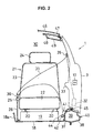
- FIG. 2 is an elevational view of the significant portion, when the door is in closed state.
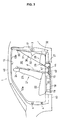
- FIG. 3 is an elevational view for assistance in explaining the movement of the belt webbing by the opening of the rear door.
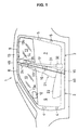
- FIG. 4 is an elevational view of the significant portion, when the rear door is open.
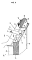
- FIG. 5 is a perspective view showing the construction of the sliding device.
- FIG. 6 is a cross-sectional view showing another embodiment of the sliding device.
- FIG. 7 is a side view of the vehicle equipped with the seat belt system according to the preferred embodiment of the present invention.
- FIG. 8 is an elevational view for assistance in explaining the movement of the belt webbing by the opening of the rear door.
- FIG. 9 is an elevational view of the significant portion, when the rear door is open.
- FIG. 10 is a perspective view showing the sliding device in a slanting manner.
-
- A preferred embodiment of the present invention will be described with reference to FIG. 1 to FIG. 5. Firstly, with reference to FIG. 1 to FIG. 4, a body structure and a door structure will be described.
- As shown in FIG. 1 and FIG. 3, side doors are disposed on the side portion of a body of a
vehicle 1. The side doors comprise of afront door 2 and arear door 3 which are supported on the side portion of a body of avehicle 1 via front-door hinges 4 and rear-door hinges 5 attached on the a leading edge of thefront door 2 and a trailing edge of therear door 3, respectively, constituting a side door structure in a double door configuration. Accordingly, thefront door 2 opens or pivots in a forward direction while therear door 3 opens or pivots in a backward direction, i.e. in a direction substantially opposite to that of thefront door 2. - The
front door 2 and therear door 3 comprisedoor panels door sashes door windows door panel 6 and door panel 7 (specifically, in the interspace defined by a door inner-panel and a door-outer panel), side impact bars extend substantially in the vehicular longitudinal direction, respectively. - On the
front door 2, aside mirror 12 for rearward visibility and an outside door-handle (not shown) for unlatch operation for thefront door 2 from the outside preferably are disposed. - In the double door configuration according to this embodiment, the
rear door 3 is prohibited from opening unless thefront door 2 opens. - Meanwhile, inboardly adjacent to the doors in the closed position, a front ingress and egress opening 13a for a front passenger and a rear ingress and egress opening 13b for a rear passenger as door openings (side openings of the vehicle) are continuously formed to provide a substantially
continuous opening 13, whereby a center-pillar-less or B-post-less body structure is attained. Theopenings doors - As shown in FIG. 1, at the forward portions of the upper and lower edge of the
rear door 3,locks rear door 3 with the body, and at the middle portion of the leading edge of therear door 3, alock 17 is provided for locking astriker 16 on thefront door 2. - On the other hand, as shown in FIG. 2 and FIG. 3, a
front seat 21 is mounted on afloor panel 18 viabrackets mechanism 20. Thefront seat 21 comprises aseat cushion 22, a seat back 23, and a head rest 24. Between theseat cushion 22 of thefront seat 21 and acenter tunnel 18a, abuckle 25 is fixedly secured to thefloor panel 18 via abracket 26. Alternatively, thebuckle 25 may be secured to the seat cushion via a stalk. - The rear portion of the
floor panel 18 is stepped or projected upwardly to integrally or unitarily form a kick-up or steppedportion 27. On the top of the kick-up 27, aseat cushion 29 of arear seat 28 is mounted. Thus, as shown in FIG. 3, in thepassenger compartment 30 of thevehicle 1, a plural row ofseats - FIG. 2 is a partial elevational view showing said
front seat 21 and therear door 3 in the closed state, and FIG. 4 is a partial elevational view showing therear door 3 in the open state and also depicting a belt-webbing or seat-belt orsafety belt system 31 for restraining the passenger to be positioned in thefront seat 21. - The
belt webbing 31 is retracted by aretractor 32 disposed on a front structural door-member 3a of therear door 3. The front structural door-member 3a has the equivalent rigidity to that of a center-pillar which would be provided. - The lower half of the inboard side of the
rear door 3 is covered with adoor trim 34 having anarm rest 33. On the other hand, at the upper portion of the inboard side of the front structural door-member 3a, ashoulder anchor 35 is attached so as to substantially face or correspond to the flank ofhead rest 24 of thefront seat 21. Theshoulder anchor 35 may be displaceably provided on thedoor member 3a substantially along a vertical direction. - The
belt webbing 31 is so arranged as to extend from theretractor 32 through the upper edge of the door trim 34 along the inboard side of the front structural door-member 3a, and reaches thepassenger compartment 30 through theshoulder anchor 35. In other words, theshoulder anchor 35 supports a portion of the extended length of thebelt webbing 31. - On the extended length of the
belt webbing 31, atongue 36 is slidably provided which can cooperate with thebuckle 25 to be locked or fixed thereto. The distal end, or the lower end of thebelt webbing 31 is so connected to the lower edge of the door opening 13 as to be slidable in the vehicular longitudinal direction between a first position (corresponding to a front portion FP of aguide member 42 to be described later) and a second position (corresponding to a rear portion RP of theguide member 42 to be described later), as shown in FIG. 3. Subsequently, the sliding structure disposed on the lower end of thebelt webbing 31 will be described. - As shown in FIG. 5, along both lateral sides of the floor panel (the drawing shows one of them), a side sill or door sill or
rocker panel 40, which is a structural member and includes aclosed cross-section 39 defined by a side-sill inner 37 and side-sill outer 38, is disposed. Aguide member 42 as an element of a slidingdevice 41 is fixedly secured to the side-sill inner 37 of theside sill 40 via fasteners, for example, viabolts 43. Theguide member 42 preferably substantially has a bridge-like shape and comprises a slide portion for aslider 44 to be described later. - The sliding
device 41 is arranged between thebelt webbing 31 and the side-sill inner 37 as a lower edge of thedoor opening 13, and comprises theguide member 42 and aslider 44 slidable forwardly and rearwardly, or between a forward position and a rearward position on theguide member 42. Theslider 44 is integrally formed with a belt-attachingportion 44a at which the lower end of thebelt webbing 31 is fixedly attached. Thus, the lower end of thebelt webbing 31 is guided or slidably fixed by the slidingdevice 41 so as to slide substantially forwardly and rearwardly along the inboard side of theside sill 37. - In this embodiment shown in FIG. 5, the guide member is formed from a metallic cylindrical pipe. The pipe has bent portions near its ends, and both ends are processed into flat attaching portions which are secured to the side-sill inner 37 via the
bolts 43. - The
slider 44 is formed from a metallic cylindrical pipe, and slides along the peripheral surface of the straight portion of theguide member 42. The pipe has a projection bonded thereto or integrally or unitarily provided thereon, which preferably acts as abelt attaching portion 44a. - As shown by phantom lines α, when the
rear door 3 is in the closed state, thebelt webbing 31, theshoulder anchor 35, and thetongue 36 are so arranged as to substantially face or substantially correspond to the flank of the seat back 23 of thefront seat 21. When the front passenger pulls thebelt webbing 31 to fasten the seat belt, the lower portion of thebelt webbing 31 attached to theslider 44 is preferably caused to move towards thefront seat 21 along theguide member 42 up to a forward position. - Then, the engagement of the clasp at the tip of the
tongue 36 with thebuckle 25 results in the three-point seat belt restraint configuration for restraining the passenger in thefront seat 21. - On the other hand, when the
rear door 3 is opened after the front passenger unlatches theseat belt 31 and opens thefront door 2, the movement of therear door 3 pulls thebelt webbing 31 rearwardly. Accordingly, the lower portion of the belt webbing attached to theslider 44 moves to a rearward position along theguide member 42, causing no interference against the legs of the rear passenger in egress. This advantage is available in ingress likewise. - In the drawing, identified by 45, 46, 47, 48, and 49 are a scuffed plate e.g. made of resin, etc, a roof panel, a roof rail, a roof-rail outer, and roof-rail inner, respectively.
- As described above, according to the embodiment shown in FIG. 1 to FIG. 5, there is provided the seat belt system for the
vehicle 1, for restraining the passenger in theseat 21 disposed in the passenger compartment of thevehicle 1, thevehicle 1 including the door opening 13 formed on at least one side of the vehicular body, and adoor 3 moving between a first state where thedoor 3 closes at least a part of thedoor opening 13 and a second state where thedoor 3 opens at least part of thedoor opening 13, the seat belt system comprising, thebelt webbing 31, theretractor 32 disposed in or on or at thedoor 3, for retracting the proximal or first end of thebelt webbing 31, the slidingdevice 41 to which the distal or second end of thebelt webbing 31 is attached so that the distal end of thebelt webbing 31 is allowed to slide or glide substantially along the lower edge of the door opening 13 between a forward or first position (corresponding to the front portion FP of the guide member 42) and a rearward or second position (corresponding to a rearward part of the guide member 42). Preferably, the distal or second end of thebelt webbing 31 may be located at the rearward position when thedoor 3 is in the second state, and located at the forward position when thedoor 3 is in the first state. - Accordingly, the distal or second end portion of the
belt webbing 31 slides rearwardly to the rearward position substantially along the lower edge of the door opening 13 with the opening of thedoor 3, which enhances convenience of ingress and egress for the passengers,further preferably achieving the improved appearance of thebelt webbing 31 while thedoor 3 being open. Especially, it attains or improves the openness of the opening and improved accessibility for the legs of the passenger to the seat. - Additionally, the sliding
device 41 preferably comprises aguide member 42 disposed on or mounted to the lower edge of the door opening 13 so as to extend along the lower edge, and theslider 44 to which the distal end of thebelt webbing 31 is attached, fitting onto theguide member 42 slidably between the forward portion FP and the rearward portion RP of theguide member 42. - Accordingly, the distal end of the
belt webbing 31 slides or glides substantially along the lower edge of the door opening 13 according to the movement of thedoor 3 with the aid of theguide member 42 and theslider 44, which ensures the sliding of the distal end of thebelt webbing 31. - Further, the
shoulder anchor 35 is disposed on the upper portion of the inboard surface of thedoor 3 and supports the middle portion of thebelt webbing 31 between the distal or second end and the proximal or first end. Accordingly, theshoulder anchor 35 provides stable support for thebelt webbing 31 and the three-point seat belt restraint configuration for restraining the passenger. - Moreover, the
door 3 is swingably or pivotably supported on the vehicle body at its trailing or rearward edge via thehinge 5. Accordingly, the end portion of thebelt webbing 31 slides rearwardly to the rearward position for thevehicle 1 by the swing or pivotal movement of thedoor 3 about thehinge 5 on its rear portion. Thus, thebelt webbing 31 provides no interference against the legs of rear passenger in egress or in egress to enhance convenience of ingress and egress for the passengers. - Additionally, the vehicle comprises the
front door 2 disposed ahead of therear door 3 with being swinglably or pivotably supported on the vehicle body at its leading or front edge via thehinge 4, and thefront door 2 and therear door 3 cooperatively close thedoor opening 13. Accordingly, therear door 3 and thefront door 2 constitute a double door configuration, which attains the larger door opening 13 for efficient use. - Further, the
door opening 13 is a single opening continuously formed. Accordingly, a center-pillar-less or B-post-less structure, without a center-pillar or B-post, is attained in combination with the double door configuration, so that the enough openness of the door opening and the efficient use of the continuous opening (the door opening 13) are available. - Moreover, the vehicle comprises the
front seat 21 and therear seat 28, and the seat belt system is permitted to restrain an occupant, or a passenger in thefront seat 21 when therear door 3 is in the first state, or closed. Accordingly, the passenger on thefront seat 21 is reliably restrained by thebelt webbing 31 to improve safety. - Alternatively, the sliding
device 41 may be constituted as shown in FIG. 6. As shown in FIG. 6, the slidingdevice 41 comprises theguide member 42 formed from a cylindrical bar with a specified (predetermined or predeterminable) straight length, a ball-bush type slider 44 with anouter tube 50, aholder 51, a number of steel or bearingballs 52, and astopper ring 53. On theouter tube 50, abelt attaching portion 44a is fixed or integrally or unitarily formed, to which the lower end of thebelt webbing 31 is or can be attached. - According to the constitution above, friction of the
slider 44 in sliding motion during the movement of therear door 3 is reduced by a large amount, so that the lower end of thebelt webbing 31 slides more reliably and smoothly. Where necessary, stoppers such as E-rings, stopper rings, and stopper pins may be attached on the forward end and rearward end of theguide member 42. Alternatively or additionally, theslider 44 may be provided at its contact portion with theguide member 42 with a coating and/or a layer of friction-reducing material such as teflon. - Subsequently, another preferred embodiment of the present invention will now be described with reference to FIG. 7 to FIG. 10. The description on the same or similar constitution, action and advantage as those of the preceding embodiment is omitted, and the elements identical or similar to the ones in the preceding drawings are given identical numerals.
- In this embodiment shown in FIG. 7 to FIG. 10, the
guide member 42 slops down to the forward, or is slantingly disposed so that a rear end of theguide member 42 is disposed in a position higher than a front end thereof; preferably theguide member 42 is arranged with an end located at the side-sill inner 37 and the other end located at a top deck surface of the kick-up or step orprojection 27. Theslider 44 slidably fits onto the substantially straight portion of theguide member 42. - According to the construction, when the
rear door 3 is in the closed state, thebelt webbing 31 is shown as indicated by phantom lines α in FIG. 8. On the other hand, when therear door 3 is opened after thefront door 2 is opened, theslider 44 and the lower end of thebelt webbing 31 is pulled rearwardly along the inclined or slantingly-disposedguide member 42 until theslider 44 reaches the top surface of the kick-up 27 laterally adjacent to the flank of theseat cushion 29 of therear seat 28 as indicated by solid lines in FIG. 8. The rearward movement of theslider 44 is longer than that of the embodiment shown in FIG. 1 to FIG. 5, and causes no interference against the legs of the rear passenger in ingress and in egress. - As described above, in the seat belt system for the vehicle shown in FIG. 7 to FIG. 10, the sliding
device 41 comprises theguide member 42 fixed to the body and theslider 44 which slides on theguide member 42, the vehicular body includes the kick-up 27 stepped upwardly on which therear seat 28 is disposed, and the rearward portion of theguide member 42 is disposed laterally adjacent to therear seat 28 on the kick-up 27 and fixed thereto. Particularly, theguide member 42 is slantingly disposed with an end located at the side-sill inner 37 and the other end located at the top surface of the kick-up 27. Accordingly, the lower end of thebelt webbing 31 is guided by the slantingly-disposedguide member 42 andslider 44 to slide up to the vicinity of therear seat 28, or slide to a further rearward position, so that largely-improved convenience for the rear passenger in ingress and egress is attained. - It should be appreciated that the constitution shown in FIG. 6 may adopted to the sliding
device 41 shown in FIG. 7 to FIG. 10.
Claims (10)
- A seat belt system for a vehicle (1), for restraining an occupant in a seat (21) disposed in a passenger compartment of the vehicle (1), the vehicle (1) including an opening (13) formed on at least one side of a vehicular body, wherein the seat belt system comprises,
a belt webbing (31),
a retractor (32) to be disposed at a first door (3) of the vehicle (1) for retracting a first end of said belt webbing (31),
a sliding means (41) to be fixed on a lower edge (37) of the opening (13), to which a second end of said belt webbing (31) is attached so that the second end of said belt webbing (31) is allowed to slide along a lower edge (37) of the opening (13) at least between a first position (FP) and a second position (RP). - A seat belt system for a vehicle (1) as defined in claim 1, said sliding means (41) comprising:a guide member (42) to be disposed on the lower edge (37) of the opening (13) so as to at least partly extend along the lower edge (37), anda slider (44) to which the second end of said belt webbing (31) is attached, the slider (44) being mounted to said guide member (42) so as to be slidable between the first position (FP), preferably corresponding to a forward portion (FP) of the guide member (42), and the second position (RP), preferably corresponding to a rearward portion (FP) of the guide member (42).
- A seat belt system for a vehicle (1) as defined in claim 2, wherein the vehicle (1) includes a first door (3) movable between a first state where the first door (3) closes at least a part of the opening (13) and a second state where the first door (3) opens the opening (13), and wherein said slider (44) is to be located at the second position (RP), preferably at the rearward portion (RP) of the guide member (42), when the first door (3) is in the second state and is to be located at the first position (FP), preferably at the forward portion (FP) of the guide member (42), when the first door (3) is in the first state.
- A seat belt system for a vehicle (1) according to claim 2 or 3, wherein the guide member (42) is to be mounted in an inclined orientation on the lower edge (37) of the opening.
- A seat belt system for a vehicle (1) as defined in one or more of the preceding claims, further comprising a shoulder anchor (35) to be disposed on an upper portion of an inboard surface of the first door (3), wherein the shoulder anchor (35) supports a middle portion of said belt webbing (31) between the second end and the first end thereof.
- A vehicle (1) including an opening (13) formed on at least one side of a vehicular body and a first door (3) movable between a first state where the first door (3) closes at least a part of the opening (13) and a second state where the first door (3) opens the opening (13), wherein the vehicle (1) comprises a seat belt system according to one or more of the preceding claims.
- A vehicle (1) as defined in claim 5, wherein the first door (3) is swingably supported on the vehicular body at its trailing edge via at least one first hinge (5).
- A vehicle (1) as defined in claim 6, the vehicle comprising a second door (2) disposed ahead of the first door (3) with being swinglably supported on the vehicle body at its leading edge via at least one second hinge (4), wherein the first door (3) and the second door (2) cooperatively close the opening (13), wherein the opening (13) preferably is a single opening continuously formed.
- A vehicle (1) as defined in one of the preceding claims 5 to 8, comprising a front seat (21) and a rear seat (28), wherein said seat belt system is permitted to restrain an occupant in the front seat (21) when the first door (3) is in the first state.
- A vehicle (1) as defined in one of the preceding claims 5 to 9, wherein the vehicular body includes a kick-up portion (27) stepped upwardly on which the rear seat (28) is to be disposed, and wherein the rearward portion (RP) of the guide member (42) is located laterally adjacent to the rear seat (28) on or at the kick-up portion (27).
Applications Claiming Priority (2)
| Application Number | Priority Date | Filing Date | Title |
|---|---|---|---|
| JP2001095620 | 2001-03-29 | ||
| JP2001095620A JP4710156B2 (en) | 2001-03-29 | 2001-03-29 | Vehicle seat belt structure |
Publications (2)
| Publication Number | Publication Date |
|---|---|
| EP1247703A1 true EP1247703A1 (en) | 2002-10-09 |
| EP1247703B1 EP1247703B1 (en) | 2006-05-31 |
Family
ID=18949640
Family Applications (1)
| Application Number | Title | Priority Date | Filing Date |
|---|---|---|---|
| EP02006642A Expired - Lifetime EP1247703B1 (en) | 2001-03-29 | 2002-03-25 | Seat belt system for vehicles and vehicle provided therewith |
Country Status (4)
| Country | Link |
|---|---|
| US (1) | US6698795B2 (en) |
| EP (1) | EP1247703B1 (en) |
| JP (1) | JP4710156B2 (en) |
| DE (1) | DE60211788T2 (en) |
Cited By (3)
| Publication number | Priority date | Publication date | Assignee | Title |
|---|---|---|---|---|
| EP1336539A1 (en) * | 2002-02-18 | 2003-08-20 | Mazda Motor Corporation | seat belt system for vehicles and vehicle provided therewith |
| EP1340641A1 (en) * | 2002-02-27 | 2003-09-03 | Mazda Motor Corporation | Double door construction for vehicles |
| EP2933191A1 (en) * | 2014-04-15 | 2015-10-21 | Airbus Operations GmbH | Seat belt arrangement and seat assembly incorporating same |
Families Citing this family (6)
| Publication number | Priority date | Publication date | Assignee | Title |
|---|---|---|---|---|
| JP3709853B2 (en) * | 2002-03-28 | 2005-10-26 | マツダ株式会社 | Car seat belt equipment |
| US7416218B2 (en) * | 2003-01-24 | 2008-08-26 | Takata Corporation | Seat belt device |
| US7537242B2 (en) * | 2003-01-24 | 2009-05-26 | Takata Corporation | Seat belt device |
| US8550499B2 (en) | 2010-12-09 | 2013-10-08 | Autoliv Asp, Inc. | Pyrotechnic lap belt pretensioner with slider bar function |
| US10246045B2 (en) * | 2017-05-03 | 2019-04-02 | Ford Global Technologies, Llc | Harness bar assembly |
| US11180110B2 (en) * | 2018-09-12 | 2021-11-23 | Ford Global Technologies, Llc | Vehicle buckle assembly |
Citations (11)
| Publication number | Priority date | Publication date | Assignee | Title |
|---|---|---|---|---|
| US3819196A (en) * | 1972-08-31 | 1974-06-25 | Peugeot & Renault | Automatic safety harness control system |
| US4007802A (en) * | 1974-07-24 | 1977-02-15 | Regie Nationale Des Usines Renault | Remote control device for safety harness webbing winder |
| JPS554248A (en) * | 1978-06-27 | 1980-01-12 | Takata Kk | Belt guide |
| FR2474413A1 (en) * | 1980-01-29 | 1981-07-31 | Renault | Mobile lap anchor for car seat belt - has rail mounted anchor moved during rear seat folding to maintain safety belt angle |
| EP0041859A1 (en) * | 1980-06-10 | 1981-12-16 | Ase (Uk) Limited | Vehicle seat belt connection device |
| DE3539051A1 (en) * | 1984-11-06 | 1986-05-15 | Volkswagen AG, 3180 Wolfsburg | Safety belt arrangement |
| JPS63222957A (en) * | 1987-03-12 | 1988-09-16 | Mazda Motor Corp | Seat belt device of automobile |
| US4909539A (en) * | 1985-11-14 | 1990-03-20 | Autoliv Development Ab | Safety belt system |
| FR2646641A1 (en) * | 1989-05-03 | 1990-11-09 | Renault | Device for controlling a seat belt along a track |
| US5044459A (en) * | 1988-10-26 | 1991-09-03 | Mazda Motor Corporation | Automobile seat belt apparatus |
| JP2001138864A (en) * | 1999-11-11 | 2001-05-22 | Toyota Autom Loom Works Ltd | Automotive seat belt equipment |
Family Cites Families (22)
| Publication number | Priority date | Publication date | Assignee | Title |
|---|---|---|---|---|
| US2997336A (en) * | 1959-03-13 | 1961-08-22 | Chrysler Corp | Side loading suburban vehicle |
| SE424812B (en) * | 1980-06-18 | 1982-08-16 | Stil Ind Ab | DEVICE AT THE VEHICLE SEAT BELT |
| JPS5853546A (en) * | 1981-09-28 | 1983-03-30 | Honda Motor Co Ltd | Seat belt device for vehicle |
| JPS5869582A (en) * | 1981-10-22 | 1983-04-25 | 日産自動車株式会社 | Seat belt apparatus |
| JPS60143055U (en) * | 1984-03-06 | 1985-09-21 | 富士機工株式会社 | Slide bar mounting device |
| JPS61229643A (en) * | 1985-04-03 | 1986-10-13 | Nissan Motor Co Ltd | Passive seat belt device |
| JPS6317146A (en) * | 1986-07-07 | 1988-01-25 | Mazda Motor Corp | Seat belt device for automobile |
| JPS63130450A (en) | 1986-11-17 | 1988-06-02 | Mazda Motor Corp | Seatbelt device for automobile |
| US4817754A (en) * | 1987-04-27 | 1989-04-04 | Mazda Motor Corporation | Automotive seat belt system and retractor device for seat belt system |
| SE456983B (en) * | 1987-05-08 | 1988-11-21 | Autoliv Dev | FLOOR FIXED FOODS AND A SAFETY BALANCE OF THREE-POINT TYPE |
| JP2537624B2 (en) * | 1987-05-16 | 1996-09-25 | マツダ株式会社 | Automobile seat belt device |
| JPH02114562U (en) * | 1989-02-28 | 1990-09-13 | ||
| JPH0733933Y2 (en) * | 1989-06-23 | 1995-08-02 | スズキ株式会社 | Door trim structure for passive seat belts |
| JPH0740438Y2 (en) * | 1989-06-23 | 1995-09-20 | スズキ株式会社 | Passive seat belt mounting structure |
| JPH0347260U (en) * | 1989-09-13 | 1991-05-01 | ||
| JPH0347262U (en) * | 1989-09-18 | 1991-05-01 | ||
| JPH0365961U (en) * | 1989-10-31 | 1991-06-26 | ||
| JPH0474161U (en) * | 1990-11-09 | 1992-06-29 | ||
| JPH068937Y2 (en) * | 1991-03-08 | 1994-03-09 | マツダ株式会社 | Vehicle seat belt arrangement structure |
| JPH08142680A (en) | 1994-11-25 | 1996-06-04 | Nissan Shatai Co Ltd | Kannon door |
| JP2001026218A (en) * | 1999-07-14 | 2001-01-30 | Mazda Motor Corp | Vehicle side door structure |
| JP2001027067A (en) * | 1999-07-14 | 2001-01-30 | Mazda Motor Corp | Hinge structure of vehicle side door |
-
2001
- 2001-03-29 JP JP2001095620A patent/JP4710156B2/en not_active Expired - Lifetime
-
2002
- 2002-03-25 DE DE60211788T patent/DE60211788T2/en not_active Expired - Lifetime
- 2002-03-25 EP EP02006642A patent/EP1247703B1/en not_active Expired - Lifetime
- 2002-03-28 US US10/107,542 patent/US6698795B2/en not_active Expired - Lifetime
Patent Citations (11)
| Publication number | Priority date | Publication date | Assignee | Title |
|---|---|---|---|---|
| US3819196A (en) * | 1972-08-31 | 1974-06-25 | Peugeot & Renault | Automatic safety harness control system |
| US4007802A (en) * | 1974-07-24 | 1977-02-15 | Regie Nationale Des Usines Renault | Remote control device for safety harness webbing winder |
| JPS554248A (en) * | 1978-06-27 | 1980-01-12 | Takata Kk | Belt guide |
| FR2474413A1 (en) * | 1980-01-29 | 1981-07-31 | Renault | Mobile lap anchor for car seat belt - has rail mounted anchor moved during rear seat folding to maintain safety belt angle |
| EP0041859A1 (en) * | 1980-06-10 | 1981-12-16 | Ase (Uk) Limited | Vehicle seat belt connection device |
| DE3539051A1 (en) * | 1984-11-06 | 1986-05-15 | Volkswagen AG, 3180 Wolfsburg | Safety belt arrangement |
| US4909539A (en) * | 1985-11-14 | 1990-03-20 | Autoliv Development Ab | Safety belt system |
| JPS63222957A (en) * | 1987-03-12 | 1988-09-16 | Mazda Motor Corp | Seat belt device of automobile |
| US5044459A (en) * | 1988-10-26 | 1991-09-03 | Mazda Motor Corporation | Automobile seat belt apparatus |
| FR2646641A1 (en) * | 1989-05-03 | 1990-11-09 | Renault | Device for controlling a seat belt along a track |
| JP2001138864A (en) * | 1999-11-11 | 2001-05-22 | Toyota Autom Loom Works Ltd | Automotive seat belt equipment |
Non-Patent Citations (3)
| Title |
|---|
| PATENT ABSTRACTS OF JAPAN vol. 004, no. 029 (M - 002) 14 March 1980 (1980-03-14) * |
| PATENT ABSTRACTS OF JAPAN vol. 013, no. 013 (M - 783) 12 January 1989 (1989-01-12) * |
| PATENT ABSTRACTS OF JAPAN vol. 2000, no. 22 9 March 2001 (2001-03-09) * |
Cited By (6)
| Publication number | Priority date | Publication date | Assignee | Title |
|---|---|---|---|---|
| EP1336539A1 (en) * | 2002-02-18 | 2003-08-20 | Mazda Motor Corporation | seat belt system for vehicles and vehicle provided therewith |
| US6824167B2 (en) | 2002-02-18 | 2004-11-30 | Mazda Motor Corporation | Seat belt system for vehicles |
| EP1340641A1 (en) * | 2002-02-27 | 2003-09-03 | Mazda Motor Corporation | Double door construction for vehicles |
| US6808225B2 (en) | 2002-02-27 | 2004-10-26 | Mazda Motor Corporation | Double door construction for vehicle |
| EP2933191A1 (en) * | 2014-04-15 | 2015-10-21 | Airbus Operations GmbH | Seat belt arrangement and seat assembly incorporating same |
| US10279914B2 (en) | 2014-04-15 | 2019-05-07 | Airbus Operations Gmbh | Seat belt arrangement and seat assembly incorporating same |
Also Published As
| Publication number | Publication date |
|---|---|
| DE60211788T2 (en) | 2007-05-24 |
| JP2002283955A (en) | 2002-10-03 |
| US6698795B2 (en) | 2004-03-02 |
| JP4710156B2 (en) | 2011-06-29 |
| DE60211788D1 (en) | 2006-07-06 |
| EP1247703B1 (en) | 2006-05-31 |
| US20020167158A1 (en) | 2002-11-14 |
Similar Documents
| Publication | Publication Date | Title |
|---|---|---|
| US8336914B2 (en) | Seatbelt device of vehicle | |
| US6113191A (en) | Storable seat assembly | |
| EP1582397A1 (en) | Seat device for a vehicle and vehicle provided therewith | |
| EP1247703B1 (en) | Seat belt system for vehicles and vehicle provided therewith | |
| US6824167B2 (en) | Seat belt system for vehicles | |
| EP1285824B1 (en) | Seat belt system for a vehicle | |
| US7364200B2 (en) | Vehicle seatbelt restraining apparatus | |
| US4354695A (en) | Seat belt system | |
| JP2002087206A (en) | Vehicle seat belt storage structure | |
| JP3915492B2 (en) | Vehicle seat belt device | |
| JP2003237369A (en) | Vehicle door structure | |
| US4225156A (en) | Passive restraint belt system | |
| JPH0724293Y2 (en) | Car seat belt equipment | |
| JPH0754042Y2 (en) | Seatbelt device for automobile | |
| JP4582434B2 (en) | Vehicle seat belt structure | |
| JP4296953B2 (en) | Vehicle seat belt device | |
| US4047737A (en) | Seat belt system for motor cars | |
| JP4596301B2 (en) | Vehicle seat belt structure | |
| JP4596302B2 (en) | Vehicle seat belt structure | |
| JP5077417B2 (en) | Vehicle seat belt structure | |
| US4094533A (en) | Seatbelt system for motor cars | |
| JP2589763B2 (en) | Automotive seat belt equipment | |
| JPH10250438A (en) | Seat unlocking device for car seats | |
| JP2004148939A (en) | Vehicle interior material distribution structure | |
| JPH0366178B2 (en) |
Legal Events
| Date | Code | Title | Description |
|---|---|---|---|
| PUAI | Public reference made under article 153(3) epc to a published international application that has entered the european phase |
Free format text: ORIGINAL CODE: 0009012 |
|
| AK | Designated contracting states |
Kind code of ref document: A1 Designated state(s): AT BE CH CY DE DK ES FI FR GB GR IE IT LI LU MC NL PT SE TR |
|
| AX | Request for extension of the european patent |
Free format text: AL;LT;LV;MK;RO;SI |
|
| 17P | Request for examination filed |
Effective date: 20030109 |
|
| AKX | Designation fees paid |
Designated state(s): DE ES FR GB IT |
|
| 17Q | First examination report despatched |
Effective date: 20041018 |
|
| GRAP | Despatch of communication of intention to grant a patent |
Free format text: ORIGINAL CODE: EPIDOSNIGR1 |
|
| GRAS | Grant fee paid |
Free format text: ORIGINAL CODE: EPIDOSNIGR3 |
|
| GRAA | (expected) grant |
Free format text: ORIGINAL CODE: 0009210 |
|
| AK | Designated contracting states |
Kind code of ref document: B1 Designated state(s): DE ES FR GB IT |
|
| PG25 | Lapsed in a contracting state [announced via postgrant information from national office to epo] |
Ref country code: IT Free format text: LAPSE BECAUSE OF FAILURE TO SUBMIT A TRANSLATION OF THE DESCRIPTION OR TO PAY THE FEE WITHIN THE PRESCRIBED TIME-LIMIT;WARNING: LAPSES OF ITALIAN PATENTS WITH EFFECTIVE DATE BEFORE 2007 MAY HAVE OCCURRED AT ANY TIME BEFORE 2007. THE CORRECT EFFECTIVE DATE MAY BE DIFFERENT FROM THE ONE RECORDED. Effective date: 20060531 |
|
| REG | Reference to a national code |
Ref country code: GB Ref legal event code: FG4D |
|
| REF | Corresponds to: |
Ref document number: 60211788 Country of ref document: DE Date of ref document: 20060706 Kind code of ref document: P |
|
| PG25 | Lapsed in a contracting state [announced via postgrant information from national office to epo] |
Ref country code: ES Free format text: LAPSE BECAUSE OF FAILURE TO SUBMIT A TRANSLATION OF THE DESCRIPTION OR TO PAY THE FEE WITHIN THE PRESCRIBED TIME-LIMIT Effective date: 20060911 |
|
| PLBE | No opposition filed within time limit |
Free format text: ORIGINAL CODE: 0009261 |
|
| STAA | Information on the status of an ep patent application or granted ep patent |
Free format text: STATUS: NO OPPOSITION FILED WITHIN TIME LIMIT |
|
| EN | Fr: translation not filed | ||
| 26N | No opposition filed |
Effective date: 20070301 |
|
| GBPC | Gb: european patent ceased through non-payment of renewal fee |
Effective date: 20070325 |
|
| PG25 | Lapsed in a contracting state [announced via postgrant information from national office to epo] |
Ref country code: GB Free format text: LAPSE BECAUSE OF NON-PAYMENT OF DUE FEES Effective date: 20070325 Ref country code: FR Free format text: LAPSE BECAUSE OF FAILURE TO SUBMIT A TRANSLATION OF THE DESCRIPTION OR TO PAY THE FEE WITHIN THE PRESCRIBED TIME-LIMIT Effective date: 20070309 |
|
| PG25 | Lapsed in a contracting state [announced via postgrant information from national office to epo] |
Ref country code: FR Free format text: LAPSE BECAUSE OF FAILURE TO SUBMIT A TRANSLATION OF THE DESCRIPTION OR TO PAY THE FEE WITHIN THE PRESCRIBED TIME-LIMIT Effective date: 20060531 |
|
| PGFP | Annual fee paid to national office [announced via postgrant information from national office to epo] |
Ref country code: DE Payment date: 20210310 Year of fee payment: 20 |
|
| REG | Reference to a national code |
Ref country code: DE Ref legal event code: R071 Ref document number: 60211788 Country of ref document: DE |