EP1582397A1 - Seat device for a vehicle and vehicle provided therewith - Google Patents
Seat device for a vehicle and vehicle provided therewith Download PDFInfo
- Publication number
- EP1582397A1 EP1582397A1 EP05004131A EP05004131A EP1582397A1 EP 1582397 A1 EP1582397 A1 EP 1582397A1 EP 05004131 A EP05004131 A EP 05004131A EP 05004131 A EP05004131 A EP 05004131A EP 1582397 A1 EP1582397 A1 EP 1582397A1
- Authority
- EP
- European Patent Office
- Prior art keywords
- seat
- assistant
- vehicle
- row
- rail member
- Prior art date
- Legal status (The legal status is an assumption and is not a legal conclusion. Google has not performed a legal analysis and makes no representation as to the accuracy of the status listed.)
- Granted
Links
Images


Classifications
-
- B—PERFORMING OPERATIONS; TRANSPORTING
- B60—VEHICLES IN GENERAL
- B60N—SEATS SPECIALLY ADAPTED FOR VEHICLES; VEHICLE PASSENGER ACCOMMODATION NOT OTHERWISE PROVIDED FOR
- B60N2/00—Seats specially adapted for vehicles; Arrangement or mounting of seats in vehicles
- B60N2/005—Arrangement or mounting of seats in vehicles, e.g. dismountable auxiliary seats
- B60N2/01—Arrangement of seats relative to one another
-
- B—PERFORMING OPERATIONS; TRANSPORTING
- B60—VEHICLES IN GENERAL
- B60N—SEATS SPECIALLY ADAPTED FOR VEHICLES; VEHICLE PASSENGER ACCOMMODATION NOT OTHERWISE PROVIDED FOR
- B60N2/00—Seats specially adapted for vehicles; Arrangement or mounting of seats in vehicles
- B60N2/02—Seats specially adapted for vehicles; Arrangement or mounting of seats in vehicles the seat or part thereof being movable, e.g. adjustable
- B60N2/04—Seats specially adapted for vehicles; Arrangement or mounting of seats in vehicles the seat or part thereof being movable, e.g. adjustable the whole seat being movable
- B60N2/06—Seats specially adapted for vehicles; Arrangement or mounting of seats in vehicles the seat or part thereof being movable, e.g. adjustable the whole seat being movable slidable
- B60N2/07—Slide construction
- B60N2/0735—Position and orientation of the slide as a whole
-
- B—PERFORMING OPERATIONS; TRANSPORTING
- B60—VEHICLES IN GENERAL
- B60N—SEATS SPECIALLY ADAPTED FOR VEHICLES; VEHICLE PASSENGER ACCOMMODATION NOT OTHERWISE PROVIDED FOR
- B60N2/00—Seats specially adapted for vehicles; Arrangement or mounting of seats in vehicles
- B60N2/24—Seats specially adapted for vehicles; Arrangement or mounting of seats in vehicles for particular purposes or particular vehicles
- B60N2/30—Non-dismountable or dismountable seats storable in a non-use position, e.g. foldable spare seats
- B60N2/3038—Cushion movements
- B60N2/304—Cushion movements by rotation only
- B60N2/3045—Cushion movements by rotation only about transversal axis
-
- B—PERFORMING OPERATIONS; TRANSPORTING
- B60—VEHICLES IN GENERAL
- B60N—SEATS SPECIALLY ADAPTED FOR VEHICLES; VEHICLE PASSENGER ACCOMMODATION NOT OTHERWISE PROVIDED FOR
- B60N2/00—Seats specially adapted for vehicles; Arrangement or mounting of seats in vehicles
- B60N2/24—Seats specially adapted for vehicles; Arrangement or mounting of seats in vehicles for particular purposes or particular vehicles
- B60N2/30—Non-dismountable or dismountable seats storable in a non-use position, e.g. foldable spare seats
- B60N2/3038—Cushion movements
- B60N2/3054—Cushion movements by translation only
- B60N2/3056—Cushion movements by translation only along longitunal axis
Definitions
- the present invention relates to a seat device for a vehicle, in which there are provided a front-row seat and a rear-row seat in a cabin which includes an ingress and/or egress opening at a side face, and to a vehicle provided therewith.
- a seat slide device of an automotive vehicle in which a movement range of a first-rear-row seat and a second-rear-row seat, which are supported so as to be moved in a longitudinal direction of the vehicle along a rail member, is enlarged so as to increase the seat arrangement patterns, by locating seat backs of the first-rear-row and second-rear-row seats in their upright positions for sitting, in their rearward-reclined flat positions and in their forward-folded positions, respectively.
- the above-described structure, as disclosed in the latter patent publication, in which the first-rear-row seat is moved rearward closely to the font end of the second-rear-row seat, has advantage that a relatively large and useful space can be provided between the foremost driver seat or assistant seat and the first-rear-row seat and this space can be used properly.
- the rearward-movement range of the first-rear-row seat is so limited by the front end portion of the second-rear-row seat that the first-rear-row could not be moved rearward further sufficiently, it would be required that the seat arrangement patterns of passenger seats is increased.
- the present invention has been devised in view of the above-described problems, and an object of the present invention is to provide utilize a space in the cabin properly and provide a large and useful space for a passenger sitting on a front-row seat.
- a seat device for a vehicle comprising a front-row seat including a driver seat and an assistant seat, a rear-row seat provided behind the front-row seat, respective front-row and rear-row seats being provided in a cabin which includes an ingress and/or egress opening at a side face, wherein the rear-row seat is configured so as to be respectively located in a normal use position and in a stored position where a longitudinal thickness or dimension or extension thereof is made short or reduced (as compared to the normal use position), and the assistant seat is configured so as to be moved rearward from a position beside the driver seat to a position which corresponds to or near or close to the normal use position of the rear-row seat.
- a seat device for a vehicle which can utilize a space in the cabin properly, by effectively enlarging a rearward-movement range of the front-row seat including the assistant seat with a simple structure, and provide a large and useful space for a passenger sitting on the front-row seat. Accordingly, since the rearward-movement range of the assistant seat is enlarged without having any complicated operations such as a removal of the rear-row seat behind the assistant seat and the assistant seat is moved rearward to the position corresponding to or close to the normal use state of the rear-row seat, there can be provided properly the large and useful space beside the driver seat and before the assistant seat.
- the rear-row seat is configured such that the longitudinal thickness or dimension or extension thereof is made short with a seat cushion of the rear-row seat being rotated or pivoted or folded upward.
- the longitudinal thickness or dimension or extension of the rear-row seat behind the assistant seat can be made short (as compared to the normal use position) and the rearward-movement of the assistant seat can be extremely enlarged, by just rotating the seat cushion of the rear-row seat upward.
- the rear-row seat is configured so as to be further located in a lower stored position with a seat back of the rear-row seat being folded on the seat cushion of the rear-row seat, whereby the assistant seat can be moved rearward further when the rear-row seat is located in the lower stored position.
- the larger space can be formed beside the driver seat and before the assistant seat, by moving the assistant seat rearward when the rear-row seat is located in the lower stored position with its seat back being folded on its seat cushion.
- a plurality of independent rear seats and the independent rear seats are configured so as to be located in stored positions thereof separately.
- the independent rear seat behind the driver seat remains in the normal use position
- the assistant seat in the stored position is moved rearward to the position corresponding to or close to the normal use position of the independent rear seat in the stored position, and the assistant seat is located substantially beside the independent rear seat.
- plural passengers can sit substantially side by side on the assistant seat and the independent rear seat, with the large space formed in front of the assistant seat.
- a substantially continuous sitting face is formed by a seat cushion of the assistant seat and a seat cushion of the independent rear seat behind the driver seat when another independent rear seat behind the assistant seat is located in the stored position and the assistant seat is moved rearward, whereby the seat cushion of the assistant seat and the seat cushion of the independent rear seat can be located close to each other, preferably at substantially the same level (in the longitudinal direction and/or the vertical direction).
- the both seat cushions of the assistant seat and the independent rear seat behind the driver seat are used integrally so as to create the substantially continuous sitting face thereby, the seat utility of the vehicle can be improved effectively.
- the assistant seat is configured so as to be located in a stored position where a longitudinal thickness or dimension or extension thereof is made short with a seat cushion of the assistant seat being rotated or pivoted or folded upward.
- the longitudinal thickness or dimension or extension of the assistant seat is made short by rotating or pivoting or folding the seat cushion of the assistant seat upward, patterns of seat arrangement of the passenger seats can be increased effectively.
- the assistant seat located in the stored position is configured so as to be moved forward toward or closely to an instrument panel.
- a child seat is available or provided on the assistant seat.
- a proper seat arrangement which would make it easy for the passenger sitting on the independent rear seat behind the driver seat to take care of a child in the child seat, by moving the assistant seat equipped with the child seat to the position corresponding to or close to the normal use position of the independent rear seat behind the assistant seat. Also, the safety of the child seat can be improved by locating the child seat at the rear of the vehicle.
- a seat belt mechanism which is configured so as to be (selectively) applicable to passengers sitting on the rear-row seat and the assistant seat located in the rearward-moved position.
- the single seat belt mechanism protects or can be used for both passengers sitting on the rear-row seat in the normal use position and the assistant seat located in the rearward-movement position, the protection of passengers can be properly and easily attained.
- the belt mechanism comprises a retractor which retracts a seat belt, an anchor which supports the seat belt from the retractor at an upper side of the vehicle, and a buckle which fixes a front end of the seat belt to a vehicle body, and the seat belt mechanism is located so as to protect the passengers sitting on the rear-row seat and the assistant seat located in the rearward-moved position.
- the passenger sitting on the rear-row seat behind the assistant seat can be protected by the seat belt mechanism in which the seat belt from the retractor is supported by the anchor provided at the upper side of the vehicle and the front end of the seat belt is fixed to the vehicle body by the buckle. Also, when the assistant seat is moved rearward closely to the rear-row seat, the passenger sitting on the assistant seat can be also protected by the same seat belt mechanism.
- a seat rail member which supports the assistant seat so as to move the assistant seat rearward from the position beside the driver seat to the position which corresponds to or is close or near to the normal use position of the rear-row seat.
- the assistant seat is moved rearward closely to the rear-row seat along the seat rail member without having any complicated operations such as the removal of the rear-row seat, there can be provided the large and useful space effectively beside the driver seat and before the assistant seat.
- the seat rail member includes a seat rail member to support an outside edge portion of the assistant seat, and the seat rail member supporting the outside edge portion of the assistant seat is provided at a side sill which extends substantially in a longitudinal direction of the vehicle at a side portion of the vehicle.
- the seat rail member supporting the outside edge portion of the assistant seat is provided at the side sill as the rigidity member which extends in the longitudinal direction at the side portion of the vehicle, the sufficient supporting rigidity of the seat rail member can be ensured, and the side sill can be reinforced effectively by, for example, welding the seat rail member to the side sill.
- the seat rail member supporting the outside edge portion of the assistant seat is at least partly located in a recess portion which is formed at an inner panel of the side sill.
- the seat rail member is located in the recess portion formed at the inner panel of the side sill, the disposition of the seat rail member can be made stable effectively, and also the seat rail member can be prevented from projecting from the side sill so as to improve the passenger's getting on and off.
- the recess portion which is formed at the inner panel of the side sill is used as the seat rail member supporting the outside edge portion of the assistant seat.
- the recess portion formed at the inner panel of the side sill is used as the seat rail member supporting the outside edge portion of the assistant seat, the structure can be made simpler and lighter.
- the seat rail member includes a seat rail member to be provided at a portion of a floor panel, at which a floor frame which extends substantially in a longitudinal direction of the vehicle is provided.
- the seat rail member to be provided at the portion of the floor panel at which the floor frame extending substantially in the longitudinal direction is provided, the sufficient supporting rigidity of the seat rail member can be ensured.
- a floor cross member which extends substantially in a vehicle width direction (i.e. a direction at an angle different from 0° or 180°, preferably substantially normal to the longitudinal direction) is provided at or on a lower face of the floor panel.
- the floor cross member is provided at the lower face of the floor panel, the rigidity of the floor panel which even supports the seat rail member thereon can be increased effectively.
- the seat rail member includes a seat rail member to support an inside edge portion of the assistant seat, and the seat rail member supporting the inside edge portion of the assistant seat is provided at or on a tunnel portion which extends substantially in the longitudinal direction of the vehicle at a central portion of the vehicle.
- the seat rail member supporting the inside edge portion of the assistant seat is provided at the tunnel portion as the rigidity member which extends substantially in the longitudinal direction at the central portion of the vehicle, the sufficient supporting rigidity of the seat rail member can be ensured, and the tunnel portion can be reinforced by the seat rail member so as to improve its rigidity by welding the seat rail member to the tunnel portion.
- a drive mechanism which moves the rear-row seat to the stored position along with a rearward-movement operation of the assistant seat.
- the rear-row seat is located in the stored position with the short longitudinal thickness by moving rearward the assistant seat and the rearward-movement range of the assistant seat is enlarged without having any complicated operations such as the removal of the rear-row seat behind the assistant seat. Also, the assistant seat is moved rearward to the position corresponding to the normal use position of the rear-row seat. Thus, there can be provided properly the large and useful space beside the driver seat and before the assistant seat.
- a stopper mechanism which limits the rearward movement of the assistant seat at a point which is close to a seat cushion of the rear-row seat located in the normal use position.
- the assistant seat can be prevented from contacting knees or the like of the passenger sitting on the rear-row seat.
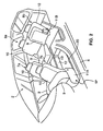
- FIG. 1 through 5 illustrate schematic views of a vehicle including a seat device for a vehicle according to a preferred embodiment of the present invention.
- the vehicle illustrated preferably is a so-called minivan type of vehicle, in which a cabin or passenger compartment 2 including a plurality of ingress and egress openings 1a and 1b preferably equipped with a front door and a rear door at its side face is provided between a front-wheel axle 3 and a rear-wheel axle 4.
- a floor panel 5 between right and left side sills 6, 6 in the cabin 2, and one or more, preferably a plurality of passenger seats 7 and 8 are (directly or indirectly) provided on the floor panel 5.
- a front-row seat 7 preferably comprising a driver seat 7a and an assistant seat 7b is disposed at a front portion of the floor panel 5, and a rear-row seat 8 preferably comprising a pair of independent seats 8a and 8b which are disposed substantially side by side is disposed behind the front-row seat 7.
- Each of the passenger seats 7 and 8 comprises a seat cushion 9 and a seat back 10.
- At least the assistant seat 7b and the rear seat (hereinafter, referred to as "assistant-seat-side rear seat") 8b, which is located just behind the assistant seat 7b, include support members 11A and 11B which pivotally support respective seat cushions 9, 9.
- these seat cushions 9, 9 of the assistant seat 7b and the assistant-seat-side rear seat 8b are configured so as to be located in their use positions, where they are disposed substantially horizontally as illustrated in FIG. 1, and in their stored or folded positions SP, where they are rotated or pivoted upward and folded with a short longitudinal thickness or extension or dimension as illustrated in FIG. 2.
- a tunnel portion 12 which projects substantially upward so as to extend substantially in the longitudinal direction of the vehicle and whose both ends preferably are fixed to inside faces of the above-described side sills 6, 6.
- a pair of floor frames 14, 14 extending preferably substantially in the longitudinal direction at right and left sides, whose front ends are connected integrally or unitarily with front side frames 15, 15 respectively which are at least partly disposed in an engine room located at the front of vehicle.
- a pair of front and rear floor cross members 16, 16 and 17, 17 is fixed to the upper face of the floor panel 5 so as to interconnect the tunnel portion 12 and the side sills 6 , 6 .
- a fuel tank 18 is at least partly disposed below the tunnel portion 12, preferably substantially extending in the longitudinal direction (see FIG. 5).
- the upper face of the tunnel portion 12 includes a recess portion 12a at or near one side edge thereof (the one edge at or toward a side of assistant seat 7b ), in which a seat rail member 19 to support an inside edge portion of the assistant seat 7b is disposed.
- Each of the side sills 6 , 6 forms a preferably closed cross section extending substantially in the longitudinal direction with an outer panel 6a and an inner panel 6b , which are connected with each other via upper and lower flanges.
- the upper face of the inner panel 6b includes a recess portion 6c at an inside edge thereof, in which a seat rail member 20 to support an outside edge portion of the assistant seat 7b is at least partly disposed.
- the above-described seat rail members 19 and 20 are formed of a steel plate or profile or the like, which include an upward-opening groove, respectively. Respective lower ends of the slide plates 21 and 22 are at least partly inserted in the grooves of the rail members 19 and 20 . And, a pair of slide members or rollers 23 , 23 , which is supported (preferably rotatably supported on horizontal axes provided) at lower ends of the slide plates 21 and 22 , is located in the grooves so as to move along and on the bottoms of the seat rail members 19 and 20 .
- the slide plates 21 and 22 and the assistant seat 7b are provided so as to slide substantially in the longitudinal direction of the vehicle.
- the slide plate 21 which is located at the inside of the vehicle has an engagement mechanism 24 to fix the assistant seat 7b to any specified (predetermined or predeterminable) longitudinal positions as illustrated in FIGS. 6 through 10 . Also, the seat rail member 19 supporting the slide plate 21 at the inside of the vehicle has a stopper mechanism 25 to limit a longitudinal movement of the assistant seat 7b at any specified positions.
- the above-described engagement mechanism 24 comprises a lock plate 26 which is movable (preferably rotatably or pivotably) supported at the slide plate 21 , and an operation lever 27 which operates the lock plate 26 .
- an engagement projection 26a which projects toward the seat rail member 19
- some slots or engagement recesses 28 with specified (predetermined or predeterminable) intervals.
- the longitudinal movement of the slide plate 21 and the assistant seat 7b are limited by engaging the engagement projection 26a at the lock plate 26 with the slots 28 at the seat rail member 19 . Meanwhile, the longitudinal movement of the slide plate 21 and the assistant seat 7b are permitted by releasing the engagement of the engagement projection 26a with the slots 28 with the operation of the lock plate 26 toward an unlock direction by the operation lever 27 .
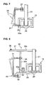
- the above-described stopper mechanism 25 comprises a base plate 29 which is fixed to a lower face of the seat rail member 19 , a stopper member 30 which is supported at an upper face of the base plate 29 , a lock plate 31 whose base end portion is supported at a lower face of the base plate 29 , and an operation lever 32 which operates the lock plate 31 .
- the stopper member 30 includes a support portion 30a which is movably (preferably rotatably or pivotably supported around a vertical axis 33 projecting from the base plate 29 ), a stand portion 30b which projects from a side end of the support portion 30a, and a substantially horizontal portion 30c which is attached to an upper end of the projecting portion 30b .
- the movement (preferably the rotation) of the stopper member 30 is normally limited by the insertion of the upper end of the lock plate 31 into an engagement hole 34 formed at the stand portion 30c of the stopper member 30.
- the assistant seat 7b is moved backward and a rear end of the slide plate 21 substantially contacts the horizontal portion 30c of the stopper member 30 as illustrated in FIG. 9, the rearward movement of the slide plate 21 is limited by the stopper member 30 of the stopper mechanism 25 .
- the position of the assistant seat 7b which is limited by the stopper mechanism 25 is set at the location slightly before the seat cushion 9 of the assistant-seat-side rear seat 8b in the normal state, so that the assistant seat 7b can be prevented from contacting knees or the like of the passenger sitting on the assistant-seat-side rear seat 8b .
- the lock plate 31 is operated in the unlock direction to release the engagement of the upper end of the lock plate 31 with the engagement hole 34 .
- the movement (preferably the rotation) of the stopper member 30 is permitted.
- the stopper member 30 moves (preferably rotates around the vertical axis 33 ) as illustrated in FIG. 10 and then the rearward movement of the slide plate 21 and the assistant seat 7b are permitted.
- a lock arm 36 to lock the seat cushion 9 preferably in its substantially horizontal use position. Also, at the horizontal portion 30c of the stopper member 30 is provided integrally or unitarily a drive lever 37 to unlock the seat cushion 9 locked by the lock arm 36 , and this lock lever 37 and the lock arm 36 are integrally or unitarily connected via a connecting member such as a wire 38 .
- the lock arm 36 is operated toward the unlock direction when the operation (preferably the rotation) of the drive lever 37 is transferred to the lock arm 36 via the wire 38 .
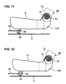
- the lock arm 36 is movably (preferably rotatably) supported on the floor panel 5 located below the seat cushion 9 of the assistant-seat-side rear seat 8b as illustrated in FIGS. 11 through 13 , while a striker 39 to be engaged by the lock arm 36 is provided at the lower face of the seat cushion 9 .
- the seat cushion 9 of the assistant-seat-side rear seat 8b is movably supported (preferably rotatably supported around a support axis 40 provided) at the support member 11B, and resiliently biased upward by a biasing means 41 which preferably comprises a torsion spring or the like which is engaged between the support axis 40 and the support member 11B.
- the lock arm 36 engages the striker 39 by a biasing means preferably comprising a torsion spring or the like which is not illustrated.
- a biasing means preferably comprising a torsion spring or the like which is not illustrated.
- the rear ends of the above-described seat rail members 19 and 20 extend rearward so as to allow the assistant seat 7b to be moved backward to the normal use position of the seat cushion 9 in the above-described stored position SP of the seat cushion 9 and the seat back 10 .
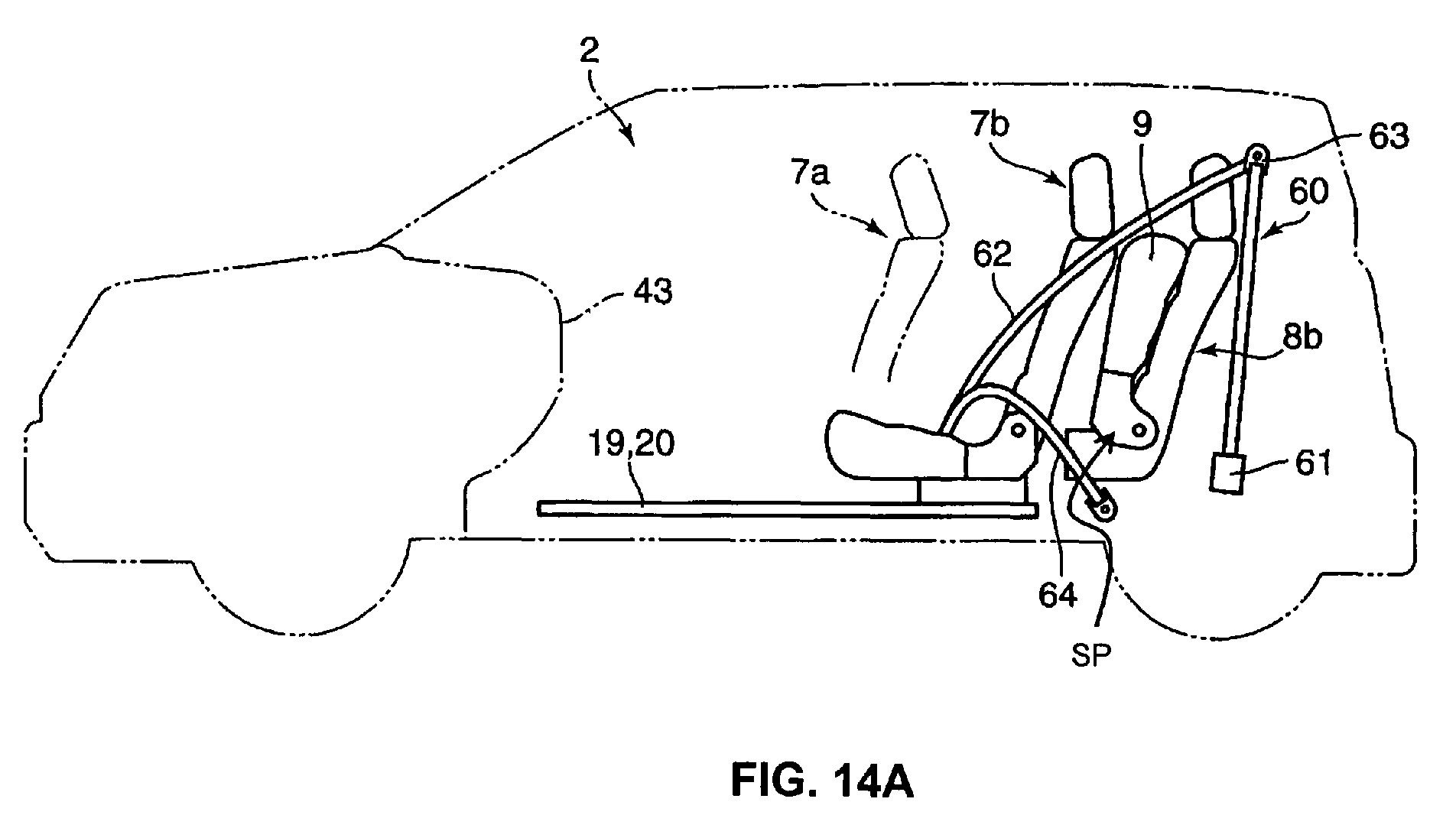
- the seat cushion 9 of the assistant seat 7b can be rotated or pivoted upward around a support axis 42 provided at the support member 11A , and the assistant seat 7b can be moved substantially forward to its stored position SP , keeping this state where both the seat cushion 9 and the seat back 10 are located in their upright positions, as illustrated in FIG. 14B.
- the front ends of the seat rail members 19 and 20 extend forward below an instrument panel 43 so as to allow the assistant seat 7b to be positioned close to the instrument panel 43 in its stored position SP .
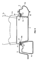
- This seat belt mechanism 60 comprises a retractor 61 which is provided at or near a lower portion behind the rear-row seat 8 , an anchor 63 which supports a shoulder belt 62 at the upper side of the vehicle, a waist belt 64 which restrains a waist portion of the passenger, and a buckle 65 which fixes or can fix a tongue (not illustrated) coupled to front ends of the shoulder and waist belts 62 and 64 to the vehicle body at the inside of the seat cushion 9 of the rear-row seat 8b .
- the seat belt mechanism 60 is configured so as to be applicable to the passenger sitting on the assistant seat 7b which has been moved back along the seat rail members 19 and 20 to a rearmost position which corresponds to the normal use position of the assistant-seat-side rear seat 8b , with the seat cushion 9 of the assistant-seat-side rear seat 8b being rotated upward to its stored position SP.
- the assistant seat 7b when the assistant seat 7b is located beside the driver seat 7a in its normal use position, the passenger sitting on the assistant-seat-side rear seat 8b can be protected by this seat belt mechanism 60. In this state, respective passengers sitting on the driver seat 7a and the assistant seat 7b are protected respectively by a driver-seat seat belt mechanism and an assistant-seat seat belt mechanism, which are not illustrated.
- the assistant seat 7b is moved toward the rear of the vehicle from the normal use position (beside the driver seat 7a ) by releasing the engagement of the assistant seat 7b by the engagement mechanism 24 , the rearward movement of the assistant seat 7b is limited by the stopper mechanism 25 at the point which is slightly before the seat cushion 9 of the rear-row seat 8b located in the normal use position.
- the rearward-movement limiting state by the stopper mechanism 25 is released and then the stopper member 30 is moved (preferably rotated) by sliding the assistant seat 7b backward, which drives the drive lever 37 to unlock the lock arm 36 .
- the engagement of the seat cushion 9 of the assistant-seat-side rear seat 8b by the lock arm 36 is released, and then the seat cushion 9 is rotated or pivoted upward by the biasing force of the biasing means 41 and moves toward or to the stored position SP .
- the assistant seat 7b is allowed to be moved rearward further along the seat rail members 19 and 20 , so that it can come to the position corresponding to the normal use position of the assistant-seat-side rear seat 8b as illustrated in FIG. 14A.
- a plurality of buckles 65 , 65 which engage at the vehicle-body side the end of seat belt from the retractor 61 of the seat belt mechanism 60 which comprises the shoulder and waist belts 62 and 64 supported by the anchor 63 . Accordingly, the front end of the seat belt may be selectively engaged with plural portions of the lower part of vehicle body.
- the passenger sitting on the assistant seat 7b in the rear position can be also properly protected by the seat belt mechanism 60 originally provided for the assistant-seat-side rear seat 8b .
- the passenger sitting on the assistant seat 7b which is moved back near the assistant-seat-side rear seat 8b which does not have its stored position SP may be protected by this seat belt mechanism 60 .
- the assistant-seat-side rear seat 8b provided behind the assistant seat 7b is configured so as to be located in the normal use position and in the stored position SP with its short longitudinal thickness or extension or dimension, and the assistant seat 7b is provided so as to be moved rearward from the normal position beside the driver seat 7a to the position substantially corresponding to or close to the normal use position of the assistant-seat-side rear seat 8b .
- the movable range of the assistant seat 7b can be enlarged effectively with a simple structure and the space in the cabin 2 can be utilized properly. And, the space which the passengers sitting on the driver seat 7a and the assistant seat 7b use can be also enlarged extremely.
- the seat cushion 9 of the assistant-seat-side rear seat 8b is rotated or pivoted upward and the longitudinal thickness or extension or dimension of the assistant-seat-side rear seat 8b is made short or reduced thereby at the area where the assistant seat 7b is located rearward.
- the rearward-movement range of the assistant seat 7b along the seat rail members 19 and 20 can be enlarged without having any complicated operations such as a removal of the assistant-seat-side rear seat 8b , so that the assistant seat 7b can be moved back to or near or close to the position corresponding to the normal use state of the assistant-seat-side rear seat 8b . Accordingly, when the assistant-seat-side rear seat 8b is not used, there can be provided the large and useful space beside the driver seat 7a and before the assistant seat 7b .
- the assistant-seat-side rear seat 8b is configured so as to make its longitudinal thickness short by rotating or pivoting the seat cushion 9 upward at the area where the assistant seat 7b is located rearward, the longitudinal thickness or dimension or extension of the assistant-seat-side rear seat 8b can be made short very easily by just rotating or pivoting the cushion 9 around or on the support axis 40 provided at the support member 11B .
- the seat cushion 9 can be automatically rotated or pivoted upward (or its movement assisted) and easily moved to the stored position SP of the assistant-seat-side rear seat 8b preferably by just releasing the engagement of the seat cushion 9 by the lock arm 36 .
- the seat belt mechanism 60 can be applicable to the passenger sitting on the assistant seat 7b by moving back the assistant seat 7b from the position beside the driver seat 7a to the position corresponding to or close to the normal use position of the assistant-seat-side rear seat 8b . Accordingly, when the assistant-seat-side rear seat 8b is not used, there can be provided the large and useful space beside the driver seat 7a and before the assistant seat 7b by moving the assistant seat 7b rearward, and the passenger sitting on the assistant seat 7b can be protected by the seat belt mechanism 60 originally provided for the rear-row seat 8 without any complicated structure such as any movements of the seat belt mechanism provided for the assistant seat 7b as well.
- the seat belt mechanism 60 which comprises the retractor 61 retracting the seat belt comprising the shoulder and waist belts 62 and 64 , the anchor 63 supporting the shoulder belt 62 from the retractor 61 at the upper side of the vehicle, the buckle 65 fixing the front ends of the shoulder and waist belts 62 and 64 to the vehicle body, is disposed so as to protect both the passenger sitting on the assistant-seat-side rear seat 8b in the normal use position and the passenger sitting on the assistant seat 7b in the rearward-moved position. Accordingly, when the assistant seat 7b is located in the normal use position beside the driver seat 7a , the seat belt mechanism 64 can protect the passenger sitting on the assistant-seat-side rear seat 8b .
- the seat belt mechanism 64 can properly protect the passenger sitting on the assistant seat 7b with the shoulder belt 62 from the retractor 61 whose both ends are supported respectively by the anchor 63 and the buckle 65 .
- the assistant-seat-side rear seat 8b is provided so as to be located in the stored position SP with the short longitudinal thickness by rotating or pivoting the seat cushion 9 upward and the assistant seat 7b is provided so as to be moved rearward along the seat rail members 19 and 20 to the position corresponding to or close to the normal use position of the assistant-seat-side rear seat 8b .
- the assistant seat 7b can be easily moved rearward to the seat belt mechanism 60 originally provided for the rear-row seat 8b without having any complicated operations such as the removal of the assistant-seat-side rear seat 8b .
- the seat belt mechanism 60 can be used for both the assistant-seat-side rear seat 8b in the normal use position and the assistant seat 7b in the rearward-moved position.
- the front-row seat 7 comprising the driver and assistant seats 7a and 7b and the rear-row seat 8b in the cabin 2 as described above
- the seat rail members 19 and 20 to support the assistant seat 7b so as to move it from the position beside the driver seat 7a to the position near the assistant-seat-side rear seat 8b .
- the movable range of the assistant seat 7b can be enlarged effectively with the simple structure and the space in the cabin 2 can be utilized properly. And, the space which the passengers sitting on the driver seat 7a and the assistant seat 7b use can be also enlarged extremely.
- the assistant seat 7b can be moved rearward to the position close to the seat cushion 9 of the assistant-seat-side rear seat 8b along the seat rail members 19 and 20 .
- the large space can be provided beside the driver seat 7a and before the assistant seat 7b , without having any complicated operations such as the removal of the assistant-seat-side rear seat 8b , and the space can be utilized properly.
- the assistant-seat-side rear seat 8b is configured so as to be located in the stored position SP with the short longitudinal thickness or dimension by rotating or pivoting the seat cushion 9 upward.
- the assistant seat 7b is configured so as to be movable to the position corresponding to the normal use state of the assistant-seat-side rear seat 8b .
- the rearward-movement range of the assistant seat 7b along the seat rail members 19 and 20 can be enlarged without having any complicated operations such as the removal of the assistant-seat-side rear seat 8b . Accordingly, when the assistant-seat-side rear seat 8b is not used, there can be provided the large and useful space beside the driver seat 7a and before the assistant seat 7b , and the utilization of the space can be effectively improved.
- the seat cushion 9 of the assistant-seat-side rear seat 8b is configured so as to be rotated or pivoted upward around the support axis 40 provided at the support member 11B and the biasing means 41 to rotate or pivot the seat cushion 9 upward is provided
- the seat cushion 9 can be preferably automatically rotated or pivoted upward and easily moved to the stored position SP of the assistant-seat-side rear seat 8b by just releasing the engagement of the seat cushion 9 by the lock arm 36 .
- the seat rail member 20 supporting the outside edge portion of the assistant seat 7b is provided on the side sill 6 as a rigidity member which extends preferably substantially in the longitudinal direction along or near the side edge portion of the vehicle body, the sufficient supporting rigidity of the seat rail member 20 can be endured, and the side sill 6 can be reinforced effectively by, for example, welding the seat rail member 20 to the side sill 6 .
- the seat rail member 20 is located in the recess portion 6c formed along the inside edge of the upper face of the inner panel 6b of the side sill 6 in the embodiment, the disposition of the seat rail member 20 can be made stable effectively, and also the seat rail member 20 can be prevented from projecting from the side sill 6 so as to improve the passenger's getting on and off.
- the seat rail member 19 supporting the inside edge portion of the assistant seat 7b is provided on or at the tunnel portion 12 extending substantially in the longitudinal direction at the central portion of the vehicle as a rigidity member like the above-described embodiment, the sufficient supporting rigidity of the seat rail member 19 can be ensured, and the tunnel portion 12 can be reinforced by the seat rail member 19 so as to improve its rigidity by fixing (preferably welding) the seat rail member 19 to the tunnel portion 12 .
- the assistant seat 7b since the rearward movement of the assistant seat 7b is limited by the stopper mechanism 25 at the location slightly before the seat cushion 9 of the assistant-seat-side rear seat 8b in the normal state, the assistant seat 7b can be prevented from contacting knees or the like of the passenger sitting on the assistant-seat-side rear seat 8b when the assistant seat 7b is moved rearward.
- the stopper member 30 is moved (preferably rotated) by sliding the assistant seat 7b rearward and at the same time the drive lever 37 is driven in the unlock direction of the lock arm 36 . Accordingly, the seat cushion 9 of the assistant-seat-side rear seat 8b can be rotated or pivoted upward to or toward its stored position SP at the proper timing by the biasing force of the biasing means 41 .
- a drive link to move the seat cushion 9 upward to or toward the stored position SP by the rearward-movement operation of the assistant seat 7b or the seat cushion 9 may be configured so as to be rotated or pivoted upward to or toward the stored position SP by a manual operation of the passenger.
- an electric drive mechanism or a drive cylinder which rotates or pivots the cushion 9 upward automatically by output signals of a detecting means which detects the rearward-movement operation of the assistant seat 7b or a switching operation by the passenger.
- the seat back 10 of the assistant-seat-side rear seat 8b may be supported by the support axis 40 so as to be rotated or folded or pivoted forward and folded on the seat cushion 9 as illustrated by a broken line in FIG. 16, and there may be provided an engagement mechanism 48 to engage a rear end portion of the seat cushion 9 at the vehicle floor and a support link 49 to rotatably support the seat cushion 9 .
- the engagement mechanism 48 comprises a lock arm 51 to be engaged by a striker 50 fixed to the lower face of the seat cushion 9 to lock the seat cushion 9 in the substantially horizontal position, and a drive lever 52 to release locking of the lock arm 51 with the striker 50 .
- the assistant-seat-side rear seat 8b can be at least partly located and stored in a storing recess 53 formed at the floor panel 5 as illustrated in FIG. 17 .
- the assistant seat 7b is allowed to be moved rearward beyond this at least partly stored assistant-seat-side rear seat 8b in the recess 53 to the position where the assistant-seat-side rear seat 8b in the stored position SP is located, the rearward-movement range of the assistant seat 7b can be further enlarged.
- the independent seats 8a and 8b of the rear-row seat 8 which can be at least partly stored separately like the above-described embodiment, there may be provided a single integrated rear seat 8 which can be stored integrally or unitarily.
- the independent rear seat 8a behind the driver seat 7a remains or can remain in the normal use position and the assistant seat 7b is moved rearward to the position corresponding to the normal use position of the assistant-seat-side rear seat 8b in the stored position SP , which is beside the independent rear seat 8a as illustrated in FIG. 18. Accordingly, plural passengers can sit side by side on the assistant seat 7b and the independent rear seat 8a , with the large space formed in front of the assistant seat 7b .
- the both seat cushions 9 , 9 of the assistant seat 7b and the independent rear seat 8a are located at substantially the substantially same level so as to create a continuous sitting face thereby, the both seat cushions 9 , 9 can be used integrally and thus the seat utility of the vehicle can be improved effectively.
- the assistant-seat-side rear seat 8b in the stored position SP may be moved rearward further than or beyond its normal use position, so that the more complete continuous sitting face can be created by the both seat cushions 9 , 9 .
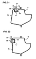
- the assistant seat 7b is located in the stored position SP with the short longitudinal thickness by rotating or pivoting the seat cushion 9 of the assistant seat 7b upward in the present embodiment, patterns of seat arrangement of the passenger seats 7 and 8 can be increased effectively. For example, as illustrated in FIG. 19, by locating both the assistant seat 7b and the assistant-seat-side rear seat 8b in their stored positions SP and by moving the assistant seat 7b rearward to the position corresponding to or near the normal use position of the assistant-seat-side rear seat 8b, an extremely large space can be formed beside the driver seat 7a .
- the large space can be formed in back of the assistant seat 7b .
- the riding of the passengers onto the rear seat 8 can be improved effectively.
- the large space can be formed beside the driver seat 7a and the independent rear seat 8a located behind the driver seat 7a .
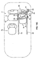
- a proper seat arrangement which would make it easy for the passenger sitting on the independent rear seat 8a behind the driver seat 7a to take care of a child in the child seat 54 can be provided, by moving the assistant seat 7b equipped with the child seat 54 to the position corresponding to or near the normal use position of the assistant-seat-side rear seat 8b . Also, the safety of the child seat 54 can be improved by locating the child seat 54 at or more towards the rear of the vehicle.
- the passengers can make access to the driver seat 7a and the assistant seat 7b from various directions, with the assistant seat 7b located in the position corresponding to the normal use position of the assistant-seat-side rear seat 8b . Accordingly, the riding of the passengers can be improved effectively.
- the slide rollers 23 , 23 rotatably provided at the lower end of the slide plate 22 may be located in a recess portion 6d formed along the upper face of the inner panel 6b as illustrated in FIG. 21, or a slide member or roller 55 (preferably rotatably) provided at the lower end of the slide plate 22 may be at least partly located in a recess portion 6e formed along the side face of the inner panel 6b as illustrated in FIG. 22.
- these recess portions 6d or 6e may be used as the seat rail members. In these cases, simpler and lighter structures can be provided.
- engagement plates 56 , 56 are provided respectively in order to prevent the slide rollers 23 and 25 from disengaging with the recess portions 6d or 6e .
- the slide roller 55 rotatably provided at the lower end of the slide plate 21 may be located in a recess portion 12b formed along the side face of the above-described tunnel portion 12 as illustrated in FIG. 23.
- the slide member or rollers 23 , 23 (preferably rotatably) provided at the lower end of the slide plate 21 may be at least partly located in a recess portion 12a formed at the inside edge portion of the upper face of the slide plate 21 as illustrated in FIG. 24.
- these recess portions 12b or 12a may be used as the seat rail members.
- the vertical movement of the slide plate 21 with its lower end being at least partly inserted in the recess portion 12b is substantially restrained by using the recess portion 12b formed along the side face of the tunnel portion 12 as the seat rail member as illustrated in FIG. 23.
- the lateral movement of the slide plate 22 with its lower end being inserted in the recess portion 6d is restrained by using the recess portion 6d formed along the upper face of the inner panel 6b as the seat rail member as illustrated in FIG. 21.
- the lateral movement of the slide plate 21 with its lower end being inserted in the recess portion 12c is substantially restrained by using the recess portion 12c formed along the upper face of the tunnel portion 12 as the seat rail member as illustrated in FIG. 24.
- the vertical movement of the slide plate 22 with its lower end being at least partly inserted in the recess portion 6e is substantially restrained by using the recess portion 6e formed along the side face of the inner panel 6b as the seat rail member as illustrated in FIG. 22 .
- the seat rail member 20 may be located on or at the upper surface of the floor panel 5 as illustrated in FIG. 25. In this case, it may be preferable to ensure a sufficient supporting rigidity of the seat rail member 20 , by providing the seat rail member 20 at a portion where the floor frame 14 extending substantially longitudinally at the lower face of the floor panel 5 as the rigidity member is disposed.
- the floor cross members 16 and 17 are provided at the lower face of the floor panel 5 because it would be difficult that the members 16 and 17 are provided at the upper face of the floor panel 5 .
- the seat rail member supporting the inner side edge portion of the assistant seat 7b i.e., the seat rail member which is made of a groove-shaped steel member and rotatably support the slide member or roller 23 provided at the lower end of the slide plate 19 , may be provided on or at the upper face of the floor panel 5 . Accordingly, the seat rail member can be provided at any portions properly.
- the assistant-seat-side rear seat 8b is configured such that the cushion seat 9 thereof is rotated or pivoted or folded upward to or toward the stored position SP , according to the rearward-movement operation of the assistant seat 7b , by the drive mechanism comprising the biasing means 41 preferably including the torsion spring (as a preferred biasing member) to resiliently bias the seat cushion 9 upward, the drive lever 37 and the wire 38 which release the engagement of the seat cushion 9 by the lock means including the lock arm 36 and the striker 39 .
- the biasing means 41 preferably including the torsion spring (as a preferred biasing member) to resiliently bias the seat cushion 9 upward, the drive lever 37 and the wire 38 which release the engagement of the seat cushion 9 by the lock means including the lock arm 36 and the striker 39 .
- the assistant seat 7b can be moved rearward to the above-described position after moving the assistant-seat-side rear seat 8b to the stored position SP just while sitting on the assistant seat 7b .
- the assistant seat 7b can be effectively prevented from contacting knees or the like of the passenger sitting on the assistant-seat-side rear seat 8b .
- the longitudinal thickness of the assistant-seat-side rear seat 8b can be made short very easily by just rotating or pivoting the cushion 9 around the support axis 40 provided at the support member 11 B.
- the independent rear seat 8a behind the driver seat 7a remains in the normal use position and the assistant seat 7b is moved rearward to the position corresponding to the normal use position of the assistant-seat-side rear seat 8b in or close to the stored position SP .
- the assistant seat 7b can be located beside the independent rear seat 8a as illustrated in Fig. 16. Accordingly, plural passengers can sit substantially side by side on the assistant seat 7b and the independent rear seat 8a, with the large space formed in front of the assistant seat 7b.
- the front-row seat (substantially a middle seat) comprising the driver seat 7a and the assistant seat 7b and the rear-row seat 8b located behind the front seat in the cabin 2
- the front seat (the middle seat) is configured so as to be moved to the position corresponding to the normal use position of the rear-row seat 8b
- the drive mechanism to move the rear seat to the stored position SP according to the rearward-movement operation of the front-row seat.
- the patterns of seat arrangement of the passenger seats can be increased effectively.
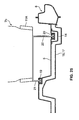
- the rear-row seat 8b may be configured so as to be moved toward or to the stored position SP by a drive link 71 which is provided so as to expand as illustrated in FIGS. 26 and 27.
- an electric drive mechanism or a drive cylinder which rotates or moves the cushion 9 of the rear-row seat 8b upward automatically to the stored position SP based on output signals of a detecting means which detects the rearward-movement operation of the assistant seat 7b .
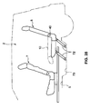
- the seat back 10 of the rear-row seat 8b may be supported by the support axis 4 0 so as to be rotated or pivoted or folded forward and folded on the seat cushion 9 as illustrated by a broken line in FIG. 28, and there may be provided a support link 72 to rotatably support the seat cushion 9 .
- the assistant-seat-side rear seat 8b may be located and stored in a storing recess 73 formed at the floor panel 5 as illustrated in FIG. 29. In this case, since the assistant seat 7b is allowed to be moved rearward further to the position where the assistant-seat-side rear seat 8b in the stored position SP is located, the rearward-movement range of the assistant seat 7b can be further enlarged.
Abstract
Description
- The present invention relates to a seat device for a vehicle, in which there are provided a front-row seat and a rear-row seat in a cabin which includes an ingress and/or egress opening at a side face, and to a vehicle provided therewith.
- Conventionally, for example, as disclosed in Patent Laid-Open Publication No. 03-235729, it is known that a middle-row seat located between a front-row seat and a rear-row seat is removed at need so as to provide a large space between the seats in a so-called one-box type of vehicle or the like, in which the rear-row (rear) seat is moved forward along a lower rail with its seat cushion being located in a sitting position, while the rear-row seat with its seat cushion being rotated upward is moved forward to form a wide load space behind the cabin.
- Also, as disclosed in US Patent No. 5,605,368, a seat slide device of an automotive vehicle is known, in which a movement range of a first-rear-row seat and a second-rear-row seat, which are supported so as to be moved in a longitudinal direction of the vehicle along a rail member, is enlarged so as to increase the seat arrangement patterns, by locating seat backs of the first-rear-row and second-rear-row seats in their upright positions for sitting, in their rearward-reclined flat positions and in their forward-folded positions, respectively.
- The above-described structure, as disclosed in the former patent publication, in which the middle-row seat located between the front-row seat and the rear-row seat is removed at need, has advantage of providing the large space between the front-row seat and the rear-row seat, while it has disadvantages that the removal of the middle-row seat would require somewhat complicated operations and a particular space for storing it, and also an operation for attaching the removed middle-row seat to the vehicle body would be necessary for using it again.
- Meanwhile, the above-described structure, as disclosed in the latter patent publication, in which the first-rear-row seat is moved rearward closely to the font end of the second-rear-row seat, has advantage that a relatively large and useful space can be provided between the foremost driver seat or assistant seat and the first-rear-row seat and this space can be used properly. However, since the rearward-movement range of the first-rear-row seat is so limited by the front end portion of the second-rear-row seat that the first-rear-row could not be moved rearward further sufficiently, it would be required that the seat arrangement patterns of passenger seats is increased.
- The present invention has been devised in view of the above-described problems, and an object of the present invention is to provide utilize a space in the cabin properly and provide a large and useful space for a passenger sitting on a front-row seat.
- This object is solved by a seat device for a vehicle according to the present invention of claim 1 and by a vehicle according to
claim 20. Preferred embodiments of the present invention are subject of the dependent claims. - According to the present invention, there is provided a seat device for a vehicle, comprising a front-row seat including a driver seat and an assistant seat, a rear-row seat provided behind the front-row seat, respective front-row and rear-row seats being provided in a cabin which includes an ingress and/or egress opening at a side face, wherein the rear-row seat is configured so as to be respectively located in a normal use position and in a stored position where a longitudinal thickness or dimension or extension thereof is made short or reduced (as compared to the normal use position), and the assistant seat is configured so as to be moved rearward from a position beside the driver seat to a position which corresponds to or near or close to the normal use position of the rear-row seat.
- Thus, there is provided a seat device for a vehicle which can utilize a space in the cabin properly, by effectively enlarging a rearward-movement range of the front-row seat including the assistant seat with a simple structure, and provide a large and useful space for a passenger sitting on the front-row seat. Accordingly, since the rearward-movement range of the assistant seat is enlarged without having any complicated operations such as a removal of the rear-row seat behind the assistant seat and the assistant seat is moved rearward to the position corresponding to or close to the normal use state of the rear-row seat, there can be provided properly the large and useful space beside the driver seat and before the assistant seat.
- According to a preferred embodiment, the rear-row seat is configured such that the longitudinal thickness or dimension or extension thereof is made short with a seat cushion of the rear-row seat being rotated or pivoted or folded upward.
- Accordingly, the longitudinal thickness or dimension or extension of the rear-row seat behind the assistant seat can be made short (as compared to the normal use position) and the rearward-movement of the assistant seat can be extremely enlarged, by just rotating the seat cushion of the rear-row seat upward.
- According to another preferred embodiment, the rear-row seat is configured so as to be further located in a lower stored position with a seat back of the rear-row seat being folded on the seat cushion of the rear-row seat, whereby the assistant seat can be moved rearward further when the rear-row seat is located in the lower stored position.
- Accordingly, the larger space can be formed beside the driver seat and before the assistant seat, by moving the assistant seat rearward when the rear-row seat is located in the lower stored position with its seat back being folded on its seat cushion.
- According to another preferred embodiment, there are provided a plurality of independent rear seats, and the independent rear seats are configured so as to be located in stored positions thereof separately.
- Accordingly, the independent rear seat behind the driver seat remains in the normal use position, the assistant seat in the stored position is moved rearward to the position corresponding to or close to the normal use position of the independent rear seat in the stored position, and the assistant seat is located substantially beside the independent rear seat. Thus, plural passengers can sit substantially side by side on the assistant seat and the independent rear seat, with the large space formed in front of the assistant seat.
- According to another preferred embodiment, a substantially continuous sitting face is formed by a seat cushion of the assistant seat and a seat cushion of the independent rear seat behind the driver seat when another independent rear seat behind the assistant seat is located in the stored position and the assistant seat is moved rearward, whereby the seat cushion of the assistant seat and the seat cushion of the independent rear seat can be located close to each other, preferably at substantially the same level (in the longitudinal direction and/or the vertical direction).
- Accordingly, since the both seat cushions of the assistant seat and the independent rear seat behind the driver seat are used integrally so as to create the substantially continuous sitting face thereby, the seat utility of the vehicle can be improved effectively.
- According to another preferred embodiment, the assistant seat is configured so as to be located in a stored position where a longitudinal thickness or dimension or extension thereof is made short with a seat cushion of the assistant seat being rotated or pivoted or folded upward.
- Accordingly, since the longitudinal thickness or dimension or extension of the assistant seat is made short by rotating or pivoting or folding the seat cushion of the assistant seat upward, patterns of seat arrangement of the passenger seats can be increased effectively.
- According to another preferred embodiment, the assistant seat located in the stored position is configured so as to be moved forward toward or closely to an instrument panel.
- Accordingly, there can be provided a large space beside the driver seat and in back of the assistant seat, by moving the assistant seat in the stored position forward toward or closely to the instrument panel.
- According to another preferred embodiment, a child seat is available or provided on the assistant seat.
- Accordingly, there can be provided a proper seat arrangement which would make it easy for the passenger sitting on the independent rear seat behind the driver seat to take care of a child in the child seat, by moving the assistant seat equipped with the child seat to the position corresponding to or close to the normal use position of the independent rear seat behind the assistant seat. Also, the safety of the child seat can be improved by locating the child seat at the rear of the vehicle.
- According to another preferred embodiment, there is provided a seat belt mechanism which is configured so as to be (selectively) applicable to passengers sitting on the rear-row seat and the assistant seat located in the rearward-moved position.
- Accordingly, since the single seat belt mechanism protects or can be used for both passengers sitting on the rear-row seat in the normal use position and the assistant seat located in the rearward-movement position, the protection of passengers can be properly and easily attained.
- According to another preferred embodiment, the belt mechanism comprises a retractor which retracts a seat belt, an anchor which supports the seat belt from the retractor at an upper side of the vehicle, and a buckle which fixes a front end of the seat belt to a vehicle body, and the seat belt mechanism is located so as to protect the passengers sitting on the rear-row seat and the assistant seat located in the rearward-moved position.
- Accordingly, when the assistant seat is located beside the driver seat in its normal use position, the passenger sitting on the rear-row seat behind the assistant seat can be protected by the seat belt mechanism in which the seat belt from the retractor is supported by the anchor provided at the upper side of the vehicle and the front end of the seat belt is fixed to the vehicle body by the buckle. Also, when the assistant seat is moved rearward closely to the rear-row seat, the passenger sitting on the assistant seat can be also protected by the same seat belt mechanism.
- According to another preferred embodiment, there is provided a seat rail member which supports the assistant seat so as to move the assistant seat rearward from the position beside the driver seat to the position which corresponds to or is close or near to the normal use position of the rear-row seat.
- Accordingly, since the assistant seat is moved rearward closely to the rear-row seat along the seat rail member without having any complicated operations such as the removal of the rear-row seat, there can be provided the large and useful space effectively beside the driver seat and before the assistant seat.
- According to another preferred embodiment, the seat rail member includes a seat rail member to support an outside edge portion of the assistant seat, and the seat rail member supporting the outside edge portion of the assistant seat is provided at a side sill which extends substantially in a longitudinal direction of the vehicle at a side portion of the vehicle.
- Accordingly, since the seat rail member supporting the outside edge portion of the assistant seat is provided at the side sill as the rigidity member which extends in the longitudinal direction at the side portion of the vehicle, the sufficient supporting rigidity of the seat rail member can be ensured, and the side sill can be reinforced effectively by, for example, welding the seat rail member to the side sill.
- According to another preferred embodiment, the seat rail member supporting the outside edge portion of the assistant seat is at least partly located in a recess portion which is formed at an inner panel of the side sill.
- Accordingly, since the seat rail member is located in the recess portion formed at the inner panel of the side sill, the disposition of the seat rail member can be made stable effectively, and also the seat rail member can be prevented from projecting from the side sill so as to improve the passenger's getting on and off.
- According to another preferred embodiment, the recess portion which is formed at the inner panel of the side sill is used as the seat rail member supporting the outside edge portion of the assistant seat.
- Accordingly, since the recess portion formed at the inner panel of the side sill is used as the seat rail member supporting the outside edge portion of the assistant seat, the structure can be made simpler and lighter.
- According to another preferred embodiment, the seat rail member includes a seat rail member to be provided at a portion of a floor panel, at which a floor frame which extends substantially in a longitudinal direction of the vehicle is provided.
- Accordingly, since there is provided the seat rail member to be provided at the portion of the floor panel at which the floor frame extending substantially in the longitudinal direction is provided, the sufficient supporting rigidity of the seat rail member can be ensured.
- According to another preferred embodiment, there is provided a floor cross member which extends substantially in a vehicle width direction (i.e. a direction at an angle different from 0° or 180°, preferably substantially normal to the longitudinal direction) is provided at or on a lower face of the floor panel.
- Accordingly, since the floor cross member is provided at the lower face of the floor panel, the rigidity of the floor panel which even supports the seat rail member thereon can be increased effectively.
- According to another preferred embodiment, the seat rail member includes a seat rail member to support an inside edge portion of the assistant seat, and the seat rail member supporting the inside edge portion of the assistant seat is provided at or on a tunnel portion which extends substantially in the longitudinal direction of the vehicle at a central portion of the vehicle.
- Accordingly, since the seat rail member supporting the inside edge portion of the assistant seat is provided at the tunnel portion as the rigidity member which extends substantially in the longitudinal direction at the central portion of the vehicle, the sufficient supporting rigidity of the seat rail member can be ensured, and the tunnel portion can be reinforced by the seat rail member so as to improve its rigidity by welding the seat rail member to the tunnel portion.
- According to another preferred embodiment, there is provided a drive mechanism which moves the rear-row seat to the stored position along with a rearward-movement operation of the assistant seat.
- Accordingly, the rear-row seat is located in the stored position with the short longitudinal thickness by moving rearward the assistant seat and the rearward-movement range of the assistant seat is enlarged without having any complicated operations such as the removal of the rear-row seat behind the assistant seat. Also, the assistant seat is moved rearward to the position corresponding to the normal use position of the rear-row seat. Thus, there can be provided properly the large and useful space beside the driver seat and before the assistant seat.
- According to another preferred embodiment, there is provided a stopper mechanism which limits the rearward movement of the assistant seat at a point which is close to a seat cushion of the rear-row seat located in the normal use position.
- Accordingly, since the rearward movement of the assistant seat is limited by the stopper mechanism at the point which is close to the seat cushion of the rear-row seat located in the normal use position, the assistant seat can be prevented from contacting knees or the like of the passenger sitting on the rear-row seat.
- Other features, aspects, and advantages of the present invention will become apparent from the following description which refers to the accompanying drawings.
- FIG. 1 is a side view illustrating a seat device for a vehicle according to an embodiment of the present invention.
- FIG. 2 is a perspective view illustrating the seat device for a vehicle according to the present embodiment.
- FIG. 3 is a plan view illustrating a specific structure of a floor panel.
- FIG. 4 is a perspective view illustrating the specific structure of the floor panel.
- FIG. 5 is a sectional elevation view illustrating a disposition state of a seat rail member.
- FIG. 6 is a perspective view illustrating a specific structure of an engagement mechanism and a stopper mechanism for an assistant seat.
- FIG. 7 is an elevation view illustrating the specific structure of the engagement mechanism.
- FIG. 8 is an elevation view illustrating the specific structure of the stopper mechanism.
- FIG. 9 is a plan view illustrating an engagement state of a slide plate.
- FIG. 10 is a plan view illustrating an engagement-release state of the slide plate.
- FIG. 11 is a side view illustrating an engagement state of a seat cushion of an assistant-seat-side rear seat.
- FIG. 12 is a side view illustrating an engagement-release state of the seat cushion of the assistant-seat-side rear seat.
- FIG. 13 is a side view illustrating a state in which the seat cushion of the assistant-seat-side rear seat is rotated upward.
- FIG. 14A is a side view illustrating a state in which the assistant seat is moved rearward.
- FIG. 14B is a side view illustrating a state in which the assistant seat is moved forward.
- FIG. 15A is a plan view illustrating the state in which the assistant seat is moved forward.
- FIG. 15B is a side view illustrating the seat device for a vehicle with a seat belt mechanism of the present embodiment.
- FIG. 15C is a plan view illustrating a use state of the seat belt mechanism.
- FIG. 16 is a side view illustrating another embodiment of the present invention.
- FIG. 17 is a side view illustrating a state in which the assistant-seat-side rear seat is stored.
- FIG. 18 is a plan view illustrating a disposition state of a child seat.
- FIG. 19 is a plan view illustrating the state in which the assistant seat is moved rearward.
- FIG. 20 is a plan view illustrating a state in which the assistant-seat-side rear seat is stored and the assistant seat is moved forward.
- FIG. 21 is a sectional elevation view illustrating a modified disposition structure of the seat rail member.
- FIG. 22 is a sectional elevation view illustrating further another modified disposition structure of the seat rail member.
- FIG. 23 is a sectional elevation view illustrating further another modified disposition structure of the seat rail member.
- FIG. 24 is a sectional elevation view illustrating further another modified disposition structure of the seat rail member.
- FIG. 25 is a sectional elevation view illustrating further another modified disposition structure of the seat rail member.
- FIG. 26 is a side view illustrating further anther embodiment of the present invention.
- FIG. 27 is a side view illustrating a state in which a front-row seat is moved rearward.
- FIG. 28 is a side view illustrating further another embodiment of the present invention.
- FIG. 29 is a side view illustrating a state in which a rear-row seat is stored at a lower portion of the vehicle.
-
- Hereinafter, preferred embodiments of the present invention will be described referring to the accompanying drawings. It should be understood that even though embodiments are separately described, single features thereof may be combined to additional embodiments.
- FIG. 1 through 5 illustrate schematic views of a vehicle including a seat device for a vehicle according to a preferred embodiment of the present invention. The vehicle illustrated preferably is a so-called minivan type of vehicle, in which a cabin or
passenger compartment 2 including a plurality of ingress andegress openings wheel axle 3 and a rear-wheel axle 4. There is provided afloor panel 5 between right andleft side sills cabin 2, and one or more, preferably a plurality ofpassenger seats floor panel 5. Namely, a front-row seat 7 preferably comprising adriver seat 7a and anassistant seat 7b is disposed at a front portion of thefloor panel 5, and a rear-row seat 8 preferably comprising a pair ofindependent seats row seat 7. - Each of the
passenger seats seat cushion 9 and a seat back 10. At least theassistant seat 7b and the rear seat (hereinafter, referred to as "assistant-seat-side rear seat") 8b, which is located just behind theassistant seat 7b, includesupport members respective seat cushions seat cushions assistant seat 7b and the assistant-seat-siderear seat 8b are configured so as to be located in their use positions, where they are disposed substantially horizontally as illustrated in FIG. 1, and in their stored or folded positions SP, where they are rotated or pivoted upward and folded with a short longitudinal thickness or extension or dimension as illustrated in FIG. 2. - At an intermediate portion (preferably substantially the central portion) of the
floor panel 5, as illustrated in FIGS. 3 and 4, is provided atunnel portion 12, which projects substantially upward so as to extend substantially in the longitudinal direction of the vehicle and whose both ends preferably are fixed to inside faces of the above-describedside sills floor panel 5 is attached one or more, preferably a pair of floor frames 14, 14 extending preferably substantially in the longitudinal direction at right and left sides, whose front ends are connected integrally or unitarily with front side frames 15, 15 respectively which are at least partly disposed in an engine room located at the front of vehicle. - A pair of front and rear
floor cross members floor panel 5 so as to interconnect thetunnel portion 12 and theside sills fuel tank 18 is at least partly disposed below thetunnel portion 12, preferably substantially extending in the longitudinal direction (see FIG. 5). The upper face of thetunnel portion 12 includes arecess portion 12a at or near one side edge thereof (the one edge at or toward a side ofassistant seat 7b), in which aseat rail member 19 to support an inside edge portion of theassistant seat 7b is disposed. - Each of the
side sills outer panel 6a and aninner panel 6b, which are connected with each other via upper and lower flanges. Also, the upper face of theinner panel 6b includes arecess portion 6c at an inside edge thereof, in which aseat rail member 20 to support an outside edge portion of theassistant seat 7b is at least partly disposed. - The above-described
seat rail members slide plates rail members rollers slide plates seat rail members slide plates assistant seat 7b are provided so as to slide substantially in the longitudinal direction of the vehicle. - The
slide plate 21 which is located at the inside of the vehicle has anengagement mechanism 24 to fix theassistant seat 7b to any specified (predetermined or predeterminable) longitudinal positions as illustrated in FIGS. 6 through 10. Also, theseat rail member 19 supporting theslide plate 21 at the inside of the vehicle has astopper mechanism 25 to limit a longitudinal movement of theassistant seat 7b at any specified positions. - The above-described
engagement mechanism 24 comprises alock plate 26 which is movable (preferably rotatably or pivotably) supported at theslide plate 21, and anoperation lever 27 which operates thelock plate 26. At the lower end of thelock plate 26 is provided anengagement projection 26a which projects toward theseat rail member 19, and at the side face of theseat rail member 19 are provided some slots or engagement recesses 28 with specified (predetermined or predeterminable) intervals. The longitudinal movement of theslide plate 21 and theassistant seat 7b are limited by engaging theengagement projection 26a at thelock plate 26 with theslots 28 at theseat rail member 19. Meanwhile, the longitudinal movement of theslide plate 21 and theassistant seat 7b are permitted by releasing the engagement of theengagement projection 26a with theslots 28 with the operation of thelock plate 26 toward an unlock direction by theoperation lever 27. - The above-described
stopper mechanism 25 comprises abase plate 29 which is fixed to a lower face of theseat rail member 19, astopper member 30 which is supported at an upper face of thebase plate 29, alock plate 31 whose base end portion is supported at a lower face of thebase plate 29, and anoperation lever 32 which operates thelock plate 31. Thestopper member 30 includes asupport portion 30a which is movably (preferably rotatably or pivotably supported around avertical axis 33 projecting from the base plate 29), astand portion 30b which projects from a side end of thesupport portion 30a, and a substantiallyhorizontal portion 30c which is attached to an upper end of the projectingportion 30b. - Herein, the movement (preferably the rotation) of the
stopper member 30 is normally limited by the insertion of the upper end of thelock plate 31 into anengagement hole 34 formed at thestand portion 30c of thestopper member 30. In this state, when theassistant seat 7b is moved backward and a rear end of theslide plate 21 substantially contacts thehorizontal portion 30c of thestopper member 30 as illustrated in FIG. 9, the rearward movement of theslide plate 21 is limited by thestopper member 30 of thestopper mechanism 25. The position of theassistant seat 7b which is limited by thestopper mechanism 25 is set at the location slightly before theseat cushion 9 of the assistant-seat-siderear seat 8b in the normal state, so that theassistant seat 7b can be prevented from contacting knees or the like of the passenger sitting on the assistant-seat-siderear seat 8b. - At the point the
assistant seat 7b comes to the above-described limit position, thelock plate 31 is operated in the unlock direction to release the engagement of the upper end of thelock plate 31 with theengagement hole 34. Thus, the movement (preferably the rotation) of thestopper member 30 is permitted. As a result, when the limit of the rearward movement of theslide plate 21 by thestopper member 30 is released and then theassistant seat 7b is pushed backward, thestopper member 30 moves (preferably rotates around the vertical axis 33) as illustrated in FIG. 10 and then the rearward movement of theslide plate 21 and theassistant seat 7b are permitted. - At the assistant-seat-side
rear seat 8b behind theassistant seat 7b is provided alock arm 36 to lock theseat cushion 9 preferably in its substantially horizontal use position. Also, at thehorizontal portion 30c of thestopper member 30 is provided integrally or unitarily adrive lever 37 to unlock theseat cushion 9 locked by thelock arm 36, and thislock lever 37 and thelock arm 36 are integrally or unitarily connected via a connecting member such as awire 38. Thelock arm 36 is operated toward the unlock direction when the operation (preferably the rotation) of thedrive lever 37 is transferred to thelock arm 36 via thewire 38. - Namely, the
lock arm 36 is movably (preferably rotatably) supported on thefloor panel 5 located below theseat cushion 9 of the assistant-seat-siderear seat 8b as illustrated in FIGS. 11 through 13, while astriker 39 to be engaged by thelock arm 36 is provided at the lower face of theseat cushion 9. Also, theseat cushion 9 of the assistant-seat-siderear seat 8b is movably supported (preferably rotatably supported around asupport axis 40 provided) at thesupport member 11B, and resiliently biased upward by a biasing means 41 which preferably comprises a torsion spring or the like which is engaged between thesupport axis 40 and thesupport member 11B. - And, in the normal state, the
lock arm 36 engages thestriker 39 by a biasing means preferably comprising a torsion spring or the like which is not illustrated. Thus, as illustrated in FIG. 11, theseat cushion 9 of the assistant-seat-siderear seat 8b is locked in the substantially horizontal use position against the biasing force of the biasing means 41. - When the
stopper member 30 and thedrive lever 37 are operated (preferably rotated around the vertical axis 33) by pushing theassistant seat 7b backward as illustrated in FIG. 10, thelock arm 36 is driven toward the releasing direction of the engagement with thestriker 39 via the above-described connecting member orwire 38. Thus, the engagement of thelock arm 36 with theseat cushion 9 is released as illustrated in FIG. 12. As a result, theseat cushion 9 is rotated or pivoted upward around thesupport axis 40 by the biasing force of the biasing means 41 as illustrated in FIGS. 13 and 14A, and theseat cushion 9 and the seat back 10 are both located in the substantially upright positions, i.e., in the stored positions SP where the assistant-seat-siderear seat 8b has a short longitudinal thickness or extension. - Herein, the rear ends of the above-described
seat rail members assistant seat 7b to be moved backward to the normal use position of theseat cushion 9 in the above-described stored position SP of theseat cushion 9 and the seat back 10. - Also, the
seat cushion 9 of theassistant seat 7b can be rotated or pivoted upward around asupport axis 42 provided at thesupport member 11A, and theassistant seat 7b can be moved substantially forward to its stored position SP, keeping this state where both theseat cushion 9 and the seat back 10 are located in their upright positions, as illustrated in FIG. 14B. Herein, the front ends of theseat rail members instrument panel 43 so as to allow theassistant seat 7b to be positioned close to theinstrument panel 43 in its stored position SP. - Further, as illustrated in FIGS. 14A, 14B, 15A and 15B, at the rear side of the
cabin 2 is provided a three-point-type ofseat belt mechanism 60 to protect the passenger on the rear-row seat 8b. Thisseat belt mechanism 60 comprises aretractor 61 which is provided at or near a lower portion behind the rear-row seat 8, ananchor 63 which supports ashoulder belt 62 at the upper side of the vehicle, awaist belt 64 which restrains a waist portion of the passenger, and abuckle 65 which fixes or can fix a tongue (not illustrated) coupled to front ends of the shoulder andwaist belts seat cushion 9 of the rear-row seat 8b. As illustrated in 14A, theseat belt mechanism 60 is configured so as to be applicable to the passenger sitting on theassistant seat 7b which has been moved back along theseat rail members rear seat 8b, with theseat cushion 9 of the assistant-seat-siderear seat 8b being rotated upward to its stored position SP. - Also, as illustrated in FIG. 15B, when the
assistant seat 7b is located beside thedriver seat 7a in its normal use position, the passenger sitting on the assistant-seat-siderear seat 8b can be protected by thisseat belt mechanism 60. In this state, respective passengers sitting on thedriver seat 7a and theassistant seat 7b are protected respectively by a driver-seat seat belt mechanism and an assistant-seat seat belt mechanism, which are not illustrated. - Then, when the
assistant seat 7b is moved toward the rear of the vehicle from the normal use position (beside thedriver seat 7a) by releasing the engagement of theassistant seat 7b by theengagement mechanism 24, the rearward movement of theassistant seat 7b is limited by thestopper mechanism 25 at the point which is slightly before theseat cushion 9 of the rear-row seat 8b located in the normal use position. - In order to allow the
assistant seat 7b to be moved rearward further from this point, the rearward-movement limiting state by thestopper mechanism 25 is released and then thestopper member 30 is moved (preferably rotated) by sliding theassistant seat 7b backward, which drives thedrive lever 37 to unlock thelock arm 36. As a result, the engagement of theseat cushion 9 of the assistant-seat-siderear seat 8b by thelock arm 36 is released, and then theseat cushion 9 is rotated or pivoted upward by the biasing force of the biasing means 41 and moves toward or to the stored position SP. Thus, theassistant seat 7b is allowed to be moved rearward further along theseat rail members rear seat 8b as illustrated in FIG. 14A. - Further, as illustrated in FIG. 15C, there may be provided a plurality of
buckles retractor 61 of theseat belt mechanism 60 which comprises the shoulder andwaist belts anchor 63. Accordingly, the front end of the seat belt may be selectively engaged with plural portions of the lower part of vehicle body. Thus, the passenger sitting on theassistant seat 7b in the rear position can be also properly protected by theseat belt mechanism 60 originally provided for the assistant-seat-siderear seat 8b. Also, the passenger sitting on theassistant seat 7b which is moved back near the assistant-seat-siderear seat 8b which does not have its stored position SP may be protected by thisseat belt mechanism 60. - As described above, in the vehicle in which there are provided the front-
row seat 7 comprising the driver andassistant seats row seat 8b in thecabin 2 which includes the one or more ingress andegress openings rear seat 8b provided behind theassistant seat 7b is configured so as to be located in the normal use position and in the stored position SP with its short longitudinal thickness or extension or dimension, and theassistant seat 7b is provided so as to be moved rearward from the normal position beside thedriver seat 7a to the position substantially corresponding to or close to the normal use position of the assistant-seat-siderear seat 8b. Accordingly, the movable range of theassistant seat 7b can be enlarged effectively with a simple structure and the space in thecabin 2 can be utilized properly. And, the space which the passengers sitting on thedriver seat 7a and theassistant seat 7b use can be also enlarged extremely. - Namely, the
seat cushion 9 of the assistant-seat-siderear seat 8b is rotated or pivoted upward and the longitudinal thickness or extension or dimension of the assistant-seat-siderear seat 8b is made short or reduced thereby at the area where theassistant seat 7b is located rearward. Thus, the rearward-movement range of theassistant seat 7b along theseat rail members rear seat 8b, so that theassistant seat 7b can be moved back to or near or close to the position corresponding to the normal use state of the assistant-seat-siderear seat 8b. Accordingly, when the assistant-seat-siderear seat 8b is not used, there can be provided the large and useful space beside thedriver seat 7a and before theassistant seat 7b. - Also, since the assistant-seat-side
rear seat 8b is configured so as to make its longitudinal thickness short by rotating or pivoting theseat cushion 9 upward at the area where theassistant seat 7b is located rearward, the longitudinal thickness or dimension or extension of the assistant-seat-siderear seat 8b can be made short very easily by just rotating or pivoting thecushion 9 around or on thesupport axis 40 provided at thesupport member 11B. Particularly, in the case where the biasing means 41 to rotate or pivot theseat cushion 9 upward around thesupport axis 40 is provided like the above-described embodiment, theseat cushion 9 can be automatically rotated or pivoted upward (or its movement assisted) and easily moved to the stored position SP of the assistant-seat-siderear seat 8b preferably by just releasing the engagement of theseat cushion 9 by thelock arm 36. - Further, the
seat belt mechanism 60 can be applicable to the passenger sitting on theassistant seat 7b by moving back theassistant seat 7b from the position beside thedriver seat 7a to the position corresponding to or close to the normal use position of the assistant-seat-siderear seat 8b. Accordingly, when the assistant-seat-siderear seat 8b is not used, there can be provided the large and useful space beside thedriver seat 7a and before theassistant seat 7b by moving theassistant seat 7b rearward, and the passenger sitting on theassistant seat 7b can be protected by theseat belt mechanism 60 originally provided for the rear-row seat 8 without any complicated structure such as any movements of the seat belt mechanism provided for theassistant seat 7b as well. - Namely, in the above-described embodiment, the
seat belt mechanism 60, which comprises theretractor 61 retracting the seat belt comprising the shoulder andwaist belts anchor 63 supporting theshoulder belt 62 from theretractor 61 at the upper side of the vehicle, thebuckle 65 fixing the front ends of the shoulder andwaist belts rear seat 8b in the normal use position and the passenger sitting on theassistant seat 7b in the rearward-moved position. Accordingly, when theassistant seat 7b is located in the normal use position beside thedriver seat 7a, theseat belt mechanism 64 can protect the passenger sitting on the assistant-seat-siderear seat 8b. Meanwhile, when theassistant seat 7b is moved rearward to the position corresponding to or near the normal use position of the assistant-seat-siderear seat 8b, theseat belt mechanism 64 can properly protect the passenger sitting on theassistant seat 7b with theshoulder belt 62 from theretractor 61 whose both ends are supported respectively by theanchor 63 and thebuckle 65. - Particularly, in the above-described embodiment, the assistant-seat-side
rear seat 8b is provided so as to be located in the stored position SP with the short longitudinal thickness by rotating or pivoting theseat cushion 9 upward and theassistant seat 7b is provided so as to be moved rearward along theseat rail members rear seat 8b. Accordingly, theassistant seat 7b can be easily moved rearward to theseat belt mechanism 60 originally provided for the rear-row seat 8b without having any complicated operations such as the removal of the assistant-seat-siderear seat 8b. Also, theseat belt mechanism 60 can be used for both the assistant-seat-siderear seat 8b in the normal use position and theassistant seat 7b in the rearward-moved position. Thus, both the space utilization and the passenger protection can be attained with the simple structure. - Further, in the vehicle in which there are provided the front-
row seat 7 comprising the driver andassistant seats row seat 8b in thecabin 2 as described above, there are provided theseat rail members assistant seat 7b so as to move it from the position beside thedriver seat 7a to the position near the assistant-seat-siderear seat 8b. Accordingly, the movable range of theassistant seat 7b can be enlarged effectively with the simple structure and the space in thecabin 2 can be utilized properly. And, the space which the passengers sitting on thedriver seat 7a and theassistant seat 7b use can be also enlarged extremely. - Namely, when the assistant-seat-side
rear seat 8b is not used, theassistant seat 7b can be moved rearward to the position close to theseat cushion 9 of the assistant-seat-siderear seat 8b along theseat rail members driver seat 7a and before theassistant seat 7b, without having any complicated operations such as the removal of the assistant-seat-siderear seat 8b, and the space can be utilized properly. - Particularly, in the above-described embodiment, the assistant-seat-side
rear seat 8b is configured so as to be located in the stored position SP with the short longitudinal thickness or dimension by rotating or pivoting theseat cushion 9 upward. And, theassistant seat 7b is configured so as to be movable to the position corresponding to the normal use state of the assistant-seat-siderear seat 8b. Thus, the rearward-movement range of theassistant seat 7b along theseat rail members rear seat 8b. Accordingly, when the assistant-seat-siderear seat 8b is not used, there can be provided the large and useful space beside thedriver seat 7a and before theassistant seat 7b, and the utilization of the space can be effectively improved. - Also, in the case like the above-described embodiment, where the
seat cushion 9 of the assistant-seat-siderear seat 8b is configured so as to be rotated or pivoted upward around thesupport axis 40 provided at thesupport member 11B and the biasing means 41 to rotate or pivot theseat cushion 9 upward is provided, theseat cushion 9 can be preferably automatically rotated or pivoted upward and easily moved to the stored position SP of the assistant-seat-siderear seat 8b by just releasing the engagement of theseat cushion 9 by thelock arm 36. - In the above-described embodiment, since the
seat rail member 20 supporting the outside edge portion of theassistant seat 7b is provided on theside sill 6 as a rigidity member which extends preferably substantially in the longitudinal direction along or near the side edge portion of the vehicle body, the sufficient supporting rigidity of theseat rail member 20 can be endured, and theside sill 6 can be reinforced effectively by, for example, welding theseat rail member 20 to theside sill 6. - Particularly, since the
seat rail member 20 is located in therecess portion 6c formed along the inside edge of the upper face of theinner panel 6b of theside sill 6 in the embodiment, the disposition of theseat rail member 20 can be made stable effectively, and also theseat rail member 20 can be prevented from projecting from theside sill 6 so as to improve the passenger's getting on and off. - Also, in the case where the
seat rail member 19 supporting the inside edge portion of theassistant seat 7b is provided on or at thetunnel portion 12 extending substantially in the longitudinal direction at the central portion of the vehicle as a rigidity member like the above-described embodiment, the sufficient supporting rigidity of theseat rail member 19 can be ensured, and thetunnel portion 12 can be reinforced by theseat rail member 19 so as to improve its rigidity by fixing (preferably welding) theseat rail member 19 to thetunnel portion 12. - In the above-described embodiment, since the rearward movement of the
assistant seat 7b is limited by thestopper mechanism 25 at the location slightly before theseat cushion 9 of the assistant-seat-siderear seat 8b in the normal state, theassistant seat 7b can be prevented from contacting knees or the like of the passenger sitting on the assistant-seat-siderear seat 8b when theassistant seat 7b is moved rearward. - And, after the above-described rearward-movement limitation is released by operating the
operation lever 32 at thestopper mechanism 25, thestopper member 30 is moved (preferably rotated) by sliding theassistant seat 7b rearward and at the same time thedrive lever 37 is driven in the unlock direction of thelock arm 36. Accordingly, theseat cushion 9 of the assistant-seat-siderear seat 8b can be rotated or pivoted upward to or toward its stored position SP at the proper timing by the biasing force of the biasing means 41. - Herein, instead of the above-described structure in which the
seat cushion 9 of the assistant-seat-siderear seat 8b can be rotated or pivoted or folded upward toward or to its stored position SP by the biasing force of the biasing means 41, there may be provided a drive link to move theseat cushion 9 upward to or toward the stored position SP by the rearward-movement operation of theassistant seat 7b or theseat cushion 9 may be configured so as to be rotated or pivoted upward to or toward the stored position SP by a manual operation of the passenger. Further, there may be provided an electric drive mechanism or a drive cylinder which rotates or pivots thecushion 9 upward automatically by output signals of a detecting means which detects the rearward-movement operation of theassistant seat 7b or a switching operation by the passenger. - Also, the seat back 10 of the assistant-seat-side
rear seat 8b may be supported by thesupport axis 40 so as to be rotated or folded or pivoted forward and folded on theseat cushion 9 as illustrated by a broken line in FIG. 16, and there may be provided anengagement mechanism 48 to engage a rear end portion of theseat cushion 9 at the vehicle floor and asupport link 49 to rotatably support theseat cushion 9. Theengagement mechanism 48 comprises alock arm 51 to be engaged by astriker 50 fixed to the lower face of theseat cushion 9 to lock theseat cushion 9 in the substantially horizontal position, and adrive lever 52 to release locking of thelock arm 51 with thestriker 50. - Herein, when the engagement of the
seat cushion 9 by thelock arm 51 is released by the operation of thedrive lever 52 and the assistant-seat-siderear seat 8b with the seat back 10 folded on or toward theseat cushion 9 is rotated forward by thesupport link 49, the assistant-seat-siderear seat 8b can be at least partly located and stored in a storingrecess 53 formed at thefloor panel 5 as illustrated in FIG. 17. In this case, since theassistant seat 7b is allowed to be moved rearward beyond this at least partly stored assistant-seat-siderear seat 8b in therecess 53 to the position where the assistant-seat-siderear seat 8b in the stored position SP is located, the rearward-movement range of theassistant seat 7b can be further enlarged. - Also, instead of the
independent seats row seat 8 which can be at least partly stored separately like the above-described embodiment, there may be provided a single integratedrear seat 8 which can be stored integrally or unitarily. - However, in the case where the
independent seats rear seat 8a behind thedriver seat 7a remains or can remain in the normal use position and theassistant seat 7b is moved rearward to the position corresponding to the normal use position of the assistant-seat-siderear seat 8b in the stored position SP, which is beside the independentrear seat 8a as illustrated in FIG. 18. Accordingly, plural passengers can sit side by side on theassistant seat 7b and the independentrear seat 8a, with the large space formed in front of theassistant seat 7b. - Particularly, in the case where, by locating the assistant-seat-side
rear seat 8b in the stored position SP and by moving theassistant seat 7b rearward, the bothseat cushions assistant seat 7b and the independentrear seat 8a are located at substantially the substantially same level so as to create a continuous sitting face thereby, the bothseat cushions rear seat 8b in the stored position SP may be moved rearward further than or beyond its normal use position, so that the more complete continuous sitting face can be created by the bothseat cushions - Also, since the
assistant seat 7b is located in the stored position SP with the short longitudinal thickness by rotating or pivoting theseat cushion 9 of theassistant seat 7b upward in the present embodiment, patterns of seat arrangement of thepassenger seats assistant seat 7b and the assistant-seat-siderear seat 8b in their stored positions SP and by moving theassistant seat 7b rearward to the position corresponding to or near the normal use position of the assistant-seat-siderear seat 8b, an extremely large space can be formed beside thedriver seat 7a. - Particularly, in the case where the
assistant seat 7b is moved forward closely to theinstrument panel 43 with theseat cushion 9 in its stored position SP along theseat rail members assistant seat 7b. Thus, the riding of the passengers onto therear seat 8 can be improved effectively. Also, as illustrated in FIG. 20, by moving theassistant seat 7b forward closely to theinstrument panel 43 with theseat cushion 9 in its stored position SP and by locating the assistant-seat-siderear seat 8b in the stored position SP, the large space can be formed beside thedriver seat 7a and the independentrear seat 8a located behind thedriver seat 7a. - Also, in the case where a
child seat 54 is available or provided on theassistant seat 7b as illustrated by a broken line in FIG. 18, a proper seat arrangement which would make it easy for the passenger sitting on the independentrear seat 8a behind thedriver seat 7a to take care of a child in thechild seat 54 can be provided, by moving theassistant seat 7b equipped with thechild seat 54 to the position corresponding to or near the normal use position of the assistant-seat-siderear seat 8b. Also, the safety of thechild seat 54 can be improved by locating thechild seat 54 at or more towards the rear of the vehicle. - Also, in the vehicle, like the above-described embodiment, having the plural ingress and
egress openings cabin 2, as illustrated in FIGS. 14A and 18, the passengers can make access to thedriver seat 7a and theassistant seat 7b from various directions, with theassistant seat 7b located in the position corresponding to the normal use position of the assistant-seat-siderear seat 8b. Accordingly, the riding of the passengers can be improved effectively. - Also, instead of the above-described embodiment in which the
seat rail member 20 is located in therecess portion 6c formed along the inside edge of the upper face of theinner panel 6b of theside sill 6, theslide rollers slide plate 22 may be located in arecess portion 6d formed along the upper face of theinner panel 6b as illustrated in FIG. 21, or a slide member or roller 55 (preferably rotatably) provided at the lower end of theslide plate 22 may be at least partly located in arecess portion 6e formed along the side face of theinner panel 6b as illustrated in FIG. 22. Thus, theserecess portions engagement plates slide rollers recess portions - Further, the
slide roller 55 rotatably provided at the lower end of theslide plate 21 may be located in arecess portion 12b formed along the side face of the above-describedtunnel portion 12 as illustrated in FIG. 23. Or, the slide member orrollers 23, 23 (preferably rotatably) provided at the lower end of theslide plate 21 may be at least partly located in arecess portion 12a formed at the inside edge portion of the upper face of theslide plate 21 as illustrated in FIG. 24. Thus, theserecess portions - The vertical movement of the
slide plate 21 with its lower end being at least partly inserted in therecess portion 12b is substantially restrained by using therecess portion 12b formed along the side face of thetunnel portion 12 as the seat rail member as illustrated in FIG. 23. And, the lateral movement of theslide plate 22 with its lower end being inserted in therecess portion 6d is restrained by using therecess portion 6d formed along the upper face of theinner panel 6b as the seat rail member as illustrated in FIG. 21. In these cases, particularly, there may be no need to provide theengagement plate 56 to engage the lower ends of theslide plates recess portions assistant seat 7b is movable substantially in the longitudinal direction of the vehicle properly, preventing theseat 7b from disengaging with the seat rail members. - Also, the lateral movement of the
slide plate 21 with its lower end being inserted in therecess portion 12c is substantially restrained by using therecess portion 12c formed along the upper face of thetunnel portion 12 as the seat rail member as illustrated in FIG. 24. And, the vertical movement of theslide plate 22 with its lower end being at least partly inserted in therecess portion 6e is substantially restrained by using therecess portion 6e formed along the side face of theinner panel 6b as the seat rail member as illustrated in FIG. 22. In these cases, likewise, there may be no need to provide theengagement plate 56 and thus theassistant seat 7b can be movable in the longitudinal direction of the vehicle properly, preventing theseat 7b from disengaging with the seat rail members. - Herein, instead of the above-described embodiment in which the
seat rail member 20 is provided along the inner edge portion of the upper face of theinner panel 6b of theside sill 6, theseat rail member 20 may be located on or at the upper surface of thefloor panel 5 as illustrated in FIG. 25. In this case, it may be preferable to ensure a sufficient supporting rigidity of theseat rail member 20, by providing theseat rail member 20 at a portion where thefloor frame 14 extending substantially longitudinally at the lower face of thefloor panel 5 as the rigidity member is disposed. Also, in the case where theseat rail member 20 is provided on the upper face of thefloor panel 5 so as to extend in the longitudinal direction, it may be preferable that thefloor cross members floor panel 5 because it would be difficult that themembers floor panel 5. - Also, in the vehicle or the like in which there is provided no
tunnel portion 12 extending substantially in the longitudinal direction at the central portion of thefloor panel 5, the seat rail member supporting the inner side edge portion of theassistant seat 7b, i.e., the seat rail member which is made of a groove-shaped steel member and rotatably support the slide member orroller 23 provided at the lower end of theslide plate 19, may be provided on or at the upper face of thefloor panel 5. Accordingly, the seat rail member can be provided at any portions properly. - Further, in the above-described embodiment, the assistant-seat-side
rear seat 8b is configured such that thecushion seat 9 thereof is rotated or pivoted or folded upward to or toward the stored position SP, according to the rearward-movement operation of theassistant seat 7b, by the drive mechanism comprising the biasing means 41 preferably including the torsion spring (as a preferred biasing member) to resiliently bias theseat cushion 9 upward, thedrive lever 37 and thewire 38 which release the engagement of theseat cushion 9 by the lock means including thelock arm 36 and thestriker 39. Accordingly, without passenger's troublesome (complicated) operations of holding thecushion seat 9 of the assistant-seat-siderear seat 8b and then rotating or pivoting or folding it upward from the outside of the vehicle after getting off, theassistant seat 7b can be moved rearward to the above-described position after moving the assistant-seat-siderear seat 8b to the stored position SP just while sitting on theassistant seat 7b. - Also, since the rearward-movement of the
assistant seat 7b is limited by thestopper mechanism 25 at the point which is slightly before theseat cushion 9 of the rear-row seat 8 located in the normal use position in the present embodiment, theassistant seat 7b can be effectively prevented from contacting knees or the like of the passenger sitting on the assistant-seat-siderear seat 8b. - Further, in the case where the assistant-seat-side
rear seat 8b is configured such that its longitudinal thickness or dimension is made short or reduced by rotating or pivoting or folding theseat cushion 9 of the assistant-seat-siderear seat 8b upward like the above-described embodiment, the longitudinal thickness of the assistant-seat-siderear seat 8b can be made short very easily by just rotating or pivoting thecushion 9 around thesupport axis 40 provided at thesupport member 11 B. - Also, since the plural
independent seats rear seat 8a behind thedriver seat 7a remains in the normal use position and theassistant seat 7b is moved rearward to the position corresponding to the normal use position of the assistant-seat-siderear seat 8b in or close to the stored position SP. Thus, theassistant seat 7b can be located beside the independentrear seat 8a as illustrated in Fig. 16. Accordingly, plural passengers can sit substantially side by side on theassistant seat 7b and the independentrear seat 8a, with the large space formed in front of theassistant seat 7b. - Further, in the vehicle in which the front-row seat (substantially a middle seat) comprising the
driver seat 7a and theassistant seat 7b and the rear-row seat 8b located behind the front seat in thecabin 2, there may be provided the structure in which the rear-row seat 8b is configured so as to be located in the normal use position and in the stored position SP with the short longitudinal thickness or dimension, the front seat (the middle seat) is configured so as to be moved to the position corresponding to the normal use position of the rear-row seat 8b, and the drive mechanism to move the rear seat to the stored position SP according to the rearward-movement operation of the front-row seat. In this case, the patterns of seat arrangement of the passenger seats can be increased effectively. - Herein, instead of the above-described embodiment in which the
seat cushion 9 of the assistant-seat-siderear seat 8b is rotated or pivoted or folded upward to the stored position SP by the biasing force of the basing means 41 or in addition to the above structure, the rear-row seat 8b may be configured so as to be moved toward or to the stored position SP by adrive link 71 which is provided so as to expand as illustrated in FIGS. 26 and 27. - Further, Further, there may be provided an electric drive mechanism or a drive cylinder which rotates or moves the
cushion 9 of the rear-row seat 8b upward automatically to the stored position SP based on output signals of a detecting means which detects the rearward-movement operation of theassistant seat 7b. - Also, the seat back 10 of the rear-
row seat 8b may be supported by thesupport axis 40 so as to be rotated or pivoted or folded forward and folded on theseat cushion 9 as illustrated by a broken line in FIG. 28, and there may be provided asupport link 72 to rotatably support theseat cushion 9. And, when the rear-row seat 8b with the seat back 10 folded on theseat cushion 9 is rotated or pivoted or folded forward by thesupport link 72 with the assistance of the electric drive mechanism or the drive cylinder (not illustrated), the assistant-seat-siderear seat 8b may be located and stored in a storingrecess 73 formed at thefloor panel 5 as illustrated in FIG. 29. In this case, since theassistant seat 7b is allowed to be moved rearward further to the position where the assistant-seat-siderear seat 8b in the stored position SP is located, the rearward-movement range of theassistant seat 7b can be further enlarged. - The present invention should not be limited to the above-described embodiments, but any other modifications and improvements may be applied within the range of a sprit of the present invention.
Claims (20)
- A seat device for a vehicle, comprising:wherein said rear-row seat (8b) is configured so as to be respectively located in a normal use position and in a stored position (SP) where a longitudinal dimension thereof is made short, and said assistant seat (7b) is configured so as to be moved rearward from a position beside said driver seat (7a) to a position which corresponds to or is close to said normal use position of the rear-row seat (8b).a front-row seat (7) including a driver seat (7a) and an assistant seat (7b);a rear-row seat (8b) provided behind said front-row seat (7b);respective front-row and rear-row seats (7a, 7b, 8b) being provided in a cabin (2) which includes an ingress and egress opening (1a; 1b) at a side face,
- The seat device for a vehicle of claim 1, wherein said rear-row seat (8b) is configured such that the longitudinal dimension thereof is made short with a seat cushion (9) of said rear-row seat (8b) being rotated upward.
- The seat device for a vehicle of claim 1 or 2, wherein said rear-row seat (8b) is configured so as to be further located in a lower stored position with a seat back (10) of said rear-row seat (8b) being folded on a seat cushion (9) of said rear-row seat (8b), whereby said assistant seat (7b) can be moved rearward further when said rear-row seat (8b) is located in said lower stored position.
- The seat device for a vehicle of any one of claims 1 through 3, wherein there are provided a plurality of independent rear seats (8a, 8b), and the independent rear seats (8a, 8b) are configured so as to be located in stored positions thereof separately.
- The seat device for a vehicle of claim 4, wherein a substantially continuous sitting face is formed by a seat cushion (9) of said assistant seat (7b) and a seat cushion (9) of an independent rear seat (8a) behind said driver seat (7a) when another independent rear seat (8b) behind said assistant seat (7b) is located in the stored position and said assistant seat (7b) is moved rearward, whereby said seat cushion (9) of the assistant seat (7b) and said seat cushion (9) of the independent rear seat (8a) can be located close to each other, preferably at substantially the same level.
- The seat device for a vehicle of any one of claims 1 through 5, wherein said assistant seat (7b) is configured so as to be located in a stored position (SP) where a longitudinal dimension thereof is made short with a seat cushion (9) of said assistant seat (7b) being rotated upward.
- The seat device for a vehicle of claim 6, wherein said assistant seat (7b) located in said stored position (SP) is configured so as to be moved forward closely to an instrument panel (43).
- The seat device for a vehicle of any one of claims 1 through 7, wherein a child seat (54) is available on said assistant seat (7b).
- The seat device for a vehicle of one of the preceding claims, wherein there is provided a seat belt mechanism (60) which is configured so as to be applicable to passengers sitting on said rear-row seat (8b) and said assistant seat (7b) located in said rearward-moved position.
- The seat device for a vehicle of claim 9, wherein said seat belt mechanism (60) comprises a retractor (61) which retracts a seat belt (62), an anchor (63) which supports the seat belt (62) from said retractor (61) at an upper side of the vehicle, and a buckle (65) which fixes a front end of the seat belt (62) to a vehicle body, and said seat belt mechanism (60) is located so as to protect the passengers sitting on said rear-row seat (8b) and said assistant seat (7b) located in said rearward-moved position.
- The seat device for a vehicle of one of the preceding claims, wherein there is provided a seat rail member (19; 20) which supports said assistant seat (7b) so as to move the assistant seat (7b) rearward from said position beside said driver seat (7a) to said position which corresponds to or is close to said normal use position of the rear-row seat (8b).
- The seat device for a vehicle of claim 11, wherein said seat rail member includes a seat rail member (20) to support an outside edge portion of said assistant seat (7b), and said seat rail member (20) supporting the outside edge portion of the assistant seat (7b) is provided at a side sill (6) which extends substantially in a longitudinal direction of the vehicle at or near a side portion of the vehicle.
- The seat device for a vehicle of claim 12, wherein said seat rail member (20) supporting the outside edge portion of the assistant seat (7b) is at least partly located in a recess portion (6c) which is formed at an inner panel (6b) of said side sill (6).
- The seat device for a vehicle of claim 12 or 13, wherein a recess portion (6d; 6e) which is formed at an inner panel (6b) of said side sill (6) is used as said seat rail member (20) supporting the outside edge portion of the assistant seat (7b).
- The seat device for a vehicle of one of the preceding claims 11 to 14, wherein said seat rail member includes a seat rail member (20) to be provided at a portion of a floor panel (5), at which a floor frame (14) which extends substantially in a longitudinal direction of the vehicle is provided.
- The seat device for a vehicle of claim 15, wherein there is provided a floor cross member (16; 17) which extends substantially in a vehicle width direction is provided at a lower face of said floor panel (5).
- The seat device for a vehicle of any one of claims 11 through 16, wherein said seat rail member includes a seat rail member (19) to support an inside edge portion of said assistant seat (7b), and said seat rail member (19) supporting the inside edge portion of the assistant seat (7b) is provided at a tunnel portion (12) which extends substantially in a longitudinal direction of the vehicle at a central portion of the vehicle.
- The seat device for a vehicle of one of the preceding claims, wherein there is provided a drive mechanism (37, 38, 41) which moves said rear-row seat (8b) to said stored position (SP) along with a rearward-movement operation of said assistant seat (7b).
- The seat device for a vehicle of one of the preceding claims, wherein there is provided a stopper mechanism (25) which limits a rearward movement of said assistant seat (7b) at a point which is close to a seat cushion (9) of the rear-row seat (8b) located in said normal use position.
- A vehicle provided with at least one seat device according to one of the preceding claims.
Applications Claiming Priority (8)
| Application Number | Priority Date | Filing Date | Title |
|---|---|---|---|
| JP2004099928A JP2005280573A (en) | 2004-03-30 | 2004-03-30 | Seat device for vehicle |
| JP2004099929 | 2004-03-30 | ||
| JP2004099928 | 2004-03-30 | ||
| JP2004099929A JP4320608B2 (en) | 2004-03-30 | 2004-03-30 | Vehicle seat device |
| JP2004099921 | 2004-03-30 | ||
| JP2004099921A JP2005280570A (en) | 2004-03-30 | 2004-03-30 | Seat device for vehicle |
| JP2004099922A JP2005280571A (en) | 2004-03-30 | 2004-03-30 | Vehicular seat device |
| JP2004099922 | 2004-03-30 |
Publications (2)
| Publication Number | Publication Date |
|---|---|
| EP1582397A1 true EP1582397A1 (en) | 2005-10-05 |
| EP1582397B1 EP1582397B1 (en) | 2009-11-11 |
Family
ID=34891241
Family Applications (1)
| Application Number | Title | Priority Date | Filing Date |
|---|---|---|---|
| EP05004131A Expired - Fee Related EP1582397B1 (en) | 2004-03-30 | 2005-02-25 | Seat device for a vehicle and vehicle provided therewith |
Country Status (3)
| Country | Link |
|---|---|
| US (1) | US7252318B2 (en) |
| EP (1) | EP1582397B1 (en) |
| DE (1) | DE602005017529D1 (en) |
Cited By (4)
| Publication number | Priority date | Publication date | Assignee | Title |
|---|---|---|---|---|
| EP1792808A1 (en) * | 2005-12-01 | 2007-06-06 | Mazda Motor Corporation | Lower vehicle body structure and vehicle provided therewith |
| FR2911544A1 (en) * | 2007-01-22 | 2008-07-25 | Renault Sas | Seat arrangement for motor vehicle, has rod acting on seat locking unit and unlocking longitudinal displacement of right front seat, when right rear seat is found in front in preset position, where unit is arranged in front seat |
| CN107635825A (en) * | 2015-06-12 | 2018-01-26 | 提爱思科技股份有限公司 | Mobile adjustment system |
| GB2552504A (en) * | 2016-07-26 | 2018-01-31 | Ford Global Tech Llc | Vehicle seating layout |
Families Citing this family (16)
| Publication number | Priority date | Publication date | Assignee | Title |
|---|---|---|---|---|
| US20090028153A1 (en) * | 2005-05-12 | 2009-01-29 | Koninklijke Kpn N.V. | Method for Transmitting Information in a Multicast Environment |
| US20060284044A1 (en) * | 2005-06-15 | 2006-12-21 | Lawall Jennifer P | Vehicle seat attachment |
| DE102006050222B4 (en) * | 2006-10-12 | 2008-06-26 | Keiper Gmbh & Co.Kg | Vehicle seat system, in particular for a motor vehicle |
| EP2091777A1 (en) * | 2006-11-14 | 2009-08-26 | Chard Safety B.V. | A deceleration responsive vehicle seat |
| US8038196B2 (en) * | 2009-06-03 | 2011-10-18 | Keiper Gmbh & Co. Kg | Vehicle seat, especially motor vehicle seat |
| DE102010048846A1 (en) * | 2010-10-19 | 2012-04-19 | Gm Global Technology Operations Llc (N.D.Ges.D. Staates Delaware) | motor vehicle |
| US8646840B2 (en) | 2010-12-22 | 2014-02-11 | Nissan North America, Inc. | Vehicle seat assembly |
| US20120313394A1 (en) * | 2011-06-13 | 2012-12-13 | Honda Motor Co., Ltd. | Side cargo loading vehicle |
| US8770646B2 (en) * | 2011-10-03 | 2014-07-08 | Ford Global Technologies, Llc | Adjustable floating seat |
| US20130082500A1 (en) * | 2011-10-03 | 2013-04-04 | Ford Global Technologies, Llc | Flip-up floating seat |
| JP6794905B2 (en) * | 2017-04-06 | 2020-12-02 | トヨタ紡織株式会社 | Vehicle seat |
| JP6922574B2 (en) * | 2017-09-12 | 2021-08-18 | トヨタ紡織株式会社 | Vehicle seat |
| JP2019202558A (en) * | 2018-05-21 | 2019-11-28 | トヨタ紡織株式会社 | Seat for vehicle |
| US11767060B2 (en) * | 2019-04-12 | 2023-09-26 | Textron Innovations Inc. | Lightweight vehicle |
| FR3109752B1 (en) * | 2020-04-30 | 2022-05-13 | Faurecia Sieges Dautomobile | Vehicle seat comprising an adjuster and suspension restraint system |
| DE102020126987A1 (en) | 2020-10-14 | 2022-04-14 | Audi Aktiengesellschaft | Device for a vehicle seat |
Citations (5)
| Publication number | Priority date | Publication date | Assignee | Title |
|---|---|---|---|---|
| FR1059830A (en) * | 1951-02-16 | 1954-03-29 | Daimler Benz Ag | Passenger car |
| JPS5519608A (en) * | 1978-07-24 | 1980-02-12 | Nissan Motor Co Ltd | Seat for vehicle |
| US5407166A (en) * | 1993-11-17 | 1995-04-18 | General Motors Corporation | Vehicle seat track assembly |
| US20020021016A1 (en) * | 1998-12-22 | 2002-02-21 | Ake Bergquist | Vehicle seat arrangement |
| EP1468880A1 (en) * | 2003-04-15 | 2004-10-20 | Bayerische Motoren Werke Aktiengesellschaft | Vehicle seat belt system |
Family Cites Families (4)
| Publication number | Priority date | Publication date | Assignee | Title |
|---|---|---|---|---|
| US1306498A (en) * | 1919-06-10 | moses | ||
| DE3641294C1 (en) * | 1986-12-03 | 1988-06-23 | Daimler Benz Ag | In a slide rail consisting of a guide rail and a slide rail |
| JPH06481B2 (en) | 1990-02-09 | 1994-01-05 | 株式会社大井製作所 | Vehicle safety device with foldable moving seat |
| JP2001347858A (en) * | 2000-06-08 | 2001-12-18 | Kasai Kogyo Co Ltd | Seat system for vehicle |
-
2005
- 2005-02-24 US US11/063,980 patent/US7252318B2/en not_active Expired - Fee Related
- 2005-02-25 EP EP05004131A patent/EP1582397B1/en not_active Expired - Fee Related
- 2005-02-25 DE DE602005017529T patent/DE602005017529D1/en active Active
Patent Citations (5)
| Publication number | Priority date | Publication date | Assignee | Title |
|---|---|---|---|---|
| FR1059830A (en) * | 1951-02-16 | 1954-03-29 | Daimler Benz Ag | Passenger car |
| JPS5519608A (en) * | 1978-07-24 | 1980-02-12 | Nissan Motor Co Ltd | Seat for vehicle |
| US5407166A (en) * | 1993-11-17 | 1995-04-18 | General Motors Corporation | Vehicle seat track assembly |
| US20020021016A1 (en) * | 1998-12-22 | 2002-02-21 | Ake Bergquist | Vehicle seat arrangement |
| EP1468880A1 (en) * | 2003-04-15 | 2004-10-20 | Bayerische Motoren Werke Aktiengesellschaft | Vehicle seat belt system |
Non-Patent Citations (1)
| Title |
|---|
| PATENT ABSTRACTS OF JAPAN vol. 004, no. 049 (M - 007) 15 April 1980 (1980-04-15) * |
Cited By (9)
| Publication number | Priority date | Publication date | Assignee | Title |
|---|---|---|---|---|
| EP1792808A1 (en) * | 2005-12-01 | 2007-06-06 | Mazda Motor Corporation | Lower vehicle body structure and vehicle provided therewith |
| US7434871B2 (en) | 2005-12-01 | 2008-10-14 | Mazda Motor Corporation | Lower vehicle body structure of vehicle |
| FR2911544A1 (en) * | 2007-01-22 | 2008-07-25 | Renault Sas | Seat arrangement for motor vehicle, has rod acting on seat locking unit and unlocking longitudinal displacement of right front seat, when right rear seat is found in front in preset position, where unit is arranged in front seat |
| WO2008107602A2 (en) * | 2007-01-22 | 2008-09-12 | Renault Sas | Seat arrangement for automobile |
| WO2008107602A3 (en) * | 2007-01-22 | 2008-10-30 | Renault Sas | Seat arrangement for automobile |
| CN107635825A (en) * | 2015-06-12 | 2018-01-26 | 提爱思科技股份有限公司 | Mobile adjustment system |
| CN107635825B (en) * | 2015-06-12 | 2020-02-04 | 提爱思科技股份有限公司 | Mobile adjusting system |
| GB2552504A (en) * | 2016-07-26 | 2018-01-31 | Ford Global Tech Llc | Vehicle seating layout |
| GB2552504B (en) * | 2016-07-26 | 2019-11-13 | Ford Global Tech Llc | A vehicle having a seat forming a shelf in a staggered seating arrangement |
Also Published As
| Publication number | Publication date |
|---|---|
| DE602005017529D1 (en) | 2009-12-24 |
| EP1582397B1 (en) | 2009-11-11 |
| US20050218684A1 (en) | 2005-10-06 |
| US7252318B2 (en) | 2007-08-07 |
Similar Documents
| Publication | Publication Date | Title |
|---|---|---|
| EP1582397B1 (en) | Seat device for a vehicle and vehicle provided therewith | |
| US7823950B2 (en) | Seat device for vehicle | |
| US7252319B2 (en) | Seat device for vehicle | |
| JP3400066B2 (en) | Car seat slide device | |
| WO2002055332A9 (en) | Split lift gate swing seat | |
| US7516999B2 (en) | Seat device for vehicle | |
| JP3712880B2 (en) | Car seat | |
| EP1488951B1 (en) | Seat structure for a vehicle and vehicle provided therewith | |
| US20210402893A1 (en) | Vehicle Seat | |
| JP3635698B2 (en) | Automobile seat slide lock structure | |
| JP3614139B2 (en) | Vehicle seat device | |
| JPH10226254A (en) | Vehicular seat device | |
| JPH0522437Y2 (en) | ||
| JP2998784B2 (en) | Vehicle seat device | |
| JP2021181275A (en) | vehicle | |
| JP3460982B2 (en) | Underfloor storage seat structure | |
| KR100315491B1 (en) | Sheet slide device of automobile | |
| JP2005289137A (en) | Seat device for vehicle | |
| JPH10287157A (en) | Vehicular seat | |
| JP3916581B2 (en) | Seat unlock device for vehicle seat | |
| JPH11240364A (en) | Sheet device for vehicle | |
| JP2008024030A (en) | Seat device of automobile | |
| JPH0518966U (en) | Seat for side-up vehicle | |
| JP2005280571A (en) | Vehicular seat device | |
| JP2005280573A (en) | Seat device for vehicle |
Legal Events
| Date | Code | Title | Description |
|---|---|---|---|
| PUAI | Public reference made under article 153(3) epc to a published international application that has entered the european phase |
Free format text: ORIGINAL CODE: 0009012 |
|
| AK | Designated contracting states |
Kind code of ref document: A1 Designated state(s): AT BE BG CH CY CZ DE DK EE ES FI FR GB GR HU IE IS IT LI LT LU MC NL PL PT RO SE SI SK TR |
|
| AX | Request for extension of the european patent |
Extension state: AL BA HR LV MK YU |
|
| 17P | Request for examination filed |
Effective date: 20060216 |
|
| AKX | Designation fees paid |
Designated state(s): DE |
|
| 17Q | First examination report despatched |
Effective date: 20060316 |
|
| GRAP | Despatch of communication of intention to grant a patent |
Free format text: ORIGINAL CODE: EPIDOSNIGR1 |
|
| RIN1 | Information on inventor provided before grant (corrected) |
Inventor name: SUMIDA, KAZUE Inventor name: TOYOTA, MINORU Inventor name: ITO, AKIRA |
|
| GRAS | Grant fee paid |
Free format text: ORIGINAL CODE: EPIDOSNIGR3 |
|
| GRAA | (expected) grant |
Free format text: ORIGINAL CODE: 0009210 |
|
| AK | Designated contracting states |
Kind code of ref document: B1 Designated state(s): DE |
|
| REF | Corresponds to: |
Ref document number: 602005017529 Country of ref document: DE Date of ref document: 20091224 Kind code of ref document: P |
|
| PLBE | No opposition filed within time limit |
Free format text: ORIGINAL CODE: 0009261 |
|
| STAA | Information on the status of an ep patent application or granted ep patent |
Free format text: STATUS: NO OPPOSITION FILED WITHIN TIME LIMIT |
|
| 26N | No opposition filed |
Effective date: 20100812 |
|
| PGFP | Annual fee paid to national office [announced via postgrant information from national office to epo] |
Ref country code: DE Payment date: 20110223 Year of fee payment: 7 |
|
| REG | Reference to a national code |
Ref country code: DE Ref legal event code: R119 Ref document number: 602005017529 Country of ref document: DE Effective date: 20120901 |
|
| PG25 | Lapsed in a contracting state [announced via postgrant information from national office to epo] |
Ref country code: DE Free format text: LAPSE BECAUSE OF NON-PAYMENT OF DUE FEES Effective date: 20120901 |