EP1247682A2 - Vehicle front end air control - Google Patents
Vehicle front end air control Download PDFInfo
- Publication number
- EP1247682A2 EP1247682A2 EP02075976A EP02075976A EP1247682A2 EP 1247682 A2 EP1247682 A2 EP 1247682A2 EP 02075976 A EP02075976 A EP 02075976A EP 02075976 A EP02075976 A EP 02075976A EP 1247682 A2 EP1247682 A2 EP 1247682A2
- Authority
- EP
- European Patent Office
- Prior art keywords
- radiator
- air
- outside
- heat exchanger
- fan
- Prior art date
- Legal status (The legal status is an assumption and is not a legal conclusion. Google has not performed a legal analysis and makes no representation as to the accuracy of the status listed.)
- Granted
Links
- 230000000903 blocking effect Effects 0.000 claims abstract description 20
- 230000002441 reversible effect Effects 0.000 claims description 18
- 239000002826 coolant Substances 0.000 claims description 16
- 239000007788 liquid Substances 0.000 claims description 12
- 239000003507 refrigerant Substances 0.000 claims description 5
- 238000004378 air conditioning Methods 0.000 claims description 3
- 238000000605 extraction Methods 0.000 claims 1
- 238000001816 cooling Methods 0.000 abstract description 17
- 238000010438 heat treatment Methods 0.000 abstract description 11
- 238000000034 method Methods 0.000 description 4
- 230000000694 effects Effects 0.000 description 3
- 239000007787 solid Substances 0.000 description 3
- 238000002485 combustion reaction Methods 0.000 description 2
- 230000007246 mechanism Effects 0.000 description 2
- 230000000712 assembly Effects 0.000 description 1
- 238000000429 assembly Methods 0.000 description 1
- 230000009977 dual effect Effects 0.000 description 1
- 239000000284 extract Substances 0.000 description 1
- 230000003116 impacting effect Effects 0.000 description 1
- 238000010348 incorporation Methods 0.000 description 1
- 230000003134 recirculating effect Effects 0.000 description 1
- 238000005096 rolling process Methods 0.000 description 1
- 239000013589 supplement Substances 0.000 description 1
- 238000009423 ventilation Methods 0.000 description 1
- 239000002918 waste heat Substances 0.000 description 1
Images


Classifications
-
- F—MECHANICAL ENGINEERING; LIGHTING; HEATING; WEAPONS; BLASTING
- F01—MACHINES OR ENGINES IN GENERAL; ENGINE PLANTS IN GENERAL; STEAM ENGINES
- F01P—COOLING OF MACHINES OR ENGINES IN GENERAL; COOLING OF INTERNAL-COMBUSTION ENGINES
- F01P7/00—Controlling of coolant flow
- F01P7/02—Controlling of coolant flow the coolant being cooling-air
- F01P7/10—Controlling of coolant flow the coolant being cooling-air by throttling amount of air flowing through liquid-to-air heat exchangers
-
- B—PERFORMING OPERATIONS; TRANSPORTING
- B60—VEHICLES IN GENERAL
- B60K—ARRANGEMENT OR MOUNTING OF PROPULSION UNITS OR OF TRANSMISSIONS IN VEHICLES; ARRANGEMENT OR MOUNTING OF PLURAL DIVERSE PRIME-MOVERS IN VEHICLES; AUXILIARY DRIVES FOR VEHICLES; INSTRUMENTATION OR DASHBOARDS FOR VEHICLES; ARRANGEMENTS IN CONNECTION WITH COOLING, AIR INTAKE, GAS EXHAUST OR FUEL SUPPLY OF PROPULSION UNITS IN VEHICLES
- B60K11/00—Arrangement in connection with cooling of propulsion units
- B60K11/02—Arrangement in connection with cooling of propulsion units with liquid cooling
- B60K11/04—Arrangement or mounting of radiators, radiator shutters, or radiator blinds
-
- B—PERFORMING OPERATIONS; TRANSPORTING
- B60—VEHICLES IN GENERAL
- B60K—ARRANGEMENT OR MOUNTING OF PROPULSION UNITS OR OF TRANSMISSIONS IN VEHICLES; ARRANGEMENT OR MOUNTING OF PLURAL DIVERSE PRIME-MOVERS IN VEHICLES; AUXILIARY DRIVES FOR VEHICLES; INSTRUMENTATION OR DASHBOARDS FOR VEHICLES; ARRANGEMENTS IN CONNECTION WITH COOLING, AIR INTAKE, GAS EXHAUST OR FUEL SUPPLY OF PROPULSION UNITS IN VEHICLES
- B60K11/00—Arrangement in connection with cooling of propulsion units
- B60K11/08—Air inlets for cooling; Shutters or blinds therefor
- B60K11/085—Air inlets for cooling; Shutters or blinds therefor with adjustable shutters or blinds
-
- F—MECHANICAL ENGINEERING; LIGHTING; HEATING; WEAPONS; BLASTING
- F01—MACHINES OR ENGINES IN GENERAL; ENGINE PLANTS IN GENERAL; STEAM ENGINES
- F01P—COOLING OF MACHINES OR ENGINES IN GENERAL; COOLING OF INTERNAL-COMBUSTION ENGINES
- F01P11/00—Component parts, details, or accessories not provided for in, or of interest apart from, groups F01P1/00 - F01P9/00
- F01P11/10—Guiding or ducting cooling-air, to, or from, liquid-to-air heat exchangers
-
- F—MECHANICAL ENGINEERING; LIGHTING; HEATING; WEAPONS; BLASTING
- F01—MACHINES OR ENGINES IN GENERAL; ENGINE PLANTS IN GENERAL; STEAM ENGINES
- F01P—COOLING OF MACHINES OR ENGINES IN GENERAL; COOLING OF INTERNAL-COMBUSTION ENGINES
- F01P1/00—Air cooling
- F01P2001/005—Cooling engine rooms
-
- F—MECHANICAL ENGINEERING; LIGHTING; HEATING; WEAPONS; BLASTING
- F01—MACHINES OR ENGINES IN GENERAL; ENGINE PLANTS IN GENERAL; STEAM ENGINES
- F01P—COOLING OF MACHINES OR ENGINES IN GENERAL; COOLING OF INTERNAL-COMBUSTION ENGINES
- F01P5/00—Pumping cooling-air or liquid coolants
- F01P5/02—Pumping cooling-air; Arrangements of cooling-air pumps, e.g. fans or blowers
- F01P5/04—Pump-driving arrangements
- F01P5/043—Pump reversing arrangements
-
- Y—GENERAL TAGGING OF NEW TECHNOLOGICAL DEVELOPMENTS; GENERAL TAGGING OF CROSS-SECTIONAL TECHNOLOGIES SPANNING OVER SEVERAL SECTIONS OF THE IPC; TECHNICAL SUBJECTS COVERED BY FORMER USPC CROSS-REFERENCE ART COLLECTIONS [XRACs] AND DIGESTS
- Y02—TECHNOLOGIES OR APPLICATIONS FOR MITIGATION OR ADAPTATION AGAINST CLIMATE CHANGE
- Y02T—CLIMATE CHANGE MITIGATION TECHNOLOGIES RELATED TO TRANSPORTATION
- Y02T10/00—Road transport of goods or passengers
- Y02T10/80—Technologies aiming to reduce greenhouse gasses emissions common to all road transportation technologies
- Y02T10/88—Optimized components or subsystems, e.g. lighting, actively controlled glasses
-
- Y—GENERAL TAGGING OF NEW TECHNOLOGICAL DEVELOPMENTS; GENERAL TAGGING OF CROSS-SECTIONAL TECHNOLOGIES SPANNING OVER SEVERAL SECTIONS OF THE IPC; TECHNICAL SUBJECTS COVERED BY FORMER USPC CROSS-REFERENCE ART COLLECTIONS [XRACs] AND DIGESTS
- Y10—TECHNICAL SUBJECTS COVERED BY FORMER USPC
- Y10S—TECHNICAL SUBJECTS COVERED BY FORMER USPC CROSS-REFERENCE ART COLLECTIONS [XRACs] AND DIGESTS
- Y10S160/00—Flexible or portable closure, partition, or panel
- Y10S160/01—Auto radiator screens
-
- Y—GENERAL TAGGING OF NEW TECHNOLOGICAL DEVELOPMENTS; GENERAL TAGGING OF CROSS-SECTIONAL TECHNOLOGIES SPANNING OVER SEVERAL SECTIONS OF THE IPC; TECHNICAL SUBJECTS COVERED BY FORMER USPC CROSS-REFERENCE ART COLLECTIONS [XRACs] AND DIGESTS
- Y10—TECHNICAL SUBJECTS COVERED BY FORMER USPC
- Y10S—TECHNICAL SUBJECTS COVERED BY FORMER USPC CROSS-REFERENCE ART COLLECTIONS [XRACs] AND DIGESTS
- Y10S160/00—Flexible or portable closure, partition, or panel
- Y10S160/10—Roll screen
-
- Y—GENERAL TAGGING OF NEW TECHNOLOGICAL DEVELOPMENTS; GENERAL TAGGING OF CROSS-SECTIONAL TECHNOLOGIES SPANNING OVER SEVERAL SECTIONS OF THE IPC; TECHNICAL SUBJECTS COVERED BY FORMER USPC CROSS-REFERENCE ART COLLECTIONS [XRACs] AND DIGESTS
- Y10—TECHNICAL SUBJECTS COVERED BY FORMER USPC
- Y10S—TECHNICAL SUBJECTS COVERED BY FORMER USPC CROSS-REFERENCE ART COLLECTIONS [XRACs] AND DIGESTS
- Y10S160/00—Flexible or portable closure, partition, or panel
- Y10S160/11—Roll screen idler roll
Definitions
- This invention relates to air conditioning and ventilation systems in general, and specifically to a means for improving the efficiency of front end mounted heat exchangers.
- Liquid cooled, internal combustion automotive engines are typically mounted at the front of the vehicle, in an engine compartment located behind a grilled front end air opening in the vehicle body. Outside air is naturally forced rearwardly through the front end opening as the vehicle moves forward at speed, generally referred to as ram air.
- Engine cooling is provided by a radiator mounted behind the grill, which liquid coolant continually pumped through it, and ram air flowing over it.
- the radiator also requires a cooling fan to blow air over it at low or zero vehicle speeds.
- Such fans are typically mounted just behind the radiator and run in only one direction, so as to pull air rearwardly through the radiator, as there would generally be no need to provide a reverse air flow.
- the ready supply of heated engine coolant being pumped continually through the radiator and engine is conventionally tapped for passenger space heating in cold temperatures.
- Liquid engine coolant is diverted through what is, in effect, a miniature radiator, known as a heater core. Air forced over the heater core from yet another fan picks up heat for vehicle passenger space heating. As the vehicle first starts out on a cold day, when the engine has not yet warmed up, the forced air flow through the radiator is an impediment to fast heater core warm up.
- a wide variety of devices have been proposed over the years, from simple covers fastened over the outside of the grill, to moveable vane assemblies, to block the front end air opening temporarily, and speed the warm up process.
- Pressurized refrigerant pumped through the condenser gives up heat to the passing outside air before it reaches the radiator.
- the condenser can also be used in reverse in the winter, to pick up heat from the passing outside air before it reaches the radiator.
- the condenser is generally referred to as just the "outside" heat exchanger, since it may serve under high pressure (summer) or low pressure (winter) alternately.
- a long felt problem with a heat pump system used for supplementary heating is that its efficiency is least just when it is most needed, that is, in cold winter weather.
- a typical de-icing protocol for a heat pump involves running it in summer mode (the reverse of reverse, in effect), which does melt the ice, but which has the decidedly unwelcome side effect of cooling the passenger space.
- the invention provides a novel mechanism for incorporation with the front air opening, radiator, radiator fan and/or outside heat exchanger as defined above, which has the potential to solve all of the problems outlined above, including rapid warm up, lack of cold weather heat pump efficiency, and cold weather outside heat exchanger icing.
- a flexible film panel is adapted to roll back and forth in a general L shape, with a first, vertical length in front of the condenser/outside heat exchanger, just behind the grill, and a horizontal length running below the heat exchangers and fan.
- a window in the panel can be selectively located in the horizontal or vertical position, covering or uncovering the front end opening, and thus blocking or un blocking the flow or forced air therethrough.
- a means is provided to reverse the radiator cooling fan, most conveniently a reversible electric drive motor.
- the flexible panel When a quick warm up is desired, the flexible panel is rolled to the second position, which locates the window in the horizontal position. This leaves the front end covered and substantially blocks the normal, rearward ram air flow through the radiator, and also through the condenser/outside heat exchanger, if one is present. This alone creates a quicker warm up of the engine and conventional liquid engine coolant fed heater core.
- the radiator coolant fan can be concurrently run in reverse, establishing a forward moving cooling flow of air through the radiator, unencumbered by the now blocked, normal rearward ram air flow. Such air would be drawn from and through the engine compartment, potentially helping to warm up the radiator even more quickly. This forward, fan air flow would impact the film panel, and then exit the window, which is located below.
- a typical vehicle indicated generally at 10, has an engine 12 located in a compartment near the front of the vehicle 10.
- a grill 14 admits outside air into the engine compartment, and a flow of air also enters through an additional opening 16 below grill 14, which together comprise a general front end air opening. Air will naturally be forced through these openings and around the outside of engine 12 simply due to the forward motion of the vehicle 10, which is referred to as so called ram air. This, of course, will not be sufficient to cool the engine 12 at idle or low speeds, at least for conventional internal combustion engines, which must be liquid cooled.
- engine 12 is formed with internal coolant passages or jackets, not illustrated, through which liquid coolant is pumped and then pumped to and through a radiator 18 mounted behind the grill 14.
- radiator 18 mounted behind the grill 14.
- Fan 20 Proximate to radiator 18 (generally just behind, but occasionally in front) is a cooling fan 20 which assists the natural ram air flow.
- Fan 20 provides the only, or majority of, the air flow at idle and low vehicle speeds.
- cooling fan 20 is operated by an electric motor, rather than being belt driven, which provides better air flow control, especially at low vehicle speeds and low engine RPMs.
- both the forward vehicle speed, and the operation of the fan 20 act in concert to move air rearwardly, that is, toward the engine 12. While the fan 20 may be allowed to turn freely or "windmill” at high vehicle speeds, there would normally be no reason to run it in reverse, and every expectation that doing so would be counter productive, since it would retard the desirable flow of ram air..
- heating of the vehicle passenger compartment is typically achieved by diverting some of the heated engine coolant, the same coolant that is circulated through radiator 18, through a heater core, as noted above.
- the heater core would be enclosed in a box like, conventional HVAC housing, not separately illustrated, which would have its own forced air fan to send tempered air into the passenger compartment 22.
- the HVAC housing will typically contain a conventional evaporator as well, which works in conjunction with a condenser mounted in front of the radiator 18, just behind the grill 14.
- both the evaporator and condenser are dual purpose, and more accurately referred to as simply inside heat exchanger and outside heat exchangers respectively.
- Such an outside heat exchanger is indicated here at 24.
- the fan 20 forces air flow over both radiator 18 and outside heat exchanger 24, which would be either extracting heat from, or rejecting heat to, that air flow.
- the clear drawback of the outside heat exchanger 24 is that its coefficient of performance is least just when its need is greatest, when the outside air flowing over it is coldest. It is also subject to icing up in such weather, which disrupts air flow through both it and radiator 18.
- the subject invention deals with the problem of low heat pump coefficient of performance and icing of the outside heat exchanger 24 through the cooperative use of two basic components.
- One is a selectively reversible motor drive for fan 20. Reversible electric motors are widely available, although there would normally be no perceived use for one in a radiator fan drive, as noted.
- the other basic component is a large flexible panel indicated generally at 26, mounted in the engine compartment so as to be rolled back and forth between a vertical length running in front of the outside heat exchanger 24, just behind grill 14, and a generally horizontal length running below the outside heat exchanger 24, radiator 18, and fan 20.
- a window 28, large enough to encompass the whole of grill 14 and the lower opening 16, is formed in panel 26, which is solid but for that.
- Panel 26 is adapted to be rolled back and forth by suitable roller, spring and motor mechanisms, like those used in now familiar HVAC housing "film valve” designs, but on a larger scale.
- window 28 can be located in a first or “normal” position, as shown in Figure 3, where the window 28 is substantially aligned with the grill 14 and adjacent opening 16, leaving both totally unblocked, to a second position, shown in Figure 1, where outside heat exchanger 24 and radiator 18 are completely blocked from ram air flow.
- panel 26 If icing should occur when panel 26 is in its normal position, then it can be moved to the blocking position, with fan 20 reversed, specifically to de ice.
- Such a method is far preferable to the known method of simply running the heat pump system back in its "summer" mode, which does warm and dec ice the outside heat exchanger 24, but which also cools the passenger compartment 22, an obvious detriment to cold weather comfort.
- the blocking position of panel 26 and reversal of fan 20 could be selected on demand, by a vehicle operator, or automatically, based on outside air temperature and other conditions.
- the "normal" or first position of panel 26 leaves the outside heat exchanger 24 and radiator 18 open to the usual ram air flow, as shown, with fan 20 assisting by running in the normal direction, at lower vehicle speeds, or simply free wheeling at high vehicle speeds, so as to not interfere with the normal ram flow.
- radiator 18 would be cooling the engine 12 with the usual rearward air flow.
- the outside heat exchanger 24 would also be operating conventionally, as a condenser, dumping heat to the rearward flowing ram air.
- outside heat exchanger 24 In winter, outside heat exchanger 24 would be operating in reverse, extracting available heat from the air flow. And, if the outside air were too cold to operate efficiently, the Figure 1 position could be reverted to.
- the ability to run panel 26 back and forth continuously, rather than just between full "on” and full “off” positions, provides another potential benefit.
- any selective front end air flow blocking device located in front of the heat exchanger 24 could be used, in conjunction with the reversible fan, to enhance the efficiency of the outside heat exchanger 24.
- the fan 20 could be located elsewhere, such as between the radiator 18 and heat exchanger 24, and still provide the desired air flow. Even if a front end heat exchanger 24 were not present, just the radiator 18, the flexible panel 24 could still be used to decrease the engine warm up delay. Therefore, it will be understood that it is not intended to limit the invention to just the embodiment disclosed.
Landscapes
- Engineering & Computer Science (AREA)
- Chemical & Material Sciences (AREA)
- Combustion & Propulsion (AREA)
- Mechanical Engineering (AREA)
- Transportation (AREA)
- General Engineering & Computer Science (AREA)
- Air-Conditioning For Vehicles (AREA)
- Cooling, Air Intake And Gas Exhaust, And Fuel Tank Arrangements In Propulsion Units (AREA)
Abstract
Description
- This invention relates to air conditioning and ventilation systems in general, and specifically to a means for improving the efficiency of front end mounted heat exchangers.
- Liquid cooled, internal combustion automotive engines are typically mounted at the front of the vehicle, in an engine compartment located behind a grilled front end air opening in the vehicle body. Outside air is naturally forced rearwardly through the front end opening as the vehicle moves forward at speed, generally referred to as ram air. Engine cooling is provided by a radiator mounted behind the grill, which liquid coolant continually pumped through it, and ram air flowing over it. The radiator also requires a cooling fan to blow air over it at low or zero vehicle speeds. Such fans are typically mounted just behind the radiator and run in only one direction, so as to pull air rearwardly through the radiator, as there would generally be no need to provide a reverse air flow.
- The ready supply of heated engine coolant being pumped continually through the radiator and engine is conventionally tapped for passenger space heating in cold temperatures. Liquid engine coolant is diverted through what is, in effect, a miniature radiator, known as a heater core. Air forced over the heater core from yet another fan picks up heat for vehicle passenger space heating. As the vehicle first starts out on a cold day, when the engine has not yet warmed up, the forced air flow through the radiator is an impediment to fast heater core warm up. A wide variety of devices have been proposed over the years, from simple covers fastened over the outside of the grill, to moveable vane assemblies, to block the front end air opening temporarily, and speed the warm up process.
- Apart from the long felt problem of cold day heater warm up delay, a new challenge in passenger space heating has arisen. As liquid cooled, automotive vehicle engines become smaller and more efficient, they inevitably produce less waste heat. While this eases the need for power train cooling, it is a real problem for the typical, diverted coolant passenger space heating unit. One proposed solution is to use a heat pump system which, theoretically, extracts heat from the outside air, even from cold outside air. Such systems may be used in place of, or as a supplement to, conventional engine coolant diversion systems. Air conditioning or cooling systems mount a condenser in front of and parallel to the radiator, so that outside air, either ram, fan blown, or both, passes through the two heat exchangers in series. Pressurized refrigerant pumped through the condenser, primarily in hot weather, gives up heat to the passing outside air before it reaches the radiator. By making the cooling system reversible (heat pump), the condenser can also be used in reverse in the winter, to pick up heat from the passing outside air before it reaches the radiator. In such case, the condenser is generally referred to as just the "outside" heat exchanger, since it may serve under high pressure (summer) or low pressure (winter) alternately. A long felt problem with a heat pump system used for supplementary heating is that its efficiency is least just when it is most needed, that is, in cold winter weather. Not only does the outside air have less heat energy to give up, but icing of the outside heat exchanger may occur, blocking air flow to the engine cooling radiator behind. A typical de-icing protocol for a heat pump involves running it in summer mode (the reverse of reverse, in effect), which does melt the ice, but which has the decidedly unwelcome side effect of cooling the passenger space.
- The invention provides a novel mechanism for incorporation with the front air opening, radiator, radiator fan and/or outside heat exchanger as defined above, which has the potential to solve all of the problems outlined above, including rapid warm up, lack of cold weather heat pump efficiency, and cold weather outside heat exchanger icing.
- In the preferred embodiment disclosed, a flexible film panel is adapted to roll back and forth in a general L shape, with a first, vertical length in front of the condenser/outside heat exchanger, just behind the grill, and a horizontal length running below the heat exchangers and fan. A window in the panel can be selectively located in the horizontal or vertical position, covering or uncovering the front end opening, and thus blocking or un blocking the flow or forced air therethrough. In addition, a means is provided to reverse the radiator cooling fan, most conveniently a reversible electric drive motor.
- When a quick warm up is desired, the flexible panel is rolled to the second position, which locates the window in the horizontal position. This leaves the front end covered and substantially blocks the normal, rearward ram air flow through the radiator, and also through the condenser/outside heat exchanger, if one is present. This alone creates a quicker warm up of the engine and conventional liquid engine coolant fed heater core. If desired, the radiator coolant fan can be concurrently run in reverse, establishing a forward moving cooling flow of air through the radiator, unencumbered by the now blocked, normal rearward ram air flow. Such air would be drawn from and through the engine compartment, potentially helping to warm up the radiator even more quickly. This forward, fan air flow would impact the film panel, and then exit the window, which is located below.
- In addition, when a condenser/outside heat exchanger is mounted in front of the radiator (but still behind the film panel), ram air flow through it will be blocked, as well. If the fan is also run in reverse, air from the engine compartment will run forwardly through the radiator, pick up heat therefrom, and then flow through the outside heat exchanger. Such air is generally significantly warmer than the blocked outside ram air flow, especially so under the very cold conditions when an accelerated warm up would be required. When the cooling system is being used as a heat pump, its efficiency is thereby enhanced, since it is extracting heat from a warmer air flow. The potential for icing up is also reduced significantly.
- Conventional operation is achieved simply by rolling the panel window up to the first position, which leaves the front end air opening un blocked. In addition, the potential exists to only partially block the front end opening, while blocking the area beneath the radiator and condenser with the horizontal length of the flexible panel. This improves operation at idle by allowing the fan to pull enough outside air in to cool the radiator, while the heated air that has flowed rearwardly through the condenser is prevented from recirculating back up and through the front end air stream.
- These and other features of the invention will appear from the following written description, and from the drawings, in which:
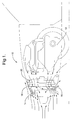
- Figure 1 is a view showing the movable panel in the second position, blocking ram air flow;
- Figure 2 shows the flexible panel in a mediate position, allowing some ram air flow through, but blocking the area below the heat exchangers and fan;
- Figure 3 shows the flexible panel in the first position, allowing a full ram air flow.
-
- Referring first to Figure 1, a typical vehicle, indicated generally at 10, has an
engine 12 located in a compartment near the front of thevehicle 10. At the very front of the vehicle, agrill 14 admits outside air into the engine compartment, and a flow of air also enters through anadditional opening 16 belowgrill 14, which together comprise a general front end air opening. Air will naturally be forced through these openings and around the outside ofengine 12 simply due to the forward motion of thevehicle 10, which is referred to as so called ram air. This, of course, will not be sufficient to cool theengine 12 at idle or low speeds, at least for conventional internal combustion engines, which must be liquid cooled. In that regard,engine 12 is formed with internal coolant passages or jackets, not illustrated, through which liquid coolant is pumped and then pumped to and through aradiator 18 mounted behind thegrill 14. Proximate to radiator 18 (generally just behind, but occasionally in front) is acooling fan 20 which assists the natural ram air flow.Fan 20 provides the only, or majority of, the air flow at idle and low vehicle speeds. Increasingly, in newer vehicle designs,cooling fan 20 is operated by an electric motor, rather than being belt driven, which provides better air flow control, especially at low vehicle speeds and low engine RPMs. Normally, both the forward vehicle speed, and the operation of thefan 20, act in concert to move air rearwardly, that is, toward the engine 12.While thefan 20 may be allowed to turn freely or "windmill" at high vehicle speeds, there would normally be no reason to run it in reverse, and every expectation that doing so would be counter productive, since it would retard the desirable flow of ram air.. - Still referring to Figure 1, heating of the vehicle passenger compartment, indicated generally at 22, is typically achieved by diverting some of the heated engine coolant, the same coolant that is circulated through
radiator 18, through a heater core, as noted above. The heater core would be enclosed in a box like, conventional HVAC housing, not separately illustrated, which would have its own forced air fan to send tempered air into the passenger compartment 22. Given the almost universal popularity of cooling systems, the HVAC housing will typically contain a conventional evaporator as well, which works in conjunction with a condenser mounted in front of theradiator 18, just behind thegrill 14. Conventionally, such an evaporator would receive only expanded, cool refrigerant, and would be used only to cool passenger compartment air, whereas the condenser would receive only heated, pressurized refrigerant, and would be used only to reject heat to the outside air. In the heat pump type of supplementary heating system described above, however, both the evaporator and condenser are dual purpose, and more accurately referred to as simply inside heat exchanger and outside heat exchangers respectively. Such an outside heat exchanger is indicated here at 24. Thefan 20 forces air flow over bothradiator 18 and outside heat exchanger 24, which would be either extracting heat from, or rejecting heat to, that air flow. As noted above, the clear drawback of the outside heat exchanger 24 is that its coefficient of performance is least just when its need is greatest, when the outside air flowing over it is coldest. It is also subject to icing up in such weather, which disrupts air flow through both it andradiator 18. - Referring to Figures 1 and 3, the subject invention deals with the problem of low heat pump coefficient of performance and icing of the outside heat exchanger 24 through the cooperative use of two basic components. One is a selectively reversible motor drive for
fan 20. Reversible electric motors are widely available, although there would normally be no perceived use for one in a radiator fan drive, as noted. The other basic component is a large flexible panel indicated generally at 26, mounted in the engine compartment so as to be rolled back and forth between a vertical length running in front of the outside heat exchanger 24, just behindgrill 14, and a generally horizontal length running below the outside heat exchanger 24,radiator 18, andfan 20. A window 28, large enough to encompass the whole ofgrill 14 and thelower opening 16, is formed in panel 26, which is solid but for that. Panel 26 is adapted to be rolled back and forth by suitable roller, spring and motor mechanisms, like those used in now familiar HVAC housing "film valve" designs, but on a larger scale. As such, window 28 can be located in a first or "normal" position, as shown in Figure 3, where the window 28 is substantially aligned with thegrill 14 andadjacent opening 16, leaving both totally unblocked, to a second position, shown in Figure 1, where outside heat exchanger 24 andradiator 18 are completely blocked from ram air flow. These two capabilities, selective ram air flow blocking, and the potential for reversal offan 20, are used in conjunction as described below. - Referring again to Figure 1, with panel 26 rolled to the second, blocking position shown, normal ram air flow through
grill 14 andopening 16 is blocked. This alone would causeengine 12 andradiator 18 to "warm up" more quickly in cold weather, acting as the equivalent of grill covers or other known cold ram air blocking devices. Where supplementary heat is also provided from the outside heat exchanger 24, however, an additional boost to cold weather heating is provided. Thefan 20 can be reversed, as shown, and air will be pulled from the space aroundengine 12 and blown forwardly, the reverse of its normal path, throughradiator 18 first, then through outside heat exchanger 24, impacting with the solid vertical length of panel 26, and finally exiting through the lower window 28. This forced air flow is aided by extra confinement from an upper substantially horizontal length 30 of the panel 26. It will be recalled that in its "winter" or heating mode, low pressure refrigerant is circulating through the outside heat exchanger 24, ready to extract heat from the air flowing over it. Here, that air is warmer both by virtue of having been drawn from aroundengine 12, and by virtue of having passed throughradiator 18 first. Thus, heat fromradiator 18 that would normally have been "dumped" to the outside is now used to increase the efficiency of the supplementary heat pump system. Likewise, icing of the outside heat exchanger 24 is prevented or reduced, simply by blocking the direct outside cold air flow through it, butradiator 18 is still able to provide engine cooling by virtue of the reversed fan air flow through it. If icing should occur when panel 26 is in its normal position, then it can be moved to the blocking position, withfan 20 reversed, specifically to de ice. Such a method is far preferable to the known method of simply running the heat pump system back in its "summer" mode, which does warm and dec ice the outside heat exchanger 24, but which also cools the passenger compartment 22, an obvious detriment to cold weather comfort. The blocking position of panel 26 and reversal offan 20 could be selected on demand, by a vehicle operator, or automatically, based on outside air temperature and other conditions. - Referring next to Figure 3, the "normal" or first position of panel 26 leaves the outside heat exchanger 24 and
radiator 18 open to the usual ram air flow, as shown, withfan 20 assisting by running in the normal direction, at lower vehicle speeds, or simply free wheeling at high vehicle speeds, so as to not interfere with the normal ram flow. Thus, in winter or summer,radiator 18 would be cooling theengine 12 with the usual rearward air flow. In summer, the outside heat exchanger 24 would also be operating conventionally, as a condenser, dumping heat to the rearward flowing ram air. In winter, outside heat exchanger 24 would be operating in reverse, extracting available heat from the air flow. And, if the outside air were too cold to operate efficiently, the Figure 1 position could be reverted to. - Referring next to Figure 2, the ability to run panel 26 back and forth continuously, rather than just between full "on" and full "off" positions, provides another potential benefit. One problem with normal idle operation of the vehicle, when
fan 20 is running in the normal direction, but the vehicle is stationary or nearly so, is that the heated air that has passed through theradiator 18 is not strongly shed. The heated air can be undesirably recirculated from beneath and back up again through the main air stream created byfan 20. In that situation, the panel 26 can be positioned as shown in Figure 2, with the window 28 partially blocking thegrill 14, and with the solid portion of panel 26 blocking the area beneathradiator 18 and front end heat exchanger 24. Enough outside air can be pulled in by fan 20 (running in the normal direction) tocool radiator 18, and the reduction of hot recirculated air improves the efficiency of bothheat exchangers 18 and 24. - Variations in the disclosed embodiment could be made. Fundamentally, as a method, any selective front end air flow blocking device located in front of the heat exchanger 24 could be used, in conjunction with the reversible fan, to enhance the efficiency of the outside heat exchanger 24. The
fan 20 could be located elsewhere, such as between theradiator 18 and heat exchanger 24, and still provide the desired air flow. Even if a front end heat exchanger 24 were not present, just theradiator 18, the flexible panel 24 could still be used to decrease the engine warm up delay. Therefore, it will be understood that it is not intended to limit the invention to just the embodiment disclosed.
Claims (3)
- For use in an automotive vehicle (10) of the type having a vehicle body with a front end air opening (14) through which outside air is rearwardly forced by the forward motion of said vehicle (10), a liquid coolant radiator (18) mounted within said front end air opening (14) that has heated liquid coolant pumped through it to release heat to the air flowing over it, a means for controlling the forced air flow through said radiator (18), comprising,a flexible film panel (26) adapted to be rolled back and forth continuously over a generally vertical length arrayed in front of said radiator (18), substantially filling said front end air opening (14), and a generally horizontal length arrayed below said outside radiator (18), said film panel (26) having a window (28) therein that can selectively be shifted from a normal, first position within said vertical length, so as to leave said front end opening (14) substantially unblocked, or to a second, blocking position within said horizontal length, so as to substantially cover said front end opening, (14)whereby, said panel (26) can be shifted from the normal, first position, allowing forced rearward air flow through said radiator (18), toward the second position thereby selectively preventing forced rearward air flow through said radiator (18).
- For use in an automotive vehicle (10) of the type having a vehicle body with a front end air opening (14) through which outside air is rearwardly forced by the forward motion of said vehicle (10), a liquid coolant radiator (18) mounted within said front end air opening (14) that has heated liquid coolant pumped through it to release heat to the air flowing over it, and a fan (20) mounted proximate to said radiator (18) to blow air rearwardly through it in addition to the forward motion of said vehicle (10), a means for controlling the forced air flow through said radiator (18), comprising,means for selectively reversing said fan (20), so as to reverse the direction of blown air flow therefrom,a flexible film panel (26) adapted to be rolled back and forth continuously over a generally vertical length arrayed in front of said radiator (18), substantially filling said front end air opening (14), and a generally horizontal length arrayed below said outside radiator (18) and fan (20), said film (26) having a window (28) therein that can selectively be shifted from a normal, first position within said vertical length, so as to leave said front end opening (14) substantially unblocked, or to a second, blocking position within said horizontal length, so as to substantially cover said front end opening (14),whereby, said panel (26) can be shifted from the normal, first position, allowing forced rearward air flow through said radiator (18), toward the second position, thereby selectively preventing forced rearward air flow, and said fan (20) can be concurrently reversed so as to provide a reversed, independent outside air flow over said radiator (18) while said vehicle (10) is moving forwardly.
- For use in an automotive vehicle (10) of the type having a vehicle body with a front end air opening (14) through which outside air is rearwardly forced by the forward motion of said vehicle (10), an air conditioning system outside heat exchanger (24) mounted in said air opening (14) that has pressurized refrigerant selectively pumped through to extract heat energy from the outside air flowing over it, (24) that has heated liquid coolant pumped through it to release heat to the air flowing over it, and a fan (20) mounted proximate to said radiator (18) and outside heat exchanger (24) to simultaneously blow air rearwardly through said outside heat exchanger (24) and (18) in series in addition to the forward motion of said vehicle (10), a means for increasing the efficiency of said outside heat exchanger, comprising,means for selectively reversing said fan (20), so as to reverse the direction of blown air flow therefrom,a flexible film panel (26) adapted to be rolled back and forth continuously over a generally vertical length arrayed in front of said outside heat exchanger (24), substantially filling said front end air opening (14), and a generally horizontal length arrayed below said outside heat exchanger (24), radiator (18) and fan (20), said film panel (26) having a window (28) therein that can selectively be shifted from a normal, first position within said vertical length, so as to leave said front end opening substantially (14) unblocked, or to a second, blocking position within said horizontal length, so as to substantially cover said front end opening (14),whereby, under conditions where said outside air has a low heat energy content, said panel (26) can be shifted from the normal, first position to the second position, thereby substantially preventing forced rearward air flow, while said fan (20) is concurrently reversed, so that outside air is blown in reverse, forwardly through said radiator (18) and outside heat exchanger (24) in series, thereby extracting heat from said radiator (18) before flowing over said outside heat exchanger (24) to increase the efficiency of its heat extraction.
Applications Claiming Priority (2)
| Application Number | Priority Date | Filing Date | Title |
|---|---|---|---|
| US09/824,295 US6390217B1 (en) | 2001-04-02 | 2001-04-02 | Vehicle front end air control |
| US824295 | 2001-04-02 |
Publications (3)
| Publication Number | Publication Date |
|---|---|
| EP1247682A2 true EP1247682A2 (en) | 2002-10-09 |
| EP1247682A3 EP1247682A3 (en) | 2004-12-15 |
| EP1247682B1 EP1247682B1 (en) | 2008-05-21 |
Family
ID=25241049
Family Applications (1)
| Application Number | Title | Priority Date | Filing Date |
|---|---|---|---|
| EP02075976A Expired - Lifetime EP1247682B1 (en) | 2001-04-02 | 2002-03-13 | Vehicle front end air control |
Country Status (3)
| Country | Link |
|---|---|
| US (1) | US6390217B1 (en) |
| EP (1) | EP1247682B1 (en) |
| DE (1) | DE60226660D1 (en) |
Cited By (2)
| Publication number | Priority date | Publication date | Assignee | Title |
|---|---|---|---|---|
| RU2372228C1 (en) * | 2008-02-20 | 2009-11-10 | Открытое акционерное общество Научно-исследовательский и конструкторско-технологический институт подвижного состава (ОАО "ВНИКТИ") | Control method of internal combustion engine cooling system |
| CN110173340A (en) * | 2019-06-03 | 2019-08-27 | 广西玉柴机器股份有限公司 | The back-flow preventer of automobile hot wind |
Families Citing this family (60)
| Publication number | Priority date | Publication date | Assignee | Title |
|---|---|---|---|---|
| US7927684B2 (en) * | 2000-01-19 | 2011-04-19 | Saint-Gobain Performance Plastics Corporation | Low coefficient of friction polymer film |
| US7121368B2 (en) * | 2000-05-09 | 2006-10-17 | Mackelvie Winston | Bi-directional automotive cooling fan |
| DE10048531C1 (en) * | 2000-09-30 | 2002-04-25 | Porsche Ag | Cooling air duct for motor vehicles |
| US6634448B2 (en) * | 2001-07-20 | 2003-10-21 | Mark Bland | Riding lawn mower with improved radiator system |
| US7028791B2 (en) * | 2001-08-23 | 2006-04-18 | General Motors Corporation | Mobile chassis and interchangeable vehicle body with a heating, ventilation and air conditioning system |
| JP3577018B2 (en) * | 2001-08-31 | 2004-10-13 | 本田技研工業株式会社 | Air intake structure around the front grill of the vehicle |
| JP2005053464A (en) * | 2003-07-24 | 2005-03-03 | Denso Corp | Vehicle front end structure |
| US7000575B2 (en) * | 2004-06-02 | 2006-02-21 | Generac Power Systems, Inc. | Method and apparatus for reducing fan noise in an electrical generator |
| DE102005044559A1 (en) * | 2005-09-17 | 2007-03-29 | Behr Gmbh & Co. Kg | Arrangement for cooling an internal combustion engine of a motor vehicle, in particular cooling module |
| US7644792B2 (en) * | 2006-01-06 | 2010-01-12 | Hamilton Sundstrand | Motor cooling system |
| DE102006014443A1 (en) * | 2006-03-29 | 2007-10-04 | Bayerische Motoren Werke Ag | Motor vehicle`s front end, has auxiliary inlet provided within track facing region of end, where inlet is provided in laterally external region before front wheels of motor vehicle, and bumper covering is pulled downward |
| US7608121B2 (en) * | 2006-08-17 | 2009-10-27 | Delphi Technologies, Inc. | HVAC system with moving filter |
| US8910705B2 (en) | 2008-05-27 | 2014-12-16 | Toyota Motor Engineering & Manufacturing North America, Inc. | Radiator fan control for heat pump HVAC |
| US20100051711A1 (en) * | 2008-08-29 | 2010-03-04 | Nissan Technical Center North America, Inc. | Reversible cooling fan for vehicle and method for controlling direction of rotation |
| US8104559B2 (en) * | 2008-09-22 | 2012-01-31 | Clark Equipment Company | Multiple air flow paths using single axial fan |
| JP4909972B2 (en) * | 2008-10-02 | 2012-04-04 | 本田技研工業株式会社 | Cooling device for vehicle engine |
| FR2950574B1 (en) * | 2009-09-29 | 2012-03-23 | Valeo Systemes Thermiques | THERMAL EXCHANGE BLOCK FOR MOTOR VEHICLE |
| US10393005B2 (en) | 2010-06-17 | 2019-08-27 | Gm Global Technology Operations, Inc. | Fuel efficient powertrain cooling systems and radiator modules |
| DE102010036440B4 (en) * | 2010-07-16 | 2024-03-28 | Dr. Ing. H.C. F. Porsche Aktiengesellschaft | Cooling air duct for a motor vehicle |
| JP5131410B2 (en) * | 2010-08-03 | 2013-01-30 | トヨタ自動車株式会社 | Vehicle cooling structure |
| US20120097465A1 (en) * | 2010-10-22 | 2012-04-26 | Gm Global Technology Operations, Inc. | System and method for controlling a shutter in a vehicle via a cooling fan duty-cycle |
| US20120097464A1 (en) * | 2010-10-22 | 2012-04-26 | Gm Global Technology Operations, Inc. | Control of a shutter via bi-directional communication using a single wire |
| DE102011013856B4 (en) * | 2011-03-14 | 2013-08-08 | Audi Ag | Device and method for variable flow of a heat exchanger module |
| US9061585B2 (en) * | 2011-03-31 | 2015-06-23 | Fuji Jukogyo Kabushiki Kaisha | Cooling air introduction apparatus for vehicle |
| US20130081888A1 (en) * | 2011-09-30 | 2013-04-04 | GM Global Technology Operations LLC | Reconfigurable baseline opening for under-hood airflow |
| JP5655952B2 (en) * | 2011-10-12 | 2015-01-21 | トヨタ自動車株式会社 | Vehicle front structure |
| WO2013073262A1 (en) * | 2011-11-15 | 2013-05-23 | トヨタ自動車株式会社 | Cooling airflow introduction structure |
| US8967311B2 (en) * | 2011-12-01 | 2015-03-03 | Paccar Inc. | Directed gas systems for improving aerodynamics of a vehicle in cross wind conditions |
| US8807630B2 (en) * | 2011-12-06 | 2014-08-19 | Mark Rode | Variably openable radiator cowling, shroud, or fairing for over the road vehicles and the like |
| GB201121608D0 (en) * | 2011-12-15 | 2012-01-25 | Agco Sa | Agriculture tractor front end installation |
| US8708075B2 (en) * | 2012-01-16 | 2014-04-29 | Honda Motor Co., Ltd. | Front end structure for vehicle |
| US9573458B2 (en) * | 2012-10-03 | 2017-02-21 | Magna, International Inc. | Spring operated back-up/fail-safe module for active grille shutter systems |
| US9664104B2 (en) | 2012-10-30 | 2017-05-30 | Ford Global Technologies, Llc | Condensation control in a charge air cooler by controlling charge air cooler temperature |
| US9988969B2 (en) * | 2013-04-29 | 2018-06-05 | Hanon Systems | Fluid management system for a heat exchanger of a vehicle air conditioning system |
| US20150041229A1 (en) * | 2013-08-08 | 2015-02-12 | Honda Motor Co., Ltd. | Front end arrangement with active radiator damper and active radiator control method |
| US9752491B2 (en) * | 2013-10-07 | 2017-09-05 | Denso International America, Inc. | Powered air ram with energy recovery |
| DE102013112825A1 (en) * | 2013-11-20 | 2015-05-21 | Valeo Klimasysteme Gmbh | Front module of a vehicle |
| KR102011275B1 (en) * | 2014-02-21 | 2019-08-21 | 한온시스템 주식회사 | Installing Structure of external heat exchanger |
| DE102014110198A1 (en) * | 2014-07-21 | 2016-01-21 | Dr. Ing. H.C. F. Porsche Aktiengesellschaft | Bug of a motor vehicle |
| US9969342B2 (en) * | 2015-03-26 | 2018-05-15 | Ford Global Technologies Llc | Body-on-frame bumper step pad with seal between bumper beam and radiator grill |
| CN107921861A (en) * | 2015-08-20 | 2018-04-17 | 株式会社电装 | Cooling device |
| FR3042458B1 (en) * | 2015-10-15 | 2018-07-13 | Valeo Systemes Thermiques | Air inlet control device with remote actuator |
| JP6394580B2 (en) * | 2015-12-11 | 2018-09-26 | 株式会社デンソー | Vehicle control device |
| US9744848B2 (en) | 2015-12-21 | 2017-08-29 | Thunder Power New Energy Vehicle Development Company Limited | Vehicle radiator V type layout |
| US9469187B1 (en) * | 2015-12-21 | 2016-10-18 | Thunder Power Hong Kong Ltd. | Vehicle radiator V type layout |
| FR3057814B1 (en) * | 2016-10-26 | 2019-12-13 | Valeo Systemes Thermiques | FRONT PANEL MODULE FOR MOTOR VEHICLE |
| GB2555864B (en) | 2016-11-15 | 2020-01-08 | Perkins Engines Co Ltd | Control system for thermal management of an engine aftertreatment device |
| US11512623B2 (en) | 2017-07-17 | 2022-11-29 | Kohler Co. | Apparatus for controlling cooling airflow to an intenral combustion engine, and engines and methods utilizing the same |
| JP6834874B2 (en) * | 2017-09-19 | 2021-02-24 | 株式会社デンソー | Heat exchange system |
| FR3076603B1 (en) * | 2018-01-09 | 2020-05-22 | Valeo Systemes Thermiques | COOLING UNIT FOR MOTOR VEHICLE |
| DE102018114499B4 (en) * | 2018-06-18 | 2021-02-11 | Dr. Ing. H.C. F. Porsche Aktiengesellschaft | Motor vehicle bug |
| DE102018132406A1 (en) * | 2018-12-17 | 2020-06-18 | Volkswagen Aktiengesellschaft | Flow guidance arrangement for a vehicle |
| DE102019117986B4 (en) * | 2019-07-03 | 2021-06-24 | Hbpo Gmbh | Device for closing a motor vehicle cooling module |
| US11648835B2 (en) | 2020-03-19 | 2023-05-16 | Toyota Motor Engineering & Manufacturing North America, Inc. | Smart grille shutter in connected vehicle |
| US11890923B2 (en) * | 2020-06-24 | 2024-02-06 | Honda Motor Co., Ltd. | Upper body heat exchanger for vehicles |
| US11486294B2 (en) * | 2020-09-04 | 2022-11-01 | Transportation Ip Holdings, Llc | Control system and method for a fan |
| FR3114048B1 (en) * | 2020-09-14 | 2022-12-30 | Valeo Systemes Thermiques | Heat exchange module and corresponding motor vehicle |
| DE102020125917B4 (en) * | 2020-10-02 | 2023-07-13 | Montaplast Gesellschaft mit beschränkter Haftung | Air flow control for an internal combustion engine |
| FR3129197B1 (en) * | 2021-11-15 | 2024-03-01 | Valeo Systemes Thermiques | Thermal conditioning system |
| US20240149661A1 (en) * | 2022-11-09 | 2024-05-09 | Rivian Ip Holdings, Llc | Thermal management for vehicles |
Family Cites Families (19)
| Publication number | Priority date | Publication date | Assignee | Title |
|---|---|---|---|---|
| US1161444A (en) * | 1914-01-09 | 1915-11-23 | Judson H Boughton | Curtain. |
| US1165461A (en) * | 1914-02-20 | 1915-12-28 | William Stein | Automobile radiator-protector. |
| US1261855A (en) * | 1916-12-04 | 1918-04-09 | Harry A Rishel | Automobile-radiator shield. |
| US1248073A (en) * | 1916-12-29 | 1917-11-27 | Rudolph Carlson | Heat-controller for automobile-radiators. |
| US1268892A (en) * | 1917-02-01 | 1918-06-11 | August Sunnen | Automobile-radiator protector. |
| US1404527A (en) * | 1917-02-06 | 1922-01-24 | Gerhard R Janssen | Radiator-cover-operating means |
| US1291807A (en) * | 1918-01-30 | 1919-01-21 | William M Edmont | Radiator-cover and temperature-regulator. |
| US1379308A (en) * | 1918-12-26 | 1921-05-24 | George G Marshall | Air-controlling device for automobile-radiators |
| US1338223A (en) * | 1919-01-13 | 1920-04-27 | Heath Samuel | Automatic screen |
| US1367031A (en) * | 1919-07-05 | 1921-02-01 | Fedders Mfg Co Inc | Air-regulator for radiators |
| US1771714A (en) * | 1928-03-21 | 1930-07-29 | Edward C Lawrence | Radiator cover |
| US1818328A (en) * | 1930-01-23 | 1931-08-11 | Isaac C Hess | Winter front for automobile radiators |
| US1823141A (en) * | 1930-03-31 | 1931-09-15 | Case Co J I | Curtain device for radiators |
| US2254459A (en) * | 1939-06-20 | 1941-09-02 | Swanda Frank | Radiator protector |
| US2246823A (en) * | 1940-04-25 | 1941-06-24 | Carl J Vollberg | Radiator protector |
| JPS61145315A (en) * | 1984-12-20 | 1986-07-03 | Mitsubishi Motors Corp | Method of cooling engine room in vehicle |
| US4750549A (en) * | 1986-06-09 | 1988-06-14 | Autotron Products, Inc. | Radiator grille cover with adjustable center openings |
| USRE34907E (en) * | 1988-11-14 | 1995-04-18 | Lund Industries Incorporated | Air flow engagement panel element for the grill of a motor vehicle |
| US6076488A (en) * | 1997-03-17 | 2000-06-20 | Shin Caterpillar Mitsubishi Ltd. | Cooling device for a construction machine |
-
2001
- 2001-04-02 US US09/824,295 patent/US6390217B1/en not_active Expired - Lifetime
-
2002
- 2002-03-13 EP EP02075976A patent/EP1247682B1/en not_active Expired - Lifetime
- 2002-03-13 DE DE60226660T patent/DE60226660D1/en not_active Expired - Lifetime
Non-Patent Citations (1)
| Title |
|---|
| None |
Cited By (2)
| Publication number | Priority date | Publication date | Assignee | Title |
|---|---|---|---|---|
| RU2372228C1 (en) * | 2008-02-20 | 2009-11-10 | Открытое акционерное общество Научно-исследовательский и конструкторско-технологический институт подвижного состава (ОАО "ВНИКТИ") | Control method of internal combustion engine cooling system |
| CN110173340A (en) * | 2019-06-03 | 2019-08-27 | 广西玉柴机器股份有限公司 | The back-flow preventer of automobile hot wind |
Also Published As
| Publication number | Publication date |
|---|---|
| DE60226660D1 (en) | 2008-07-03 |
| EP1247682A3 (en) | 2004-12-15 |
| EP1247682B1 (en) | 2008-05-21 |
| US6390217B1 (en) | 2002-05-21 |
Similar Documents
| Publication | Publication Date | Title |
|---|---|---|
| US6390217B1 (en) | Vehicle front end air control | |
| US5284025A (en) | Air conditioning apparatus for an electrically-powered motor vehicle | |
| KR100755951B1 (en) | Seat air conditioner for vehicle | |
| EP2497662A2 (en) | Heat pump system for vehicle | |
| US20030019232A1 (en) | Air conditioner for automobile | |
| JP2019015498A (en) | Defrosting device of heat exchanger and defrosting method | |
| WO2013105201A1 (en) | Vehicle air conditioner | |
| JP2017190096A (en) | Vehicle cooling system | |
| CN110072717B (en) | Air conditioner for vehicle | |
| WO2013105203A1 (en) | Vehicle air-conditioning device | |
| GB2120379A (en) | Heating and ventilating device for the passenger compartment of a motor vehicle | |
| JP4106297B2 (en) | Vehicle heat exchanger | |
| CN115320326A (en) | Thermal management system | |
| KR101201301B1 (en) | Seat air conditioner for vehicle | |
| US20260109197A1 (en) | Heat pump system for vehicle | |
| JPH04163230A (en) | Cooling device | |
| JP2001001750A (en) | Air conditioner for vehicle | |
| JP2007186047A (en) | Vehicular heat exchanger | |
| KR101309194B1 (en) | A cold thermal storage system | |
| CN2890782Y (en) | Evaporator assembly of air conditioner of middle-size coach | |
| KR101264616B1 (en) | A cold thermal storage system | |
| KR101200755B1 (en) | Seat air conditioner for vehicle | |
| JP2003314281A (en) | Engine coolant circulation system | |
| JPH05162536A (en) | Air conditioner for electric vehicle | |
| JPH1058965A (en) | Heat pump-type air conditioner for automobile |
Legal Events
| Date | Code | Title | Description |
|---|---|---|---|
| PUAI | Public reference made under article 153(3) epc to a published international application that has entered the european phase |
Free format text: ORIGINAL CODE: 0009012 |
|
| AK | Designated contracting states |
Kind code of ref document: A2 Designated state(s): AT BE CH CY DE DK ES FI FR GB GR IE IT LI LU MC NL PT SE TR |
|
| AX | Request for extension of the european patent |
Free format text: AL;LT;LV;MK;RO;SI |
|
| PUAL | Search report despatched |
Free format text: ORIGINAL CODE: 0009013 |
|
| AK | Designated contracting states |
Kind code of ref document: A3 Designated state(s): AT BE CH CY DE DK ES FI FR GB GR IE IT LI LU MC NL PT SE TR |
|
| AX | Request for extension of the european patent |
Extension state: AL LT LV MK RO SI |
|
| RIC1 | Information provided on ipc code assigned before grant |
Ipc: 7B 60K 11/08 A Ipc: 7F 01P 7/10 B |
|
| 17P | Request for examination filed |
Effective date: 20050615 |
|
| AKX | Designation fees paid |
Designated state(s): DE FR GB |
|
| 17Q | First examination report despatched |
Effective date: 20051221 |
|
| GRAP | Despatch of communication of intention to grant a patent |
Free format text: ORIGINAL CODE: EPIDOSNIGR1 |
|
| GRAS | Grant fee paid |
Free format text: ORIGINAL CODE: EPIDOSNIGR3 |
|
| GRAA | (expected) grant |
Free format text: ORIGINAL CODE: 0009210 |
|
| AK | Designated contracting states |
Kind code of ref document: B1 Designated state(s): DE FR GB |
|
| REG | Reference to a national code |
Ref country code: GB Ref legal event code: FG4D |
|
| REF | Corresponds to: |
Ref document number: 60226660 Country of ref document: DE Date of ref document: 20080703 Kind code of ref document: P |
|
| PLBE | No opposition filed within time limit |
Free format text: ORIGINAL CODE: 0009261 |
|
| STAA | Information on the status of an ep patent application or granted ep patent |
Free format text: STATUS: NO OPPOSITION FILED WITHIN TIME LIMIT |
|
| 26N | No opposition filed |
Effective date: 20090224 |
|
| REG | Reference to a national code |
Ref country code: DE Ref legal event code: R082 Ref document number: 60226660 Country of ref document: DE Representative=s name: BRP RENAUD UND PARTNER MBB RECHTSANWAELTE PATE, DE Ref country code: DE Ref legal event code: R082 Ref document number: 60226660 Country of ref document: DE Representative=s name: BRP RENAUD UND PARTNER MBB, DE Ref country code: DE Ref legal event code: R081 Ref document number: 60226660 Country of ref document: DE Owner name: MAHLE INTERNATIONAL GMBH, DE Free format text: FORMER OWNER: DELPHI TECHNOLOGIES, INC., TROY, MICH., US |
|
| REG | Reference to a national code |
Ref country code: FR Ref legal event code: PLFP Year of fee payment: 15 |
|
| REG | Reference to a national code |
Ref country code: GB Ref legal event code: 732E Free format text: REGISTERED BETWEEN 20161208 AND 20161214 |
|
| REG | Reference to a national code |
Ref country code: FR Ref legal event code: PLFP Year of fee payment: 16 |
|
| REG | Reference to a national code |
Ref country code: FR Ref legal event code: TP Owner name: MAHLE INTERNATIONAL GMBH, DE Effective date: 20180103 |
|
| REG | Reference to a national code |
Ref country code: FR Ref legal event code: PLFP Year of fee payment: 17 |
|
| PGFP | Annual fee paid to national office [announced via postgrant information from national office to epo] |
Ref country code: GB Payment date: 20190327 Year of fee payment: 18 |
|
| PGFP | Annual fee paid to national office [announced via postgrant information from national office to epo] |
Ref country code: DE Payment date: 20190528 Year of fee payment: 18 |
|
| PGFP | Annual fee paid to national office [announced via postgrant information from national office to epo] |
Ref country code: FR Payment date: 20190903 Year of fee payment: 18 |
|
| REG | Reference to a national code |
Ref country code: DE Ref legal event code: R119 Ref document number: 60226660 Country of ref document: DE |
|
| PG25 | Lapsed in a contracting state [announced via postgrant information from national office to epo] |
Ref country code: FR Free format text: LAPSE BECAUSE OF NON-PAYMENT OF DUE FEES Effective date: 20200331 Ref country code: DE Free format text: LAPSE BECAUSE OF NON-PAYMENT OF DUE FEES Effective date: 20201001 |
|
| GBPC | Gb: european patent ceased through non-payment of renewal fee |
Effective date: 20200313 |
|
| PG25 | Lapsed in a contracting state [announced via postgrant information from national office to epo] |
Ref country code: GB Free format text: LAPSE BECAUSE OF NON-PAYMENT OF DUE FEES Effective date: 20200313 |