EP1247666B1 - Heat exchanger and vehicle heating or air conditioning device comprising such a heat exchanger - Google Patents
Heat exchanger and vehicle heating or air conditioning device comprising such a heat exchanger Download PDFInfo
- Publication number
- EP1247666B1 EP1247666B1 EP02004904A EP02004904A EP1247666B1 EP 1247666 B1 EP1247666 B1 EP 1247666B1 EP 02004904 A EP02004904 A EP 02004904A EP 02004904 A EP02004904 A EP 02004904A EP 1247666 B1 EP1247666 B1 EP 1247666B1
- Authority
- EP
- European Patent Office
- Prior art keywords
- heat exchanger
- discs
- flow passages
- exchanger according
- medium
- Prior art date
- Legal status (The legal status is an assumption and is not a legal conclusion. Google has not performed a legal analysis and makes no representation as to the accuracy of the status listed.)
- Expired - Lifetime
Links
Images


Classifications
-
- F—MECHANICAL ENGINEERING; LIGHTING; HEATING; WEAPONS; BLASTING
- F28—HEAT EXCHANGE IN GENERAL
- F28F—DETAILS OF HEAT-EXCHANGE AND HEAT-TRANSFER APPARATUS, OF GENERAL APPLICATION
- F28F17/00—Removing ice or water from heat-exchange apparatus
- F28F17/005—Means for draining condensates from heat exchangers, e.g. from evaporators
-
- B—PERFORMING OPERATIONS; TRANSPORTING
- B60—VEHICLES IN GENERAL
- B60H—ARRANGEMENTS OF HEATING, COOLING, VENTILATING OR OTHER AIR-TREATING DEVICES SPECIALLY ADAPTED FOR PASSENGER OR GOODS SPACES OF VEHICLES
- B60H1/00—Heating, cooling or ventilating [HVAC] devices
- B60H1/00321—Heat exchangers for air-conditioning devices
- B60H1/00328—Heat exchangers for air-conditioning devices of the liquid-air type
-
- F—MECHANICAL ENGINEERING; LIGHTING; HEATING; WEAPONS; BLASTING
- F28—HEAT EXCHANGE IN GENERAL
- F28D—HEAT-EXCHANGE APPARATUS, NOT PROVIDED FOR IN ANOTHER SUBCLASS, IN WHICH THE HEAT-EXCHANGE MEDIA DO NOT COME INTO DIRECT CONTACT
- F28D1/00—Heat-exchange apparatus having stationary conduit assemblies for one heat-exchange medium only, the media being in contact with different sides of the conduit wall, in which the other heat-exchange medium is a large body of fluid, e.g. domestic or motor car radiators
- F28D1/02—Heat-exchange apparatus having stationary conduit assemblies for one heat-exchange medium only, the media being in contact with different sides of the conduit wall, in which the other heat-exchange medium is a large body of fluid, e.g. domestic or motor car radiators with heat-exchange conduits immersed in the body of fluid
- F28D1/03—Heat-exchange apparatus having stationary conduit assemblies for one heat-exchange medium only, the media being in contact with different sides of the conduit wall, in which the other heat-exchange medium is a large body of fluid, e.g. domestic or motor car radiators with heat-exchange conduits immersed in the body of fluid with plate-like or laminated conduits
- F28D1/0308—Heat-exchange apparatus having stationary conduit assemblies for one heat-exchange medium only, the media being in contact with different sides of the conduit wall, in which the other heat-exchange medium is a large body of fluid, e.g. domestic or motor car radiators with heat-exchange conduits immersed in the body of fluid with plate-like or laminated conduits the conduits being formed by paired plates touching each other
- F28D1/0325—Heat-exchange apparatus having stationary conduit assemblies for one heat-exchange medium only, the media being in contact with different sides of the conduit wall, in which the other heat-exchange medium is a large body of fluid, e.g. domestic or motor car radiators with heat-exchange conduits immersed in the body of fluid with plate-like or laminated conduits the conduits being formed by paired plates touching each other the plates having lateral openings therein for circulation of the heat-exchange medium from one conduit to another
- F28D1/0333—Heat-exchange apparatus having stationary conduit assemblies for one heat-exchange medium only, the media being in contact with different sides of the conduit wall, in which the other heat-exchange medium is a large body of fluid, e.g. domestic or motor car radiators with heat-exchange conduits immersed in the body of fluid with plate-like or laminated conduits the conduits being formed by paired plates touching each other the plates having lateral openings therein for circulation of the heat-exchange medium from one conduit to another the plates having integrated connecting members
-
- F—MECHANICAL ENGINEERING; LIGHTING; HEATING; WEAPONS; BLASTING
- F28—HEAT EXCHANGE IN GENERAL
- F28D—HEAT-EXCHANGE APPARATUS, NOT PROVIDED FOR IN ANOTHER SUBCLASS, IN WHICH THE HEAT-EXCHANGE MEDIA DO NOT COME INTO DIRECT CONTACT
- F28D9/00—Heat-exchange apparatus having stationary plate-like or laminated conduit assemblies for both heat-exchange media, the media being in contact with different sides of a conduit wall
- F28D9/0031—Heat-exchange apparatus having stationary plate-like or laminated conduit assemblies for both heat-exchange media, the media being in contact with different sides of a conduit wall the conduits for one heat-exchange medium being formed by paired plates touching each other
- F28D9/0037—Heat-exchange apparatus having stationary plate-like or laminated conduit assemblies for both heat-exchange media, the media being in contact with different sides of a conduit wall the conduits for one heat-exchange medium being formed by paired plates touching each other the conduits for the other heat-exchange medium also being formed by paired plates touching each other
-
- F—MECHANICAL ENGINEERING; LIGHTING; HEATING; WEAPONS; BLASTING
- F28—HEAT EXCHANGE IN GENERAL
- F28F—DETAILS OF HEAT-EXCHANGE AND HEAT-TRANSFER APPARATUS, OF GENERAL APPLICATION
- F28F2275/00—Fastening; Joining
- F28F2275/04—Fastening; Joining by brazing
Definitions
- the invention relates to a heat exchanger in disk construction according to the preamble of claim 1, as well as a thus equipped heating or air conditioning for a motor vehicle.
- An air conditioner as known for example from DE 198 04 389, has an evaporator in so-called. Disk construction.
- the evaporator has first, formed from a pair of disks flow channels for a refrigerant of the air conditioner, as well as between each adjacent pairs of disks arranged corrugated fins, which are flowed around by the air to be cooled.
- Disk evaporators are cuboid and are used in the air conditioner between a fan and a radiator for cooling the air to be conveyed into the passenger compartment.
- the heat exchanger according to the invention is constructed in disk construction, wherein between each two disks at least a first flow channel for a first medium and between two pairs of disks a plurality of parallel-connected second flow channels are arranged for a second medium, wherein the second parallel flow channels through a respective disk adjacent disc pairs are formed.
- the production is simplified because the entire heat exchanger can be built by simply stacking the discs. Filigree corrugated ribs no longer have to be provided between the disk pairs, which also reduces manufacturing costs. Another advantage is that solder joints between the disc and corrugated rib omitted. This eliminates the through Soldering solder joint-associated problem for a good heat transfer, whereby the heat transfer is improved.
- the second flow channels of the heat exchanger according to the invention have an arcuate course, so that the air can be deflected in a desired direction, whereby a more compact construction, in particular of the heat exchanger according to the invention containing air conditioning is possible.
- the heat exchanger performs both the function of cooling or heating the air flowing through, as well as a guide of the air. As a result, at least to a certain extent air deflections on the air side before and / or after the heat exchanger can be dispensed with.
- the heating or air conditioning, or the air duct housing this system can be made more compact.
- first flow channels carrying the first medium which is a refrigerant of the air conditioning system when the heat exchanger is preferably used as an evaporator
- first medium which is a refrigerant of the air conditioning system when the heat exchanger is preferably used as an evaporator
- the area available for the connection of adjacent panes is relatively large. This results in a high pressure stability of the first flow channels, which makes the use of the heat exchanger in an air conditioner with CO 2 as a refrigerant or other refrigerants that work at high pressures possible.
- the second flow channels preferably extend in a circular arc. This results in the air despite deflection low pressure losses.
- an inflow surface and an exit surface of the air can advantageously be arranged at an angle ⁇ to one another.
- the angle ⁇ is about 90 °.
- a plurality of parallel first flow channels are formed by a pair of disks, so that a refrigerant flowing through the first channels as uniformly as possible tempered the disk pair on its entire embedding.
- the channels are approximately the same length, in order to obtain approximately the same pressure drop in each channel.
- the first flow channels at least in regions, preferably have a meandering course.
- the discs on a first side channel-like depressions which form the first flow channels when connecting adjacent discs with their first sides to a pair of discs.
- At least one groove-like web and at least one spring-like groove are arranged along the depressions.
- the webs of a disc come into the grooves of the other disc fit exactly into each other and can be connected together, preferably soldered or glued.
- the discs have webs projecting from their second side. Adjacent discs can be connected to one another via the webs.
- adjacent disks are formed almost mirror-symmetrical. Only in their connection areas adjacent disks are complementary formed for optimal connection of the discs. In principle, only two different types of disks are needed to produce the heat exchanger.
- recesses can be impressed in the embossing of the discs at the downstream end of the second flow channels, at which, when using the heat exchanger as an evaporator, resulting condensate can run off. Special measures for a condensate drain can be dispensed with.
- the discs are made of aluminum, whereby the weight is kept low and good processability is given. It is also conceivable that the discs consist of a non-ferrous metal.
- the heat exchanger according to the invention in an air conditioner that works with CO 2 as a refrigerant can be used as an evaporator, as by the surface soldering of adjacent disks with their first sides to form the first flow channels for the CO 2 and in particular by the optionally provided intermeshing Grooves and webs, the evaporator improves the high system pressures in a CO 2 plant can withstand.
- space can be saved in the manner already described.
- a very compact heating or air conditioning is obtained when the heat exchanger deflects the air by about 90 degrees.
- inventive heat exchanger 10 comprises first and second discs 12 and 14, which substantially build the entire heat exchanger by alternately stacked stacked or strung together and adjacent discs are soldered or glued together, wherein alternately first and second flow channels 16 and 18 are formed.
- the heat exchanger 10 shown can be used as an evaporator of a refrigerant circuit, which is why the flow channels 16 are provided for guiding a refrigerant and the flow channels 18 for guiding air.
- the discs 12 and 14 are formed substantially mirror symmetrical and have an outer shape, which corresponds in the embodiment in about a quarter circle (Fig. 3).
- the discs 12 and 14 At a center 20 of the circle facing the end 20, the discs 12 and 14, two through holes 22 and 24, each through hole 22 and 24 each having a collar 26 and 28, so that in the assembled state of the heat exchanger 10, the collar adjacent discs connected to each other , In particular, are soldered, so that the mutually aligned through holes 22 and 24 each form a plenum for a first medium.
- a feed connection or drain connection not shown, the first medium to the heat exchanger 10 is added or worn.
- the first flow channels 16 are formed by channel-like depressions 30 and 32, respectively, on a first side 34 and 36 of the first and / or second disks 12 and 14 (FIG. 5).
- the channel-like recesses 30 and 32 form the first flow channels 16.
- At least one spring-like web 38 and at least one groove-like groove 40 are provided along the depressions 30 and 32, wherein when joining the first sides 34 and 36, the webs 38 of a disc 12 and 14 in the Grooves 40 of the other disc 14 or 12 fit into each other to lie down and connected to each other, in particular soldered, can (Fig. 5).
- the discs 12 and 14 are thus formed complementary to each other.
- a plurality of the first flow channels 16 are formed by a pair of discs 13, wherein the flow channels 16 are connected in parallel in a pair of discs and are preferably approximately the same length, to which extend the further inwardly extending flow channels 16 at least partially meandering.
- first and / or second disc 12 and 14 On a second side 42 and 44 of the first and / or second disc 12 and 14, webs 46 and 48 projecting from the second side are arranged (FIG. 5). Adjacent discs 12 and 14 are connected to each other via the webs 46 and 48, for example, soldered or glued, wherein the connection along complementary to each other formed end edges 47 and 49 of the webs 46 and 48 takes place. The shape of the end edges is chosen such that when two discs 14 and 12 a montage friendly self-centering takes place.
- the disks 14 and 12 which are connected to one another via their second sides 42 and 44 and the webs 46 and 48 form the second flow channels 18 (FIG. 5).
- the second flow channels 18, which are formed between two disk pairs 13, are connected in parallel and open towards their ends, as can be seen in particular in FIG.
- the second flow channels 18 according to the outer shape of the discs 12 and 14 arcuate, in particular circular arc-shaped, formed (Fig. 4).
- the individual second flow channels 18 are of different lengths and with a greater distance from the inlet for the first medium, ie from the passage opening 22, longer, so that in the vicinity of the inlet, where a relatively large temperature difference between the two media, the flow channels 18 are relatively short, and therefore the heat exchange needs to take place only over a shorter path.
- auxiliary ribs 64 may be disposed in the shorter flow passages 18 near the inlet to enhance heat exchange in the shorter flow passages, as indicated in FIG. 5 in the leftmost flow passage 18.
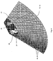
- the ends of the flow channels 18 are arranged on the one hand on an air inflow side 50 and on the other hand on an air outlet side 52 (FIG. 1).
- the air flowing in the direction 54 enters the flow channels 18 on the air inflow side 50 and undergoes a change in direction as it flows through the heat exchanger 10 and exits the heat exchanger 10 on the air outlet side 52 in the direction 56.
- the air outlet surface 52 is in a diaper ⁇ of about 90 ° to the Lucasanström preparation 50. Other angles are readily conceivable.
- these condensate drainage aids integrated in the panes 12, 14 have recesses 60 in the form of recesses 60 by means of which condensate water settling in the heat exchanger 10 can drain off or drain off (FIG. 6).
- the condensate drainage aids may also have another suitable shape.
- vortex generators 62 can be arranged on the webs 46, 48, which cause a turbulence of the air flowing through the flow channels 18 and thus an improved heat transfer.
- the discs 12 and 14 of the heat exchanger 10 are preferably made of aluminum and are soldered together, which can be done for example in a soldering oven.
- the discs can also be glued together or consist of a non-ferrous metal.
- the heat exchanger 10 is thus constructed in the simplest way from only two different discs 12 and 14. It is also possible to provide at the ends of the heat exchanger 10 flat end plates 62 or just form the outermost discs on one side.
- the heat exchanger 10 according to the invention is preferably used in heating or air conditioning systems, in particular in air conditioning systems, in which CO 2 is used as a refrigerant.
- Fig. 7 an embodiment is shown, in which the heat exchanger 10 is used as the evaporator 102.
- To be conditioned air is supplied from a radial fan 104, not shown directly to the inflow surface 106 of the evaporator 102.
- the air is cooled and simultaneously deflected by about 90 °.
- a mixing flap 112 cold air exiting from the evaporator 102 can be supplied to a heating element 110 and supplied by the heating element 110 to an air mixing chamber 108 as warm air.
- the radiator 110 is formed in the disc construction according to the invention.
- Via bypass flap 144 cold air can be conducted past the heating element 110 and supplied to the air mixing chamber 108.
- the hot air and the cold air are mixed to obtain air of a desired temperature.
- a defrost air passage 118, a foot air passage 122, and an air passage 148 branch to vents in the middle plane of the vehicle.
- the ones from Air mixing chamber 108 branching air ducts are each closed with air dampers.
Abstract
Description
Die Erfindung betrifft einen Wärmetauscher in Scheibenbauweise gemäß dem Oberbegriff des Anspruchs 1, sowie eine damit ausgerüstete Heizungs- oder Klimaanlage für ein Kraftfahrzeug.The invention relates to a heat exchanger in disk construction according to the preamble of
Eine Klimaanlage, wie sie beispielsweise aus der DE 198 04 389 bekannt ist, weist einen Verdampfer in sog. Scheibenbauweise auf. Der Verdampfer weist erste, aus jeweils einem Paar Scheiben gebildete Strömungskanäle für ein Kältemittel der Klimaanlage auf, sowie zwischen jeweils benachbarten Scheibenpaaren angeordnete Wellrippen, die von der zu kühlenden Luft umströmt werden. Derartige bekannte, sog. Scheibenverdampfer sind quaderförmig aufgebaut und werden in der Klimaanlage zwischen einem Gebläse und einem Heizkörper zur Kühlung der in den Fahrgastraum zu fördernden Luft eingesetzt.An air conditioner, as known for example from DE 198 04 389, has an evaporator in so-called. Disk construction. The evaporator has first, formed from a pair of disks flow channels for a refrigerant of the air conditioner, as well as between each adjacent pairs of disks arranged corrugated fins, which are flowed around by the air to be cooled. Such known, so-called. Disk evaporators are cuboid and are used in the air conditioner between a fan and a radiator for cooling the air to be conveyed into the passenger compartment.
Heutige Kraftfahrzeuge sollen möglichst kompakte Außenmaße aufweisen, wobei der Innenraum möglichst groß sein soll. Demzufolge besteht das Bestreben, die Klimaanlagen immer kompakter auszubilden, so daß sie möglichst wenig Bauraum beanspruchen. Es wird daher versucht, die einzelnen Komponenten der Klimaanlage kleiner und leistungsfähiger auszubilden, wie dies beispielsweise die DE 197 19 252 zeigt, bei der der beschriebene Verdampfer so ausgebildet ist, daß seine Bautiefe höchstens 50 mm beträgt.Today's motor vehicles should have the most compact external dimensions, the interior should be as large as possible. Accordingly, there is an effort to make the air conditioning more compact, so that they take up as little space. It is therefore tried, the individual Components of the air conditioning smaller and more efficient form, as shown for example in DE 197 19 252, in which the described evaporator is designed so that its depth is at most 50 mm.
DE 195 10 847 A offenbart einen Wärmetauscher gemäβ dem Oberbegriff des Anspruchs 1.DE 195 10 847 A discloses a heat exchanger according to the preamble of
Ausgehend von diesem Stand der Technik ist es Aufgabe der Erfindung einen neuen, kompakten Wärmetauscher insbesondere für die Klimatisierung bereit zu stellen, sowie eine damit ausgerüstete Heizungs- oder Klimaanlage anzugeben, die einen kleineren Bauraum aufweist. Der Wärmetauscher soll einfacher herstellbar sein als bekannte Scheibenverdampfer.Based on this prior art, it is an object of the invention to provide a new, compact heat exchanger, in particular for the air conditioning, and to provide a so equipped heating or air conditioning, which has a smaller space. The heat exchanger should be easier to produce than known disk evaporator.
Diese Aufgabe wird gelöst durch einen Wärmetauscher mit den Merkmalen des Anspruchs 1 sowie eine damit ausgerüstete Heizungs- oder Klimaanlage.This object is achieved by a heat exchanger with the features of
Der erfindungsgemäße Wärmetauscher ist in Scheibenbauweise aufgebaut, wobei zwischen je zwei Scheiben mindestens ein erster Strömungskanal für ein erstes Medium und zwischen je zwei Scheibenpaaren mehrere parallel geschaltete zweite Strömungskanäle für ein zweites Medium angeordnet sind, wobei die zweiten parallel geschalteten Strömungskanäle durch je eine Scheibe benachbarter Scheibenpaare gebildet sind. Dadurch können die bekannten Wellrippen, durch die bisher die zweiten Strömungskanäle gebildet waren, entfallen. Die Scheiben sind dazu entsprechend geformt.The heat exchanger according to the invention is constructed in disk construction, wherein between each two disks at least a first flow channel for a first medium and between two pairs of disks a plurality of parallel-connected second flow channels are arranged for a second medium, wherein the second parallel flow channels through a respective disk adjacent disc pairs are formed. As a result, the known corrugated fins, by which previously the second flow channels were formed, omitted. The discs are shaped accordingly.
Die Herstellung ist vereinfacht, da der gesamte Wärmetauscher durch einfaches Stapeln der Scheiben aufbaubar ist. Filigrane Wellrippen müssen nicht mehr zwischen den Scheibenpaaren vorgesehen werden, wodurch auch Herstellkosten reduzierbar sind. Ein weiterer Vorteil ist, daß Lötstellen zwischen Scheibe und Wellrippe entfallen. Dadurch entfallen auch die durch Lösen von Lötstellen verbundenen Problem für einen guten Wärmeübergang, wodurch der Wärmeübergang verbessert ist.The production is simplified because the entire heat exchanger can be built by simply stacking the discs. Filigree corrugated ribs no longer have to be provided between the disk pairs, which also reduces manufacturing costs. Another advantage is that solder joints between the disc and corrugated rib omitted. This eliminates the through Soldering solder joint-associated problem for a good heat transfer, whereby the heat transfer is improved.
Die zweiten Strömungskanäle des erfindungsgemäßen Wärmetauschers weisen einen bogenförmigen Verlauf auf, so daß die Luft in eine gewünschte Richtung umgelenkt werden kann, wodurch ein kompakterer Aufbau, insbesondere der den erfindungsgemäßen Wärmetauscher enthaltenden Klimaanlage, möglich ist. Der Wärmetauscher übernimmt sowohl die Funktion des Kühlens oder Heizens der durchströmenden Luft, als auch eine Führung der Luft. Dadurch kann zumindest zu einem gewissen Grade auf Luftumlenkungen luftseitig vor und/oder nach dem Wärmetauscher verzichtet werden. Die Heizungs- oder Klimaanlage, bzw. das Luftführungsgehäuse dieser Anlage kann kompakter ausgebildet werden.The second flow channels of the heat exchanger according to the invention have an arcuate course, so that the air can be deflected in a desired direction, whereby a more compact construction, in particular of the heat exchanger according to the invention containing air conditioning is possible. The heat exchanger performs both the function of cooling or heating the air flowing through, as well as a guide of the air. As a result, at least to a certain extent air deflections on the air side before and / or after the heat exchanger can be dispensed with. The heating or air conditioning, or the air duct housing this system can be made more compact.
Ein weiterer Vorteil ist, daß wenn die ersten Strömungskanäle, die das erste Medium führen, das bei bevorzugtem Einsatz des Wärmetauschers als Verdampfer ein Kältemittel der Klimaanlage ist, relativ kleinen Druchmesser haben, die für die Verbindung benachbarter Scheiben zur Verfügung stehende Fläche relativ groß ist. Daraus resultiert eine hohe Druckstabilität der ersten Strömungskanäle, was den Einsatz des Wärmetauschers in einer Klimaanlage mit CO2 als Kältemittel oder anderen Kältemittel, die bei hohen Drücken arbeiten, möglich macht.Another advantage is that if the first flow channels carrying the first medium, which is a refrigerant of the air conditioning system when the heat exchanger is preferably used as an evaporator, have relatively small diameter, the area available for the connection of adjacent panes is relatively large. This results in a high pressure stability of the first flow channels, which makes the use of the heat exchanger in an air conditioner with CO 2 as a refrigerant or other refrigerants that work at high pressures possible.
Es ist dann ein sehr kompakter, druckstabiler und kostengünstig herstellbarer Wärmetauscher für den Einsatz in einer Klimaanlage mit CO2 als Kältemittel erhalten.It is then obtained a very compact, pressure-stable and inexpensive to produce heat exchanger for use in an air conditioner with CO 2 as a refrigerant.
Vorteilhafte Ausgestaltungen der Erfindung sind Gegenstand der abhängigen Ansprüche.Advantageous embodiments of the invention are the subject of the dependent claims.
In strömungsgünstiger Weise verlaufen die zweiten Strömungskanäle vorzugsweise kreisbogenförmig. Dadurch ergeben sich für die Luft trotz Umlenkung geringe Druckverluste. Dabei können eine Anströmfläche und eine Austrittsfläche der Luft vorteilhafterweise in einem Winkel α zueinander angeordnet. Bevorzugt beträgt der Winkel α etwa 90°. Mit einem derartigen Wärmetauscher lassen sich kompakte Klimaanlagen aufbauen. Die Größe der Scheiben kann entsprechend der gewünschten Leistung und den vorgegebenen Bauräumen beliebig gestaltet werden.In a streamlined manner, the second flow channels preferably extend in a circular arc. This results in the air despite deflection low pressure losses. In this case, an inflow surface and an exit surface of the air can advantageously be arranged at an angle α to one another. Preferably, the angle α is about 90 °. With such a heat exchanger can be built compact air conditioning. The size of the discs can be designed according to the desired performance and the given installation space.
Bevorzugt sind durch ein Scheibenpaar mehrere parallel verlaufende erste Strömungskanäle gebildet, damit ein die ersten Kanäle durchströmendes Kältemittel möglichst gleichmäßig das Scheibenpaar auf seiner gesamten Ersteckung temperiert. Die Kanäle sind dabei in etwa gleich lang, um in jedem Kanal in etwa den gleichen Druckabfall zu erhalten. Um den Wärmetausch mit dem zweiten Medium zu optimieren, haben die ersten Strömungskanäle zumindest bereichsweise bevorzugt einen mäanderförmigen Verlauf.Preferably, a plurality of parallel first flow channels are formed by a pair of disks, so that a refrigerant flowing through the first channels as uniformly as possible tempered the disk pair on its entire embedding. The channels are approximately the same length, in order to obtain approximately the same pressure drop in each channel. In order to optimize the heat exchange with the second medium, the first flow channels, at least in regions, preferably have a meandering course.
In konstruktiv günstiger Weise weisen die Scheiben auf einer ersten Seite kanalartige Vertiefungen auf, die bei Verbindung benachbarter Scheiben mit ihren ersten Seiten zu einem Scheibenpaar die ersten Strömungskanäle bilden.In a structurally favorable manner, the discs on a first side channel-like depressions, which form the first flow channels when connecting adjacent discs with their first sides to a pair of discs.
Um die Verbindung zwischen benachbarten, mit ihren ersten Seiten verbundenen Scheiben zu erhöhen, um insbesondere eine hohe Druckfestigkeit der ersten Strömungskanäle für CO2 Anwendungen zu erhalten, sind längs der Vertiefungen verlaufend, wenigstens ein nutartiger Steg und wenigstens eine federartige Rille angeordnet. Bei Zusammenfügen der ersten Seiten kommen die Stege der einen Scheibe in die Rillen der anderen Scheibe passgenau ineinander zu liegen und können miteinander verbunden, vorzugsweise verlötet oder verklebt werden.In order to increase the connection between adjacent disks joined with their first sides, in order in particular to obtain a high pressure resistance of the first flow channels for CO 2 applications, at least one groove-like web and at least one spring-like groove are arranged along the depressions. When joining the first pages, the webs of a disc come into the grooves of the other disc fit exactly into each other and can be connected together, preferably soldered or glued.
Zur Bildung der zweiten Strömungskanäle weisen die Scheiben von ihrer zweiten Seite abstehende Stege auf. Benachbarte Scheiben sind über die Stege miteinander verbindbar.To form the second flow channels, the discs have webs projecting from their second side. Adjacent discs can be connected to one another via the webs.
Zur Reduzierung der Teilevielfalt sind jeweils benachbarte Scheiben nahezu spiegelsymmetrisch ausgebildet. Lediglich in ihren Verbindungsbereichen sind benachbarte Scheiben komplementär ausgebildet zur optimalen Verbindung der Scheiben. Es werden zur Herstellung des Wärmetauschers dann prinzipiell nur zwei verschiedene Arten von Scheiben benötigt.To reduce the variety of parts adjacent disks are formed almost mirror-symmetrical. Only in their connection areas adjacent disks are complementary formed for optimal connection of the discs. In principle, only two different types of disks are needed to produce the heat exchanger.
Vorteilhafterweise können bei der Prägung der Scheiben an dem stromabseitigen Ende der zweiten Strömungskanäle Ausnehmungen eingeprägt werden, an denen, bei Einsatz des Wärmetauschers als Verdampfer, entstehendes Kondenswasser ablaufen kann. Auf spezielle Maßnahmen für einen Kondensatablauf kann verzichtet werden.Advantageously, recesses can be impressed in the embossing of the discs at the downstream end of the second flow channels, at which, when using the heat exchanger as an evaporator, resulting condensate can run off. Special measures for a condensate drain can be dispensed with.
Bevorzugt bestehen die Scheiben aus Aluminium, wodurch das Gewicht gering gehalten und eine gute Verarbeitbarkeit gegeben ist. Es ist auch denkbar, daß die Scheiben aus einem Buntmetall bestehen.Preferably, the discs are made of aluminum, whereby the weight is kept low and good processability is given. It is also conceivable that the discs consist of a non-ferrous metal.
Mit besonderem Vorteil ist der erfindungsgemäße Wärmetauscher in einer Klimaanlage, die mit CO2 als Kältemittel arbeitet, als Verdampfer einsetzbar, da durch die flächige Verlötung benachbarter Scheiben mit ihren ersten Seiten zur Bildung der ersten Strömungskanäle für das CO2 und insbesondere durch die optional vorgesehenen ineinandergreifenden Rillen und Stege, der Verdampfer den hohen Systemdrücken in einer CO2-Anlage verbessert standhalten kann. Darüberhinaus kann in der bereits beschriebenen Weise Bauraum eingespart werden.With particular advantage, the heat exchanger according to the invention in an air conditioner that works with CO 2 as a refrigerant can be used as an evaporator, as by the surface soldering of adjacent disks with their first sides to form the first flow channels for the CO 2 and in particular by the optionally provided intermeshing Grooves and webs, the evaporator improves the high system pressures in a CO 2 plant can withstand. In addition, space can be saved in the manner already described.
Eine sehr kompakte Heizungs- oder Klimaanlage ergibt sich, wenn der Wärmetauscher die Luft um etwa 90 Grad umlenkt.A very compact heating or air conditioning is obtained when the heat exchanger deflects the air by about 90 degrees.
Im folgenden wird die Erfindung anhand von Ausführungsbeispielen unter Bezugnahme auf die Zeichnung im einzelnen erläutert. In der Zeichnung zeigen
- Fig. 1
- eine perspektivische Ansicht eines erfindungsgemäßen Wärmetauschers;
- Fig. 2
- einen Teilbereich des Wärmetauschers mit vier Scheibenpaaren;
- Fig. 3
- eine Draufsicht auf eine erste Seite einer Scheibe;
- Fig. 4
- eine Ansicht einer zweiten Seite der Scheibe aus Fig. 3;
- Fig. 5
- einen Querschnitt vier benachbarter Scheiben;
- Fig. 6
- eine Ansicht abströmseitiger Enden zweiter Strömungskanäle;
- Fig. 7
- eine erfindungsgemäße Klimaanlage mit einem erfindungsgemäßen Wärmetauscher als Verdampfer;
- Fig. 1
- a perspective view of a heat exchanger according to the invention;
- Fig. 2
- a portion of the four-pair heat exchanger;
- Fig. 3
- a plan view of a first side of a disc;
- Fig. 4
- a view of a second side of the disc of Fig. 3;
- Fig. 5
- a cross section of four adjacent discs;
- Fig. 6
- a view of downstream ends of second flow channels;
- Fig. 7
- an air conditioner according to the invention with a heat exchanger according to the invention as an evaporator;
Ein in der Zeichnung dargestellter, erfindungsgemäßer Wärmetauscher 10 umfaßt erste und zweite Scheiben 12 und 14, die im wesentlichen den gesamten Wärmetauscher aufbauen, indem sie abwechselnd übereinander gestapelt bzw. aneinander gereiht sind und benachbarte Scheiben miteinander verlötet oder verklebt sind, wobei abwechselnd erste und zweite Strömungskanäle 16 und 18 ausgebildet werden. Der dargestellte Wärmetauscher 10 ist als Verdampfer eines Kältemittelkreises einsetzbar, weshalb die Strömungskanäle 16 zur Führung eines Kältmittels und die Strömungskanäle 18 zur Führung von Luft vorgesehen sind. Die Scheiben 12 und 14 sind im wesentlichen spiegelsymetrisch ausgebildet und haben eine äußere Form, die in dem Ausführungsbeispiel in etwa einem Viertelkreis entspricht (Fig. 3).An illustrated in the drawing,
An einem einem Mittelpunkt des Kreises zugewandten Ende 20 weisen die Scheiben 12 und 14 zwei Durchgangsöffnungen 22 und 24 auf, wobei jede Durchgangsöffnung 22 und 24 jeweils einen Kragen 26 und 28 aufweisen, so daß im zusammengesetzten Zustand des Wärmetauschers 10 die Kragen benachbarter Scheiben miteinander verbindbar, insbesondere verlötbar sind, so daß die miteinander fluchtenden Durchgangsöffnungen 22 und 24 jeweils einen Sammelraum für ein erstes Medium bilden. Über einen nicht dargestellten Zulaufanschluß bzw. Ablaufanschluß wird das erste Medium dem Wärmetauscher 10 zu- bzw. abgefüht.At a
Die ersten Strömungskanäle 16 sind gebildet durch kanalartige Vertiefungen 30 bzw. 32 auf einer ersten Seite 34 bzw. 36 der ersten und/oder zweiten Scheiben 12 bzw. 14 (Fig. 5). Bei Verbinden benachbarter Scheiben 12 und 14 mit ihren ersten Seiten 34 und 36 zu einem Scheibenpaar 13 bilden die kanalartigen Vertiefungen 30 und 32 die ersten Strömungskanäle 16.The
Um die Verbindung, insbesondere eine Lötverbindung, der Scheiben 12 und 14 an ihren ersten Seiten 34 und 36 zu verbessern, sind längs der Vertiefungen 30 und 32 verlaufend wenigstens ein federartiger Steg 38 und wenigstens eine nutartige Rille 40 vorgesehen, wobei bei Zusammenfügen der ersten Seiten 34 und 36 die Stege 38 der einen Scheibe 12 bzw. 14 in die Rillen 40 der anderen Scheibe 14 bzw. 12 passgenau ineinander zu Liegen kommen und miteinander verbunden, insbesondere verlötet, werden können (Fig. 5). In den Verbindungsbereichen auf den ersten Seiten 34 und 36 sind die Scheiben 12 und 14 somit komplementär zueinander ausgebildet.In order to improve the connection, in particular a solder connection, of the
Wie in Fig. 3 erkennbar, werden durch ein Scheibenpaar 13 mehrere der ersten Strömungskanäle 16 gebildet, wobei die Strömungskanäle 16 in einem Scheibenpaar parallel geschaltet sind und vorzugsweise in etwa gleich lang sind, wozu die weiter innen verlaufenden Strömungskanäle 16 wenigsten bereichsweise mäanderförmig verlaufen.As can be seen in Fig. 3, a plurality of the
Auf einer zweiten Seite 42 bzw. 44 der ersten und/oder zweiten Scheibe 12 bzw. 14 sind von der zweiten Seite abstehende Stege 46 bzw. 48 angeordnet (Fig. 5). Benachbarte Scheiben 12 und 14 sind über die Stege 46 und 48 miteinander verbunden, beispielsweise verlötet oder verklebt, wobei die Verbindung entlang komplementär zueinander ausgebildeter Stirnränder 47 und 49 der Stege 46 und 48 erfolgt. Die Form der Stirnränder ist derart gewählt, daß bei Aufeinandersetzen zweier Scheiben 14 und 12 eine montagefreundliche Selbstzentrierung erfolgt. Durch die über ihre zweiten Seiten 42 und 44 miteinander verbundenen Scheiben 14 und 12 sowie die Stege 46 und 48 sind die zweiten Strömungskanäle 18 gebildet (Fig. 5). Die zweiten Strömungskanäle 18, die zwischen zwei Scheibenpaaren 13 gebildet sind, sind parallel geschaltet und zu ihren Enden hin offen, wie dies insbesondere in Fig. 2 erkennbar ist. In dem dargestellten Ausführungsbeispiel sind die zweiten Strömungskanäle 18 entsprechend der äußeren Form der Scheiben 12 und 14 bogenförmig, insbesondere kreisbogenförmig, ausgebildet (Fig. 4). In dieser Anordnung sind die einzelnen zweiten Strömungskanäle 18 unterschiedlich lang und werden mit größerem Abstand von dem Zulauf für das erste Medium, also von der Durchgangsöffnung 22, länger, so daß in der Nähe des Zulaufes, wo ein relativ großer Temperaturunterschied zwischen den beiden Medien besteht, die Strömungskanäle 18 relativ kurz sind, und daher der Wärmetausch nur über einen kürzeren Weg stattzufinden braucht. In größerem Abstand vom Zulauf, wo die Temperaturdifferenz zwischen den beiden Medien kleiner wird, sind die Strömungskanäle 18 vorteilhafterweise länger, so daß die Luft, die in dem Wärmetauscher unabhängig von der Lage des zweiten Strömungskanals 18 in einem bestimmten Strömungskanal 18 geführt ist, stets auf ein gleiches Temperaturniveau gebracht wird. Zusätzlich können in den nahe des Zulaufes verlaufenden, kürzeren Strömungskanälen 18 Zusatzrippen 64 angeordnet sein, um einen Wärmetausch in den kürzeren Strömungskanäle zu verbessern, wie dies in Fig. 5 in dem Strömungskanal 18, der am weitesten links liegt, angedeutet ist.On a
Die Enden der Strömungskanäle 18 liegen einerseits auf einer Luftanströmseite 50 und andererseits auf einer Luftaustrittseite 52 angeordnet (Fig. 1). Die in Richtung 54 strömende Luft tritt auf der Luftanströmseite 50 in die Strömungskanäle 18 ein und erfährt beim Durchströmen des Wärmetauschers 10 eine Richtungsänderung und tritt aus dem Wärmetauscher 10 auf der Luftaustrittseite 52 in Richtung 56 aus. In dem dargestellten Ausführungsbeispiel liegt die Luftaustrittsfläche 52 in einem Windel α von etwa 90° zu der Luftanströmfläche 50. Andere Winkel sind ohne weiteres denkbar.The ends of the
An den der Luftaustrittseite 52 zugeordneten Enden der zweiten Strömungskanäle 18 weisen diese in die Scheiben 12, 14 integrierte Kondenswasserablaufhilfen in Form von Ausnehmungen 60 auf, mittels derer in dem Wärmetauscher 10 sich absetzendes Kondenswasser verbessert ablaufen bzw. abtropfen kann (Fig. 6). Die Kondenswasserablaufhilfen können selbstverständlich auch eine andere geeignete Form haben. Wie in Fig. 6 weiter erkennbar ist, können an den Stegen 46, 48 Wirbelerzeuger 62 angeordnet sein, die eine Verwirbelung der durch die Strömungskanäle 18 strömenden Luft und damit einen verbesserten Wärmeübergang bewirken.At the ends of the
Die Scheiben 12 und 14 des Wäremtauschers 10 bestehen bevorzugt aus Aluminium und sind miteinander verlötet, was beispielsweise in einem Lötofen vorgenommen werden kann. Die Scheiben können auch miteinander verklebt sein oder auch aus einem Buntmetall bestehen.The
Der Wärmetauscher 10 ist somit in einfachster Weise aus lediglich zwei verschiedenen Scheiben 12 und 14 aufgebaut. Es ist darüber hinaus möglich, an den Enden des Wärmetauschers 10 ebene Abschlußplatten 62 vorzusehen oder die jeweils äußersten Scheiben einseitig eben auszubilden.The
Der erfindungsgemäße Wärmetauscher 10 wird bevorzugt in Heizungs- oder Klimaanlagen eingesetzt, insbesondere in Klimaanlagen, in denen CO2 als Kältemittel eingesetzt wird. In Fig. 7 ist ein Ausführungsbeispiel dargestellt, in dem der Wärmetauscher 10 als Verdampfer 102 eingesetzt ist. Zu konditionierende Luft wird von einem nicht näher dargestellten Radialgebläse 104 unmittelbar der Anströmfläche 106 des Verdampfers 102 zugeführt. In dem Verdampfer 102 wird die Luft abgekühlt und gleichzeitig umgelenkt um ca 90°. Über eine Mischklappe 112 kann aus dem Verdampfer 102 austretende Kaltluft einem Heizkörper 110 zugeführt werden und von dem Heizkörper 110 einem Luftmischraum 108 als Warmluft zugeführt werden. In dem dargestellten Ausführungsbeispiel ist auch der Heizkörper 110 in der erfindungsgemäßen Scheibenbauweise ausgebildet. Über eine Bypassklappe 144 kann Kaltluft an dem Heizkörper 110 vorbeigeführt und dem Luftmischraum 108 zugeführt werde.The
In dem Luftmischraum 108 werden die Warmluft und die Kaltluft vermischt, um Luft einer gewünschten Temperatur zu erhalten. Vom Luftmischraum 108 zweigen ein Defrostluftkanal 118, ein Fußraumluftkanal 122 und ein Luftkanal 148 zu Ausströmern in der mittleren Ebene des Fahrzeug ab. Die vom Luftmischraum 108 abzweigenden Luftkanäle sind jeweils mit Luftklappen verschließbar.In the
Claims (17)
- Heat exchanger in disc construction, with an inlet for a first medium, wherein at least one flow passage (16) for a first medium is provided between the discs (12 and 14) forming each pair of discs (13) and a plurality of second parallel flow passages (18) for a second medium is provided between two pairs of discs (13), and wherein the second parallel flow passages (18) are formed by a disc (14, 12) each of adjacent pairs of discs (13) and have a curved shape, so that the direction of flow of the second medium is altered when passing through the heat exchanger (10), characterised in that the second flow passages (18) running at a greater distance from the inlet are longer.
- Heat exchanger according to claim 1, characterised in that in that the second flow passages (18) have the shape of a circular arc.
- Heat exchanger according to any of the preceding claims, characterised in that an approach surface (50) for the second medium and an outlet surface (52) for the second medium are arranged at an angle (α) relative to one another.
- Heat exchanger according to any of the preceding claims, characterised in that one pair of discs (13) forms a plurality of first flow passages (16) which are approximately equal in length, at least some of the first flow passages (16) meandering at least in some sections.
- Heat exchanger according to any of the preceding claims, characterised in that the discs (12, 14) have groove-like recesses (30, 32) on a first side (34, 36) and adjacent discs (12, 14) forming a pair of discs (13) are joined to one another by their first sides (34, 36) to form the first flow passages (16) represented by the recesses (30, 32).
- Heat exchanger according to claim 5, characterised in that at least one tongue-like web (38) and at least one groove-like flute (40) are arranged to run along the recesses (30, 32).
- Heat exchanger according to claim 5 or 6, characterised in that the discs (12, 14) have webs (46, 48) projecting from their second side (42, 44) and adjacent discs (14, 12) can be joined by the webs (46, 48) to form the second flow passages (18).
- Heat exchanger according to any of the preceding claims, characterised in that the discs are produced by stamping.
- Heat exchanger according to any of the preceding claims, characterised in that adjacent discs (12, 14) are essentially designed mirror-symmetrical and complementary in their joining areas.
- Heat exchanger according to any of the preceding claims, characterised in that the discs (12, 14) have recesses (60) for the discharge of condensate at the downstream end of the second flow passages (18).
- Heat exchanger according to any of the preceding claims, characterised in that adjacent discs are soldered or bonded to one another.
- Heat exchanger according to any of the preceding claims, characterised in that the discs are made of aluminium.
- Heat exchanger according to any of the preceding claims, characterised in that the external shape of adjacent discs (12, 14) approximately resembles a quarter of a circle.
- Heating or air conditioning system for a motor vehicle with at least one heat exchanger (10) according to any of the preceding claims 1 to 13.
- Heating or air conditioning system according to claim 14, characterised in that the heat exchanger (10) is an evaporator (102) and the refrigerant flowing through the first flow passages is CO2 or another refrigerant operating at high pressures.
- Heating or air conditioning system according to any of the preceding claims 14 or 15, characterised in that the heat exchanger (10) is an evaporator (102) and/or a heater (110) and air flows through the second flow passages.
- Heating or air conditioning system according to any of the preceding claims 14, 15 or 16, characterised in that the heat exchanger (10, 102, 110) deflects the air by approximately 90°.
Applications Claiming Priority (2)
| Application Number | Priority Date | Filing Date | Title |
|---|---|---|---|
| DE10117400 | 2001-04-06 | ||
| DE10117400A DE10117400A1 (en) | 2001-04-06 | 2001-04-06 | Heat exchanger and heating or air conditioning system of a motor vehicle containing the same |
Publications (2)
| Publication Number | Publication Date |
|---|---|
| EP1247666A1 EP1247666A1 (en) | 2002-10-09 |
| EP1247666B1 true EP1247666B1 (en) | 2006-06-21 |
Family
ID=7680773
Family Applications (1)
| Application Number | Title | Priority Date | Filing Date |
|---|---|---|---|
| EP02004904A Expired - Lifetime EP1247666B1 (en) | 2001-04-06 | 2002-03-05 | Heat exchanger and vehicle heating or air conditioning device comprising such a heat exchanger |
Country Status (5)
| Country | Link |
|---|---|
| US (1) | US6953081B2 (en) |
| EP (1) | EP1247666B1 (en) |
| JP (1) | JP3990172B2 (en) |
| AT (1) | ATE330803T1 (en) |
| DE (2) | DE10117400A1 (en) |
Families Citing this family (11)
| Publication number | Priority date | Publication date | Assignee | Title |
|---|---|---|---|---|
| US6948909B2 (en) * | 2003-09-16 | 2005-09-27 | Modine Manufacturing Company | Formed disk plate heat exchanger |
| DE102004010640A1 (en) * | 2004-03-05 | 2005-09-22 | Modine Manufacturing Co., Racine | Plate heat exchangers |
| TWI267341B (en) * | 2005-04-01 | 2006-11-21 | Foxconn Tech Co Ltd | Heat dissipating device |
| DE102006008218B4 (en) * | 2005-05-26 | 2015-03-26 | Halla Visteon Climate Control Corporation | Compact heating, ventilation and air conditioning system in flat design for motor vehicles |
| CN100389493C (en) * | 2005-05-29 | 2008-05-21 | 富准精密工业(深圳)有限公司 | Heat sink |
| DE102008058100A1 (en) * | 2008-11-18 | 2010-05-20 | Behr Gmbh & Co. Kg | Heat exchanger for heating a motor vehicle |
| WO2010135648A1 (en) * | 2009-05-22 | 2010-11-25 | The Government Of The United States Of America, As Represented By The Secretary Of The Navy | Compact radial counterflow recuperator |
| JP6094095B2 (en) * | 2012-08-31 | 2017-03-15 | 株式会社デンソー | Air conditioner for vehicles |
| DE112013005225T5 (en) | 2012-10-31 | 2015-08-06 | Dana Canada Corporation | Heat exchangers of stacked plates with only one plate design |
| JP6106503B2 (en) * | 2013-04-16 | 2017-04-05 | 株式会社ケーヒン・サーマル・テクノロジー | Evaporator and vehicle air conditioner using the same |
| IL255877B (en) | 2017-11-23 | 2019-12-31 | Dulberg Sharon | Device for extraction of water from air, and dehumidifying with high energy efficiency and methods for manufacturing thereof |
Family Cites Families (29)
| Publication number | Priority date | Publication date | Assignee | Title |
|---|---|---|---|---|
| US976203A (en) * | 1909-08-14 | 1910-11-22 | Alfred D Rathbone | Sheet-metal radiator. |
| US1008844A (en) * | 1910-06-30 | 1911-11-14 | Buffalo Radiator Company | Radiator. |
| US1057294A (en) * | 1911-10-16 | 1913-03-25 | Harrison Radiator Company | Radiator. |
| US1619333A (en) * | 1920-11-30 | 1927-03-01 | Westinghouse Electric & Mfg Co | Radiator |
| US1795774A (en) * | 1927-07-21 | 1931-03-10 | Revere Copper & Brass Inc | Radiator for high-pressure systems |
| FR652752A (en) * | 1927-09-21 | 1929-03-13 | Improvements to water-bladed radiators | |
| US1863056A (en) * | 1929-09-03 | 1932-06-14 | Walter E Kuenstler | Radiator |
| US1937713A (en) * | 1930-04-26 | 1933-12-05 | Revere Copper & Brass Inc | Heat transfer apparatus |
| US2097851A (en) * | 1934-04-26 | 1937-11-02 | Wenzl Richard | Air cooler |
| US2036704A (en) * | 1934-08-15 | 1936-04-07 | Walter E Kuenstler | Radiator |
| US2083028A (en) * | 1935-10-14 | 1937-06-08 | Richmond Radiator Company | Radiator |
| FR842632A (en) * | 1938-08-04 | 1939-06-15 | Improvements to radiator systems for domestic or industrial central heating installations | |
| US2196318A (en) * | 1938-11-04 | 1940-04-09 | American Radiator & Standard | Radiator |
| GB635713A (en) * | 1946-04-06 | 1950-04-12 | Filiberto Gatta | Radiator |
| DE841337C (en) * | 1950-08-06 | 1952-06-16 | Strebelwerk Ges Mit Beschraenk | Cast sectional radiator |
| US2877000A (en) * | 1955-09-16 | 1959-03-10 | Int Harvester Co | Heat exchanger |
| US3104701A (en) * | 1956-01-18 | 1963-09-24 | Olin Mathieson | Heat exchanger |
| DE1455760B2 (en) * | 1965-12-23 | 1976-04-22 | Kühlvorrichtung für ein gepanzertes Fahrzeug Dr.Ing.h.c. F. Porsche AG, 7000 Stuttgart | COOLING DEVICE FOR AN ARMORED VEHICLE |
| NL7513374A (en) * | 1975-11-15 | 1977-05-17 | Giesen Metaalgieterij | Motor vehicle radiator arrangement - has light alloy casting forming central part between two end boxes |
| GB2023796B (en) * | 1978-06-19 | 1982-08-25 | Gen Motors Corp | Hollow-plate heat exchange element |
| JP2558019Y2 (en) | 1992-09-24 | 1997-12-17 | カルソニック株式会社 | Oil cooler |
| DE19510847C2 (en) | 1995-03-17 | 2002-11-21 | Michael Rehberg | Plate heat exchanger |
| DE19543149C2 (en) | 1995-11-18 | 2000-09-14 | Behr Gmbh & Co | Heat exchangers, especially refrigerant evaporators |
| JPH106759A (en) * | 1996-06-25 | 1998-01-13 | Sanden Corp | Air conditioner |
| JPH1053021A (en) * | 1996-08-09 | 1998-02-24 | Sanden Corp | Air conditioner |
| JP3677922B2 (en) * | 1997-02-06 | 2005-08-03 | 株式会社デンソー | Air conditioner |
| DE19719252C2 (en) | 1997-05-07 | 2002-10-31 | Valeo Klimatech Gmbh & Co Kg | Double-flow and single-row brazed flat tube evaporator for a motor vehicle air conditioning system |
| DE19832479A1 (en) * | 1998-07-20 | 2000-01-27 | Behr Gmbh & Co | Vehicle air conditioning system employing carbon dioxide working fluid includes specially designed expansion valve having orifice with length and diameter orifice limiting maximum operational pressure |
| DE10010266A1 (en) * | 2000-03-02 | 2001-11-15 | Behr Gmbh & Co | Plate-type heat exchanger has corrugated fins arranged between neighboring plate pairs to form second flow channels that allow flow of second heat exchange medium in flow changing direction |
-
2001
- 2001-04-06 DE DE10117400A patent/DE10117400A1/en not_active Withdrawn
-
2002
- 2002-03-05 EP EP02004904A patent/EP1247666B1/en not_active Expired - Lifetime
- 2002-03-05 AT AT02004904T patent/ATE330803T1/en not_active IP Right Cessation
- 2002-03-05 DE DE50207247T patent/DE50207247D1/en not_active Expired - Lifetime
- 2002-03-25 JP JP2002083382A patent/JP3990172B2/en not_active Expired - Fee Related
- 2002-04-05 US US10/115,891 patent/US6953081B2/en not_active Expired - Fee Related
Also Published As
| Publication number | Publication date |
|---|---|
| JP2002310588A (en) | 2002-10-23 |
| EP1247666A1 (en) | 2002-10-09 |
| DE50207247D1 (en) | 2006-08-03 |
| US20020144810A1 (en) | 2002-10-10 |
| US6953081B2 (en) | 2005-10-11 |
| DE10117400A1 (en) | 2002-10-10 |
| ATE330803T1 (en) | 2006-07-15 |
| JP3990172B2 (en) | 2007-10-10 |
Similar Documents
| Publication | Publication Date | Title |
|---|---|---|
| DE19944951B4 (en) | Air conditioning with internal heat exchanger | |
| EP2026028B1 (en) | Heat exchanger, more particularly for automotive vehicle | |
| DE60012822T2 (en) | heat exchangers | |
| DE102006018532A1 (en) | heat exchangers | |
| DE69911131T2 (en) | heat exchangers | |
| EP1247666B1 (en) | Heat exchanger and vehicle heating or air conditioning device comprising such a heat exchanger | |
| DE102006002194A1 (en) | Flat tube evaporator for air conditioning system of motor vehicle, has flow channels for cooling medium, and cooling unit connected with evaporator in heat-conducting manner and secondary circuit, which serves to cool electronic components | |
| DE10220532A1 (en) | Heat-exchange radiator has protruberances on sheets from hollow plate plane facing inwards | |
| DE19942458B4 (en) | Heat exchanger for a vehicle air conditioning | |
| DE19646349B4 (en) | Evaporator and vehicle air conditioning system equipped therewith | |
| DE112011101771T5 (en) | heat exchangers | |
| DE112011101772T5 (en) | Channel for a heat exchanger, heat exchanger and method for producing a channel for a heat exchanger | |
| EP2798300B1 (en) | Heat exchanger | |
| DE10010266A1 (en) | Plate-type heat exchanger has corrugated fins arranged between neighboring plate pairs to form second flow channels that allow flow of second heat exchange medium in flow changing direction | |
| DE19804389B4 (en) | Air conditioning with partition for dividing air passages | |
| EP1738125A1 (en) | Heat exchanger for motor vehicles | |
| EP2798298B1 (en) | Heat exchanger | |
| EP1536962B1 (en) | Heat exchanging system, heating/cooling circuit for an air conditioning installation of a vehicle, and method for controlling and/or regulating a heating/cooling circuit of an air conditioning installation | |
| EP1934545B1 (en) | Heating body, cooling circuit, air conditioning unit for a motor vehicle air conditioning system, and air conditioning system for a motor vehicle | |
| DE10342241A1 (en) | heat exchangers | |
| EP1816424A1 (en) | Heat exchanger for a refrigeration circuit | |
| EP3491323B1 (en) | Heat exchanger having a micro-channel structure or wing tube structure | |
| EP0663580B1 (en) | Heat exchanger, more particularly evaporator | |
| DE102017009397A1 (en) | HEAT TRANSFER ARRANGEMENT FOR A HEAT EXCHANGER | |
| EP2049859B1 (en) | Motor vehicle air conditioning system |
Legal Events
| Date | Code | Title | Description |
|---|---|---|---|
| PUAI | Public reference made under article 153(3) epc to a published international application that has entered the european phase |
Free format text: ORIGINAL CODE: 0009012 |
|
| AK | Designated contracting states |
Kind code of ref document: A1 Designated state(s): AT BE CH CY DE DK ES FI FR GB GR IE IT LI LU MC NL PT SE TR |
|
| AX | Request for extension of the european patent |
Free format text: AL;LT;LV;MK;RO;SI |
|
| 17P | Request for examination filed |
Effective date: 20030326 |
|
| AKX | Designation fees paid |
Designated state(s): AT BE CH CY DE DK ES FI FR GB GR IE IT LI LU MC NL PT SE TR |
|
| 17Q | First examination report despatched |
Effective date: 20040113 |
|
| RAP1 | Party data changed (applicant data changed or rights of an application transferred) |
Owner name: BEHR GMBH & CO. KG |
|
| GRAP | Despatch of communication of intention to grant a patent |
Free format text: ORIGINAL CODE: EPIDOSNIGR1 |
|
| GRAS | Grant fee paid |
Free format text: ORIGINAL CODE: EPIDOSNIGR3 |
|
| GRAA | (expected) grant |
Free format text: ORIGINAL CODE: 0009210 |
|
| AK | Designated contracting states |
Kind code of ref document: B1 Designated state(s): AT BE CH CY DE DK ES FI FR GB GR IE IT LI LU MC NL PT SE TR |
|
| PG25 | Lapsed in a contracting state [announced via postgrant information from national office to epo] |
Ref country code: FI Free format text: LAPSE BECAUSE OF FAILURE TO SUBMIT A TRANSLATION OF THE DESCRIPTION OR TO PAY THE FEE WITHIN THE PRESCRIBED TIME-LIMIT Effective date: 20060621 Ref country code: IE Free format text: LAPSE BECAUSE OF FAILURE TO SUBMIT A TRANSLATION OF THE DESCRIPTION OR TO PAY THE FEE WITHIN THE PRESCRIBED TIME-LIMIT Effective date: 20060621 Ref country code: IT Free format text: LAPSE BECAUSE OF FAILURE TO SUBMIT A TRANSLATION OF THE DESCRIPTION OR TO PAY THE FEE WITHIN THE PRESCRIBED TIME-LIMIT;WARNING: LAPSES OF ITALIAN PATENTS WITH EFFECTIVE DATE BEFORE 2007 MAY HAVE OCCURRED AT ANY TIME BEFORE 2007. THE CORRECT EFFECTIVE DATE MAY BE DIFFERENT FROM THE ONE RECORDED. Effective date: 20060621 Ref country code: NL Free format text: LAPSE BECAUSE OF FAILURE TO SUBMIT A TRANSLATION OF THE DESCRIPTION OR TO PAY THE FEE WITHIN THE PRESCRIBED TIME-LIMIT Effective date: 20060621 Ref country code: GB Free format text: LAPSE BECAUSE OF FAILURE TO SUBMIT A TRANSLATION OF THE DESCRIPTION OR TO PAY THE FEE WITHIN THE PRESCRIBED TIME-LIMIT Effective date: 20060621 |
|
| REG | Reference to a national code |
Ref country code: GB Ref legal event code: FG4D Free format text: NOT ENGLISH |
|
| REG | Reference to a national code |
Ref country code: CH Ref legal event code: EP |
|
| REG | Reference to a national code |
Ref country code: IE Ref legal event code: FG4D Free format text: LANGUAGE OF EP DOCUMENT: GERMAN |
|
| REF | Corresponds to: |
Ref document number: 50207247 Country of ref document: DE Date of ref document: 20060803 Kind code of ref document: P |
|
| PG25 | Lapsed in a contracting state [announced via postgrant information from national office to epo] |
Ref country code: DK Free format text: LAPSE BECAUSE OF FAILURE TO SUBMIT A TRANSLATION OF THE DESCRIPTION OR TO PAY THE FEE WITHIN THE PRESCRIBED TIME-LIMIT Effective date: 20060921 Ref country code: SE Free format text: LAPSE BECAUSE OF FAILURE TO SUBMIT A TRANSLATION OF THE DESCRIPTION OR TO PAY THE FEE WITHIN THE PRESCRIBED TIME-LIMIT Effective date: 20060921 |
|
| PG25 | Lapsed in a contracting state [announced via postgrant information from national office to epo] |
Ref country code: ES Free format text: LAPSE BECAUSE OF FAILURE TO SUBMIT A TRANSLATION OF THE DESCRIPTION OR TO PAY THE FEE WITHIN THE PRESCRIBED TIME-LIMIT Effective date: 20061002 |
|
| PG25 | Lapsed in a contracting state [announced via postgrant information from national office to epo] |
Ref country code: PT Free format text: LAPSE BECAUSE OF FAILURE TO SUBMIT A TRANSLATION OF THE DESCRIPTION OR TO PAY THE FEE WITHIN THE PRESCRIBED TIME-LIMIT Effective date: 20061121 |
|
| NLV1 | Nl: lapsed or annulled due to failure to fulfill the requirements of art. 29p and 29m of the patents act | ||
| GBV | Gb: ep patent (uk) treated as always having been void in accordance with gb section 77(7)/1977 [no translation filed] |
Effective date: 20060621 |
|
| ET | Fr: translation filed | ||
| REG | Reference to a national code |
Ref country code: IE Ref legal event code: FD4D |
|
| PLBE | No opposition filed within time limit |
Free format text: ORIGINAL CODE: 0009261 |
|
| STAA | Information on the status of an ep patent application or granted ep patent |
Free format text: STATUS: NO OPPOSITION FILED WITHIN TIME LIMIT |
|
| 26N | No opposition filed |
Effective date: 20070322 |
|
| REG | Reference to a national code |
Ref country code: CH Ref legal event code: PL |
|
| BERE | Be: lapsed |
Owner name: BEHR G.M.B.H. & CO. KG Effective date: 20070331 |
|
| PG25 | Lapsed in a contracting state [announced via postgrant information from national office to epo] |
Ref country code: BE Free format text: LAPSE BECAUSE OF NON-PAYMENT OF DUE FEES Effective date: 20070331 |
|
| PG25 | Lapsed in a contracting state [announced via postgrant information from national office to epo] |
Ref country code: MC Free format text: LAPSE BECAUSE OF NON-PAYMENT OF DUE FEES Effective date: 20070331 |
|
| PG25 | Lapsed in a contracting state [announced via postgrant information from national office to epo] |
Ref country code: CH Free format text: LAPSE BECAUSE OF NON-PAYMENT OF DUE FEES Effective date: 20070331 Ref country code: LI Free format text: LAPSE BECAUSE OF NON-PAYMENT OF DUE FEES Effective date: 20070331 |
|
| PG25 | Lapsed in a contracting state [announced via postgrant information from national office to epo] |
Ref country code: GR Free format text: LAPSE BECAUSE OF FAILURE TO SUBMIT A TRANSLATION OF THE DESCRIPTION OR TO PAY THE FEE WITHIN THE PRESCRIBED TIME-LIMIT Effective date: 20060922 |
|
| PG25 | Lapsed in a contracting state [announced via postgrant information from national office to epo] |
Ref country code: AT Free format text: LAPSE BECAUSE OF NON-PAYMENT OF DUE FEES Effective date: 20070305 |
|
| PGFP | Annual fee paid to national office [announced via postgrant information from national office to epo] |
Ref country code: FR Payment date: 20080319 Year of fee payment: 7 |
|
| PG25 | Lapsed in a contracting state [announced via postgrant information from national office to epo] |
Ref country code: LU Free format text: LAPSE BECAUSE OF NON-PAYMENT OF DUE FEES Effective date: 20070305 Ref country code: CY Free format text: LAPSE BECAUSE OF FAILURE TO SUBMIT A TRANSLATION OF THE DESCRIPTION OR TO PAY THE FEE WITHIN THE PRESCRIBED TIME-LIMIT Effective date: 20060621 |
|
| PG25 | Lapsed in a contracting state [announced via postgrant information from national office to epo] |
Ref country code: TR Free format text: LAPSE BECAUSE OF FAILURE TO SUBMIT A TRANSLATION OF THE DESCRIPTION OR TO PAY THE FEE WITHIN THE PRESCRIBED TIME-LIMIT Effective date: 20060621 |
|
| REG | Reference to a national code |
Ref country code: FR Ref legal event code: ST Effective date: 20091130 |
|
| PG25 | Lapsed in a contracting state [announced via postgrant information from national office to epo] |
Ref country code: FR Free format text: LAPSE BECAUSE OF NON-PAYMENT OF DUE FEES Effective date: 20091123 |
|
| PGFP | Annual fee paid to national office [announced via postgrant information from national office to epo] |
Ref country code: DE Payment date: 20100323 Year of fee payment: 9 |
|
| PG25 | Lapsed in a contracting state [announced via postgrant information from national office to epo] |
Ref country code: DE Free format text: LAPSE BECAUSE OF NON-PAYMENT OF DUE FEES Effective date: 20111001 |
|
| REG | Reference to a national code |
Ref country code: DE Ref legal event code: R119 Ref document number: 50207247 Country of ref document: DE Effective date: 20111001 |