EP1247500A2 - Temporary intraluminal filter guidewire and methods of use - Google Patents
Temporary intraluminal filter guidewire and methods of use Download PDFInfo
- Publication number
- EP1247500A2 EP1247500A2 EP02003917A EP02003917A EP1247500A2 EP 1247500 A2 EP1247500 A2 EP 1247500A2 EP 02003917 A EP02003917 A EP 02003917A EP 02003917 A EP02003917 A EP 02003917A EP 1247500 A2 EP1247500 A2 EP 1247500A2
- Authority
- EP
- European Patent Office
- Prior art keywords
- filter
- guidewire
- distal end
- distal
- actuator
- Prior art date
- Legal status (The legal status is an assumption and is not a legal conclusion. Google has not performed a legal analysis and makes no representation as to the accuracy of the status listed.)
- Granted
Links
- 238000000034 method Methods 0.000 title claims description 30
- 230000009466 transformation Effects 0.000 claims abstract description 19
- 238000006073 displacement reaction Methods 0.000 claims abstract description 9
- 238000011282 treatment Methods 0.000 claims description 36
- 239000000463 material Substances 0.000 claims description 30
- 229910001000 nickel titanium Inorganic materials 0.000 claims description 15
- HLXZNVUGXRDIFK-UHFFFAOYSA-N nickel titanium Chemical compound [Ti].[Ti].[Ti].[Ti].[Ti].[Ti].[Ti].[Ti].[Ti].[Ti].[Ti].[Ni].[Ni].[Ni].[Ni].[Ni].[Ni].[Ni].[Ni].[Ni].[Ni].[Ni].[Ni].[Ni].[Ni] HLXZNVUGXRDIFK-UHFFFAOYSA-N 0.000 claims description 15
- 229910052751 metal Inorganic materials 0.000 claims description 14
- 239000002184 metal Substances 0.000 claims description 14
- 230000002792 vascular Effects 0.000 claims description 14
- 230000006835 compression Effects 0.000 claims description 12
- 238000007906 compression Methods 0.000 claims description 12
- 230000007246 mechanism Effects 0.000 claims description 11
- 230000007704 transition Effects 0.000 claims description 10
- 239000004642 Polyimide Substances 0.000 claims description 9
- 229920001721 polyimide Polymers 0.000 claims description 9
- 230000003073 embolic effect Effects 0.000 claims description 8
- BASFCYQUMIYNBI-UHFFFAOYSA-N platinum Chemical compound [Pt] BASFCYQUMIYNBI-UHFFFAOYSA-N 0.000 claims description 7
- 229910045601 alloy Inorganic materials 0.000 claims description 5
- 239000000956 alloy Substances 0.000 claims description 5
- 239000011148 porous material Substances 0.000 claims description 5
- 229910052697 platinum Inorganic materials 0.000 claims description 3
- 210000005166 vasculature Anatomy 0.000 claims description 3
- 230000003902 lesion Effects 0.000 claims description 2
- PXHVJJICTQNCMI-UHFFFAOYSA-N Nickel Chemical compound [Ni] PXHVJJICTQNCMI-UHFFFAOYSA-N 0.000 claims 4
- 229910052759 nickel Inorganic materials 0.000 claims 2
- 230000008569 process Effects 0.000 claims 2
- 230000004044 response Effects 0.000 claims 2
- 238000000926 separation method Methods 0.000 claims 1
- 230000001225 therapeutic effect Effects 0.000 abstract description 9
- 238000002399 angioplasty Methods 0.000 abstract description 5
- 238000002594 fluoroscopy Methods 0.000 abstract description 3
- 238000012800 visualization Methods 0.000 abstract description 3
- 238000013152 interventional procedure Methods 0.000 abstract 1
- 229910001220 stainless steel Inorganic materials 0.000 description 10
- 230000004048 modification Effects 0.000 description 9
- 238000012986 modification Methods 0.000 description 9
- 238000009954 braiding Methods 0.000 description 8
- 239000010935 stainless steel Substances 0.000 description 8
- KKJUPNGICOCCDW-UHFFFAOYSA-N 7-N,N-Dimethylamino-1,2,3,4,5-pentathiocyclooctane Chemical compound CN(C)C1CSSSSSC1 KKJUPNGICOCCDW-UHFFFAOYSA-N 0.000 description 5
- 230000009471 action Effects 0.000 description 5
- 239000000853 adhesive Substances 0.000 description 5
- 230000001070 adhesive effect Effects 0.000 description 5
- 210000004204 blood vessel Anatomy 0.000 description 5
- 208000031481 Pathologic Constriction Diseases 0.000 description 4
- 210000004351 coronary vessel Anatomy 0.000 description 4
- 150000002739 metals Chemical class 0.000 description 4
- 238000002560 therapeutic procedure Methods 0.000 description 4
- 208000007536 Thrombosis Diseases 0.000 description 3
- 210000003484 anatomy Anatomy 0.000 description 3
- 230000008901 benefit Effects 0.000 description 3
- 230000036262 stenosis Effects 0.000 description 3
- 208000037804 stenosis Diseases 0.000 description 3
- 229910001260 Pt alloy Inorganic materials 0.000 description 2
- 229910002844 PtNi Inorganic materials 0.000 description 2
- 239000004830 Super Glue Substances 0.000 description 2
- 230000008859 change Effects 0.000 description 2
- 239000002131 composite material Substances 0.000 description 2
- 230000000694 effects Effects 0.000 description 2
- FGBJXOREULPLGL-UHFFFAOYSA-N ethyl cyanoacrylate Chemical compound CCOC(=O)C(=C)C#N FGBJXOREULPLGL-UHFFFAOYSA-N 0.000 description 2
- 239000012634 fragment Substances 0.000 description 2
- 238000011068 loading method Methods 0.000 description 2
- 238000002324 minimally invasive surgery Methods 0.000 description 2
- -1 or preferably Inorganic materials 0.000 description 2
- 230000000704 physical effect Effects 0.000 description 2
- 230000036314 physical performance Effects 0.000 description 2
- 229920000642 polymer Polymers 0.000 description 2
- 229920001343 polytetrafluoroethylene Polymers 0.000 description 2
- 239000004810 polytetrafluoroethylene Substances 0.000 description 2
- 229910000679 solder Inorganic materials 0.000 description 2
- 230000002966 stenotic effect Effects 0.000 description 2
- 208000037260 Atherosclerotic Plaque Diseases 0.000 description 1
- 229920001651 Cyanoacrylate Polymers 0.000 description 1
- 229910001111 Fine metal Inorganic materials 0.000 description 1
- 206010061216 Infarction Diseases 0.000 description 1
- MWCLLHOVUTZFKS-UHFFFAOYSA-N Methyl cyanoacrylate Chemical compound COC(=O)C(=C)C#N MWCLLHOVUTZFKS-UHFFFAOYSA-N 0.000 description 1
- 229910000990 Ni alloy Inorganic materials 0.000 description 1
- 229910052770 Uranium Inorganic materials 0.000 description 1
- HZEWFHLRYVTOIW-UHFFFAOYSA-N [Ti].[Ni] Chemical compound [Ti].[Ni] HZEWFHLRYVTOIW-UHFFFAOYSA-N 0.000 description 1
- 238000010317 ablation therapy Methods 0.000 description 1
- 230000006978 adaptation Effects 0.000 description 1
- 238000000137 annealing Methods 0.000 description 1
- 230000000712 assembly Effects 0.000 description 1
- 238000000429 assembly Methods 0.000 description 1
- 230000015572 biosynthetic process Effects 0.000 description 1
- 239000011248 coating agent Substances 0.000 description 1
- 238000000576 coating method Methods 0.000 description 1
- 230000000295 complement effect Effects 0.000 description 1
- 238000010276 construction Methods 0.000 description 1
- 238000007796 conventional method Methods 0.000 description 1
- 238000007887 coronary angioplasty Methods 0.000 description 1
- 238000011161 development Methods 0.000 description 1
- 230000000916 dilatatory effect Effects 0.000 description 1
- 230000010339 dilation Effects 0.000 description 1
- 230000003292 diminished effect Effects 0.000 description 1
- 238000005516 engineering process Methods 0.000 description 1
- 238000011049 filling Methods 0.000 description 1
- 238000001914 filtration Methods 0.000 description 1
- 239000006260 foam Substances 0.000 description 1
- 230000006870 function Effects 0.000 description 1
- PCHJSUWPFVWCPO-UHFFFAOYSA-N gold Chemical compound [Au] PCHJSUWPFVWCPO-UHFFFAOYSA-N 0.000 description 1
- 239000010931 gold Substances 0.000 description 1
- 229910052737 gold Inorganic materials 0.000 description 1
- 230000002650 habitual effect Effects 0.000 description 1
- 230000007574 infarction Effects 0.000 description 1
- 238000003780 insertion Methods 0.000 description 1
- 230000037431 insertion Effects 0.000 description 1
- 230000002934 lysing effect Effects 0.000 description 1
- 239000003550 marker Substances 0.000 description 1
- 230000013011 mating Effects 0.000 description 1
- 229910001092 metal group alloy Inorganic materials 0.000 description 1
- RVTZCBVAJQQJTK-UHFFFAOYSA-N oxygen(2-);zirconium(4+) Chemical compound [O-2].[O-2].[Zr+4] RVTZCBVAJQQJTK-UHFFFAOYSA-N 0.000 description 1
- 230000008092 positive effect Effects 0.000 description 1
- 230000002265 prevention Effects 0.000 description 1
- 210000002254 renal artery Anatomy 0.000 description 1
- 239000012781 shape memory material Substances 0.000 description 1
- 238000007493 shaping process Methods 0.000 description 1
- 239000007787 solid Substances 0.000 description 1
- 238000001356 surgical procedure Methods 0.000 description 1
- 239000004753 textile Substances 0.000 description 1
- 238000007669 thermal treatment Methods 0.000 description 1
- 229920001187 thermosetting polymer Polymers 0.000 description 1
- 238000013151 thrombectomy Methods 0.000 description 1
- 230000001131 transforming effect Effects 0.000 description 1
- WFKWXMTUELFFGS-UHFFFAOYSA-N tungsten Chemical compound [W] WFKWXMTUELFFGS-UHFFFAOYSA-N 0.000 description 1
- 239000010937 tungsten Substances 0.000 description 1
- 229910052721 tungsten Inorganic materials 0.000 description 1
Images





Classifications
-
- A—HUMAN NECESSITIES
- A61—MEDICAL OR VETERINARY SCIENCE; HYGIENE
- A61F—FILTERS IMPLANTABLE INTO BLOOD VESSELS; PROSTHESES; DEVICES PROVIDING PATENCY TO, OR PREVENTING COLLAPSING OF, TUBULAR STRUCTURES OF THE BODY, e.g. STENTS; ORTHOPAEDIC, NURSING OR CONTRACEPTIVE DEVICES; FOMENTATION; TREATMENT OR PROTECTION OF EYES OR EARS; BANDAGES, DRESSINGS OR ABSORBENT PADS; FIRST-AID KITS
- A61F2/00—Filters implantable into blood vessels; Prostheses, i.e. artificial substitutes or replacements for parts of the body; Appliances for connecting them with the body; Devices providing patency to, or preventing collapsing of, tubular structures of the body, e.g. stents
- A61F2/01—Filters implantable into blood vessels
- A61F2/013—Distal protection devices, i.e. devices placed distally in combination with another endovascular procedure, e.g. angioplasty or stenting
-
- A—HUMAN NECESSITIES
- A61—MEDICAL OR VETERINARY SCIENCE; HYGIENE
- A61B—DIAGNOSIS; SURGERY; IDENTIFICATION
- A61B17/00—Surgical instruments, devices or methods
- A61B17/12—Surgical instruments, devices or methods for ligaturing or otherwise compressing tubular parts of the body, e.g. blood vessels or umbilical cord
- A61B17/12022—Occluding by internal devices, e.g. balloons or releasable wires
- A61B2017/1205—Introduction devices
-
- A—HUMAN NECESSITIES
- A61—MEDICAL OR VETERINARY SCIENCE; HYGIENE
- A61B—DIAGNOSIS; SURGERY; IDENTIFICATION
- A61B17/00—Surgical instruments, devices or methods
- A61B17/12—Surgical instruments, devices or methods for ligaturing or otherwise compressing tubular parts of the body, e.g. blood vessels or umbilical cord
- A61B17/12022—Occluding by internal devices, e.g. balloons or releasable wires
- A61B2017/1205—Introduction devices
- A61B2017/12054—Details concerning the detachment of the occluding device from the introduction device
- A61B2017/12095—Threaded connection
-
- A—HUMAN NECESSITIES
- A61—MEDICAL OR VETERINARY SCIENCE; HYGIENE
- A61F—FILTERS IMPLANTABLE INTO BLOOD VESSELS; PROSTHESES; DEVICES PROVIDING PATENCY TO, OR PREVENTING COLLAPSING OF, TUBULAR STRUCTURES OF THE BODY, e.g. STENTS; ORTHOPAEDIC, NURSING OR CONTRACEPTIVE DEVICES; FOMENTATION; TREATMENT OR PROTECTION OF EYES OR EARS; BANDAGES, DRESSINGS OR ABSORBENT PADS; FIRST-AID KITS
- A61F2/00—Filters implantable into blood vessels; Prostheses, i.e. artificial substitutes or replacements for parts of the body; Appliances for connecting them with the body; Devices providing patency to, or preventing collapsing of, tubular structures of the body, e.g. stents
- A61F2/01—Filters implantable into blood vessels
- A61F2/013—Distal protection devices, i.e. devices placed distally in combination with another endovascular procedure, e.g. angioplasty or stenting
- A61F2002/015—Stop means therefor
-
- A—HUMAN NECESSITIES
- A61—MEDICAL OR VETERINARY SCIENCE; HYGIENE
- A61F—FILTERS IMPLANTABLE INTO BLOOD VESSELS; PROSTHESES; DEVICES PROVIDING PATENCY TO, OR PREVENTING COLLAPSING OF, TUBULAR STRUCTURES OF THE BODY, e.g. STENTS; ORTHOPAEDIC, NURSING OR CONTRACEPTIVE DEVICES; FOMENTATION; TREATMENT OR PROTECTION OF EYES OR EARS; BANDAGES, DRESSINGS OR ABSORBENT PADS; FIRST-AID KITS
- A61F2/00—Filters implantable into blood vessels; Prostheses, i.e. artificial substitutes or replacements for parts of the body; Appliances for connecting them with the body; Devices providing patency to, or preventing collapsing of, tubular structures of the body, e.g. stents
- A61F2/01—Filters implantable into blood vessels
- A61F2002/018—Filters implantable into blood vessels made from tubes or sheets of material, e.g. by etching or laser-cutting
-
- A—HUMAN NECESSITIES
- A61—MEDICAL OR VETERINARY SCIENCE; HYGIENE
- A61F—FILTERS IMPLANTABLE INTO BLOOD VESSELS; PROSTHESES; DEVICES PROVIDING PATENCY TO, OR PREVENTING COLLAPSING OF, TUBULAR STRUCTURES OF THE BODY, e.g. STENTS; ORTHOPAEDIC, NURSING OR CONTRACEPTIVE DEVICES; FOMENTATION; TREATMENT OR PROTECTION OF EYES OR EARS; BANDAGES, DRESSINGS OR ABSORBENT PADS; FIRST-AID KITS
- A61F2230/00—Geometry of prostheses classified in groups A61F2/00 - A61F2/26 or A61F2/82 or A61F9/00 or A61F11/00 or subgroups thereof
- A61F2230/0002—Two-dimensional shapes, e.g. cross-sections
- A61F2230/0004—Rounded shapes, e.g. with rounded corners
- A61F2230/0006—Rounded shapes, e.g. with rounded corners circular
-
- A—HUMAN NECESSITIES
- A61—MEDICAL OR VETERINARY SCIENCE; HYGIENE
- A61F—FILTERS IMPLANTABLE INTO BLOOD VESSELS; PROSTHESES; DEVICES PROVIDING PATENCY TO, OR PREVENTING COLLAPSING OF, TUBULAR STRUCTURES OF THE BODY, e.g. STENTS; ORTHOPAEDIC, NURSING OR CONTRACEPTIVE DEVICES; FOMENTATION; TREATMENT OR PROTECTION OF EYES OR EARS; BANDAGES, DRESSINGS OR ABSORBENT PADS; FIRST-AID KITS
- A61F2230/00—Geometry of prostheses classified in groups A61F2/00 - A61F2/26 or A61F2/82 or A61F9/00 or A61F11/00 or subgroups thereof
- A61F2230/0063—Three-dimensional shapes
- A61F2230/0069—Three-dimensional shapes cylindrical
-
- A—HUMAN NECESSITIES
- A61—MEDICAL OR VETERINARY SCIENCE; HYGIENE
- A61F—FILTERS IMPLANTABLE INTO BLOOD VESSELS; PROSTHESES; DEVICES PROVIDING PATENCY TO, OR PREVENTING COLLAPSING OF, TUBULAR STRUCTURES OF THE BODY, e.g. STENTS; ORTHOPAEDIC, NURSING OR CONTRACEPTIVE DEVICES; FOMENTATION; TREATMENT OR PROTECTION OF EYES OR EARS; BANDAGES, DRESSINGS OR ABSORBENT PADS; FIRST-AID KITS
- A61F2230/00—Geometry of prostheses classified in groups A61F2/00 - A61F2/26 or A61F2/82 or A61F9/00 or A61F11/00 or subgroups thereof
- A61F2230/0063—Three-dimensional shapes
- A61F2230/0071—Three-dimensional shapes spherical
-
- A—HUMAN NECESSITIES
- A61—MEDICAL OR VETERINARY SCIENCE; HYGIENE
- A61F—FILTERS IMPLANTABLE INTO BLOOD VESSELS; PROSTHESES; DEVICES PROVIDING PATENCY TO, OR PREVENTING COLLAPSING OF, TUBULAR STRUCTURES OF THE BODY, e.g. STENTS; ORTHOPAEDIC, NURSING OR CONTRACEPTIVE DEVICES; FOMENTATION; TREATMENT OR PROTECTION OF EYES OR EARS; BANDAGES, DRESSINGS OR ABSORBENT PADS; FIRST-AID KITS
- A61F2230/00—Geometry of prostheses classified in groups A61F2/00 - A61F2/26 or A61F2/82 or A61F9/00 or A61F11/00 or subgroups thereof
- A61F2230/0063—Three-dimensional shapes
- A61F2230/0073—Quadric-shaped
- A61F2230/008—Quadric-shaped paraboloidal
Definitions
- the present invention relates generally to intraluminal devices for capturing particulate in the vessels of a patient. More particularly, the invention relates to a filter for capturing emboli in a blood vessel during an interventional vascular procedure and then removing the captured emboli from the patient after completion of the procedure. Furthermore, the invention concerns a filter mounted on a guidewire that can also be used to direct an interventional catheter to a treatment site within a patient.
- angioplasty balloon catheter is common in the art as a minimally invasive treatment to enlarge a stenotic or diseased blood vessel.
- this treatment is known as percutaneous transluminal coronary angioplasty, or PTCA.
- PTCA percutaneous transluminal coronary angioplasty
- a stent may be implanted in conjunction with the procedure.
- Thrombectomy is a minimally invasive technique for removal of an entire thrombosis or a sufficient portion of the thrombosis to enlarge the stenotic or diseased blood vessel and may be accomplished instead of a PTCA procedure.
- Atherectomy is another well known minimally invasive procedure that mechanically cuts or abrades a stenosis within the diseased portion of the vessel.
- ablation therapies use laser or RF signals to superheat or vaporize the thrombus within the vessel. Emboli loosened during such procedures may be removed from the patient through the catheter.
- emboli dislodged by the procedure will migrate through the circulatory system and cause infarction or strokes.
- practitioners have approached prevention of escaped emboli through use of occlusion devices, filters, lysing and aspiration techniques. For example, it is known to remove the embolic material by suction through an aspiration lumen in the treatment catheter or by capturing emboli in a filter or occlusion device positioned distal of the treatment area.
- Prior art temporary filters or occlusion devices are associated with either a catheter or guidewire and are positioned downstream of the area to be treated.
- One prior art filter arrangement includes a dilatation balloon and a filter mounted on the same catheter.
- the filter is located distal to the dilatation balloon and consists of a filter material secured to resilient ribs.
- a filter balloon is located between the catheter exterior and the ribs. Inflation of the filter balloon extends the ribs outward across the vessel to form a trap for fragments loosened by the dilatation balloon. When the filter balloon is deflated, the resilient ribs retract against the catheter to retain the fragments during withdrawal of the catheter.
- Another prior art device includes a filter mounted on the distal portion of a hollow guidewire or tube.
- a moveable core wire is used to open and close the filter.
- the filter is secured at the proximal end to the tube and at the distal end to the core wire. Pulling on the core wire while pushing on the tube draws the ends of the filter toward each other, causing the filter framework between the ends to expand outward into contact with the vessel wall.
- Filter mesh material is mounted to the filter framework. To collapse the filter, the procedure is reversed; pulling on the tube while pushing on the core wire to draw the filter ends apart.
- Another prior art device has a filter made from a shape memory material.
- the device is deployed by moving the proximal end of the filter towards the distal end. It is collapsed and withdrawn by sliding a sheath over the filter and then removing the sheath and filter together.
- a further prior art filter device discloses a compressible polymeric foam filter mounted on a shaft that is inserted over a guidewire.
- the filter is inserted collapsed within a housing which is removed to deploy the filter once in position.
- the filter is retracted by inserting a large bore catheter over the shaft and the filter, and then removing the shaft, filter and catheter together.
- Another prior art filter arrangement has a filter comprised of a distal filter material secured to a proximal framework. This filter is deployed in an umbrella manner with a proximal member sliding along the shaft distally to open the filter and proximally to retract the filter. A large separate filter sheath can be slid onto the shaft and the filter is withdrawn into the sheath for removal from the patient.
- the guidewire-based filter devices do not have the handling characteristics expected of steerable guidewires. Abrupt transitions in stiffness in the area of the filter can limit the ability of the guidewire to negotiate tortuous vascular anatomy. Such device limitations can restrict the number of patients receiving the benefits of filtration during interventional vascular procedures. Filter guidewires that use a moveable core wire to actuate the filter also have diminished performance characteristics.
- Another object of the present invention is to provide a filter guidewire that does not require an enveloping sheath to collapse the filter for insertion or withdrawal.
- Another object of the invention is to provide a radiopaque temporary filter with undiminished physical performance.
- the present invention is a temporary filter guidewire for use in intraluminal procedures.
- the device includes a filter assembly mounted adjacent the distal end of a guidewire used in the procedure.
- the filter is a tubular assembly that expands in the middle region when the ends are drawn toward each other.
- the filter assembly includes an expandable frame with a distal portion acting as the emboli filter.
- the emboli filter is sized sufficiently to expand and cover the lumen of the vessel distal to the intended treatment area.
- the guidewire includes a moveable core wire having a tapered distal end to which the distal end of the filter is attached.
- the proximal end of the filter is attached to the distal end of the guidewire tubular shaft.
- the guidewire shaft includes a stiff, elongate proximal portion for steering and transmitting axial force, and a relatively flexible distal portion for negotiating tortuous vascular anatomy.
- a transition sleeve is fixed to the core wire and fits slidingly inside the distal end of the tubular shaft. The sleeve extends distal to the shaft, providing a smooth transition in stiffness where an abrupt change would otherwise occur.
- the combination of tapered core wire, flexible distal shaft region and transition sleeve results in a filter guidewire with handling characteristics that are comparable to standard steerable guidewires.
- Another embodiment of the invention is built around a standard-type steerable guidewire, which includes an elongate shaft having a distal region surrounded by a flexible tubular element, such as a coiled spring.
- a self-expanding tubular filter assembly is slidably mounted adjacent the distal end of the guidewire, with a stop element fixed to the guidewire between the filter ends to limit axial movement thereof.
- Mounted to the proximal end of the filter is a sliding actuator, which is selectively engageable with a hollow rod slidably disposed over the guidewire. Proximally directed force can be applied to the filter proximal end by pulling the combination of the rod and the actuator while pushing the guidewire distally.
- a first degree of such proximally directed force will collapse the filter by separating the filter proximal end from the filter distal end, which is restrained against proximal movement by the stop element.
- a second, higher degree of proximally directed force will disengage the rod from the actuator, permitting the rod to be withdrawn from the patient and allowing the filter to self-expand.
- a tubular filter assembly is mounted adjacent the distal end of a standard-type steerable guidewire, which is described above.
- the distal end of the filter is slidably mounted to the guidewire, and the proximal end is fixed thereto.
- An actuator mechanism includes a link element slidably extending through the proximal end of the filter to provide a mechanical connection between the distal end of the filter and a proximal tubular control element.
- the actuator mechanism reverses the push-pull action used for transforming the filter between collapsed and deployed configurations in the prior art and in the first and second embodiments of the invention.
- pulling on the guidewire and pushing on the tubular control element causes the filter to be collapsed, rather than deployed.
- the actuator is slidably mounted over the guidewire and can be either an elongate hollow rod or a short ring.
- the rod can be manipulated directly from the proximal end of the device.
- the ring is operable by a removable hollow rod or tube, which may comprise a therapeutic catheter.
- radiopaque material is added to one or more braiding wires, in the centers thereof, where the effect on physical properties of the wires is minimized.
- the present invention is a temporary filter guidewire for use in minimally invasive procedures, such as vascular interventions or other procedures where the practitioner desires to capture embolic material that may be dislodged during the procedure.
- Intravascular procedures such as PTCA or stent deployment are often preferable to more invasive surgical techniques in the treatment of vascular narrowings, called stenoses or lesions.
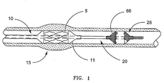
- deployment of balloon expandable stent 5 is accomplished by threading catheter 10 through the vascular system of the patient until stent 5 is located within a stenosis at predetermined treatment site 15. Once positioned, balloon 11 of catheter 10 is inflated to expand stent 5 against the vascular wall to maintain the opening. Stent deployment can be performed following treatments such as angioplasty, or during initial balloon dilation of the treatment site, which is referred to as primary stenting.
- Catheter 10 is typically guided to treatment site 15 by a guidewire.
- a guidewire In cases where the target stenosis is located in tortuous vessels that are remote from the vascular access point, such as coronary arteries 17 shown in FIG. 2, a steerable guidewire is commonly used.
- filter guidewire generally designated as 20 guides catheter 10 to treatment site 15 and includes distally disposed filter 25 to collect embolic debris that may be generated during the procedure.
- the invention is directed to manipulating various types of temporary filters wherein relative movement of the filter ends either causes or accompanies transformation of the filter between a collapsed configuration and a deployed configuration. Such transformation may be impelled by external mechanical means or by self-shaping memory (either self-expanding or self-collapsing) within the filter.
- filter 25 is self-expanding, meaning that filter 25 has a mechanical memory to return to the expanded, or deployed configuration.
- Such mechanical memory can be imparted to the metal comprising filter 25 by thermal treatment to achieve a spring temper in stainless steel, for example, or to set a shape memory in a susceptible metal alloy such as nitinol.
- Filter 25 preferably comprises a tube formed by braided filaments that define pores and have at least one inlet opening 66 that is substantially larger than the pores.
- filters may be used in filter 25, such as filter assemblies that include a porous mesh mounted to expandable struts.
- At least one of the filaments may be a wire having enhanced radiopacity compared to conventional non-radiopaque wires suitable for braiding filter 25.
- At least the majority of braiding wires forming filter 25 should be capable of being heat set into the desired filter shape, and such wires should also have sufficient elastic properties to provide the desired self-expanding or self-collapsing features.
- Stainless steel, and preferably nitinol monofilaments are suitable for braiding filter 25.
- a braiding wire having enhanced radiopacity may be made of, or coated with, a radiopaque metal such as gold, platinum, tungsten, alloys thereof, or other biocompatible metals having a relatively high X-ray attenuation coefficient compared with stainless steel or nitinol.
- a radiopaque metal such as gold, platinum, tungsten, alloys thereof, or other biocompatible metals having a relatively high X-ray attenuation coefficient compared with stainless steel or nitinol.
- One or more filaments having enhanced radiopacity may be inter-woven with non-radiopaque wires, or all wires comprising filter 25 may have the same enhanced radiopacity.
- one or more of the braid filaments may comprise composite wire 24, having radiopaque core 26 and non-radiopaque layer or casing 28.
- Such coaxial, composite wires are referred to as DFT (drawn-filled-tube) wires in the metallic arts, and are formed by inserting a solid billet of one metal into a hollow billet of a different metal, then repeatedly drawing and annealing the combination until a wire of desired diameter and hardness is achieved.
- a preferred DFT wire for use in the instant invention comprises a core of a 90% platinum-10% nickel alloy, and a casing of binary nickel-titanium (nitinol) alloy.
- the nitinol outer layer is able to provide the resulting wire with nearly undiminished mechanical properties.
- placing a radiopaque coating or layer around a nitinol core substantially effects the physical properties of the wire.
- PtNi core/nitinol tube DFT wire has a greater X-ray attenuation coefficient and nearly identical mechanical properties.
- Wire 24, comprising a PtNi core/nitinol tube combination, provides improved radiopacity of filter 25 without giving up the shape-memory or pseudo-elastic properties of nitinol, which contribute to good shape-retention and the elastic transformation of filter 25 between collapsed and deployed configurations.
- core 26 makes up at least approximately 25% of the total cross-section of wire 24, by area.
- wire 24 is preferably about 0.001 - 0.003 inch (0.03 - 0.08 mm) diameter, more preferably about 0.002 inch (0.05 mm) diameter.
- Such wires are available from Fort Wayne Metals Corp., Fort Wayne, Indiana, U.S.A..
- sheathless vascular filter devices are operated by a "push-pull" mechanism that is also typical of other expandable braid devices, as shown in FIGS. 3 and 4.
- Prior art expandable braid device 30 includes core wire 32 and tubular shaft 34 slidably disposed thereabout.
- Tubular braid 36 surrounds core wire 32 and has a braid distal end fixed to core wire distal end 40 and a braid proximal end fixed to shaft distal end 41.
- core wire 32 is pulled and shaft 34 is pushed, as shown by arrows 37 and 39 respectively in FIG. 4.
- the relative displacement of core wire 32 and shaft 34 moves the ends of braid 36 towards each other, forcing the middle region of braid 36 to expand.
- core wire 32 is pushed and shaft 34 is pulled, as shown by arrows 33 and 35 respectively in FIG. 3. This reverse manipulation draws the ends of braid 36 apart, pulling the middle region of braid 36 radially inward toward core wire 32.
- filter guidewire 20 includes core wire 42 and flexible tubular tip member 43, which is preferably a coil spring, fixed around the distal end of core wire 42.
- Thin wires made from stainless steel and/or one of various alloys of platinum are commonly used to make such coil springs for use in guidewires.
- Core wire 42 can be made from shape memory metal, such as nitinol, or preferably is a stainless steel wire tapered at the distal end. For treating small caliber vessels such as coronary arteries, core wire 42 will preferably measure about 0.006 inch (0.15 mm) in diameter.
- Tubular shaft 44 is slidably disposed around core wire 42, and includes relatively stiff proximal portion 46 and relatively flexible distal portion 48.
- Proximal portion 46 is preferably made from thin walled stainless steel tubing, usually referred to as hypotubing, although other metals can be used.
- Various metals or polymers can be used to make relatively flexible distal portion 48, although it is preferably made from thermoset polyimide tubing, available from sources such as HV Technologies, Inc., Trenton, GA, U.S.A..
- the length of distal portion 48 may be selected as appropriate for the intended use of the filter guidewire.
- portion 48 may be designed and intended to be flexible enough to negotiate tortuous coronary arteries, in which case the length of portion 48 may be 15 - 35 cm (5.9 - 13.8 inches), preferably at least approximately 25 cm (9.8 inches).
- adaptations of the invention for treatment of renal arteries may require a relatively shorter flexible portion 48, and versions intended for approaching vessels in the head and neck may require a relatively longer flexible portion 48.
- shaft 44 may have an outer diameter of about 0.014 inch (0.36 mm).
- the general uniformity of the outer diameter is preferably maintained by connecting proximal portion 46 and distal portion 48 with lap joint 49.
- Lap joint 49 uses any suitable adhesive, preferably cyanoacrylate instant adhesives from Loctite Corporation, Rocky Hill, CT, U.S.A., or Dymax Corporation, Torrington, CT, U.S.A..
- Lap joint 49 can be formed by any conventional method such as reducing the wall thickness of proximal portion 46 in the region of joint 49, or by forming a step-down in diameter at this location with negligible change in wall thickness, as by swaging.
- Expandable tubular filter 25 is positioned concentrically with core wire 42, and is sized such that when it is fully deployed, as shown in FIGS. 1 and 2, the outer perimeter of filter 25 will contact the inner surface of the vessel wall. The surface contact is preferably maintained around the entire vessel lumen to prevent any emboli from slipping past filter 25.
- cyanoacrylate adhesive is used to secure filter distal end 27 to tip member 43, and to secure filter proximal end 29 near the distal end of shaft 44.
- radiopaque marker bands (not shown), such as platinum rings, can be incorporated into the adhesive joints securing filter ends 27, 29 respectively to tip member 43 and shaft 44.
- Filter 25 is deployed by advancing, or pushing shaft 44 relative to core wire 42 such that filter distal and proximal ends 27, 29 are drawn toward each other, forcing the middle, or central section of filter 25 to expand radially.
- Filter 25 is collapsed by withdrawing, or pulling shaft 44 relative to core wire 42 such that filter distal and proximal ends 27, 29 are drawn apart from each other, forcing the middle, or central section of filter 25 to contract radially.
- Transition sleeve 45 is fixed about core wire 42 and is slidably located within the distal end of flexible distal portion 48 of tubular shaft 44.
- Transition sleeve 45 is preferably made of polyimide tubing similar to that used in distal portion 48 and extends distally therefrom.
- sleeve 45 supports core wire 42 and provides a gradual transition in overall stiffness of filter guidewire 20 adjacent the distal end of shaft 44.
- Transition sleeve 45 is fixed to core wire 42, preferably with cyanoacrylate adhesive, such that relative displacement between shaft 44 and core wire 42 causes corresponding relative displacement between shaft 44 and sleeve 45.
- filter guidewire 20 provides the functions of a temporary filter combined with the performance of a steerable guidewire.
- FIG. 6 depicts a second embodiment of the invention in which filter guidewire 51 incorporates a typical steerable guidewire 55 and deploys a self-expanding filter.
- Guidewire 55 comprises core wire 52, including a tapered distal end, and flexible tubular tip member 54, which is preferably a coiled spring, fixed there around. At least a distal portion of tip member 54 is preferably made from radiopaque metal wire, such as an alloy of platinum.
- Self-expanding filter 25 is mounted about guidewire 55, with filter distal and proximal ends 27, 29 being mounted slidably there along and, optionally, being fitted with radiopaque markers (not shown). Filter proximal end 29 is attached to actuator 63 using adhesive or solder.
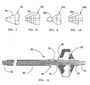
- Actuator 63 is mounted slidably about guidewire 55 and is preferably made of shape memory metal, such as nitinol. Actuator 63 is illustrated in FIG. 7, with alternative actuators 163, 263 and 363 depicted in FIGS. 8, 9 and 10, respectively. In actuator 163, a series of ridges having increasing diameters presents tapered surface 164 for step-wise engagement with rod distal end 82. Actuator 263 provides a single ridge 264 for engagement with rod distal end 82. Rod distal end 82 can be formed with a complementary recess (not shown) to mate with ridge 264 for a snap-fit type engagement therewith.
- a series of barbs having increasing diameters presents tapered surface 364 for step-wise engagement with rod distal end 82.
- a variety of other designs for mating components can be applied to the invention to detachably join rod distal end 82 and actuator 63. Examples include male and female screw threads, hook and loop elements common in the field of textiles, or numerous mechanisms intended to temporarily join extension wires to guidewires, examples of which are shown in U.S. Patent No. 4,827,941 (Taylor), U.S. Patent No. 5,113,872 (J strig pen et al. ) and U.S. Patent No. 5,133,364 (Palermo et al .).
- Stop element 77 is preferably a polyimide tube or ring that is fixed about guidewire 55 at a location between filter distal end 27 and filter proximal end 29.
- This embodiment may include assist spring 95, which is preferably a coiled tension spring mounted around guidewire 55 inside filter 25, and having distal and proximal ends fixed to filter distal and proximal ends 27, 29, respectively.
- Spring 95 can assist in the deployment of filter 25 by providing tension between filter distal and proximal ends 27, 29.
- Spring 95 can be mounted around stop element 77, or spring 95 may have some turns of the coil attached directly to guidewire 55 such that spring 95 can replace stop element 77.
- Elongate hollow rod 80 is slidably and removably disposed along guidewire 55 such that rod distal end 82 is engageable with actuator 63, as shown in the alternate position in FIG. 6.
- Rod 80 can be made from metal such as stainless steel or nitinol, or preferably from a rigid polymer such as polyimide.
- FIG. 11 illustrates a third embodiment of the invention in which filter guidewire 50 also incorporates steerable guidewire 55, as described above with respect to filter guidewire 51.
- filter guidewire 50 the mounting arrangement of filter 25 is reversed with respect to filter guidewire 20, such that filter distal end 27 is slidably mounted around and adjacent to the distal end of guidewire 55, and filter proximal end 29 is fixed to guidewire 55.
- Elongate tubular actuator 60 is slidingly and coaxially disposed around guidewire 55 proximal to filter 25.
- Link 65 movably extends through opening 66 in filter 25 adjacent filter proximal end 29 and connects the distal end of actuator 60 to filter distal end 27.
- Opening 66 is one of the inlet openings of filter 25, however any opening large enough to slidably pass link 65 will suffice.
- a standard or over-sized pore in filter 25 may permit link 65 to extend therethrough.
- Actuator 60 can be made from thin walled metal tubing, such as stainless steel hypodermic tubing, or more preferably, polyimide tubing.
- actuator 60 should have an outside diameter of 0.014 inch (0.36 mm) or less so that filter guidewire 50 can be slidably received within the guidewire lumen of the catheter.
- Link 65 is preferably a thin wire, such as stainless steel, measuring approximately 0.002 to 0.008 inch (0.05 to 0.20 mm) in diameter, most preferably 0.006 inch (0.15 mm).
- link 65 may be a non-metallic filament capable of pushing and/or pulling filter distal end 27.
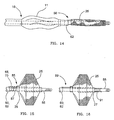
- Transformation of filter 25 from the deployed configuration to the collapsed configuration, shown in FIG. 14, is achieved by manipulating the proximal ends of guidewire 55 and actuator 60 as follows. Pushing actuator 60 distally while pulling guidewire 55 proximally causes link 65 to advance into filter 25 and displace filter distal end 27 distally along guidewire 55. The movement of filter distal end 27 away from filter proximal end 29, which is fixed to guidewire 55, forces filter 25 to collapse around guidewire 55 to a lower profile that is suitable for introduction to or withdrawal from the patient. The distal end of actuator 60 is spaced proximally from filter proximal end 29 a distance sufficient to permit a range of motion of actuator 60 without contacting filter proximal end 29. In this first version of the third embodiment of the invention, wherein filter 25 is self-expanding, link 65 is placed under compression loading to collapse filter 25, and thus link 65 is also referred to as a push rod.
- filter 25 may be self-collapsing, wherein its shape memory is to return to the collapsed configuration.
- deployment of filter 25 is achieved and maintained by pulling actuator 60 proximally while pushing guidewire 55 distally, which action draws filter distal end 27 and filter proximal end 29 towards each other and forces expansion of filter 25.
- link 65 is placed under tension loading to deploy filter 25.
- FIG. 12 depicts filter guidewire 56, which is a preferred fourth embodiment of the invention, and wherein self-expanding filter 25 is arranged over guidewire 55 similarly to filter guidewire 50, described above.
- actuator 62 is a short ring slidingly and coaxially disposed around guidewire 55 proximal to filter 25.
- Link 70 movably extends through opening 78 within filter proximal end 29 and connects actuator 62 to filter distal end 27.
- Link 70 includes link proximal segment 72 and link distal segment 74.
- Link distal segment 74 is a tubular element that is fixed to filter distal end 27 and is slidingly disposed around guidewire 55 within filter 25.
- Link distal segment 74 is made from thin walled tubing, preferably polyimide.
- Link proximal segment 72 is comparable to the wire of link 65, and extends from an attachment point on actuator 62 into filter 25 to connect with link distal segment 74.
- Joint 76 attaches filter proximal end 29 to guidewire 55, and includes opening 78, which guides link proximal segment 72 that is slidably disposed therethrough.
- Joint 76 may be made from any suitable fastening material such as adhesive, braze alloy, or preferably, solder.
- opening 78 is formed by a short section of thin walled polyimide tubing (not shown), which is incorporated into joint 76 within filter proximal end 29.
- opening 78 can be formed by including a removable mandrel, such as a stainless steel wire coated with polytetrafluoroethylene (PTFE), in joint 76 during its formation.
- PTFE polytetrafluoroethylene
- Elongate hollow rod 180 is slidably and removably disposed along guidewire 55 such that rod distal end 182 is engageable with actuator 62.
- Rod distal end 182 is an over-sized section of rod 180 such that it will slidably fit over at least a proximal portion of actuator 62, as shown in the alternate position in FIG. 12.
- the engaged combination of rod 180 and actuator 62 can apply distally directed force to link 70, similarly to the operation of elongate actuator 60 in guidewire filter 50.
- pushing rod 180 distally while pulling guidewire 55 proximally causes link 70 to advance into filter 25 and translate filter distal end 27 along guidewire 55 in a distal direction.
- filter distal end 27 forces filter 25 to collapse around guidewire 55 to a lower profile for introduction to or withdrawal from the patient.
- Actuator 62 is spaced proximally from filter proximal end 29 a distance sufficient to permit a range of motion of actuator 62 without contacting filter proximal end 29.
- rod distal end 182 can be an unexpanded end of rod 180, similar to rod distal end 82 of rod 80, in which case rod distal end 182 may simply abut actuator 62 without extending thereover.
- Optional stop 79 may be fixed to guidewire 55 proximal to actuator 62. Stop 79 can prevent interventional catheters positioned on guidewire 55 from engaging and moving actuator 62 and unintentionally collapsing filter 25. Stop 79 is smaller in diameter than actuator 62 such that rod 180 may be sized to slide over stop 79 and engage actuator 62, as shown in the alternate position in FIG. 12.
- filter guidewire 56 There are advantages to filter guidewire 56, besides the more habitual "reverse" push-pull action that it shares with filter guidewire 50, described above.
- guidewire 55 In filter guidewire 50, guidewire 55 must be small enough to fit slidably inside of actuator 60 which, in turn, must fit inside the guidewire lumen of a therapeutic catheter.
- guidewire 55 In filter guidewire 56, guidewire 55 can be large enough to fill the guidewire lumen of the same sized therapeutic catheter, because elongate rod 180 can be removed and replaced with the catheter.
- a larger, more standard sized guidewire can be included in the filter device, with the attendant performance advantages that accompany such an increase in size.
- FIGS. 6 and 12 it may be desirable to use a catheter, such as catheter 10, to operate actuators 63, 62 of guidewire filters 51, 56 respectively, to collapse self-expanding filter 25.
- catheter 10 replaces rods 80, 180 in all respects, and no exchange is required therebetween.
- FIG. 13 shows catheter 10 placed over filter guidewire 56, with optional stop 79 omitted therefrom.
- FIG. 14 shows the same arrangement as FIG. 13, with catheter 10 being advanced to operate actuator 62, causing filter 25 to collapse.
- balloon 11 of catheter 10 would typically be deflated while catheter 10 is used to collapse filter 25.
- FIG. 15 depicts filter guidewire 85, which is a modification of filter guidewires 50, 56, and is made by mounting proximal assist spring 87 around guidewire 55 between filter proximal end 29 and actuators 60, 62.
- a modification of filter guidewire 56, filter 25 is self-expanding, and spring 87 is a coiled compression spring that assists in the expansion of filter 25 by maintaining a separating force between filter proximal end 29 and actuator 62.
- Spring 87 can surround guidewire 55 only or, preferably, surround both guidewire 55 and link 65,70, as shown.
- filter 25 is self-collapsing, with spring 87 being a coiled tension spring attached at its ends to filter proximal end 29 and actuator 60.
- actuator 60 can apply proximally directed force to overcome the shape memory of filter 25 and the tension force in spring 87.
- FIG. 16 depicts filter guidewire 89, which is another modification to filter guidewires 50, 56, and is made by mounting assist spring 91 around guidewire 55 distal to filter 25.
- filter 25 is self-expanding, with spring 91being a coiled compression spring having a proximal end abutting filter distal end 27 and having a distal end fixed to guidewire 55.
- Spring 91 assists in the deployment of filter 25 by maintaining proximally directed force against filter distal end 27.
- filter 25 is self-collapsing, with spring 91 being a tension spring having a proximal end fixed to filter distal end 27 and having a distal end fixed to guidewire 55.
- actuator 60 can apply proximally directed force to overcome the shape memory of filter 25 and the tension force in spring 91.
- FIG. 17 depicts filter guidewire 93, which is another modification to filter guidewires 50, 56, and is made by mounting assist spring 95 around guidewire 55 and link distal segment 74 inside filter 25.
- filter 25 is self-expanding, with spring 95 being a coiled tension spring having a distal end attached to filter distal end 27 and having a proximal end attached to filter proximal end 29.
- Spring 95 assists in the deployment of filter 25 by maintaining tension between filter distal and proximal ends 27, 29.
- filter 25 is self-collapsing, with spring 95 being a coiled compression spring mounted between filter distal and proximal ends 27, 29.
- actuator 60 can apply proximally directed force to overcome the shape memory of filter 25 and the compression force in spring 95.
- All of the above-mentioned coiled assist springs can be fabricated with fine metal wire of about 0.001 to 0.005 inch (0.03 to 0.13 mm) diameter, preferably nitinol wire having 0.003 inch (0.08 mm) diameter.
- a removable handle device (not shown) of a type familiar to those of skill in the art may be used.
- Such handle devices can have telescoping shafts with collet-type clamps that grip respectively, core wire 42 and shaft 44 in filter guidewire 20, guidewire 55 and actuator 60 in filter guidewire 50, and guidewire 55 and rods 80, 180 in filter guidewires 51 and 56.
- the handle device can also serve as a steering handle, or "torquer" which is useful for rotating steerable-type guidewires that are incorporated in the instant invention.
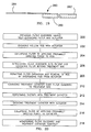
- filter guidewire 85 having self-expanding filter 25 and actuator 62, is provided (step 100), and filter 25 is collapsed by advancing hollow rod 80 against actuator 62 (step 102). With filter 25 in the collapsed configuration, filter guidewire 85 is advanced into the patient's vasculature until filter 25 is beyond the intended treatment site (step 104). Withdrawal of rod 80 allows filter 25 to expand under the combination of its own shape memory and the compression force of proximal spring 87 (step 106).
- a therapeutic catheter is advanced over filter guidewire 85 to the intended treatment site (step 108), and the therapy, such as balloon angioplasty, is performed (step 110). Any embolic debris generated during the therapy is captured in filter 25.
- the therapeutic catheter is prepared for withdrawal, as by deflating the balloon, if so equipped, and the catheter is advanced against actuator 62 to cause filter 25 to collapse (step 112).
- the catheter is used to continuously apply distally directed force against actuator 62 to maintain filter 25 in its collapsed configuration, filter guidewire 85 and the therapeutic catheter can be withdrawn together (step 114).
- rod 80 is first advanced over guidewire 55 until it engages actuator 63 (step 202). Pulling guidewire 55 proximally while pushing rod 80 distally against actuator 63 forces actuator 63 to slide distally until it is restrained by stop element 77. With actuator 63 thus restrained, rod 80 can attain a secure, albeit temporary, engagement with actuator 63 by wedging rod distal end 82 onto proximal taper 64 of actuator 63. To collapse filter 25, forces are applied to separate filter distal and proximal ends 27, 29. Proximally directed force is applied to filter proximal end 29 by pulling the engaged combination of rod 80 and actuator 63 proximally.
- distally directed force is applied to filter distal end 27 by pushing guidewire 55 distally, which advances stop element 77 into contact with filter distal end 27.
- Applying a first degree of proximally directed force to rod 80 will cause filter 25 to collapse (step 204), such that filter guidewire 51 can be introduced into the patient and directed to the desired treatment site (step 206).
- FIG. 19 depicts a rapidly exchangeable rod 280 for use with filter guidewires 51, 56.
- Rod 280 includes proximal shaft 284, and distal section 286, which is essentially a short portion of rods 80, 180.
- Distal section 286 is only about 10 - 30 cm (3.9 - 11.8 inches) long, making it easy to exchange over the portion of filter guidewire 51, 56 that extends outside of the patient, as is understood by those of skill in the field of intravascular catheters.
- Proximal shaft 284 preferably is a wire having a minimum diameter of about 0.012 inch (0.30 mm), and is tapered and attached to distal section 286.
- the stiffness of proximal shaft 284, and the secure attachment thereof to distal section 286 provide a rapidly exchangeable alternative to rods 80, 180 for pushing or pulling actions, as may be required.
- catheter 10 can also be of the rapid exchange type to facilitate interchanging rods and catheters.
- the invention has been particularly shown and described with reference to the preferred embodiments thereof, it will be understood by those skilled in the art that various changes in form and detail may be made therein without departing from the spirit and scope of the invention.
- the invention may be used in any intravascular treatment utilizing a guidewire where the possibility of loosening emboli may occur.
- the description herein illustrates angioplasty and stent placement procedures as significant applications, it should be understood that the present invention is in no way limited to those environments.
Landscapes
- Health & Medical Sciences (AREA)
- Life Sciences & Earth Sciences (AREA)
- Public Health (AREA)
- Transplantation (AREA)
- Engineering & Computer Science (AREA)
- Biomedical Technology (AREA)
- Heart & Thoracic Surgery (AREA)
- Vascular Medicine (AREA)
- Cardiology (AREA)
- Oral & Maxillofacial Surgery (AREA)
- Animal Behavior & Ethology (AREA)
- General Health & Medical Sciences (AREA)
- Veterinary Medicine (AREA)
- Surgical Instruments (AREA)
- Media Introduction/Drainage Providing Device (AREA)
- Eye Examination Apparatus (AREA)
- Fats And Perfumes (AREA)
- Control Of Motors That Do Not Use Commutators (AREA)
- Filtering Materials (AREA)
Abstract
Description
Claims (44)
- A filter guidewire for capturing embolic material generated during treatment of a lesion in vessels of a patient, the guidewire comprising:an elongate core wire having a proximal end and a tapered distal end;a flexible tubular tip member fixed adjacent the core wire distal end;an elongate tubular shaft slidably disposed along the core wire, the shaft including an elongate proximal portion and a relatively short distal portion, the distal portion being more flexible than the proximal portion and being disposed proximally of the tip member;a transition sleeve fixed about the core wire, the sleeve being slidably disposed within the shaft distal portion and extending distally therefrom; anda generally tubular filter mounted coaxially about the core wire, the filter having a tapered distal end fixed to the tip member and a tapered proximal end fixed to the shaft distal portion, wherein relative displacement of the filter ends associated with longitudinal displacement between the tubular shaft and the core wire causes transformation of the filter between a collapsed configuration and a deployed configuration.
- The filter guidewire of claim 1 wherein the tubular shaft proximal portion comprises metal tubing.
- The filter guidewire of claim 1 wherein the tubular shaft distal portion comprises polymeric tubing.
- The filter guidewire of claim 1 wherein the transition sleeve comprises polymeric tubing.
- The filter guidewire of claim 3 wherein the polymeric tubing comprises polyimide.
- The filter guidewire of claim 4 wherein the polymeric tubing comprises polyimide.
- A temporary filter guidewire comprising:an elongate flexible guidewire wire having a proximal end and a flexible tubular element fixed about a guidewire distal region;a generally tubular, self-expanding filter mounted coaxially about the guidewire, the filter having distal and proximal tapered ends slidingly disposed about the guidewire distal region, wherein relative separation of the filter ends causes transformation of the filter from a deployed configuration to a collapsed configuration;a stop element fixed to the guidewire between the filter distal and proximal ends, the stop element obstructing movement of the filter distal and proximal ends along the guidewire;a tubular actuator fixed to the filter proximal end and extending proximally adjacent thereto, the tubular actuator slidably disposed along the guidewire; andan elongate hollow rod slidably and removably disposed about the guidewire and having a rod distal end releasably engageable with the tubular actuator the hollow rod being operable, when the rod distal end is so engaged and in response to applying a first degree of proximally directed force to the hollow rod, to withdraw the filter until the filter distal end contacts the stop element and to further withdraw the filter proximal end to separate the filter distal and proximal ends, to cause the filter to transform from the deployed configuration to the collapsed configuration.
- The temporary filter guidewire of claim 7 wherein the hollow rod is further operable, in response to applying a second, higher degree of proximally directed force to the rod, to disengage the hollow rod from the tubular actuator, such that the hollow rod can be removed from the guidewire and the filter can be free to expand itself.
- The temporary filter guidewire of claim 7 wherein the hollow rod is operable to engage the rod distal end with the tubular actuator by compression of the tubular actuator between the rod distal end and the stop element.
- The temporary filter guidewire of claim 9 wherein compression of the tubular actuator between the rod distal end and the stop element causes frictional engagement between the rod distal end and a tapered proximal end of the tubular actuator.
- The temporary filter guidewire of claim 7 wherein the stop element comprises a tube.
- The temporary filter guidewire of claim 7 wherein the stop element comprises a coiled spring having at least one turn fixed to the guidewire.
- The temporary filter guidewire of claim 11 further comprising a coiled tension spring mounted about the stop element and the guidewire, the spring having distal and proximal ends fixed to the filter distal and proximal ends, respectively.
- The temporary filter guidewire of claim 7 wherein the hollow rod comprises an elongate, wire-like proximal shaft and a relatively short tubular distal section.
- The temporary filter guidewire of claim 7 wherein the self-expanding filter comprises braided multiple filaments.
- The temporary filter guidewire of claim 15 wherein at least one of the braided filaments comprises a radiopaque material.
- The temporary filter guidewire of claim 15 wherein at least one of the braided filaments comprises a wire having an inner core of a first material surrounded by an outer layer of a second material.
- The temporary filter guidewire of claim 17 wherein one of the first and second materials is radiopaque and the other of the first and second materials is relatively non-radiopaque.
- The temporary filter guidewire of claim 18 wherein the wire is formed by a drawn-filled-tube process.
- The temporary filter guidewire of claim 19 wherein the first material is an alloy comprising 90% platinum and 10% nickel, and wherein the second material is nitinol.
- A temporary filter device comprising:an elongate flexible guidewire having a proximal end and a flexible tubular element fixed about a guidewire distal region;a generally tubular filter mounted coaxially about the guidewire, the filter having a tapered distal end slidingly disposed about the guidewire distal region and a tapered proximal end fixed about the guidewire, the filter including an opening near the filter proximal end, wherein relative longitudinal movement between the filter ends accompanies transformation of the filter between a collapsed configuration and a deployed configuration;a tubular actuator slidably disposed along the guidewire, the actuator including a proximal end and a distal end disposed proximally of the filter; anda link slidably disposed through the opening and connecting the actuator distal end to the filter distal end.
- The temporary filter device of claim 21 wherein the proximal end of the filter is fixed about the guidewire by a joint having the opening therethrough.
- The temporary filter device of claim 21 wherein the link includes a tubular distal segment slidably disposed along the guidewire, the distal segment being disposed within the filter.
- The temporary filter device of claim 21 wherein the tubular actuator is an elongate tube.
- The temporary filter device of claim 21 wherein the tubular actuator is a relatively short tube or ring.
- The temporary filter device of claim 25 further comprising an elongate hollow rod slidably and removably disposed along the guidewire, the rod having a distal end engageable with the tubular actuator.
- The temporary filter device of claim 26 further comprising a stop element fixed to the guidewire proximal to the tubular actuator, the stop element having a transverse dimension smaller than a transverse dimension of the tubular actuator such that the stop element is operable to permit the hollow rod to slide there over while being capable of preventing a catheter slidably mounted on the guidewire from engaging the tubular actuator.
- The temporary filter device of claim 26 wherein the hollow rod comprises an elongate, wire-like proximal shaft and a relatively short tubular distal section.
- The temporary filter device of claim 26 wherein the elongate hollow rod further comprises an interventional catheter.
- A temporary filter device comprising:an elongate flexible guidewire having a proximal end and a flexible tubular element fixed about a guidewire distal region;a braided tubular filter mounted coaxially about the guidewire, the filter having a tapered distal end slidingly disposed about the guidewire distal region and a tapered proximal end fixed about the guidewire, the filter including an opening near the filter proximal end, wherein relative longitudinal movement between the filter ends accompanies transformation of the filter between a collapsed configuration and a deployed configuration;a tubular actuator slidably disposed along the guidewire, the actuator including a proximal end and a distal end disposed proximally of the filter; anda link slidably disposed through the opening and connecting the actuator distal end to the filter distal end.
- The temporary filter device of claim 30 further comprising a coiled compression spring disposed around the guidewire between and abutting the filter proximal end and the actuator distal end to assist in transformation of the filter to the deployed configuration.
- The temporary filter device of claim 30 further comprising a coiled tension spring disposed around the guidewire, the tension spring attached between the filter proximal and distal ends to assist in transformation of the filter to the deployed configuration.
- The temporary filter device of claim 30 further comprising a coiled compression spring disposed around the guidewire, the compression spring having a spring distal end fixed to the guidewire about the guidewire distal region and a spring proximal end abutting the filter distal end to assist in transformation of the filter to the deployed configuration.
- The temporary filter device of claim 30 further comprising a coiled tension spring disposed around the guidewire, the tension spring attached between the filter proximal end and the actuator distal end to assist in transformation of the filter to the collapsed configuration.
- The temporary filter device of claim 30 further comprising a coiled compression spring disposed around the guidewire between and abutting the filter proximal and distal ends to assist in transformation of the filter to the collapsed configuration.
- The temporary filter device of claim 30 further comprising a coiled tension spring disposed around the guidewire, the tension spring having a spring distal end fixed to the guidewire about the guidewire distal region and a spring proximal end fixed to the filter distal end to assist in transformation of the filter to the collapsed configuration.
- A temporary filter device comprising:an elongate flexible guidewire having a proximal end, a distal end, and a flexible tubular element fixed about a guidewire distal region;a generally tubular filter mounted coaxially about the guidewire, the filter having a tapered distal end slidingly disposed near the distal end of the guidewire and a tapered proximal end fixed to the guidewire, the filter including an opening adjacent the filter proximal end;an actuator mechanism slidably disposed about the guidewire and extending slidably through the opening to connect with the filter distal end, wherein proximal displacement of the guidewire relative to the actuator mechanism separates the filter proximal and distal ends, causing transformation of the filter from a deployed configuration to a collapsed configuration.
- A temporary filter system comprising:an elongate flexible guidewire having a proximal end, a distal end, and a flexible tubular element fixed about a guidewire distal region;a generally tubular, self-deploying filter mounted coaxially about the guidewire, the filter having a tapered distal end slidingly disposed near the distal end of the guidewire and a tapered proximal end fixed to the guidewire, the filter including an opening adjacent the filter proximal end, wherein relative displacement between the filter ends causes transformation of the filter between a collapsed configuration and a deployed configuration;an actuator ring slidably disposed along the guidewire proximally of the filter;a link slidably disposed through the opening and connecting the actuator ring to the filter distal end; andan interventional catheter slidably disposed along the guidewire, the catheter having a distal end capable of engaging with and displacing the actuator ring, causing transformation of the filter from a deployed configuration to a collapsed configuration
- A temporary intraluminal filter having a generally cylindrical body with tapered ends, the filter comprising a tube formed by braided filaments that define pores, the filter having at least one inlet opening that is substantially larger than the pores, wherein relative longitudinal movement between the filter ends accompanies transformation of the filter between a collapsed configuration and a deployed configuration, and wherein at least one of the braided filaments comprises a radiopaque material.
- The filter of claim 39 wherein the at least one of the braided filaments comprising a radiopaque material is a wire having an inner core of a first material surrounded by an outer layer of a second material, and wherein one of the first and second materials is radiopaque and the other of the first and second materials is relatively non-radiopaque.
- The filter guidewire of claim 40 wherein the wire is formed by a drawn-filled-tube process.
- The filter guidewire of claim 40 wherein the first material is an alloy comprising 90% platinum and 10% nickel, and wherein the second material is nitinol.
- A method of capturing embolic material generated during a vascular intervention at a treatment site within a patient, the method including the steps of:providing a filter guidewire including a guidewire and a self-expanding filter assembly having a tapered filter distal end slidingly disposed adjacent a guidewire distal end and a tapered filter proximal end fixed to the guidewire, the filter guidewire further including an actuator mechanism slidably disposed along the guidewire proximal to the filter and connected to the filter distal end;collapsing the filter assembly by advancing a hollow rod distally along the guidewire until the rod engages with and distally displaces the actuator mechanism;introducing the filter guidewire into and through the patient's vasculature until the filter assembly is located downstream of the treatment site;allowing the filter assembly to expand by withdrawing the rod from engagement with the actuator mechanism and removing the rod from the patient;advancing a treatment catheter over the guidewire to position the catheter within the treatment site;performing the vascular intervention with the treatment catheter and capturing embolic material that may be generated thereby;collapsing the filter assembly by advancing the treatment catheter distally along the filter guidewire until the catheter engages with and distally displaces the actuator mechanism;withdrawing the filter guidewire and the catheter together while maintaining distal displacement of the actuator mechanism.
- A method of capturing embolic material generated during a vascular intervention at a treatment site within a patient, the method including the steps of:providing a filter guidewire including a guidewire and a self-expanding filter assembly having filter distal and proximal tapered ends slidingly disposed adjacent a guidewire distal end, the filter guidewire further including an actuator slidably mounted about the guidewire and fixed to the filter proximal end, and a stop element fixed to the guidewire between the filter distal and proximal ends;engaging a rod distal end with the actuator by compressing the actuator between an elongate hollow rod and the stop element;collapsing the filter assembly by applying a first degree of proximally directed force to the rod and simultaneously applying an equal degree of distally directed force to the guidewire;introducing the filter guidewire into and through the patient's vasculature until the filter assembly is located downstream of the treatment site;permitting self-expansion of the filter and removal of the rod from the filter guidewire by applying a second, higher degree of proximally directed force to the rod and simultaneously applying an equal degree of distally directed force to the guidewire to disengage the rod from the actuator;advancing a treatment catheter over the guidewire to position the catheter within the treatment site;performing the vascular intervention with the treatment catheter;engaging the actuator with a distal end of the catheter by compressing the actuator between the treatment catheter and the stop element;collapsing the filter assembly by applying the first degree of proximally directed force to the catheter and simultaneously applying an equal degree of distally directed force to the guidewire;withdrawing the filter guidewire and catheter together from the patient.
Priority Applications (2)
| Application Number | Priority Date | Filing Date | Title |
|---|---|---|---|
| EP03016923A EP1369096B1 (en) | 2001-04-03 | 2002-02-21 | Temporary intraluminal filter |
| EP03016924A EP1371344B1 (en) | 2001-04-03 | 2002-02-21 | Temporary intraluminal filter device |
Applications Claiming Priority (2)
| Application Number | Priority Date | Filing Date | Title |
|---|---|---|---|
| US824832 | 2001-04-03 | ||
| US09/824,832 US6866677B2 (en) | 2001-04-03 | 2001-04-03 | Temporary intraluminal filter guidewire and methods of use |
Related Child Applications (2)
| Application Number | Title | Priority Date | Filing Date |
|---|---|---|---|
| EP03016923A Division EP1369096B1 (en) | 2001-04-03 | 2002-02-21 | Temporary intraluminal filter |
| EP03016924A Division EP1371344B1 (en) | 2001-04-03 | 2002-02-21 | Temporary intraluminal filter device |
Publications (3)
| Publication Number | Publication Date |
|---|---|
| EP1247500A2 true EP1247500A2 (en) | 2002-10-09 |
| EP1247500A3 EP1247500A3 (en) | 2003-12-10 |
| EP1247500B1 EP1247500B1 (en) | 2005-07-20 |
Family
ID=25242438
Family Applications (3)
| Application Number | Title | Priority Date | Filing Date |
|---|---|---|---|
| EP02003917A Expired - Lifetime EP1247500B1 (en) | 2001-04-03 | 2002-02-21 | Temporary intraluminal filter guidewire and methods of use |
| EP03016924A Expired - Lifetime EP1371344B1 (en) | 2001-04-03 | 2002-02-21 | Temporary intraluminal filter device |
| EP03016923A Expired - Lifetime EP1369096B1 (en) | 2001-04-03 | 2002-02-21 | Temporary intraluminal filter |
Family Applications After (2)
| Application Number | Title | Priority Date | Filing Date |
|---|---|---|---|
| EP03016924A Expired - Lifetime EP1371344B1 (en) | 2001-04-03 | 2002-02-21 | Temporary intraluminal filter device |
| EP03016923A Expired - Lifetime EP1369096B1 (en) | 2001-04-03 | 2002-02-21 | Temporary intraluminal filter |
Country Status (5)
| Country | Link |
|---|---|
| US (2) | US6866677B2 (en) |
| EP (3) | EP1247500B1 (en) |
| JP (1) | JP2002336261A (en) |
| AT (3) | ATE299680T1 (en) |
| DE (3) | DE60221108T2 (en) |
Cited By (8)
| Publication number | Priority date | Publication date | Assignee | Title |
|---|---|---|---|---|
| WO2003094791A3 (en) * | 2002-05-06 | 2004-03-18 | Scimed Life Systems Inc | Inverted embolic protection filter |
| WO2003088869A3 (en) * | 2002-04-19 | 2004-03-25 | Salviac Ltd | A medical device |
| US6773448B2 (en) | 2002-03-08 | 2004-08-10 | Ev3 Inc. | Distal protection devices having controllable wire motion |
| US7232452B2 (en) | 2002-07-12 | 2007-06-19 | Ev3 Inc. | Device to create proximal stasis |
| EP1600107A4 (en) * | 2003-02-20 | 2015-11-18 | Kaneka Medix Corp | Wire device for medical use |
| CN105377184A (en) * | 2013-03-15 | 2016-03-02 | 微温森公司 | Embolic protection device |
| CN105813601A (en) * | 2013-11-28 | 2016-07-27 | 创新股份有限公司 | Filtration and entrapment apparatus and method of use |
| EP3730180A1 (en) * | 2009-04-21 | 2020-10-28 | Boston Scientific Scimed Inc. | Apparatus for advancing a device from one body lumen to another |
Families Citing this family (210)
| Publication number | Priority date | Publication date | Assignee | Title |
|---|---|---|---|---|
| EP0934092A4 (en) | 1997-03-06 | 2008-03-26 | Boston Scient Scimed Inc | DEVICE AND METHOD FOR DISTAL PROTECTION |
| IE980920A1 (en) | 1997-11-07 | 1999-05-19 | Salviac Ltd | An embolic protection device |
| US7491216B2 (en) | 1997-11-07 | 2009-02-17 | Salviac Limited | Filter element with retractable guidewire tip |
| US8002790B2 (en) | 1999-05-07 | 2011-08-23 | Salviac Limited | Support frame for an embolic protection device |
| AU3844499A (en) | 1999-05-07 | 2000-11-21 | Salviac Limited | Improved filter element for embolic protection device |
| US6918921B2 (en) | 1999-05-07 | 2005-07-19 | Salviac Limited | Support frame for an embolic protection device |
| US7799051B2 (en) | 1999-05-07 | 2010-09-21 | Salviac Limited | Support frame for an embolic protection device |
| US7014647B2 (en) | 1999-05-07 | 2006-03-21 | Salviac Limited | Support frame for an embolic protection device |
| US6964672B2 (en) | 1999-05-07 | 2005-11-15 | Salviac Limited | Support frame for an embolic protection device |
| US6402771B1 (en) | 1999-12-23 | 2002-06-11 | Guidant Endovascular Solutions | Snare |
| US6575997B1 (en) | 1999-12-23 | 2003-06-10 | Endovascular Technologies, Inc. | Embolic basket |
| US6660021B1 (en) | 1999-12-23 | 2003-12-09 | Advanced Cardiovascular Systems, Inc. | Intravascular device and system |
| US7918820B2 (en) | 1999-12-30 | 2011-04-05 | Advanced Cardiovascular Systems, Inc. | Device for, and method of, blocking emboli in vessels such as blood arteries |
| US6695813B1 (en) | 1999-12-30 | 2004-02-24 | Advanced Cardiovascular Systems, Inc. | Embolic protection devices |
| US6540722B1 (en) | 1999-12-30 | 2003-04-01 | Advanced Cardiovascular Systems, Inc. | Embolic protection devices |
| GB2369575A (en) | 2000-04-20 | 2002-06-05 | Salviac Ltd | An embolic protection system |
| US6964670B1 (en) | 2000-07-13 | 2005-11-15 | Advanced Cardiovascular Systems, Inc. | Embolic protection guide wire |
| US6537294B1 (en) | 2000-10-17 | 2003-03-25 | Advanced Cardiovascular Systems, Inc. | Delivery systems for embolic filter devices |
| US6893451B2 (en) | 2000-11-09 | 2005-05-17 | Advanced Cardiovascular Systems, Inc. | Apparatus for capturing objects beyond an operative site utilizing a capture device delivered on a medical guide wire |
| US6506203B1 (en) | 2000-12-19 | 2003-01-14 | Advanced Cardiovascular Systems, Inc. | Low profile sheathless embolic protection system |
| US7044952B2 (en) | 2001-06-06 | 2006-05-16 | Sdgi Holdings, Inc. | Dynamic multilock anterior cervical plate system having non-detachably fastened and moveable segments |
| US20020188314A1 (en) * | 2001-06-07 | 2002-12-12 | Microvena Corporation | Radiopaque distal embolic protection device |
| US6599307B1 (en) | 2001-06-29 | 2003-07-29 | Advanced Cardiovascular Systems, Inc. | Filter device for embolic protection systems |
| US7338510B2 (en) | 2001-06-29 | 2008-03-04 | Advanced Cardiovascular Systems, Inc. | Variable thickness embolic filtering devices and method of manufacturing the same |
| US6951570B2 (en) * | 2001-07-02 | 2005-10-04 | Rubicon Medical, Inc. | Methods, systems, and devices for deploying a filter from a filter device |
| US6962598B2 (en) * | 2001-07-02 | 2005-11-08 | Rubicon Medical, Inc. | Methods, systems, and devices for providing embolic protection |
| US6638294B1 (en) | 2001-08-30 | 2003-10-28 | Advanced Cardiovascular Systems, Inc. | Self furling umbrella frame for carotid filter |
| US6592606B2 (en) | 2001-08-31 | 2003-07-15 | Advanced Cardiovascular Systems, Inc. | Hinged short cage for an embolic protection device |
| US6878151B2 (en) * | 2001-09-27 | 2005-04-12 | Scimed Life Systems, Inc. | Medical retrieval device |
| US8262689B2 (en) | 2001-09-28 | 2012-09-11 | Advanced Cardiovascular Systems, Inc. | Embolic filtering devices |
| US20050021075A1 (en) * | 2002-12-30 | 2005-01-27 | Bonnette Michael J. | Guidewire having deployable sheathless protective filter |
| WO2003055413A2 (en) | 2001-12-21 | 2003-07-10 | Salviac Limited | A support frame for an embolic protection device |
| US7241304B2 (en) | 2001-12-21 | 2007-07-10 | Advanced Cardiovascular Systems, Inc. | Flexible and conformable embolic filtering devices |
| DE60315425T2 (en) | 2002-03-05 | 2008-06-26 | Salviac Ltd. | SYSTEM FOR PROTECTION FROM EMBOLICS |
| US6887258B2 (en) | 2002-06-26 | 2005-05-03 | Advanced Cardiovascular Systems, Inc. | Embolic filtering devices for bifurcated vessels |
| US7172614B2 (en) | 2002-06-27 | 2007-02-06 | Advanced Cardiovascular Systems, Inc. | Support structures for embolic filtering devices |
| US7479151B2 (en) * | 2002-08-05 | 2009-01-20 | Gardia Medical Ltd. | Embolism filter with self-deployable guidewire stop |
| US7252675B2 (en) | 2002-09-30 | 2007-08-07 | Advanced Cardiovascular, Inc. | Embolic filtering devices |
| US7331973B2 (en) | 2002-09-30 | 2008-02-19 | Avdanced Cardiovascular Systems, Inc. | Guide wire with embolic filtering attachment |
| US20040088000A1 (en) | 2002-10-31 | 2004-05-06 | Muller Paul F. | Single-wire expandable cages for embolic filtering devices |
| US7323001B2 (en) * | 2003-01-30 | 2008-01-29 | Ev3 Inc. | Embolic filters with controlled pore size |
| US8591540B2 (en) | 2003-02-27 | 2013-11-26 | Abbott Cardiovascular Systems Inc. | Embolic filtering devices |
| US20040193208A1 (en) * | 2003-03-27 | 2004-09-30 | Scimed Life Systems, Inc. | Radiopaque embolic protection filter membrane |
| US7597704B2 (en) * | 2003-04-28 | 2009-10-06 | Atritech, Inc. | Left atrial appendage occlusion device with active expansion |
| DE602004018059D1 (en) | 2003-04-30 | 2009-01-15 | Medtronic Vascular Inc | Perivascular repair system for leaks |
| US7892251B1 (en) | 2003-11-12 | 2011-02-22 | Advanced Cardiovascular Systems, Inc. | Component for delivering and locking a medical device to a guide wire |
| US7988705B2 (en) * | 2004-03-06 | 2011-08-02 | Lumen Biomedical, Inc. | Steerable device having a corewire within a tube and combination with a functional medical component |
| US7678129B1 (en) | 2004-03-19 | 2010-03-16 | Advanced Cardiovascular Systems, Inc. | Locking component for an embolic filter assembly |
| US8628564B2 (en) | 2004-05-25 | 2014-01-14 | Covidien Lp | Methods and apparatus for luminal stenting |
| AU2010236494B2 (en) | 2004-05-25 | 2013-05-30 | Covidien Lp | Vascular stenting for aneurysms |
| US8617234B2 (en) | 2004-05-25 | 2013-12-31 | Covidien Lp | Flexible vascular occluding device |
| EP1750619B1 (en) | 2004-05-25 | 2013-07-24 | Covidien LP | Flexible vascular occluding device |
| US20060206200A1 (en) | 2004-05-25 | 2006-09-14 | Chestnut Medical Technologies, Inc. | Flexible vascular occluding device |
| US8267985B2 (en) | 2005-05-25 | 2012-09-18 | Tyco Healthcare Group Lp | System and method for delivering and deploying an occluding device within a vessel |
| WO2006042114A1 (en) | 2004-10-06 | 2006-04-20 | Cook, Inc. | Emboli capturing device having a coil and method for capturing emboli |
| US9707071B2 (en) * | 2004-11-24 | 2017-07-18 | Contego Medical Llc | Percutaneous transluminal angioplasty device with integral embolic filter |
| US9510930B2 (en) * | 2008-10-22 | 2016-12-06 | Contego Medical, Llc | Angioplasty device with embolic filter |
| US8038696B2 (en) * | 2004-12-06 | 2011-10-18 | Boston Scientific Scimed, Inc. | Sheath for use with an embolic protection filter |
| US20060184194A1 (en) * | 2005-02-15 | 2006-08-17 | Cook Incorporated | Embolic protection device |
| US8221446B2 (en) | 2005-03-15 | 2012-07-17 | Cook Medical Technologies | Embolic protection device |
| US8945169B2 (en) | 2005-03-15 | 2015-02-03 | Cook Medical Technologies Llc | Embolic protection device |
| US9259305B2 (en) | 2005-03-31 | 2016-02-16 | Abbott Cardiovascular Systems Inc. | Guide wire locking mechanism for rapid exchange and other catheter systems |
| US20070233174A1 (en) * | 2005-04-01 | 2007-10-04 | Gordon Hocking | Trapping Filter for Blood Vessel |
| US9204819B2 (en) * | 2005-05-06 | 2015-12-08 | Vasonova, Inc. | Endovenous access and guidance system utilizing non-image based ultrasound |
| US20090118612A1 (en) | 2005-05-06 | 2009-05-07 | Sorin Grunwald | Apparatus and Method for Vascular Access |
| CN101180006B (en) | 2005-05-25 | 2010-09-22 | 切斯纳特医药技术公司 | System for delivering and deploying an occluding device within a vessel |
| US8273101B2 (en) | 2005-05-25 | 2012-09-25 | Tyco Healthcare Group Lp | System and method for delivering and deploying an occluding device within a vessel |
| US7850708B2 (en) | 2005-06-20 | 2010-12-14 | Cook Incorporated | Embolic protection device having a reticulated body with staggered struts |
| US8109962B2 (en) | 2005-06-20 | 2012-02-07 | Cook Medical Technologies Llc | Retrievable device having a reticulation portion with staggered struts |
| US7771452B2 (en) | 2005-07-12 | 2010-08-10 | Cook Incorporated | Embolic protection device with a filter bag that disengages from a basket |
| US7766934B2 (en) | 2005-07-12 | 2010-08-03 | Cook Incorporated | Embolic protection device with an integral basket and bag |
| US8187298B2 (en) | 2005-08-04 | 2012-05-29 | Cook Medical Technologies Llc | Embolic protection device having inflatable frame |
| US8377092B2 (en) | 2005-09-16 | 2013-02-19 | Cook Medical Technologies Llc | Embolic protection device |
| US20070073332A1 (en) * | 2005-09-26 | 2007-03-29 | Medtronic Vascular, Inc. | Intraluminal filter having a cover sleeve |
| US8632562B2 (en) | 2005-10-03 | 2014-01-21 | Cook Medical Technologies Llc | Embolic protection device |
| US8182508B2 (en) | 2005-10-04 | 2012-05-22 | Cook Medical Technologies Llc | Embolic protection device |
| US7811251B2 (en) * | 2005-10-13 | 2010-10-12 | Tyco Healthcare Group Lp | Trocar anchor |
| US8252017B2 (en) | 2005-10-18 | 2012-08-28 | Cook Medical Technologies Llc | Invertible filter for embolic protection |
| US8216269B2 (en) | 2005-11-02 | 2012-07-10 | Cook Medical Technologies Llc | Embolic protection device having reduced profile |
| US20070112371A1 (en) * | 2005-11-14 | 2007-05-17 | Medtronic Vascular, Inc. | Embolic protection filter having compact collapsed dimensions and method of making same |
| US8152831B2 (en) | 2005-11-17 | 2012-04-10 | Cook Medical Technologies Llc | Foam embolic protection device |
| US20070135826A1 (en) * | 2005-12-01 | 2007-06-14 | Steve Zaver | Method and apparatus for delivering an implant without bias to a left atrial appendage |
| US20070149996A1 (en) * | 2005-12-28 | 2007-06-28 | Medtronic Vascular, Inc. | Low profile filter |
| US20070156168A1 (en) * | 2005-12-29 | 2007-07-05 | Medtronic Vascular, Inc. | Polymer marker and retention bands |
| US20070179519A1 (en) * | 2006-01-27 | 2007-08-02 | Wang Huisun | Stent delivery system to improve placement accuracy for self-expanding stent |
| MX2008009863A (en) | 2006-02-01 | 2008-12-16 | Cleveland Clinic Foundation | Inflatable-deflatable passive exercise unit. |
| US8152833B2 (en) | 2006-02-22 | 2012-04-10 | Tyco Healthcare Group Lp | Embolic protection systems having radiopaque filter mesh |
| US7846175B2 (en) * | 2006-04-03 | 2010-12-07 | Medrad, Inc. | Guidewire and collapsable filter system |
| DE102006024176B4 (en) * | 2006-05-23 | 2008-08-28 | Pah, Gunnar M. | A device for filtering blood in the removal of heart valve stenosis and methods for eliminating heart valve stenosis |
| US20080234722A1 (en) * | 2006-06-14 | 2008-09-25 | Possis Medical, Inc. | Inferior vena cava filter on guidewire |
| US8167902B2 (en) * | 2006-08-11 | 2012-05-01 | Tyco Healthcare Group Lp | Rapid exchange catheters for embolic protection devices |
| US20080045863A1 (en) * | 2006-08-17 | 2008-02-21 | Ethicon Endo-Surgery, Inc. | Guidewire structure including a medical guidewire |
| US8715205B2 (en) * | 2006-08-25 | 2014-05-06 | Cook Medical Tecnologies Llc | Loop tip wire guide |
| US20080071307A1 (en) | 2006-09-19 | 2008-03-20 | Cook Incorporated | Apparatus and methods for in situ embolic protection |
| US9901434B2 (en) | 2007-02-27 | 2018-02-27 | Cook Medical Technologies Llc | Embolic protection device including a Z-stent waist band |
| US9149610B2 (en) | 2007-05-31 | 2015-10-06 | Abbott Cardiovascular Systems Inc. | Method and apparatus for improving delivery of an agent to a kidney |
| US9364586B2 (en) | 2007-05-31 | 2016-06-14 | Abbott Cardiovascular Systems Inc. | Method and apparatus for improving delivery of an agent to a kidney |
| US8216209B2 (en) | 2007-05-31 | 2012-07-10 | Abbott Cardiovascular Systems Inc. | Method and apparatus for delivering an agent to a kidney |
| US9144509B2 (en) | 2007-05-31 | 2015-09-29 | Abbott Cardiovascular Systems Inc. | Method and apparatus for delivering an agent to a kidney |
| JP5660890B2 (en) * | 2007-06-26 | 2015-01-28 | バソノバ・インコーポレイテッドVasonova, Inc. | Vascular access and guidance system |
| US7867273B2 (en) | 2007-06-27 | 2011-01-11 | Abbott Laboratories | Endoprostheses for peripheral arteries and other body vessels |
| US8419748B2 (en) | 2007-09-14 | 2013-04-16 | Cook Medical Technologies Llc | Helical thrombus removal device |
| US9138307B2 (en) | 2007-09-14 | 2015-09-22 | Cook Medical Technologies Llc | Expandable device for treatment of a stricture in a body vessel |
| US8252018B2 (en) | 2007-09-14 | 2012-08-28 | Cook Medical Technologies Llc | Helical embolic protection device |
| US20090099591A1 (en) | 2007-10-15 | 2009-04-16 | Boston Scientific Scimed, Inc. | Coil Anchor Systems and Methods of Use |
| US20090105746A1 (en) * | 2007-10-17 | 2009-04-23 | Gardia Medical Ltd | Guidewire stop |
| US7819844B2 (en) * | 2007-10-17 | 2010-10-26 | Gardia Medical Ltd. | Guidewire stop |
| WO2009140437A1 (en) | 2008-05-13 | 2009-11-19 | Nfocus Neuromedical, Inc. | Braid implant delivery systems |
| US8070694B2 (en) | 2008-07-14 | 2011-12-06 | Medtronic Vascular, Inc. | Fiber based medical devices and aspiration catheters |
| JP5366497B2 (en) * | 2008-10-14 | 2013-12-11 | アクセスポイント テクノロジーズ有限会社 | Embolic material excision capture device |
| US8388644B2 (en) | 2008-12-29 | 2013-03-05 | Cook Medical Technologies Llc | Embolic protection device and method of use |
| JP5495587B2 (en) * | 2009-03-09 | 2014-05-21 | オリンパスメディカルシステムズ株式会社 | Medical equipment |
| US8500775B2 (en) * | 2009-12-02 | 2013-08-06 | Surefire Medical, Inc. | Protection device and method against embolization agent reflux |
| US8696698B2 (en) | 2009-12-02 | 2014-04-15 | Surefire Medical, Inc. | Microvalve protection device and method of use for protection against embolization agent reflux |
| US9539081B2 (en) | 2009-12-02 | 2017-01-10 | Surefire Medical, Inc. | Method of operating a microvalve protection device |
| US10321998B2 (en) | 2010-09-23 | 2019-06-18 | Transmural Systems Llc | Methods and systems for delivering prostheses using rail techniques |
| US9579193B2 (en) | 2010-09-23 | 2017-02-28 | Transmural Systems Llc | Methods and systems for delivering prostheses using rail techniques |
| US9119551B2 (en) | 2010-11-08 | 2015-09-01 | Vasonova, Inc. | Endovascular navigation system and method |
| US9770319B2 (en) | 2010-12-01 | 2017-09-26 | Surefire Medical, Inc. | Closed tip dynamic microvalve protection device |
| US10779855B2 (en) | 2011-08-05 | 2020-09-22 | Route 92 Medical, Inc. | Methods and systems for treatment of acute ischemic stroke |
| EP2739217B1 (en) | 2011-08-05 | 2022-07-20 | Route 92 Medical, Inc. | Systems for treatment of acute ischemic stroke |
| US9119639B2 (en) | 2011-08-09 | 2015-09-01 | DePuy Synthes Products, Inc. | Articulated cavity creator |
| US9549817B2 (en) | 2011-09-22 | 2017-01-24 | Transmural Systems Llc | Devices, systems and methods for repairing lumenal systems |
| US9089668B2 (en) | 2011-09-28 | 2015-07-28 | Surefire Medical, Inc. | Flow directional infusion device |
| US11213318B2 (en) | 2011-11-10 | 2022-01-04 | Medtronic Vascular, Inc. | Expandable introducer sheath and method |
| BR112014012352A2 (en) * | 2011-11-10 | 2017-07-18 | Transaortic Medical Inc | system for implanting a device at a distal location through a diseased vessel |
| WO2013119332A2 (en) | 2012-02-09 | 2013-08-15 | Stout Medical Group, L.P. | Embolic device and methods of use |
| US9089341B2 (en) | 2012-02-28 | 2015-07-28 | Surefire Medical, Inc. | Renal nerve neuromodulation device |
| EP2822503A2 (en) * | 2012-03-09 | 2015-01-14 | Keystone Heart Ltd. | Device and method for deflecting emboli in an aorta |
| WO2013169372A1 (en) | 2012-05-07 | 2013-11-14 | Vasonova, Inc. | Systems and methods for detection of the superior vena cava area and the cavoatrial junction |
| US9155647B2 (en) | 2012-07-18 | 2015-10-13 | Covidien Lp | Methods and apparatus for luminal stenting |
| US9301831B2 (en) | 2012-10-30 | 2016-04-05 | Covidien Lp | Methods for attaining a predetermined porosity of a vascular device |
| US9452070B2 (en) | 2012-10-31 | 2016-09-27 | Covidien Lp | Methods and systems for increasing a density of a region of a vascular device |
| US9943427B2 (en) | 2012-11-06 | 2018-04-17 | Covidien Lp | Shaped occluding devices and methods of using the same |
| US12053378B2 (en) | 2012-11-07 | 2024-08-06 | Transmural Systems Llc | Devices, systems and methods for repairing lumenal systems |
| US9241729B2 (en) | 2012-12-14 | 2016-01-26 | DePuy Synthes Products, Inc. | Device to aid in the deployment of a shape memory instrument |
| US9439693B2 (en) | 2013-02-01 | 2016-09-13 | DePuy Synthes Products, Inc. | Steerable needle assembly for use in vertebral body augmentation |
| US9157174B2 (en) | 2013-02-05 | 2015-10-13 | Covidien Lp | Vascular device for aneurysm treatment and providing blood flow into a perforator vessel |
| JP2013154183A (en) * | 2013-03-12 | 2013-08-15 | Contego Medical Llc | Percutaneous intravascular blood vessel formation device having integrated embolic filter |
| JP6529485B2 (en) | 2013-05-10 | 2019-06-12 | トランスエオーティック メディカル, インコーポレイテッド | System for deploying a device to a distal location across a diseased vessel |
| CA2912204A1 (en) | 2013-05-17 | 2014-11-20 | Transaortic Medical, Inc. | Expandable introducer sheath |
| US9889006B2 (en) | 2013-07-22 | 2018-02-13 | Mayo Foundation For Medical Education And Research | Device and methods for self-centering a guide catheter |
| US9265512B2 (en) | 2013-12-23 | 2016-02-23 | Silk Road Medical, Inc. | Transcarotid neurovascular catheter |
| US9820761B2 (en) | 2014-03-21 | 2017-11-21 | Route 92 Medical, Inc. | Rapid aspiration thrombectomy system and method |
| US9968740B2 (en) | 2014-03-25 | 2018-05-15 | Surefire Medical, Inc. | Closed tip dynamic microvalve protection device |
| US9889031B1 (en) | 2014-03-25 | 2018-02-13 | Surefire Medical, Inc. | Method of gastric artery embolization |
| US20170014115A1 (en) | 2014-03-27 | 2017-01-19 | Transmural Systems Llc | Devices and methods for closure of transvascular or transcameral access ports |
| US11154302B2 (en) | 2014-03-31 | 2021-10-26 | DePuy Synthes Products, Inc. | Aneurysm occlusion device |
| US11076860B2 (en) | 2014-03-31 | 2021-08-03 | DePuy Synthes Products, Inc. | Aneurysm occlusion device |
| ES2905419T3 (en) | 2014-04-30 | 2022-04-08 | Cerus Endovascular Ltd | occlusion device |
| US9060777B1 (en) | 2014-05-28 | 2015-06-23 | Tw Medical Technologies, Llc | Vaso-occlusive devices and methods of use |
| EP3148481A4 (en) | 2014-05-28 | 2017-05-03 | Stryker European Holdings I, LLC | Vaso-occlusive devices and methods of use |
| US9782178B2 (en) | 2014-09-19 | 2017-10-10 | DePuy Synthes Products, Inc. | Vasculature occlusion device detachment system with tapered corewire and heater activated fiber detachment |
| US9855050B2 (en) | 2014-09-19 | 2018-01-02 | DePuy Synthes Products, Inc. | Vasculature occlusion device detachment system with tapered corewire and single loop fuse detachment |
| EP3247441B1 (en) * | 2015-01-23 | 2023-11-08 | Contego Medical, Inc. | Interventional device having an integrated embolic filter |
| US11065019B1 (en) | 2015-02-04 | 2021-07-20 | Route 92 Medical, Inc. | Aspiration catheter systems and methods of use |
| CA2983072A1 (en) | 2015-02-04 | 2016-08-11 | Route 92 Medical, Inc. | Rapid aspiration thrombectomy system and method |
| US20160287839A1 (en) | 2015-03-31 | 2016-10-06 | Surefire Medical, Inc. | Apparatus and Method for Infusing an Immunotherapy Agent to a Solid Tumor for Treatment |
| US10159490B2 (en) | 2015-05-08 | 2018-12-25 | Stryker European Holdings I, Llc | Vaso-occlusive devices |
| WO2017019563A1 (en) | 2015-07-24 | 2017-02-02 | Route 92 Medical, Inc. | Anchoring delivery system and methods |
| JP6869967B2 (en) | 2015-09-15 | 2021-05-12 | ザ ユナイテッド ステイツ オブ アメリカ, アズ リプレゼンテッド バイ ザ セクレタリー, デパートメント オブ ヘルス アンド ヒューマン サービスThe United States Of America, As Represented By The Secretary, Department Of Health And Human Service | Equipment and methods for performing percutaneous Glen and Fontan procedures |
| WO2019046852A1 (en) | 2017-09-01 | 2019-03-07 | Nasser Rafiee | Percutaneous shunt devices and related methods |
| US10716915B2 (en) | 2015-11-23 | 2020-07-21 | Mivi Neuroscience, Inc. | Catheter systems for applying effective suction in remote vessels and thrombectomy procedures facilitated by catheter systems |
| US10285711B2 (en) | 2015-12-07 | 2019-05-14 | Cerus Endovascular Limited | Occlusion device |
| US10321915B2 (en) | 2015-12-18 | 2019-06-18 | Stryker Corporation | Vaso-occlusive device and delivery assembly |
| ES2839673T3 (en) | 2016-03-11 | 2021-07-05 | Cerus Endovascular Ltd | Occlusion device |
| US10828039B2 (en) * | 2016-06-27 | 2020-11-10 | Covidien Lp | Electrolytic detachment for implantable devices |
| US10780250B1 (en) | 2016-09-19 | 2020-09-22 | Surefire Medical, Inc. | System and method for selective pressure-controlled therapeutic delivery |
| US11400263B1 (en) | 2016-09-19 | 2022-08-02 | Trisalus Life Sciences, Inc. | System and method for selective pressure-controlled therapeutic delivery |
| EP3522798A4 (en) | 2016-10-06 | 2020-05-13 | Mivi Neuroscience, Inc. | HYDRAULIC DISPLACEMENT AND ELIMINATION OF THROMBUS CLOTS AND CATHETERS TO PERFORM HYDRAULIC DISPLACEMENT |
| CN116158809A (en) | 2016-11-23 | 2023-05-26 | 微仙美国有限公司 | Obstruction Clearance Devices and Systems |
| EP4134120A1 (en) | 2017-01-10 | 2023-02-15 | Route 92 Medical, Inc. | Aspiration catheter systems |
| US10864350B2 (en) | 2017-01-20 | 2020-12-15 | Route 92 Medical, Inc. | Single operator intracranial medical device delivery systems and methods of use |
| KR20190115474A (en) | 2017-02-23 | 2019-10-11 | 디퍼이 신테스 프로덕츠, 인코포레이티드 | Aneurysm device and delivery system |
| US10588636B2 (en) | 2017-03-20 | 2020-03-17 | Surefire Medical, Inc. | Dynamic reconfigurable microvalve protection device |
| AU2018251786B2 (en) * | 2017-04-13 | 2020-08-27 | Teleflex Medical Llc | Catheter insertion device |
| US11234723B2 (en) | 2017-12-20 | 2022-02-01 | Mivi Neuroscience, Inc. | Suction catheter systems for applying effective aspiration in remote vessels, especially cerebral arteries |
| US10478535B2 (en) | 2017-05-24 | 2019-11-19 | Mivi Neuroscience, Inc. | Suction catheter systems for applying effective aspiration in remote vessels, especially cerebral arteries |
| CN111278367B (en) | 2017-08-21 | 2024-02-09 | Cerus血管内设备有限公司 | Occlusion device |
| US10905430B2 (en) | 2018-01-24 | 2021-02-02 | DePuy Synthes Products, Inc. | Aneurysm device and delivery system |
| CN115999019B (en) | 2018-05-17 | 2025-05-27 | 92号医疗公司 | Aspiration catheter system and method of use |
| US11596412B2 (en) | 2018-05-25 | 2023-03-07 | DePuy Synthes Products, Inc. | Aneurysm device and delivery system |
| US11058430B2 (en) | 2018-05-25 | 2021-07-13 | DePuy Synthes Products, Inc. | Aneurysm device and delivery system |
| US10939915B2 (en) | 2018-05-31 | 2021-03-09 | DePuy Synthes Products, Inc. | Aneurysm device and delivery system |
| US10667833B2 (en) * | 2018-06-08 | 2020-06-02 | Neuravi Limited | Guidewire with an atraumatic clot-circumventing configured distal end for use in an endovascular medical system |
| US11850398B2 (en) | 2018-08-01 | 2023-12-26 | Trisalus Life Sciences, Inc. | Systems and methods for pressure-facilitated therapeutic agent delivery |
| US11051825B2 (en) | 2018-08-08 | 2021-07-06 | DePuy Synthes Products, Inc. | Delivery system for embolic braid |
| US11123077B2 (en) | 2018-09-25 | 2021-09-21 | DePuy Synthes Products, Inc. | Intrasaccular device positioning and deployment system |
| US11338117B2 (en) | 2018-10-08 | 2022-05-24 | Trisalus Life Sciences, Inc. | Implantable dual pathway therapeutic agent delivery port |
| US11076861B2 (en) | 2018-10-12 | 2021-08-03 | DePuy Synthes Products, Inc. | Folded aneurysm treatment device and delivery method |
| US11406392B2 (en) | 2018-12-12 | 2022-08-09 | DePuy Synthes Products, Inc. | Aneurysm occluding device for use with coagulating agents |
| US11272939B2 (en) | 2018-12-18 | 2022-03-15 | DePuy Synthes Products, Inc. | Intrasaccular flow diverter for treating cerebral aneurysms |
| US11134953B2 (en) | 2019-02-06 | 2021-10-05 | DePuy Synthes Products, Inc. | Adhesive cover occluding device for aneurysm treatment |
| US11337706B2 (en) | 2019-03-27 | 2022-05-24 | DePuy Synthes Products, Inc. | Aneurysm treatment device |
| US11672542B2 (en) | 2019-05-21 | 2023-06-13 | DePuy Synthes Products, Inc. | Aneurysm treatment with pushable ball segment |
| US11602350B2 (en) | 2019-12-05 | 2023-03-14 | DePuy Synthes Products, Inc. | Intrasaccular inverting braid with highly flexible fill material |
| US10653425B1 (en) | 2019-05-21 | 2020-05-19 | DePuy Synthes Products, Inc. | Layered braided aneurysm treatment device |
| US12446886B2 (en) | 2019-05-21 | 2025-10-21 | DePuy Synthes Products, Inc. | Semispherical braided aneurysm treatment system and method |
| US11497504B2 (en) | 2019-05-21 | 2022-11-15 | DePuy Synthes Products, Inc. | Aneurysm treatment with pushable implanted braid |
| US11607226B2 (en) | 2019-05-21 | 2023-03-21 | DePuy Synthes Products, Inc. | Layered braided aneurysm treatment device with corrugations |
| US11413046B2 (en) | 2019-05-21 | 2022-08-16 | DePuy Synthes Products, Inc. | Layered braided aneurysm treatment device |
| US11278292B2 (en) | 2019-05-21 | 2022-03-22 | DePuy Synthes Products, Inc. | Inverting braided aneurysm treatment system and method |
| US12433597B2 (en) | 2019-06-04 | 2025-10-07 | Trisalus Life Sciences, Inc. | Atraumatic occlusive system with compartment for measurement of vascular pressure change |
| US11457926B2 (en) | 2019-12-18 | 2022-10-04 | DePuy Synthes Products, Inc. | Implant having an intrasaccular section and intravascular section |
| US11617865B2 (en) | 2020-01-24 | 2023-04-04 | Mivi Neuroscience, Inc. | Suction catheter systems with designs allowing rapid clearing of clots |
| US11406404B2 (en) | 2020-02-20 | 2022-08-09 | Cerus Endovascular Limited | Clot removal distal protection methods |
| US12582802B2 (en) | 2020-10-09 | 2026-03-24 | Route 92 Medical, Inc. | Aspiration catheter systems and methods of use |
| WO2022086729A1 (en) | 2020-10-22 | 2022-04-28 | Boston Scientific Scimed, Inc. | Compression resistant sheath |
| WO2022187560A1 (en) | 2021-03-03 | 2022-09-09 | BALCOM, Alexis | Percutaneous shunt devices and related methods |
| CN114916994B (en) * | 2022-07-22 | 2022-11-01 | 北京华脉泰科医疗器械股份有限公司 | Nidus extractor |
Family Cites Families (48)
| Publication number | Priority date | Publication date | Assignee | Title |
|---|---|---|---|---|
| US3966938A (en) * | 1972-10-26 | 1976-06-29 | Sandoz Ltd. | Treatment of thrombosis and the inhibition of blood platelet aggregation |
| US3996938A (en) | 1975-07-10 | 1976-12-14 | Clark Iii William T | Expanding mesh catheter |
| US4926858A (en) | 1984-05-30 | 1990-05-22 | Devices For Vascular Intervention, Inc. | Atherectomy device for severe occlusions |
| US4577631A (en) | 1984-11-16 | 1986-03-25 | Kreamer Jeffry W | Aneurysm repair apparatus and method |
| US4650466A (en) | 1985-11-01 | 1987-03-17 | Angiobrade Partners | Angioplasty device |
| US4875489A (en) | 1987-08-14 | 1989-10-24 | Advanced Cardiovascular Systems, Inc. | Extendable guidewire |
| FR2624747A1 (en) | 1987-12-18 | 1989-06-23 | Delsanti Gerard | REMOVABLE ENDO-ARTERIAL DEVICES FOR REPAIRING ARTERIAL WALL DECOLLEMENTS |
| US5034001A (en) | 1989-09-08 | 1991-07-23 | Advanced Cardiovascular Systems, Inc. | Method of repairing a damaged blood vessel with an expandable cage catheter |
| US5263963A (en) | 1989-09-08 | 1993-11-23 | Advanced Cardiovascular Systems, Inc. | Expandable cage catheter for repairing a damaged blood vessel |
| FR2655533A1 (en) | 1989-12-13 | 1991-06-14 | Lefebvre Jean Marie | FILTER CATHETER. |
| CA2048307C (en) | 1990-08-14 | 1998-08-18 | Rolf Gunther | Method and apparatus for filtering blood in a blood vessel of a patient |
| US5265622A (en) | 1990-10-25 | 1993-11-30 | C. R. Bard, Inc. | Guidewire having radially expandable member and method for guiding and advancing a catheter using the same |
| ES2127756T3 (en) | 1991-06-17 | 1999-05-01 | Wilson Cook Medical Inc | ENDOSCOPIC EXTRACTION DEVICE WITH A COMPOSITE METALLIC FILAR STRUCTURE. |
| DE69332950T2 (en) | 1992-03-31 | 2004-05-13 | Boston Scientific Corp., Natick | BLOOD VESSEL FILTER |
| US5569184A (en) | 1992-04-29 | 1996-10-29 | Cardiovascular Dynamics, Inc. | Delivery and balloon dilatation catheter and method of using |
| US5630840A (en) | 1993-01-19 | 1997-05-20 | Schneider (Usa) Inc | Clad composite stent |
| FI953472A0 (en) | 1993-01-19 | 1995-07-18 | Schneider Usa Inc | Coated, combined tension frame |
| US5354310A (en) * | 1993-03-22 | 1994-10-11 | Cordis Corporation | Expandable temporary graft |
| US5376094A (en) | 1993-08-19 | 1994-12-27 | Boston Scientific Corporation | Improved actuating handle with pulley system for providing mechanical advantage to a surgical working element |
| US6001123A (en) | 1994-04-01 | 1999-12-14 | Gore Enterprise Holdings Inc. | Folding self-expandable intravascular stent-graft |
| US5483022A (en) | 1994-04-12 | 1996-01-09 | Ventritex, Inc. | Implantable conductor coil formed from cabled composite wire |
| US5765418A (en) | 1994-05-16 | 1998-06-16 | Medtronic, Inc. | Method for making an implantable medical device from a refractory metal |
| US6123715A (en) | 1994-07-08 | 2000-09-26 | Amplatz; Curtis | Method of forming medical devices; intravascular occlusion devices |
| JPH10504738A (en) | 1994-07-08 | 1998-05-12 | マイクロベナ コーポレイション | Medical device forming method and vascular embolization device |
| NL1002423C2 (en) * | 1996-02-22 | 1997-08-25 | Cordis Europ | Temporary filter catheter. |
| US6096053A (en) | 1996-05-03 | 2000-08-01 | Scimed Life Systems, Inc. | Medical retrieval basket |
| US5935139A (en) | 1996-05-03 | 1999-08-10 | Boston Scientific Corporation | System for immobilizing or manipulating an object in a tract |
| US20010049517A1 (en) * | 1997-03-06 | 2001-12-06 | Gholam-Reza Zadno-Azizi | Method for containing and removing occlusions in the carotid arteries |
| US6027528A (en) * | 1996-05-28 | 2000-02-22 | Cordis Corporation | Composite material endoprosthesis |
| US5972019A (en) | 1996-07-25 | 1999-10-26 | Target Therapeutics, Inc. | Mechanical clot treatment device |
| US6066158A (en) | 1996-07-25 | 2000-05-23 | Target Therapeutics, Inc. | Mechanical clot encasing and removal wire |
| US6391044B1 (en) | 1997-02-03 | 2002-05-21 | Angioguard, Inc. | Vascular filter system |
| US5814064A (en) | 1997-03-06 | 1998-09-29 | Scimed Life Systems, Inc. | Distal protection device |
| US6152946A (en) | 1998-03-05 | 2000-11-28 | Scimed Life Systems, Inc. | Distal protection device and method |
| US6258115B1 (en) | 1997-04-23 | 2001-07-10 | Artemis Medical, Inc. | Bifurcated stent and distal protection system |
| US5911734A (en) | 1997-05-08 | 1999-06-15 | Embol-X, Inc. | Percutaneous catheter and guidewire having filter and medical device deployment capabilities |
| US6059814A (en) | 1997-06-02 | 2000-05-09 | Medtronic Ave., Inc. | Filter for filtering fluid in a bodily passageway |
| JP2001521779A (en) | 1997-11-03 | 2001-11-13 | シー・アール・バード・インコーポレーテッド | Temporary vascular filter guidewire |
| IE980920A1 (en) | 1997-11-07 | 1999-05-19 | Salviac Ltd | An embolic protection device |
| WO2000067667A1 (en) | 1999-05-07 | 2000-11-16 | Salviac Limited | A filter element with retractable guidewire tip |
| WO1999044510A1 (en) | 1998-03-04 | 1999-09-10 | Bioguide Consulting, Inc. | Guidewire filter device |
| US6171327B1 (en) | 1999-02-24 | 2001-01-09 | Scimed Life Systems, Inc. | Intravascular filter and method |
| WO2000067664A1 (en) | 1999-05-07 | 2000-11-16 | Salviac Limited | An embolic protection device |
| US6179859B1 (en) | 1999-07-16 | 2001-01-30 | Baff Llc | Emboli filtration system and methods of use |
| US6346116B1 (en) | 1999-08-03 | 2002-02-12 | Medtronic Ave, Inc. | Distal protection device |
| US6550057B1 (en) | 1999-08-31 | 2003-04-15 | Accenture Llp | Piecemeal retrieval in an information services patterns environment |
| US6187025B1 (en) * | 1999-09-09 | 2001-02-13 | Noble-Met, Ltd. | Vascular filter |
| WO2001045592A1 (en) | 1999-12-23 | 2001-06-28 | Percusurge, Inc. | Vascular filters with radiopaque markings |
-
2001
- 2001-04-03 US US09/824,832 patent/US6866677B2/en not_active Expired - Fee Related
-
2002
- 2002-02-21 AT AT02003917T patent/ATE299680T1/en not_active IP Right Cessation
- 2002-02-21 EP EP02003917A patent/EP1247500B1/en not_active Expired - Lifetime
- 2002-02-21 AT AT03016923T patent/ATE366556T1/en not_active IP Right Cessation
- 2002-02-21 DE DE60221108T patent/DE60221108T2/en not_active Expired - Fee Related
- 2002-02-21 DE DE60205053T patent/DE60205053T2/en not_active Expired - Fee Related
- 2002-02-21 AT AT03016924T patent/ATE345095T1/en not_active IP Right Cessation
- 2002-02-21 DE DE60216059T patent/DE60216059T2/en not_active Expired - Fee Related
- 2002-02-21 EP EP03016924A patent/EP1371344B1/en not_active Expired - Lifetime
- 2002-02-21 EP EP03016923A patent/EP1369096B1/en not_active Expired - Lifetime
- 2002-04-02 JP JP2002100049A patent/JP2002336261A/en active Pending
-
2005
- 2005-02-08 US US11/053,368 patent/US7371249B2/en not_active Expired - Fee Related
Cited By (16)
| Publication number | Priority date | Publication date | Assignee | Title |
|---|---|---|---|---|
| US9775701B2 (en) | 2002-03-08 | 2017-10-03 | Covidien Lp | Distal protection devices having controllable wire motion |
| US6773448B2 (en) | 2002-03-08 | 2004-08-10 | Ev3 Inc. | Distal protection devices having controllable wire motion |
| US7384424B2 (en) | 2002-03-08 | 2008-06-10 | Ev3 Inc. | Distal protection devices having controllable wire motion |
| US8083762B2 (en) | 2002-03-08 | 2011-12-27 | Tyco Healthcare Group Lp | Distal protection devices having controllable wire motion |
| US10555799B2 (en) | 2002-03-08 | 2020-02-11 | Covidien Lp | Distal protection devices having controllable wire motion |
| WO2003088869A3 (en) * | 2002-04-19 | 2004-03-25 | Salviac Ltd | A medical device |
| WO2003094791A3 (en) * | 2002-05-06 | 2004-03-18 | Scimed Life Systems Inc | Inverted embolic protection filter |
| US8070769B2 (en) | 2002-05-06 | 2011-12-06 | Boston Scientific Scimed, Inc. | Inverted embolic protection filter |
| US7232452B2 (en) | 2002-07-12 | 2007-06-19 | Ev3 Inc. | Device to create proximal stasis |
| EP1600107A4 (en) * | 2003-02-20 | 2015-11-18 | Kaneka Medix Corp | Wire device for medical use |
| EP3085408B1 (en) * | 2009-04-21 | 2020-12-30 | Boston Scientific Scimed, Inc. | Apparatus for advancing a device from one body lumen to another |
| EP3730180A1 (en) * | 2009-04-21 | 2020-10-28 | Boston Scientific Scimed Inc. | Apparatus for advancing a device from one body lumen to another |
| EP2967806A4 (en) * | 2013-03-15 | 2016-10-05 | Microvention Inc | PROTECTIVE DEVICE AGAINST EMBOLISM |
| AU2014232401B2 (en) * | 2013-03-15 | 2017-05-11 | Terumo Corporation | Embolic protection device |
| CN105377184A (en) * | 2013-03-15 | 2016-03-02 | 微温森公司 | Embolic protection device |
| CN105813601A (en) * | 2013-11-28 | 2016-07-27 | 创新股份有限公司 | Filtration and entrapment apparatus and method of use |
Also Published As
| Publication number | Publication date |
|---|---|
| DE60216059D1 (en) | 2006-12-28 |
| JP2002336261A (en) | 2002-11-26 |
| EP1369096B1 (en) | 2007-07-11 |
| US7371249B2 (en) | 2008-05-13 |
| DE60216059T2 (en) | 2007-04-05 |
| EP1371344B1 (en) | 2006-11-15 |
| EP1371344A1 (en) | 2003-12-17 |
| ATE366556T1 (en) | 2007-08-15 |
| EP1369096A3 (en) | 2004-01-02 |
| DE60221108T2 (en) | 2008-03-13 |
| US20050149113A1 (en) | 2005-07-07 |
| DE60221108D1 (en) | 2007-08-23 |
| US6866677B2 (en) | 2005-03-15 |
| EP1369096A2 (en) | 2003-12-10 |
| ATE299680T1 (en) | 2005-08-15 |
| DE60205053T2 (en) | 2006-04-20 |
| ATE345095T1 (en) | 2006-12-15 |
| EP1247500A3 (en) | 2003-12-10 |
| EP1247500B1 (en) | 2005-07-20 |
| DE60205053D1 (en) | 2005-08-25 |
| US20020151927A1 (en) | 2002-10-17 |
Similar Documents
| Publication | Publication Date | Title |
|---|---|---|
| US6866677B2 (en) | Temporary intraluminal filter guidewire and methods of use | |
| US6818006B2 (en) | Temporary intraluminal filter guidewire | |
| EP1489994B1 (en) | Guide wire apparatus for prevention of distal atheroembolization | |
| US7044958B2 (en) | Temporary device for capturing embolic material | |
| EP1459703B1 (en) | Temporary distal embolic protection device | |
| US6706055B2 (en) | Guidewire apparatus for temporary distal embolic protection | |
| EP1247501B1 (en) | Removable, variable-diameter vascular filter system | |
| EP1316292B1 (en) | Apparatus for temporary intraluminal protection | |
| US20070149996A1 (en) | Low profile filter | |
| US7371248B2 (en) | Steerable distal protection guidewire and methods of use |
Legal Events
| Date | Code | Title | Description |
|---|---|---|---|
| PUAI | Public reference made under article 153(3) epc to a published international application that has entered the european phase |
Free format text: ORIGINAL CODE: 0009012 |
|
| AK | Designated contracting states |
Kind code of ref document: A2 Designated state(s): AT BE CH CY DE DK ES FI FR GB GR IE IT LI LU MC NL PT SE TR |
|
| AX | Request for extension of the european patent |
Free format text: AL;LT;LV;MK;RO;SI |
|
| PUAL | Search report despatched |
Free format text: ORIGINAL CODE: 0009013 |
|
| AK | Designated contracting states |
Kind code of ref document: A3 Designated state(s): AT BE CH CY DE DK ES FI FR GB GR IE IT LI LU MC NL PT SE TR |
|
| AX | Request for extension of the european patent |
Extension state: AL LT LV MK RO SI |
|
| RAP1 | Party data changed (applicant data changed or rights of an application transferred) |
Owner name: MEDTRONIC VASCULAR, INC. |
|
| 17P | Request for examination filed |
Effective date: 20040415 |
|
| 17Q | First examination report despatched |
Effective date: 20040526 |
|
| AKX | Designation fees paid |
Designated state(s): AT BE CH CY DE DK ES FI FR GB GR IE IT LI LU MC NL PT SE TR |
|
| GRAP | Despatch of communication of intention to grant a patent |
Free format text: ORIGINAL CODE: EPIDOSNIGR1 |
|
| GRAS | Grant fee paid |
Free format text: ORIGINAL CODE: EPIDOSNIGR3 |
|
| GRAA | (expected) grant |
Free format text: ORIGINAL CODE: 0009210 |
|
| RIN1 | Information on inventor provided before grant (corrected) |
Inventor name: DOUK, NAREAK Inventor name: RAFIEE, NASSER |
|
| AK | Designated contracting states |
Kind code of ref document: B1 Designated state(s): AT BE CH CY DE DK ES FI FR GB GR IE IT LI LU MC NL PT SE TR |
|
| PG25 | Lapsed in a contracting state [announced via postgrant information from national office to epo] |
Ref country code: IT Free format text: LAPSE BECAUSE OF FAILURE TO SUBMIT A TRANSLATION OF THE DESCRIPTION OR TO PAY THE FEE WITHIN THE PRESCRIBED TIME-LIMIT;WARNING: LAPSES OF ITALIAN PATENTS WITH EFFECTIVE DATE BEFORE 2007 MAY HAVE OCCURRED AT ANY TIME BEFORE 2007. THE CORRECT EFFECTIVE DATE MAY BE DIFFERENT FROM THE ONE RECORDED. Effective date: 20050720 Ref country code: CH Free format text: LAPSE BECAUSE OF FAILURE TO SUBMIT A TRANSLATION OF THE DESCRIPTION OR TO PAY THE FEE WITHIN THE PRESCRIBED TIME-LIMIT Effective date: 20050720 Ref country code: BE Free format text: LAPSE BECAUSE OF FAILURE TO SUBMIT A TRANSLATION OF THE DESCRIPTION OR TO PAY THE FEE WITHIN THE PRESCRIBED TIME-LIMIT Effective date: 20050720 Ref country code: TR Free format text: LAPSE BECAUSE OF FAILURE TO SUBMIT A TRANSLATION OF THE DESCRIPTION OR TO PAY THE FEE WITHIN THE PRESCRIBED TIME-LIMIT Effective date: 20050720 Ref country code: AT Free format text: LAPSE BECAUSE OF FAILURE TO SUBMIT A TRANSLATION OF THE DESCRIPTION OR TO PAY THE FEE WITHIN THE PRESCRIBED TIME-LIMIT Effective date: 20050720 Ref country code: NL Free format text: LAPSE BECAUSE OF FAILURE TO SUBMIT A TRANSLATION OF THE DESCRIPTION OR TO PAY THE FEE WITHIN THE PRESCRIBED TIME-LIMIT Effective date: 20050720 Ref country code: LI Free format text: LAPSE BECAUSE OF FAILURE TO SUBMIT A TRANSLATION OF THE DESCRIPTION OR TO PAY THE FEE WITHIN THE PRESCRIBED TIME-LIMIT Effective date: 20050720 Ref country code: FI Free format text: LAPSE BECAUSE OF FAILURE TO SUBMIT A TRANSLATION OF THE DESCRIPTION OR TO PAY THE FEE WITHIN THE PRESCRIBED TIME-LIMIT Effective date: 20050720 |
|
| REG | Reference to a national code |
Ref country code: GB Ref legal event code: FG4D |
|
| REG | Reference to a national code |
Ref country code: CH Ref legal event code: EP |
|
| REG | Reference to a national code |
Ref country code: IE Ref legal event code: FG4D |
|
| REF | Corresponds to: |
Ref document number: 60205053 Country of ref document: DE Date of ref document: 20050825 Kind code of ref document: P |
|
| PG25 | Lapsed in a contracting state [announced via postgrant information from national office to epo] |
Ref country code: SE Free format text: LAPSE BECAUSE OF FAILURE TO SUBMIT A TRANSLATION OF THE DESCRIPTION OR TO PAY THE FEE WITHIN THE PRESCRIBED TIME-LIMIT Effective date: 20051020 Ref country code: GR Free format text: LAPSE BECAUSE OF FAILURE TO SUBMIT A TRANSLATION OF THE DESCRIPTION OR TO PAY THE FEE WITHIN THE PRESCRIBED TIME-LIMIT Effective date: 20051020 Ref country code: DK Free format text: LAPSE BECAUSE OF FAILURE TO SUBMIT A TRANSLATION OF THE DESCRIPTION OR TO PAY THE FEE WITHIN THE PRESCRIBED TIME-LIMIT Effective date: 20051020 |
|
| PG25 | Lapsed in a contracting state [announced via postgrant information from national office to epo] |
Ref country code: ES Free format text: LAPSE BECAUSE OF FAILURE TO SUBMIT A TRANSLATION OF THE DESCRIPTION OR TO PAY THE FEE WITHIN THE PRESCRIBED TIME-LIMIT Effective date: 20051031 |
|
| PG25 | Lapsed in a contracting state [announced via postgrant information from national office to epo] |
Ref country code: PT Free format text: LAPSE BECAUSE OF FAILURE TO SUBMIT A TRANSLATION OF THE DESCRIPTION OR TO PAY THE FEE WITHIN THE PRESCRIBED TIME-LIMIT Effective date: 20051221 |
|
| REG | Reference to a national code |
Ref country code: CH Ref legal event code: PL |
|
| NLV1 | Nl: lapsed or annulled due to failure to fulfill the requirements of art. 29p and 29m of the patents act | ||
| PG25 | Lapsed in a contracting state [announced via postgrant information from national office to epo] |
Ref country code: MC Free format text: LAPSE BECAUSE OF NON-PAYMENT OF DUE FEES Effective date: 20060228 Ref country code: LU Free format text: LAPSE BECAUSE OF NON-PAYMENT OF DUE FEES Effective date: 20060228 |
|
| ET | Fr: translation filed | ||
| PLBE | No opposition filed within time limit |
Free format text: ORIGINAL CODE: 0009261 |
|
| STAA | Information on the status of an ep patent application or granted ep patent |
Free format text: STATUS: NO OPPOSITION FILED WITHIN TIME LIMIT |
|
| 26N | No opposition filed |
Effective date: 20060421 |
|
| PGFP | Annual fee paid to national office [announced via postgrant information from national office to epo] |
Ref country code: GB Payment date: 20080108 Year of fee payment: 7 |
|
| PG25 | Lapsed in a contracting state [announced via postgrant information from national office to epo] |
Ref country code: CY Free format text: LAPSE BECAUSE OF FAILURE TO SUBMIT A TRANSLATION OF THE DESCRIPTION OR TO PAY THE FEE WITHIN THE PRESCRIBED TIME-LIMIT Effective date: 20050720 |
|
| PGFP | Annual fee paid to national office [announced via postgrant information from national office to epo] |
Ref country code: IE Payment date: 20090128 Year of fee payment: 8 |
|
| PGFP | Annual fee paid to national office [announced via postgrant information from national office to epo] |
Ref country code: DE Payment date: 20090227 Year of fee payment: 8 |
|
| GBPC | Gb: european patent ceased through non-payment of renewal fee |
Effective date: 20090221 |
|
| PGFP | Annual fee paid to national office [announced via postgrant information from national office to epo] |
Ref country code: FR Payment date: 20090206 Year of fee payment: 8 |
|
| PG25 | Lapsed in a contracting state [announced via postgrant information from national office to epo] |
Ref country code: GB Free format text: LAPSE BECAUSE OF NON-PAYMENT OF DUE FEES Effective date: 20090221 |
|
| REG | Reference to a national code |
Ref country code: FR Ref legal event code: ST Effective date: 20101029 |
|
| REG | Reference to a national code |
Ref country code: IE Ref legal event code: MM4A |
|
| PG25 | Lapsed in a contracting state [announced via postgrant information from national office to epo] |
Ref country code: FR Free format text: LAPSE BECAUSE OF NON-PAYMENT OF DUE FEES Effective date: 20100301 Ref country code: IE Free format text: LAPSE BECAUSE OF NON-PAYMENT OF DUE FEES Effective date: 20100222 |
|
| PG25 | Lapsed in a contracting state [announced via postgrant information from national office to epo] |
Ref country code: DE Free format text: LAPSE BECAUSE OF NON-PAYMENT OF DUE FEES Effective date: 20100901 |