EP1247066B1 - Method and device for determining and adjusting the upper dead-centre position in piston engines - Google Patents
Method and device for determining and adjusting the upper dead-centre position in piston engines Download PDFInfo
- Publication number
- EP1247066B1 EP1247066B1 EP00987901.6A EP00987901A EP1247066B1 EP 1247066 B1 EP1247066 B1 EP 1247066B1 EP 00987901 A EP00987901 A EP 00987901A EP 1247066 B1 EP1247066 B1 EP 1247066B1
- Authority
- EP
- European Patent Office
- Prior art keywords
- eddy
- coil
- current sensor
- piston
- engine
- Prior art date
- Legal status (The legal status is an assumption and is not a legal conclusion. Google has not performed a legal analysis and makes no representation as to the accuracy of the status listed.)
- Expired - Lifetime
Links
- 238000000034 method Methods 0.000 title claims description 15
- 238000005259 measurement Methods 0.000 claims description 22
- 238000002485 combustion reaction Methods 0.000 claims description 16
- 230000006835 compression Effects 0.000 claims description 12
- 238000007906 compression Methods 0.000 claims description 12
- 230000001939 inductive effect Effects 0.000 claims description 8
- 238000001816 cooling Methods 0.000 claims description 7
- 230000008859 change Effects 0.000 claims description 6
- 239000004020 conductor Substances 0.000 claims description 6
- 230000005291 magnetic effect Effects 0.000 claims description 6
- 239000000919 ceramic Substances 0.000 claims description 4
- PZNSFCLAULLKQX-UHFFFAOYSA-N Boron nitride Chemical group N#B PZNSFCLAULLKQX-UHFFFAOYSA-N 0.000 claims description 3
- 230000001681 protective effect Effects 0.000 claims description 3
- 239000000463 material Substances 0.000 description 6
- XEEYBQQBJWHFJM-UHFFFAOYSA-N Iron Chemical compound [Fe] XEEYBQQBJWHFJM-UHFFFAOYSA-N 0.000 description 4
- 239000004411 aluminium Substances 0.000 description 4
- XAGFODPZIPBFFR-UHFFFAOYSA-N aluminium Chemical compound [Al] XAGFODPZIPBFFR-UHFFFAOYSA-N 0.000 description 4
- 229910052782 aluminium Inorganic materials 0.000 description 4
- 238000006073 displacement reaction Methods 0.000 description 4
- 230000035699 permeability Effects 0.000 description 4
- 238000010276 construction Methods 0.000 description 3
- 230000005672 electromagnetic field Effects 0.000 description 3
- 239000000446 fuel Substances 0.000 description 3
- 230000008901 benefit Effects 0.000 description 2
- 238000004364 calculation method Methods 0.000 description 2
- 239000003302 ferromagnetic material Substances 0.000 description 2
- 229910052742 iron Inorganic materials 0.000 description 2
- 239000000696 magnetic material Substances 0.000 description 2
- 238000005096 rolling process Methods 0.000 description 2
- 229910052582 BN Inorganic materials 0.000 description 1
- RYGMFSIKBFXOCR-UHFFFAOYSA-N Copper Chemical compound [Cu] RYGMFSIKBFXOCR-UHFFFAOYSA-N 0.000 description 1
- 229910000831 Steel Inorganic materials 0.000 description 1
- 230000004075 alteration Effects 0.000 description 1
- 239000000567 combustion gas Substances 0.000 description 1
- 239000000498 cooling water Substances 0.000 description 1
- 229910052802 copper Inorganic materials 0.000 description 1
- 239000010949 copper Substances 0.000 description 1
- 230000007423 decrease Effects 0.000 description 1
- 238000010586 diagram Methods 0.000 description 1
- 230000000694 effects Effects 0.000 description 1
- 230000007613 environmental effect Effects 0.000 description 1
- 239000004744 fabric Substances 0.000 description 1
- 239000012530 fluid Substances 0.000 description 1
- 239000007789 gas Substances 0.000 description 1
- PCHJSUWPFVWCPO-UHFFFAOYSA-N gold Chemical compound [Au] PCHJSUWPFVWCPO-UHFFFAOYSA-N 0.000 description 1
- 229910052737 gold Inorganic materials 0.000 description 1
- 239000010931 gold Substances 0.000 description 1
- 239000005431 greenhouse gas Substances 0.000 description 1
- 230000008676 import Effects 0.000 description 1
- 238000003780 insertion Methods 0.000 description 1
- 230000037431 insertion Effects 0.000 description 1
- 238000009434 installation Methods 0.000 description 1
- 230000001788 irregular Effects 0.000 description 1
- 239000010687 lubricating oil Substances 0.000 description 1
- 238000004519 manufacturing process Methods 0.000 description 1
- 239000003921 oil Substances 0.000 description 1
- 230000002028 premature Effects 0.000 description 1
- 230000035939 shock Effects 0.000 description 1
- 230000011664 signaling Effects 0.000 description 1
- 239000010959 steel Substances 0.000 description 1
- 239000013589 supplement Substances 0.000 description 1
- XLYOFNOQVPJJNP-UHFFFAOYSA-N water Substances O XLYOFNOQVPJJNP-UHFFFAOYSA-N 0.000 description 1
Images
Classifications
-
- G—PHYSICS
- G01—MEASURING; TESTING
- G01B—MEASURING LENGTH, THICKNESS OR SIMILAR LINEAR DIMENSIONS; MEASURING ANGLES; MEASURING AREAS; MEASURING IRREGULARITIES OF SURFACES OR CONTOURS
- G01B7/00—Measuring arrangements characterised by the use of electric or magnetic techniques
- G01B7/14—Measuring arrangements characterised by the use of electric or magnetic techniques for measuring distance or clearance between spaced objects or spaced apertures
-
- F—MECHANICAL ENGINEERING; LIGHTING; HEATING; WEAPONS; BLASTING
- F02—COMBUSTION ENGINES; HOT-GAS OR COMBUSTION-PRODUCT ENGINE PLANTS
- F02B—INTERNAL-COMBUSTION PISTON ENGINES; COMBUSTION ENGINES IN GENERAL
- F02B77/00—Component parts, details or accessories, not otherwise provided for
- F02B77/08—Safety, indicating, or supervising devices
-
- F—MECHANICAL ENGINEERING; LIGHTING; HEATING; WEAPONS; BLASTING
- F02—COMBUSTION ENGINES; HOT-GAS OR COMBUSTION-PRODUCT ENGINE PLANTS
- F02F—CYLINDERS, PISTONS OR CASINGS, FOR COMBUSTION ENGINES; ARRANGEMENTS OF SEALINGS IN COMBUSTION ENGINES
- F02F7/00—Casings, e.g. crankcases
- F02F7/0002—Cylinder arrangements
- F02F7/0019—Cylinders and crankshaft not in one plane (deaxation)
Definitions
- the present invention relates to a method of determining and adjusting the upper dead-centre position in piston engines, in which the position of the piston is measured by an eddy-current sensor.
- It also relates to a device for determining and adjusting the upper dead-centre position in a piston engine comprising a unit having an electrically operated sensor for measuring the position of the piston, said sensor being an eddy-current sensor.
- the tip clearance is one of the most import factors in engine design. The less tip clearance, the less fuel consumption and less emissions of so called greenhouse gases. Therefore, it would be of advantage to be able to determine and control the distance between the piston tip or head and the cylinder head during engine operation, and at different rpm and different loads and temperatures.
- US patent 4, 147,054 discloses a method and an apparatus for determining the upper dead-centre position in piston engines. The determination of the dead-centre position is based on a distance measurement, in which the distance between a sensor and the piston is measured.
- the sensor is either a capacitive distance-measuring transmitter of conventional construction or an inductive distance-measuring transmitter of conventional construction.
- the capacitive distance-measuring transmitter is very sensitive to changes in the dielectric in the gap between sensor and the measuring surface, i.e. the piston head. Because the dielectric constant in the combustion gases is difficult to determine and also will change during the combustion, it will be difficult to obtain acceptable values on the tip clearance by means of such a capacitive distance-measuring transmitter.
- the inductive distance-measuring transmitter has the disadvantage of only being applicable for the measurement on ferromagnetic materials such as iron. Accordingly, it will not serve for the measurement of aluminium pistons. It is also sensitive to temperatures and pressures and need to be protected from the combustion chamber environment. For the measurement regions that are most likely, typically up to 2 mm, the inductive sensor requires slightly more space than would be desired.
- US-A-4 589 278 describes a system by means of which the upper dead-centre of a piston is detected by means of an eddy-current sensor.
- the sensor may be mounted permanently or temporarily in a cylinder head for continuous measurement or initial calibration of top dead-centre against crank shaft position. Knowledge about the piston position as the engine operates is used for optimisation of the engine performance.
- US-A-4 535 624 discloses the use of an eddy-current sensor for the purpose of detecting the upper dead-centre of the piston of an internal combustion engine.
- the object of the measurement is to detect the timing of the upper dead-centre position, in order to monitor deviations in the maximum travel of the piston.
- US-A-4 385 297 discloses a engine in which there is provided a piston position detector of eddy current type designed in such a way that it is not susceptible to falling out of calibration as a result of vibration or shock and that is immune to hostile environmental conditions.
- the sensor is used for signalling the stroking of the piston of a fluid actuator.
- EP-A-0 398 012 also discloses an eddy current sensor used for the purpose of determining the position of a piston operating in a cylinder. The document does not disclose in detail how to make use of the information obtained by means of the sensor.
- a first coil and a second (reference) coil are integrated in a housing and connected in a Wheatstone bridge.
- the coils are fed with AC by an oscillator circuit such that the amplitude change of the reactance of the first coil depends on the distance between the coil and the target, eg. a flat aluminium target.
- the device should be reliable in operation, relatively cheap to manufacture and easy to handle and insert in the engine the tip clearance of which is to be determined and controlled.
- the object of the invention is achieved by a method according to independent claim 1 and a device according to independent claim 9.
- the piston head of the engine comprises an electrically conducting material, and eddy currents are induced therein by means of generating a current in a coil in the eddy-current sensor. The impact of these eddy-currents on the reactance in a coil of the eddy-current sensor is determined.
- the determination of the upper dead-centre position is performed under dynamic operating conditions of the engine.
- the device may further comprise means connected to said unit, said means being arranged for affecting the compression in the engine based on the upper dead-centre position determined by means of the eddy-current sensor.
- the device comprises a coil and means for inducing a current through said coil, said coil being positioned such that an eddy-current will be induced in the piston head as a result of it being subjected to a magnetic field from said coil.
- the device also comprises a coil in which the reactance is affected by the eddy currents induced in the piston head, and the determination of the dead-centre position is based on how said reactance is affected by the eddy-current.
- the coil for inducing the eddy-current in the piston head and the coil the reactance of which is affected by the eddy-current are one and the same measurement coil, forming a part of the eddy-current sensor.
- the inventive device comprises at least one temperature indicator for indicating the temperature that the eddy-current sensor is subjected to.
- the at least one temperature indicator comprises a reference coil connected to the measurement coil in a Wheatstone bridge.
- the eddy-current sensor is located in a bore arranged in the cylinder head of the engine.
- the bore extends through the cylinder head such that the eddy-current sensor is removable from outside the mounted cylinder head via the bore. Thereby, if desired, the sensor can be easily removed and replaced by a plug.
- the means for affecting the engine compression comprises a means for displacing the cylinder part of the engine in relation to the crankcase part thereof.
- the engine may comprise at least two cylinders, each provided with a dedicated eddy-current sensor, and the device may comprise a means for affecting the engine compression individually for each cylinder.
- the invention may also use a device for adjusting the combustion chamber volume and the compression in the combustion chamber of a piston engine wherein a cylinder part of the engine is displaceable in relation to a crankcase part thereof.
- the cylinder part is displaceable in relation to the crankcase part along a common sliding plane between cylinder part and crankcase part.
- the cylinder part comprises a first flange and the crankcase comprises a corresponding second flange arranged to be in engagement with the first flange
- the device comprises a means for displacing the cylinder part in relation to the crankcase part through a sliding movement between said flanges.
- the displacement between cylinder part and crankcase part is preferably based on the determined tip clearance or on an algorithm based on the determined tip clearance.
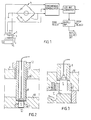
- Fig. 1 shows an eddy-current sensor 1 which can be used for the method and the device according to the invention.
- the sensor 1 comprises two coils 2,3 that are connected as in a Wheatstone bridge. These coils 2,3 are fed with a high frequency alternating current of 50 kHz to 10 MHz, preferably 125 kHz, from an oscillator circuit 4.
- the lower coil 2 is located close to the inner surface of the engine cylinder (not shown) and defines a measurement coil.
- the sensor 1 generates a magnetic field.
- a piston head 5 made of electrically conducting material is subjected to the magnetic field as it reaches its upper dead-centre position. Eddy currents are thereby induced in the piston head 5.
- the electromagnetic field is to a major part or almost exclusively generated by the measurement coil 2.
- the inductive reactance in the coil 2 will increase due to the high permeability in the piston head 5. If the piston head 5 comprises a non-magnetic material, the electromagnetic field of the coil 2 will induce eddy currents in the surface of the piston head 5. The electromagnetic field that is generated in the piston head 5 will counteract the magnetic field of the coil 2 and thereby induce a change of the reactance in the coil 2. The amplitude change of the reactance depends on the distance between coil 2 and piston head 5.
- the resistance and permeability of the piston head material will determine the performance of the device.
- Non-magnetic materials such as aluminium, copper, gold etc. have a low resistance and permeability around 1. This results in a relatively high sensibility and a large possible measurement distance.
- the high resistance and/or permeability of materials such as iron or nickel-steel counteracts an effective generation of eddy-currents.
- the optimal piston head material is therefore aluminium.
- the sensor 1 must withstand the harsh conditions encountered in the combustion chamber 11, especially the heat and pressure alterations that occur in an engine under operation. Therefor the sensor 1 is pre-strained with a force that is larger than the gas forces in the operation cycle of the engine.
- a protective shield 7 of an electrically non-conducting material here a ceramic ring made of Boron nitride.
- the sensor body 1 is connected to a sleeve 8.
- the sensor body 1 and sleeve 8 form an elongated element that is inserted in a bore that extends through outer wall 9 of the cylinder head of the engine and through an inner wall 10 of the same cylinder head. Between said walls there is a channel for cooling water. Accordingly, also the sensor will be subjected to cooling provided by the engine's cooling system.
- a threaded stop element 12 is connected to the sleeve 8 and in engagement with a thread 13 provided at the inner periphery of the bore in the outer wall 9. The stop element 12 transmits the vertical force on the device to the outer wall 9.
- the means 14 is a screw driven into the inner wall 10 from the inner surface thereof.
- a pit 15 in the piston head 5 there is also shown a pit 15 in the piston head 5. It should be noted that differences in the surface structure of the piston head 5 does not affect the accuracy of the measurement as the eddy-current sensor 1 senses the mean value of the total surface covered by the magnetic field.
- the eddy-current sensor 1 After calibration and measure value adjustment, even based on type of fuel, the eddy-current sensor 1, then tailored to the engine, may be used for determining how the engine and each relevant construction part is physically affected and affects the tip clearance at different rpm, temperature and loads. Moreover, the piston tilting and the total effect of different plays, such as gliding, rolling etc., and oil films can be determined based on the measurement by means of the sensor 1.
- the sleeve 8 surrounds the sensor body 1 and is provided with a thread 16 and in engagement with a corresponding thread in the bore in the inner wall 10.
- An inner sleeve 8' is arranged inside the sleeve 8.
- the inner sleeve 8' extends from the sensor 1 to the stop element 12. It is displaceable inside the outer sleeve 8 and it is pre-strained against the sensor by means of the stop element 12. Thereby, the sensor can be pre-strained by means of the stop element 12.
- the outer and inner sleeves 8,8' are preferably provided engagement means such as a groove, projection or the like (not shown) for permitting them to be screwed out of the bores in the cylinder from outside said cylinder by means of any torque applying means, such as a screwdriver.
- engagement means such as a groove, projection or the like (not shown) for permitting them to be screwed out of the bores in the cylinder from outside said cylinder by means of any torque applying means, such as a screwdriver.
- the sensor 1 and the sleeve 8 connected thereto can be replaced by a threaded plug 17, shown in fig 5 .
- the measurement could also be used in order to calibrate the engine's specific calculation system for calculating the tip clearance before delivery of the engine.
- the sensor 1 is arranged such that it can be removed from outside the cylinder head.
- the plug 17 can, in a similar way, be inserted into the bore from outside the cylinder head. Any kind of thread seal is preferably provided between the threads that are in engagement with each
- a device for adjusting or controlling the compression in the combustion chamber 11 during the operation of the engine displaces the cylinder part 18 of the motor block in relation to the crankcase part 19. Thereby, the distance between the tip of the piston head 5 and the inner surface of the cylinder head will be variable or can be maintained generally constant at different rpm, loads and engine temperatures.
- the cylinder part 18 comprises a first flange 21 and the crankcase part 19 comprises a corresponding second flange 22 arranged to be in engagement with the first flange 21, and the device comprises a means 20 for displacing the cylinder part 18 in relation to the crankcase part 19 through a sliding movement between said flanges 21,22.
- reference number 20 indicates a hydraulic piston/cylinder arrangement for displacing the cylinder part 18 sideways in relation to the crankcase part 19.
- a removable distance element preferably a washer 29 might be provided between the piston /cylinder arrangement 20 and the cylinder part 18 in order to individually pre-set the displacement of the cylinder part 18, for example before the cylinder possibly would be firmly connected to other cylinders.
- a screw arrangement with the same principal task and function.
- FIG. 7 there is shown an alternative embodiment of the device in fig. 6 , which comprises rotary rods 24 or the like that are eccentrically arranged and generally cylindrical.
- the rods 24 rotate around an axis 25, which is displaced in relation to the centre axis of the respective rod 24.
- the rod or rods 24 are supported by the motor block (not shown in fig. 7 ).
- Reference number 26 indicates a heel or ribbon on the first flange 21. A heel is preferred when the cylinders of the cylinder part are individually arranged and a ribbon is preferred when the cylinders are mounted in one piece.
- the rods or cylinders 24 are in engagement with respective heels or ribbons 26, and induces the displacement of the cylinder part 18 in relation to the crankcase part 19 upon rolling thereof.
- the device has to be provided with a means 27, such as a rubber cloth, for obtaining a closed system that encloses the sliding surfaces and possible lubricating oil used therein.
- a means 27 such as a rubber cloth
- ring or a bearing 28 arranged on the rods 24.
- the ring 28 is of such material that it decreases the friction between rods 24 and heel/ribbon 26.
- Engines having separate cylinders may have a separate ring or bearing 28 for each cylinder in order to adjust each cylinder individually, for example with reference to a nominal cylinder.
- the inventive device can include only one eddy-current sensor 1 for the purpose of determining the tip-clearance of an individual piston, the determined tip-clearance being used as a base for the adjustment of the tip-clearance and/or compression for that single cylinder or for a plurality of cylinders of a plural cylinder engine.
- the determination of the tip-clearance i.e. the upper dead-centre point, can be done at a regular basis in order to directly act as a basis for an immediate engine compression control. However, it may also be performed at generally irregular basis, for example in order to up-date an algorithm based on which the engine compression is controlled.
- the eddy-current sensor 1 should always be adapted to the prevailing operation conditions, such as fuel used, temperature, and other engine characteristics. Therefor re-calibration of the sensor might be needed at a more or less regular basis.
- ⁇ there is preferably a tilting angle ⁇ between the gliding plane of the parts 21,22 in relation to the horizontal plane, preferably -15° to 15°.
Landscapes
- Engineering & Computer Science (AREA)
- Chemical & Material Sciences (AREA)
- Combustion & Propulsion (AREA)
- Mechanical Engineering (AREA)
- General Engineering & Computer Science (AREA)
- Physics & Mathematics (AREA)
- General Physics & Mathematics (AREA)
- Measurement Of Length, Angles, Or The Like Using Electric Or Magnetic Means (AREA)
- Output Control And Ontrol Of Special Type Engine (AREA)
- Cylinder Crankcases Of Internal Combustion Engines (AREA)
- Combined Controls Of Internal Combustion Engines (AREA)
Description
- The present invention relates to a method of determining and adjusting the upper dead-centre position in piston engines, in which the position of the piston is measured by an eddy-current sensor.
- It also relates to a device for determining and adjusting the upper dead-centre position in a piston engine comprising a unit having an electrically operated sensor for measuring the position of the piston, said sensor being an eddy-current sensor.
- The tip clearance is one of the most import factors in engine design. The less tip clearance, the less fuel consumption and less emissions of so called greenhouse gases. Therefore, it would be of advantage to be able to determine and control the distance between the piston tip or head and the cylinder head during engine operation, and at different rpm and different loads and temperatures.
- Based on measurements of the tip clearance under relevant operation conditions, calculation models describing the tip clearance that are more accurate than contemporary theoretic model studies, such as FEM, would be possible to achieve.
-
US patent 4, 147,054 discloses a method and an apparatus for determining the upper dead-centre position in piston engines. The determination of the dead-centre position is based on a distance measurement, in which the distance between a sensor and the piston is measured. The sensor is either a capacitive distance-measuring transmitter of conventional construction or an inductive distance-measuring transmitter of conventional construction. - The capacitive distance-measuring transmitter is very sensitive to changes in the dielectric in the gap between sensor and the measuring surface, i.e. the piston head. Because the dielectric constant in the combustion gases is difficult to determine and also will change during the combustion, it will be difficult to obtain acceptable values on the tip clearance by means of such a capacitive distance-measuring transmitter.
- The inductive distance-measuring transmitter has the disadvantage of only being applicable for the measurement on ferromagnetic materials such as iron. Accordingly, it will not serve for the measurement of aluminium pistons. It is also sensitive to temperatures and pressures and need to be protected from the combustion chamber environment. For the measurement regions that are most likely, typically up to 2 mm, the inductive sensor requires slightly more space than would be desired.
-
US-A-4 589 278 describes a system by means of which the upper dead-centre of a piston is detected by means of an eddy-current sensor. The sensor may be mounted permanently or temporarily in a cylinder head for continuous measurement or initial calibration of top dead-centre against crank shaft position. Knowledge about the piston position as the engine operates is used for optimisation of the engine performance. - Also
US-A-4 535 624 discloses the use of an eddy-current sensor for the purpose of detecting the upper dead-centre of the piston of an internal combustion engine. The object of the measurement is to detect the timing of the upper dead-centre position, in order to monitor deviations in the maximum travel of the piston. By detecting deviations in the travel of the piston, premature engine failure, caused by, for example, bearing wear, shaft misalignment, etc, may be foreseen and thereby avoided. -
US-A-4 385 297 discloses a engine in which there is provided a piston position detector of eddy current type designed in such a way that it is not susceptible to falling out of calibration as a result of vibration or shock and that is immune to hostile environmental conditions. The sensor is used for signalling the stroking of the piston of a fluid actuator. -
EP-A-0 398 012 also discloses an eddy current sensor used for the purpose of determining the position of a piston operating in a cylinder. The document does not disclose in detail how to make use of the information obtained by means of the sensor. - It is further known from
US 5 914 593 A to use an eddy current sensor for measuring displacement of an object, in particular in hard to reach areas where temperature gradients may exist. In one embodiment a first coil and a second (reference) coil are integrated in a housing and connected in a Wheatstone bridge. The coils are fed with AC by an oscillator circuit such that the amplitude change of the reactance of the first coil depends on the distance between the coil and the target, eg. a flat aluminium target. - It is one object of the invention to provide a method and a device that makes use of a measurement of the upper dead centre position of a piston in a combustion engine in a new way, contributing to an improved efficiency and performance of the engine.
- The device should be reliable in operation, relatively cheap to manufacture and easy to handle and insert in the engine the tip clearance of which is to be determined and controlled.
- The object of the invention is achieved by a method according to
independent claim 1 and a device according to independent claim 9. - The piston head of the engine comprises an electrically conducting material, and eddy currents are induced therein by means of generating a current in a coil in the eddy-current sensor. The impact of these eddy-currents on the reactance in a coil of the eddy-current sensor is determined.
- Preferably the determination of the upper dead-centre position is performed under dynamic operating conditions of the engine.
- The device may further comprise means connected to said unit, said means being arranged for affecting the compression in the engine based on the upper dead-centre position determined by means of the eddy-current sensor.
- The device comprises a coil and means for inducing a current through said coil, said coil being positioned such that an eddy-current will be induced in the piston head as a result of it being subjected to a magnetic field from said coil.
- The device also comprises a coil in which the reactance is affected by the eddy currents induced in the piston head, and the determination of the dead-centre position is based on how said reactance is affected by the eddy-current.
- Preferably, the coil for inducing the eddy-current in the piston head and the coil the reactance of which is affected by the eddy-current are one and the same measurement coil, forming a part of the eddy-current sensor.
- According to one embodiment the inventive device comprises at least one temperature indicator for indicating the temperature that the eddy-current sensor is subjected to. The at least one temperature indicator comprises a reference coil connected to the measurement coil in a Wheatstone bridge.
- The eddy-current sensor is located in a bore arranged in the cylinder head of the engine.
- The bore extends through the cylinder head such that the eddy-current sensor is removable from outside the mounted cylinder head via the bore. Thereby, if desired, the sensor can be easily removed and replaced by a plug.
- According to one embodiment, the means for affecting the engine compression comprises a means for displacing the cylinder part of the engine in relation to the crankcase part thereof.
- Further, the engine may comprise at least two cylinders, each provided with a dedicated eddy-current sensor, and the device may comprise a means for affecting the engine compression individually for each cylinder.
- The invention may also use a device for adjusting the combustion chamber volume and the compression in the combustion chamber of a piston engine wherein a cylinder part of the engine is displaceable in relation to a crankcase part thereof. Thereby, the cylinder part is displaceable in relation to the crankcase part along a common sliding plane between cylinder part and crankcase part. Preferably, the cylinder part comprises a first flange and the crankcase comprises a corresponding second flange arranged to be in engagement with the first flange, and the device comprises a means for displacing the cylinder part in relation to the crankcase part through a sliding movement between said flanges. The displacement between cylinder part and crankcase part is preferably based on the determined tip clearance or on an algorithm based on the determined tip clearance.
- Further features and advantages of the present invention are presented in the following detailed description of preferred embodiments of the invention and in the appended claims.
- Preferred embodiments of the invention will now be described by way of example with reference to the accompanying drawings, on which:
-
Fig. 1 is a schematic diagram of an eddy-current sensor which may be used for the method and the device according to the invention. -
Fig.2 is a schematic cross-section view of a first embodiment of the inventive device for determination of a piston upper-dead position; -
Fig. 3 is a schematic cross-section view of the inventive device for determination of a piston upper-dead position, and the piston; -
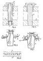
Fig. 4 is a schematic cross-section view of an alternative embodiment of the inventive device; -
Fig. 5 is a side view of a replacement plug for insertion in a hole in a cylinder part for replacement of the eddy-current sensor; -
Fig. 6 is a schematic cross section view of a device for adjusting the compression in a piston engine; -
Fig. 7 is a schematic cross-section view of an alternative embodiment of a device for adjusting the compression in a piston engine; -
Fig. 8 is a cross-section view along A-A infig. 7 . -
Fig. 1 shows an eddy-current sensor 1 which can be used for the method and the device according to the invention. Thesensor 1 comprises twocoils coils - The
lower coil 2 is located close to the inner surface of the engine cylinder (not shown) and defines a measurement coil. Theupper coil 3, located more remote from said inner surface, defines a reference coil for the purpose of indicating temperature differences and variations in the sensor. Since the measurement by themeasurement coil 2 changes with changing temperatures, the inventive device might comprise a plurality of temperature sensors. As an alternative or supplement the device might be provided with means for water cooling thesensor 1 order to obtain a more constant temperature. Thesensor 1 generates a magnetic field. Apiston head 5 made of electrically conducting material is subjected to the magnetic field as it reaches its upper dead-centre position. Eddy currents are thereby induced in thepiston head 5. The electromagnetic field is to a major part or almost exclusively generated by themeasurement coil 2. - If the
piston head 5 comprises a ferro-magnetic material, the inductive reactance in thecoil 2 will increase due to the high permeability in thepiston head 5. If thepiston head 5 comprises a non-magnetic material, the electromagnetic field of thecoil 2 will induce eddy currents in the surface of thepiston head 5. The electromagnetic field that is generated in thepiston head 5 will counteract the magnetic field of thecoil 2 and thereby induce a change of the reactance in thecoil 2. The amplitude change of the reactance depends on the distance betweencoil 2 andpiston head 5. - The resistance and permeability of the piston head material will determine the performance of the device. Non-magnetic materials such as aluminium, copper, gold etc. have a low resistance and permeability around 1. This results in a relatively high sensibility and a large possible measurement distance. The high resistance and/or permeability of materials such as iron or nickel-steel counteracts an effective generation of eddy-currents. The optimal piston head material is therefore aluminium.
- In order to obtain the best possible results, a calibration of the
sensor 1 against the same material as the piston head material should be performed before using thesensor 1 in its operative position in the engine cylinder. - The
sensor 1 must withstand the harsh conditions encountered in thecombustion chamber 11, especially the heat and pressure alterations that occur in an engine under operation. Therefor thesensor 1 is pre-strained with a force that is larger than the gas forces in the operation cycle of the engine. - As seen in
fig. 2 , the corners or edges of the sensor most adjacent thecombustion chamber 11 are protected by means of aprotective shield 7 of an electrically non-conducting material, here a ceramic ring made of Boron nitride. - With reference now to
fig. 2 , thesensor body 1 is connected to asleeve 8. Thesensor body 1 andsleeve 8 form an elongated element that is inserted in a bore that extends through outer wall 9 of the cylinder head of the engine and through aninner wall 10 of the same cylinder head. Between said walls there is a channel for cooling water. Accordingly, also the sensor will be subjected to cooling provided by the engine's cooling system. A threadedstop element 12 is connected to thesleeve 8 and in engagement with athread 13 provided at the inner periphery of the bore in the outer wall 9. Thestop element 12 transmits the vertical force on the device to the outer wall 9. - According to one embodiment, shown in
fig. 3 , there is provided ameans 14 for preventing theceramic ring 7 from falling into thecombustion chamber 11. The means 14 is a screw driven into theinner wall 10 from the inner surface thereof. Infig. 3 there is also shown apit 15 in thepiston head 5. It should be noted that differences in the surface structure of thepiston head 5 does not affect the accuracy of the measurement as the eddy-current sensor 1 senses the mean value of the total surface covered by the magnetic field. - After calibration and measure value adjustment, even based on type of fuel, the eddy-
current sensor 1, then tailored to the engine, may be used for determining how the engine and each relevant construction part is physically affected and affects the tip clearance at different rpm, temperature and loads. Moreover, the piston tilting and the total effect of different plays, such as gliding, rolling etc., and oil films can be determined based on the measurement by means of thesensor 1. - With reference to
fig. 4 there is shown an alternative embodiment in which thesleeve 8 surrounds thesensor body 1 and is provided with athread 16 and in engagement with a corresponding thread in the bore in theinner wall 10. An inner sleeve 8' is arranged inside thesleeve 8. The inner sleeve 8' extends from thesensor 1 to thestop element 12. It is displaceable inside theouter sleeve 8 and it is pre-strained against the sensor by means of thestop element 12. Thereby, the sensor can be pre-strained by means of thestop element 12. The outer andinner sleeves 8,8' are preferably provided engagement means such as a groove, projection or the like (not shown) for permitting them to be screwed out of the bores in the cylinder from outside said cylinder by means of any torque applying means, such as a screwdriver. After installation and operation, for example in order to check the tip clearance at a regular engine service occasion, thesensor 1 and thesleeve 8 connected thereto can be replaced by a threadedplug 17, shown infig 5 . The measurement could also be used in order to calibrate the engine's specific calculation system for calculating the tip clearance before delivery of the engine. Thesensor 1 is arranged such that it can be removed from outside the cylinder head. Theplug 17 can, in a similar way, be inserted into the bore from outside the cylinder head. Any kind of thread seal is preferably provided between the threads that are in engagement with each other. - With reference to
fig. 6 there is shown a device for adjusting or controlling the compression in thecombustion chamber 11 during the operation of the engine. The device displaces thecylinder part 18 of the motor block in relation to thecrankcase part 19. Thereby, the distance between the tip of thepiston head 5 and the inner surface of the cylinder head will be variable or can be maintained generally constant at different rpm, loads and engine temperatures. - The
cylinder part 18 comprises afirst flange 21 and thecrankcase part 19 comprises a correspondingsecond flange 22 arranged to be in engagement with thefirst flange 21, and the device comprises ameans 20 for displacing thecylinder part 18 in relation to thecrankcase part 19 through a sliding movement between saidflanges - In the device in
fig. 6 reference number 20 indicates a hydraulic piston/cylinder arrangement for displacing thecylinder part 18 sideways in relation to thecrankcase part 19. A removable distance element, preferably awasher 29 might be provided between the piston /cylinder arrangement 20 and thecylinder part 18 in order to individually pre-set the displacement of thecylinder part 18, for example before the cylinder possibly would be firmly connected to other cylinders. As an alternative to the piston/cylinder arrangement there could be provided a screw arrangement with the same principal task and function. - In
fig. 7 there is shown an alternative embodiment of the device infig. 6 , which comprises rotary rods 24 or the like that are eccentrically arranged and generally cylindrical. The rods 24 rotate around anaxis 25, which is displaced in relation to the centre axis of the respective rod 24. The rod or rods 24 are supported by the motor block (not shown infig. 7 ).Reference number 26 indicates a heel or ribbon on thefirst flange 21. A heel is preferred when the cylinders of the cylinder part are individually arranged and a ribbon is preferred when the cylinders are mounted in one piece. The rods or cylinders 24 are in engagement with respective heels orribbons 26, and induces the displacement of thecylinder part 18 in relation to thecrankcase part 19 upon rolling thereof. - Possibly, the device has to be provided with a
means 27, such as a rubber cloth, for obtaining a closed system that encloses the sliding surfaces and possible lubricating oil used therein. - In
fig. 7 there is also shown ring or abearing 28 arranged on the rods 24. Thering 28 is of such material that it decreases the friction between rods 24 and heel/ribbon 26. - Engines having separate cylinders may have a separate ring or bearing 28 for each cylinder in order to adjust each cylinder individually, for example with reference to a nominal cylinder.
- The design of a possible cross section of the engagement between the
parts fig. 8 , resulting in sideways stability between theparts - With regard to what has been stated above by way of example, it should be realised that a plurality of alternative embodiments will be obvious for a man skilled in the art without thereby departing from the scope of the invention as defined by the appended claims.
- It should be understood that the inventive device can include only one eddy-
current sensor 1 for the purpose of determining the tip-clearance of an individual piston, the determined tip-clearance being used as a base for the adjustment of the tip-clearance and/or compression for that single cylinder or for a plurality of cylinders of a plural cylinder engine. The determination of the tip-clearance, i.e. the upper dead-centre point, can be done at a regular basis in order to directly act as a basis for an immediate engine compression control. However, it may also be performed at generally irregular basis, for example in order to up-date an algorithm based on which the engine compression is controlled. - The eddy-
current sensor 1 should always be adapted to the prevailing operation conditions, such as fuel used, temperature, and other engine characteristics. Therefor re-calibration of the sensor might be needed at a more or less regular basis. - As seen in
fig. 7 , there is preferably a tilting angle α between the gliding plane of theparts
Claims (15)
- A method for determining the upper dead-centre position of a piston (5) moving in a cylinder of an internal combustion engine, and for adjustment of tip clearance and/or compression in said cylinder or in a plurality of cylinders of said internal combustion engine, in which clearance
the position of the piston (5) is measured through distance measurement by means of an eddy-current sensor, comprising the step of arranging an eddy-current sensor (1) in a bore through a cylinder head (9, 10) of the engine,
wherein the step of measure value adjustment is carried out by means of arranging, in the eddy-current sensor (1),- a first coil (2) located adjacent the inner surface of the cylinder , serving as a measurement coil;- a second coil (3) located remote from the inner surface, serving as a reference coil indicating temperature differences and variations in the sensor;- connecting the two coils (2, 3) in a Wheatstone bridge and feeding the coils with an alternating current, an amplitude change of the reactance of the first coil (2) depending on the distance between the first coil (2) and the head of the piston (5); and- protecting the corners or edges of the eddy-current sensor (1) most adjacent the combustion chamber (11) by means of a protective shield (7) of an electrically non-conducting material. - The method of claim 1, comprising the step of arranging a plurality of temperature sensors in the eddy current sensor (1).
- The method of claim 1 or 2, comprising the step of arranging the eddy current sensor so as to be subjected to cooling by the engine's cooling system.
- The method according to any of claims 1-3, wherein the shield (7) is a ceramic Boron nitride ring.
- The method according to any of claims 1-4, comprising the step of pre-straining the eddy-current sensor (1) with a force that is larger than the gas forces generated in the operation cycle of the engine, by means of mutually displaceable outer (8) and inner (8') sleeves and a stop element (12) effective for pre-straining the eddy-current sensor (1) in the bore.
- The method according to any of claims 1-5, wherein the piston's head (5) comprises an electrically conducting material and eddy currents are induced therein by means of generating a current in the coil (2) in the eddy-current sensor, and the impact of these eddy-currents on the reactance in the coil (2) of the eddy-current sensor is determined.
- The method according to claim 6, wherein the reactance in the coil (2) is affected by the eddy currents induced in the piston (5) head and determination of the dead-centre position is based on how said reactance is affected by the eddy-current.
- The method according to any previous claim, wherein the determination of the dead-centre position is performed under dynamic operating conditions of the engine.
- A device for determining the upper dead-centre position of a piston (5) moving in a cylinder of an internal combustion engine, and for adjustment of tip clearance and/or compression in said cylinder or in a plurality of cylinders of said internal combustion engine, the device comprising an eddy-current sensor (1) configured to be arranged in a bore through a cylinder head (9, 10) of the engine, wherein the eddy-current sensor (1) comprises:- a first coil (2) arranged to be located adjacent the inner surface of the cylinder , serving as a measurement coil;- a second coil (3) arranged to be located remote from the inner surface, serving as a reference coil indicating temperature differences and variationsin the sensor;- the two coils (2, 3) being connected in a Wheatstone bridge connectable to an oscillator circuit for feeding the coils with an alternating current, such that an amplitude change of the reactance of the first coil (2) depending on the distance between the first coil (2) and the head of the piston (5),- wherein the device further comprises a protective shield (7) of an electrically non-conducting material arranged for protecting the corners or edges of the eddy-current sensor (1) most adjacent the combustion chamber (11).
- The device of claim 9, wherein the eddy current sensor (1) comprises a plurality of temperature sensors.
- The device of claim 9 or 10, wherein the eddy current sensor (1) is configured for cooling by the engine's cooling system.
- The device according to any of claim 9-11, wherein the shield (7) is a ceramic Boron nitride ring.
- The device according to any of claims 9-12, comprising outer (8) and inner (8') sleeves in displaceable engagement and a stop element (12) effective for pre-straining the eddy-current sensor (1) .
- The device according to any of claims 9-13, further comprising means (4) for inducing a current through said first and second coils (2, 3), the coil (2) being positioned such that an eddy-current will be induced in the piston's head (5) as a result of it being subjected to a magnetic field from said coil (2).
- The device according to claim 14, wherein the coil for inducing the eddy-current in the piston's head and the coil the reactance of which is affected by the eddy-current are one and the same measurement coil (2), forming part of the eddy-current sensor (1).
Applications Claiming Priority (3)
| Application Number | Priority Date | Filing Date | Title |
|---|---|---|---|
| SE9904554 | 1999-12-14 | ||
| SE9904554A SE9904554D0 (en) | 1999-12-14 | 1999-12-14 | Devices for measuring and controlling peak play during operation on internal combustion engines of the reciprocating piston type |
| PCT/SE2000/002528 WO2001044750A1 (en) | 1999-12-14 | 2000-12-14 | Method and device for determining and adjusting the upper dead-centre position in piston engines |
Publications (2)
| Publication Number | Publication Date |
|---|---|
| EP1247066A1 EP1247066A1 (en) | 2002-10-09 |
| EP1247066B1 true EP1247066B1 (en) | 2013-05-22 |
Family
ID=20418104
Family Applications (1)
| Application Number | Title | Priority Date | Filing Date |
|---|---|---|---|
| EP00987901.6A Expired - Lifetime EP1247066B1 (en) | 1999-12-14 | 2000-12-14 | Method and device for determining and adjusting the upper dead-centre position in piston engines |
Country Status (15)
| Country | Link |
|---|---|
| US (1) | US6810722B2 (en) |
| EP (1) | EP1247066B1 (en) |
| JP (2) | JP4749644B2 (en) |
| KR (1) | KR20030040194A (en) |
| CN (2) | CN1185460C (en) |
| AU (1) | AU783740B2 (en) |
| BR (1) | BR0016346A (en) |
| CA (1) | CA2394158A1 (en) |
| MX (1) | MXPA02005920A (en) |
| NO (1) | NO20022642L (en) |
| RU (2) | RU2275590C2 (en) |
| SE (1) | SE9904554D0 (en) |
| TR (1) | TR200201583T2 (en) |
| WO (1) | WO2001044750A1 (en) |
| ZA (1) | ZA200205521B (en) |
Families Citing this family (20)
| Publication number | Priority date | Publication date | Assignee | Title |
|---|---|---|---|---|
| FR2911956B1 (en) * | 2007-01-29 | 2009-05-08 | Hispano Suiza Sa | DEVICE FOR MEASURING THE POSITION OF A PISTON IN A CYLINDER, A SET OF A CYLINDER, A PISTON AND A SUCH DEVICE AND AN AIRCRAFT ENGINE COMPRISING SUCH AN ASSEMBLY |
| CN101624940A (en) * | 2008-07-10 | 2010-01-13 | 郑九昂 | Variable compression ratio of engines |
| FR2939189A1 (en) * | 2008-12-01 | 2010-06-04 | Renault Sas | Combustion flame and inner wall contacting distance determining method for internal combustion engine, involves determining distance between flame and wall by specific relationship comprising parameters such as limit voltage and current |
| US20100249982A1 (en) * | 2009-03-24 | 2010-09-30 | Buffalo Machinery Company Limited | Displacement compensation control method and module for an object mounted movably on a driving rod unit |
| CN101858722B (en) * | 2010-05-25 | 2011-12-14 | 中国兵器工业集团第七○研究所 | Detection device of working top dead center of diesel engine |
| CN101936229A (en) * | 2010-07-23 | 2011-01-05 | 高伟 | Variable volume compression ratio engine |
| CN102094716A (en) * | 2011-03-14 | 2011-06-15 | 高伟 | Variable compression ratio engine |
| EP2703622B1 (en) * | 2012-08-31 | 2014-12-31 | Caterpillar Motoren GmbH & Co. KG | Cylinder head with sensor sleeve |
| CN104074607B (en) * | 2013-03-28 | 2016-10-26 | 比亚迪股份有限公司 | Piston stop position detects device and has electromotor and the vehicle of this device |
| JP5960744B2 (en) * | 2014-03-25 | 2016-08-02 | Dmg森精機株式会社 | Adjustment method of engine combustion chamber volume |
| JP5897630B2 (en) * | 2014-03-25 | 2016-03-30 | Dmg森精機株式会社 | Adjustment method of engine combustion chamber volume |
| DE102015102233B4 (en) * | 2015-02-17 | 2019-05-29 | Asm Automation Sensorik Messtechnik Gmbh | Position sensor and thus created measuring arrangement |
| RU2626613C2 (en) * | 2015-09-02 | 2017-07-31 | Игорь Владимирович Долгих | Ice with variable compression ratio |
| US20170102364A1 (en) * | 2015-10-07 | 2017-04-13 | Andreas Hill | Ascertaining position of a piston in a cylinder |
| FR3066817B1 (en) * | 2017-05-29 | 2019-08-16 | MCE 5 Development | MEASURING DEVICE FOR AN INTERNAL COMBUSTION ENGINE COMPRISING A TARGET PASSING DETECTOR AND MOTOR COMPRISING SUCH A MEASURING DEVICE |
| JP7309109B2 (en) * | 2017-10-27 | 2023-07-18 | 株式会社三井E&S Du | engine system |
| UA122597C2 (en) * | 2018-08-13 | 2020-12-10 | Олександр Федорович Маленко | DEVICE FOR ADJUSTING THE DEGREE OF COMPRESSION OF AN INTERNAL COMBUSTION PISTON ENGINE |
| KR20210047438A (en) | 2019-10-21 | 2021-04-30 | 현대자동차주식회사 | Bearing gap measuring device and method |
| CN113074947A (en) * | 2021-03-16 | 2021-07-06 | 上海中船三井造船柴油机有限公司 | Positioning device and method for top dead center of marine low-speed diesel engine |
| CN114352411A (en) * | 2021-12-20 | 2022-04-15 | 中国北方发动机研究所(天津) | Remote sensing measuring device for dynamic clearance of engine piston cylinder sleeve |
Citations (7)
| Publication number | Priority date | Publication date | Assignee | Title |
|---|---|---|---|---|
| US1838256A (en) * | 1929-12-30 | 1931-12-29 | David Franklin Cook | Internal combustion engine |
| US4174683A (en) * | 1978-01-20 | 1979-11-20 | Vivian Howard C | High efficiency variable expansion ratio engine |
| US4385297A (en) * | 1980-01-14 | 1983-05-24 | Schmitt Wilhelm E | Arrangement for sensing proximity of a reciprocating member |
| US4535624A (en) * | 1983-06-01 | 1985-08-20 | The Indikon Company, Inc. | Engine monitoring system |
| US4589278A (en) * | 1984-05-31 | 1986-05-20 | Indikon Corporation | Detection of top of stroke of piston |
| EP0398012A2 (en) * | 1989-05-12 | 1990-11-22 | Robert Bosch Gmbh | Working cylinder with a sensor for the determination of the position of the piston |
| US5914593A (en) * | 1993-06-21 | 1999-06-22 | Micro Strain Company, Inc. | Temperature gradient compensation circuit |
Family Cites Families (20)
| Publication number | Priority date | Publication date | Assignee | Title |
|---|---|---|---|---|
| DE2404231A1 (en) * | 1974-01-30 | 1975-07-31 | Viktor Rosenau | Variable compression ratio system for I.C. engines - cylinder block is raised or lowered in relation to crank case until equilibrium is reached |
| DE2655064A1 (en) | 1976-12-04 | 1978-06-08 | Daimler Benz Ag | METHOD AND DEVICE FOR DETERMINING THE TOP DEAD POINT IN PISTON MACHINERY |
| JPS57110904A (en) * | 1980-12-27 | 1982-07-10 | Nippon Steel Corp | Eddy-current system displacement gauge |
| SU1441183A1 (en) * | 1986-12-02 | 1988-11-30 | Челябинский Институт Механизации И Электрификации Сельского Хозяйства | Method of measuring clearance between cylinder linear and compression ring of piston internal combustion engine |
| JPH01145951A (en) * | 1987-11-30 | 1989-06-07 | Shinkuraito:Kk | Vibration type lead frame conveying device |
| AT389944B (en) * | 1987-11-30 | 1990-02-26 | Avl Verbrennungskraft Messtech | CAPACITIVE MEASURING SYSTEM FOR DISTANCE DETERMINATION |
| JP2597019B2 (en) | 1990-01-19 | 1997-04-02 | 三菱重工業株式会社 | Piston ring wear diagnosis method |
| US5036236A (en) * | 1990-05-07 | 1991-07-30 | Hughes Aircraft Company | Air gap matching proximity sensor for magnetic bearings |
| DE4120822A1 (en) * | 1991-06-24 | 1993-01-07 | Martin Schmidt | Engine crankshaft misalignment control support - has hydraulic thruster coupled by levers to cylinder block and crankcase |
| DE4211589A1 (en) | 1992-04-07 | 1993-10-14 | Audi Ag | Reciprocating internal combustion engine with variable compression |
| JPH06137176A (en) * | 1992-10-22 | 1994-05-17 | Toyota Motor Corp | Variable structure of displacement and compression ratio in internal combustion engine |
| US5342176A (en) * | 1993-04-05 | 1994-08-30 | Sunpower, Inc. | Method and apparatus for measuring piston position in a free piston compressor |
| JPH0726981A (en) * | 1993-06-25 | 1995-01-27 | Eiji Miyai | Internal combustion engine of variable compression ratio |
| US5428992A (en) * | 1994-06-13 | 1995-07-04 | General Electric Company | Generating a once-per-cycle signal for a locomotive diesel engine |
| JPH08121230A (en) * | 1994-10-31 | 1996-05-14 | Kubota Corp | Top dead center position detection device for piston and injection timing setting device for fuel injection pump |
| RU2099561C1 (en) * | 1995-03-07 | 1997-12-20 | Анатолий Захарович Багерман | Device for operation of internal combustion engine |
| FR2746848B1 (en) * | 1996-03-27 | 1998-05-29 | Condamin Bernard | VARIABLE VOLUMETRIC RATIO ENGINE AND MOUNTING METHOD THEREOF |
| US5906222A (en) * | 1996-08-07 | 1999-05-25 | General Electric Company | Apparatus for detecting position of piston in hydraulic actuator coupled to gate valve |
| US6155109A (en) * | 1997-12-22 | 2000-12-05 | Caterpillar Inc. | System and method for measuring piston ring rotation |
| JP3593282B2 (en) * | 1999-05-19 | 2004-11-24 | 本田技研工業株式会社 | Sensor mounting structure for piston behavior analysis |
-
1999
- 1999-12-14 SE SE9904554A patent/SE9904554D0/en unknown
-
2000
- 2000-12-14 JP JP2001545798A patent/JP4749644B2/en not_active Expired - Fee Related
- 2000-12-14 TR TR2002/01583T patent/TR200201583T2/en unknown
- 2000-12-14 CA CA002394158A patent/CA2394158A1/en not_active Abandoned
- 2000-12-14 MX MXPA02005920A patent/MXPA02005920A/en unknown
- 2000-12-14 WO PCT/SE2000/002528 patent/WO2001044750A1/en not_active Ceased
- 2000-12-14 CN CNB008171831A patent/CN1185460C/en not_active Expired - Fee Related
- 2000-12-14 RU RU2002119013/28A patent/RU2275590C2/en not_active IP Right Cessation
- 2000-12-14 US US10/149,698 patent/US6810722B2/en not_active Expired - Lifetime
- 2000-12-14 EP EP00987901.6A patent/EP1247066B1/en not_active Expired - Lifetime
- 2000-12-14 AU AU24169/01A patent/AU783740B2/en not_active Ceased
- 2000-12-14 KR KR1020027007601A patent/KR20030040194A/en not_active Ceased
- 2000-12-14 CN CNB2004101000058A patent/CN100394001C/en not_active Expired - Fee Related
- 2000-12-14 RU RU2005119212/06A patent/RU2322597C2/en not_active IP Right Cessation
- 2000-12-14 BR BR0016346-5A patent/BR0016346A/en not_active Application Discontinuation
-
2002
- 2002-06-05 NO NO20022642A patent/NO20022642L/en not_active Application Discontinuation
- 2002-07-10 ZA ZA200205521A patent/ZA200205521B/en unknown
-
2010
- 2010-03-10 JP JP2010052939A patent/JP2010156346A/en active Pending
Patent Citations (7)
| Publication number | Priority date | Publication date | Assignee | Title |
|---|---|---|---|---|
| US1838256A (en) * | 1929-12-30 | 1931-12-29 | David Franklin Cook | Internal combustion engine |
| US4174683A (en) * | 1978-01-20 | 1979-11-20 | Vivian Howard C | High efficiency variable expansion ratio engine |
| US4385297A (en) * | 1980-01-14 | 1983-05-24 | Schmitt Wilhelm E | Arrangement for sensing proximity of a reciprocating member |
| US4535624A (en) * | 1983-06-01 | 1985-08-20 | The Indikon Company, Inc. | Engine monitoring system |
| US4589278A (en) * | 1984-05-31 | 1986-05-20 | Indikon Corporation | Detection of top of stroke of piston |
| EP0398012A2 (en) * | 1989-05-12 | 1990-11-22 | Robert Bosch Gmbh | Working cylinder with a sensor for the determination of the position of the piston |
| US5914593A (en) * | 1993-06-21 | 1999-06-22 | Micro Strain Company, Inc. | Temperature gradient compensation circuit |
Also Published As
| Publication number | Publication date |
|---|---|
| RU2322597C2 (en) | 2008-04-20 |
| EP1247066A1 (en) | 2002-10-09 |
| TR200201583T2 (en) | 2002-12-23 |
| NO20022642L (en) | 2002-08-15 |
| MXPA02005920A (en) | 2003-10-14 |
| RU2002119013A (en) | 2004-03-10 |
| JP2003517535A (en) | 2003-05-27 |
| US20030177821A1 (en) | 2003-09-25 |
| AU783740B2 (en) | 2005-12-01 |
| SE9904554D0 (en) | 1999-12-14 |
| CN1409815A (en) | 2003-04-09 |
| BR0016346A (en) | 2002-09-10 |
| WO2001044750A1 (en) | 2001-06-21 |
| CA2394158A1 (en) | 2001-06-21 |
| WO2001044750A8 (en) | 2002-07-04 |
| CN100394001C (en) | 2008-06-11 |
| CN1185460C (en) | 2005-01-19 |
| ZA200205521B (en) | 2003-10-14 |
| AU2416901A (en) | 2001-06-25 |
| RU2275590C2 (en) | 2006-04-27 |
| RU2005119212A (en) | 2006-12-27 |
| CN1782348A (en) | 2006-06-07 |
| US6810722B2 (en) | 2004-11-02 |
| KR20030040194A (en) | 2003-05-22 |
| NO20022642D0 (en) | 2002-06-05 |
| JP2010156346A (en) | 2010-07-15 |
| JP4749644B2 (en) | 2011-08-17 |
Similar Documents
| Publication | Publication Date | Title |
|---|---|---|
| US6810722B2 (en) | Method and device for determining and adjusting the upper dead-center position in piston engines | |
| KR101387809B1 (en) | Device for directly measuring on a piston the effective volumetric ratio of a variable compression ratio engine | |
| EP2500705A1 (en) | Method for the determination of the pressure in the combustion chamber of a large diesel engine and large diesel engine | |
| KR20200105424A (en) | Variable displacement reciprocating piston unit generating pistion stroke speed and pistion stroke length signal | |
| US7007563B2 (en) | Monitor to check the path of motion of reciprocating piston | |
| US6536266B1 (en) | Piston behavior analyzing sensor mounting structure and piston behavior analyzing method | |
| CN1175247C (en) | Method and device for determining the state of motion in a cylinder of an internal combustion engine | |
| Söchting et al. | The effect of load and viscosity on the minimum operating oil film thickness of piston-rings in internal combustion engines | |
| JP2013256886A (en) | Free piston generator | |
| US7257994B2 (en) | Measuring device and method for determining the position of an electrically conductive test object | |
| JP2003129902A (en) | piston ring | |
| Higgs et al. | The development and application of advanced sensor solutions for gaining new insights into large engines | |
| JPS6118961B2 (en) | ||
| AU605942B2 (en) | Apparatus for detecting the position of a piston ring in an internal combustion engine | |
| Charron | Paper III (ii) | |
| KR200183503Y1 (en) | Apparatus for sensing the ignition timing using magnetic tape | |
| Charron | Measurement of oil film thickness in diesel motor main bearings: implementation of the method and experimental results | |
| WO2003002946A1 (en) | Method to determine an angular position of a flywheel | |
| JPS6175207A (en) | Measurement of thickness of piston ring | |
| CN108474705A (en) | Pressure monitoring device and method | |
| JPH04140430A (en) | Method for detecting overheat of piston in internal combustion engine | |
| JPH0732203U (en) | Measuring device for working amount of hydraulic cylinder | |
| JPS5851268A (en) | Apparatus for measuring fuel injection timing | |
| KR19980029181A (en) | Cylinder bore measuring device |
Legal Events
| Date | Code | Title | Description |
|---|---|---|---|
| PUAI | Public reference made under article 153(3) epc to a published international application that has entered the european phase |
Free format text: ORIGINAL CODE: 0009012 |
|
| 17P | Request for examination filed |
Effective date: 20020628 |
|
| AK | Designated contracting states |
Kind code of ref document: A1 Designated state(s): AT BE CH CY DE DK ES FI FR GB GR IE IT LI LU MC NL PT SE TR |
|
| AX | Request for extension of the european patent |
Free format text: AL;LT PAYMENT 20020628;LV;MK;RO;SI |
|
| 17Q | First examination report despatched |
Effective date: 20071214 |
|
| RIC1 | Information provided on ipc code assigned before grant |
Ipc: G01B 7/14 20060101AFI20120926BHEP Ipc: F02B 77/08 20060101ALI20120926BHEP Ipc: F02D 15/04 20060101ALI20120926BHEP Ipc: F02F 7/00 20060101ALI20120926BHEP |
|
| GRAP | Despatch of communication of intention to grant a patent |
Free format text: ORIGINAL CODE: EPIDOSNIGR1 |
|
| GRAJ | Information related to disapproval of communication of intention to grant by the applicant or resumption of examination proceedings by the epo deleted |
Free format text: ORIGINAL CODE: EPIDOSDIGR1 |
|
| GRAP | Despatch of communication of intention to grant a patent |
Free format text: ORIGINAL CODE: EPIDOSNIGR1 |
|
| RAP1 | Party data changed (applicant data changed or rights of an application transferred) |
Owner name: JONSSON, BERTH Owner name: JONSSON, JONAS |
|
| RIN1 | Information on inventor provided before grant (corrected) |
Inventor name: JONSSON, BERTH Inventor name: JONSSON, JONAS |
|
| GRAS | Grant fee paid |
Free format text: ORIGINAL CODE: EPIDOSNIGR3 |
|
| GRAA | (expected) grant |
Free format text: ORIGINAL CODE: 0009210 |
|
| AK | Designated contracting states |
Kind code of ref document: B1 Designated state(s): AT BE CH CY DE DK ES FI FR GB GR IE IT LI LU MC NL PT SE TR |
|
| AX | Request for extension of the european patent |
Extension state: LT |
|
| REG | Reference to a national code |
Ref country code: GB Ref legal event code: FG4D |
|
| REG | Reference to a national code |
Ref country code: CH Ref legal event code: EP |
|
| REG | Reference to a national code |
Ref country code: AT Ref legal event code: REF Ref document number: 613446 Country of ref document: AT Kind code of ref document: T Effective date: 20130615 |
|
| REG | Reference to a national code |
Ref country code: IE Ref legal event code: FG4D |
|
| REG | Reference to a national code |
Ref country code: DE Ref legal event code: R096 Ref document number: 60048034 Country of ref document: DE Effective date: 20130718 |
|
| REG | Reference to a national code |
Ref country code: SE Ref legal event code: TRGR |
|
| REG | Reference to a national code |
Ref country code: AT Ref legal event code: MK05 Ref document number: 613446 Country of ref document: AT Kind code of ref document: T Effective date: 20130522 |
|
| REG | Reference to a national code |
Ref country code: LT Ref legal event code: MG9D |
|
| PG25 | Lapsed in a contracting state [announced via postgrant information from national office to epo] |
Ref country code: GR Free format text: LAPSE BECAUSE OF FAILURE TO SUBMIT A TRANSLATION OF THE DESCRIPTION OR TO PAY THE FEE WITHIN THE PRESCRIBED TIME-LIMIT Effective date: 20130823 Ref country code: ES Free format text: LAPSE BECAUSE OF FAILURE TO SUBMIT A TRANSLATION OF THE DESCRIPTION OR TO PAY THE FEE WITHIN THE PRESCRIBED TIME-LIMIT Effective date: 20130902 Ref country code: PT Free format text: LAPSE BECAUSE OF FAILURE TO SUBMIT A TRANSLATION OF THE DESCRIPTION OR TO PAY THE FEE WITHIN THE PRESCRIBED TIME-LIMIT Effective date: 20130923 Ref country code: AT Free format text: LAPSE BECAUSE OF FAILURE TO SUBMIT A TRANSLATION OF THE DESCRIPTION OR TO PAY THE FEE WITHIN THE PRESCRIBED TIME-LIMIT Effective date: 20130522 |
|
| REG | Reference to a national code |
Ref country code: NL Ref legal event code: VDEP Effective date: 20130522 |
|
| PG25 | Lapsed in a contracting state [announced via postgrant information from national office to epo] |
Ref country code: DK Free format text: LAPSE BECAUSE OF FAILURE TO SUBMIT A TRANSLATION OF THE DESCRIPTION OR TO PAY THE FEE WITHIN THE PRESCRIBED TIME-LIMIT Effective date: 20130522 Ref country code: BE Free format text: LAPSE BECAUSE OF FAILURE TO SUBMIT A TRANSLATION OF THE DESCRIPTION OR TO PAY THE FEE WITHIN THE PRESCRIBED TIME-LIMIT Effective date: 20130522 |
|
| PG25 | Lapsed in a contracting state [announced via postgrant information from national office to epo] |
Ref country code: IT Free format text: LAPSE BECAUSE OF FAILURE TO SUBMIT A TRANSLATION OF THE DESCRIPTION OR TO PAY THE FEE WITHIN THE PRESCRIBED TIME-LIMIT Effective date: 20130522 Ref country code: NL Free format text: LAPSE BECAUSE OF FAILURE TO SUBMIT A TRANSLATION OF THE DESCRIPTION OR TO PAY THE FEE WITHIN THE PRESCRIBED TIME-LIMIT Effective date: 20130522 |
|
| PLBE | No opposition filed within time limit |
Free format text: ORIGINAL CODE: 0009261 |
|
| STAA | Information on the status of an ep patent application or granted ep patent |
Free format text: STATUS: NO OPPOSITION FILED WITHIN TIME LIMIT |
|
| 26N | No opposition filed |
Effective date: 20140225 |
|
| REG | Reference to a national code |
Ref country code: DE Ref legal event code: R097 Ref document number: 60048034 Country of ref document: DE Effective date: 20140225 |
|
| PG25 | Lapsed in a contracting state [announced via postgrant information from national office to epo] |
Ref country code: LU Free format text: LAPSE BECAUSE OF FAILURE TO SUBMIT A TRANSLATION OF THE DESCRIPTION OR TO PAY THE FEE WITHIN THE PRESCRIBED TIME-LIMIT Effective date: 20131214 Ref country code: MC Free format text: LAPSE BECAUSE OF FAILURE TO SUBMIT A TRANSLATION OF THE DESCRIPTION OR TO PAY THE FEE WITHIN THE PRESCRIBED TIME-LIMIT Effective date: 20130522 |
|
| REG | Reference to a national code |
Ref country code: IE Ref legal event code: MM4A |
|
| PG25 | Lapsed in a contracting state [announced via postgrant information from national office to epo] |
Ref country code: IE Free format text: LAPSE BECAUSE OF NON-PAYMENT OF DUE FEES Effective date: 20131214 |
|
| PG25 | Lapsed in a contracting state [announced via postgrant information from national office to epo] |
Ref country code: CY Free format text: LAPSE BECAUSE OF FAILURE TO SUBMIT A TRANSLATION OF THE DESCRIPTION OR TO PAY THE FEE WITHIN THE PRESCRIBED TIME-LIMIT Effective date: 20130522 Ref country code: TR Free format text: LAPSE BECAUSE OF FAILURE TO SUBMIT A TRANSLATION OF THE DESCRIPTION OR TO PAY THE FEE WITHIN THE PRESCRIBED TIME-LIMIT Effective date: 20130522 |
|
| REG | Reference to a national code |
Ref country code: FR Ref legal event code: PLFP Year of fee payment: 16 |
|
| PGFP | Annual fee paid to national office [announced via postgrant information from national office to epo] |
Ref country code: GB Payment date: 20160629 Year of fee payment: 16 Ref country code: FI Payment date: 20160628 Year of fee payment: 16 |
|
| PGFP | Annual fee paid to national office [announced via postgrant information from national office to epo] |
Ref country code: FR Payment date: 20160629 Year of fee payment: 16 |
|
| PG25 | Lapsed in a contracting state [announced via postgrant information from national office to epo] |
Ref country code: FI Free format text: LAPSE BECAUSE OF NON-PAYMENT OF DUE FEES Effective date: 20161214 |
|
| PGFP | Annual fee paid to national office [announced via postgrant information from national office to epo] |
Ref country code: CH Payment date: 20170629 Year of fee payment: 17 |
|
| GBPC | Gb: european patent ceased through non-payment of renewal fee |
Effective date: 20161214 |
|
| REG | Reference to a national code |
Ref country code: FR Ref legal event code: ST Effective date: 20170831 |
|
| PG25 | Lapsed in a contracting state [announced via postgrant information from national office to epo] |
Ref country code: FR Free format text: LAPSE BECAUSE OF NON-PAYMENT OF DUE FEES Effective date: 20170102 |
|
| PGFP | Annual fee paid to national office [announced via postgrant information from national office to epo] |
Ref country code: DE Payment date: 20170629 Year of fee payment: 17 |
|
| PG25 | Lapsed in a contracting state [announced via postgrant information from national office to epo] |
Ref country code: GB Free format text: LAPSE BECAUSE OF NON-PAYMENT OF DUE FEES Effective date: 20161214 |
|
| PGFP | Annual fee paid to national office [announced via postgrant information from national office to epo] |
Ref country code: SE Payment date: 20170629 Year of fee payment: 17 |
|
| REG | Reference to a national code |
Ref country code: DE Ref legal event code: R119 Ref document number: 60048034 Country of ref document: DE |
|
| REG | Reference to a national code |
Ref country code: CH Ref legal event code: PL |
|
| PG25 | Lapsed in a contracting state [announced via postgrant information from national office to epo] |
Ref country code: SE Free format text: LAPSE BECAUSE OF NON-PAYMENT OF DUE FEES Effective date: 20171215 |
|
| PG25 | Lapsed in a contracting state [announced via postgrant information from national office to epo] |
Ref country code: DE Free format text: LAPSE BECAUSE OF NON-PAYMENT OF DUE FEES Effective date: 20180703 |
|
| PG25 | Lapsed in a contracting state [announced via postgrant information from national office to epo] |
Ref country code: LI Free format text: LAPSE BECAUSE OF NON-PAYMENT OF DUE FEES Effective date: 20171231 Ref country code: CH Free format text: LAPSE BECAUSE OF NON-PAYMENT OF DUE FEES Effective date: 20171231 |