EP1246477A2 - Gateway system and fault management method - Google Patents
Gateway system and fault management method Download PDFInfo
- Publication number
- EP1246477A2 EP1246477A2 EP02007046A EP02007046A EP1246477A2 EP 1246477 A2 EP1246477 A2 EP 1246477A2 EP 02007046 A EP02007046 A EP 02007046A EP 02007046 A EP02007046 A EP 02007046A EP 1246477 A2 EP1246477 A2 EP 1246477A2
- Authority
- EP
- European Patent Office
- Prior art keywords
- network
- gateway
- media gateway
- switched circuit
- media
- Prior art date
- Legal status (The legal status is an assumption and is not a legal conclusion. Google has not performed a legal analysis and makes no representation as to the accuracy of the status listed.)
- Withdrawn
Links
Images





Classifications
-
- H—ELECTRICITY
- H04—ELECTRIC COMMUNICATION TECHNIQUE
- H04L—TRANSMISSION OF DIGITAL INFORMATION, e.g. TELEGRAPHIC COMMUNICATION
- H04L65/00—Network arrangements, protocols or services for supporting real-time applications in data packet communication
- H04L65/10—Architectures or entities
- H04L65/102—Gateways
- H04L65/1033—Signalling gateways
- H04L65/104—Signalling gateways in the network
-
- H—ELECTRICITY
- H04—ELECTRIC COMMUNICATION TECHNIQUE
- H04L—TRANSMISSION OF DIGITAL INFORMATION, e.g. TELEGRAPHIC COMMUNICATION
- H04L65/00—Network arrangements, protocols or services for supporting real-time applications in data packet communication
- H04L65/10—Architectures or entities
- H04L65/102—Gateways
- H04L65/1023—Media gateways
- H04L65/103—Media gateways in the network
-
- H—ELECTRICITY
- H04—ELECTRIC COMMUNICATION TECHNIQUE
- H04L—TRANSMISSION OF DIGITAL INFORMATION, e.g. TELEGRAPHIC COMMUNICATION
- H04L65/00—Network arrangements, protocols or services for supporting real-time applications in data packet communication
- H04L65/10—Architectures or entities
- H04L65/102—Gateways
- H04L65/1043—Gateway controllers, e.g. media gateway control protocol [MGCP] controllers
-
- H—ELECTRICITY
- H04—ELECTRIC COMMUNICATION TECHNIQUE
- H04L—TRANSMISSION OF DIGITAL INFORMATION, e.g. TELEGRAPHIC COMMUNICATION
- H04L65/00—Network arrangements, protocols or services for supporting real-time applications in data packet communication
- H04L65/1066—Session management
- H04L65/1101—Session protocols
-
- H—ELECTRICITY
- H04—ELECTRIC COMMUNICATION TECHNIQUE
- H04L—TRANSMISSION OF DIGITAL INFORMATION, e.g. TELEGRAPHIC COMMUNICATION
- H04L67/00—Network arrangements or protocols for supporting network services or applications
- H04L67/14—Session management
-
- H—ELECTRICITY
- H04—ELECTRIC COMMUNICATION TECHNIQUE
- H04L—TRANSMISSION OF DIGITAL INFORMATION, e.g. TELEGRAPHIC COMMUNICATION
- H04L67/00—Network arrangements or protocols for supporting network services or applications
- H04L67/50—Network services
- H04L67/56—Provisioning of proxy services
-
- H—ELECTRICITY
- H04—ELECTRIC COMMUNICATION TECHNIQUE
- H04L—TRANSMISSION OF DIGITAL INFORMATION, e.g. TELEGRAPHIC COMMUNICATION
- H04L69/00—Network arrangements, protocols or services independent of the application payload and not provided for in the other groups of this subclass
- H04L69/40—Network arrangements, protocols or services independent of the application payload and not provided for in the other groups of this subclass for recovering from a failure of a protocol instance or entity, e.g. service redundancy protocols, protocol state redundancy or protocol service redirection
-
- H—ELECTRICITY
- H04—ELECTRIC COMMUNICATION TECHNIQUE
- H04L—TRANSMISSION OF DIGITAL INFORMATION, e.g. TELEGRAPHIC COMMUNICATION
- H04L9/00—Cryptographic mechanisms or cryptographic arrangements for secret or secure communications; Network security protocols
- H04L9/40—Network security protocols
-
- H—ELECTRICITY
- H04—ELECTRIC COMMUNICATION TECHNIQUE
- H04M—TELEPHONIC COMMUNICATION
- H04M3/00—Automatic or semi-automatic exchanges
- H04M3/22—Arrangements for supervision, monitoring or testing
- H04M3/2254—Arrangements for supervision, monitoring or testing in networks
-
- H—ELECTRICITY
- H04—ELECTRIC COMMUNICATION TECHNIQUE
- H04M—TELEPHONIC COMMUNICATION
- H04M7/00—Arrangements for interconnection between switching centres
- H04M7/12—Arrangements for interconnection between switching centres for working between exchanges having different types of switching equipment, e.g. power-driven and step by step or decimal and non-decimal
- H04M7/1205—Arrangements for interconnection between switching centres for working between exchanges having different types of switching equipment, e.g. power-driven and step by step or decimal and non-decimal where the types of switching equipement comprises PSTN/ISDN equipment and switching equipment of networks other than PSTN/ISDN, e.g. Internet Protocol networks
- H04M7/125—Details of gateway equipment
- H04M7/1255—Details of gateway equipment where the switching fabric and the switching logic are decomposed such as in Media Gateway Control
-
- H—ELECTRICITY
- H04—ELECTRIC COMMUNICATION TECHNIQUE
- H04Q—SELECTING
- H04Q3/00—Selecting arrangements
- H04Q3/0016—Arrangements providing connection between exchanges
- H04Q3/0025—Provisions for signalling
-
- H—ELECTRICITY
- H04—ELECTRIC COMMUNICATION TECHNIQUE
- H04L—TRANSMISSION OF DIGITAL INFORMATION, e.g. TELEGRAPHIC COMMUNICATION
- H04L41/00—Arrangements for maintenance, administration or management of data switching networks, e.g. of packet switching networks
- H04L41/06—Management of faults, events, alarms or notifications
- H04L41/0654—Management of faults, events, alarms or notifications using network fault recovery
- H04L41/0659—Management of faults, events, alarms or notifications using network fault recovery by isolating or reconfiguring faulty entities
-
- H—ELECTRICITY
- H04—ELECTRIC COMMUNICATION TECHNIQUE
- H04L—TRANSMISSION OF DIGITAL INFORMATION, e.g. TELEGRAPHIC COMMUNICATION
- H04L67/00—Network arrangements or protocols for supporting network services or applications
- H04L67/50—Network services
- H04L67/56—Provisioning of proxy services
- H04L67/565—Conversion or adaptation of application format or content
-
- H—ELECTRICITY
- H04—ELECTRIC COMMUNICATION TECHNIQUE
- H04L—TRANSMISSION OF DIGITAL INFORMATION, e.g. TELEGRAPHIC COMMUNICATION
- H04L69/00—Network arrangements, protocols or services independent of the application payload and not provided for in the other groups of this subclass
- H04L69/30—Definitions, standards or architectural aspects of layered protocol stacks
- H04L69/32—Architecture of open systems interconnection [OSI] 7-layer type protocol stacks, e.g. the interfaces between the data link level and the physical level
- H04L69/322—Intralayer communication protocols among peer entities or protocol data unit [PDU] definitions
- H04L69/329—Intralayer communication protocols among peer entities or protocol data unit [PDU] definitions in the application layer [OSI layer 7]
-
- H—ELECTRICITY
- H04—ELECTRIC COMMUNICATION TECHNIQUE
- H04M—TELEPHONIC COMMUNICATION
- H04M7/00—Arrangements for interconnection between switching centres
- H04M7/06—Arrangements for interconnection between switching centres using auxiliary connections for control or supervision, e.g. where the auxiliary connection is a signalling system number 7 link
Definitions
- the invention relates to a gateway system and a fault management method used on the gateway system, in particular, to a fault management method in a media gateway controller included in the gateway system.
- a PC Point Code
- SCN Switched Circuit Network
- a PC is assigned to each MGC (Media Gateway Controller).
- a method of maintenance and charging of the system is complicated and extra PCs are wasted since PC is assigned to each MGC.
- one PC can be assigned to each SG (signaling gateway) which is connected to a plurality of MGCs.
- SG signal gateway
- one of MGCs which are connected to the same SG having a fault (trouble) for example, due to a fault occurred in a LAN (Local Area Network) or a fault of the MGC itself, a call loss may occur or the SG (or PC code) may become inaccessible.
- a gateway system which provides an IP network service via an existing switched circuit network.
- the gateway system comprises (1) a media gateway which performs transformation of a media format required between the switched circuit network and an IP network, (2) a plurality of media gateway controllers each of which controls the media gateway and controls calls and connections of the IP network, and (3) a signaling gateway which performs signaling transfer between the switched circuit network and the IP network.
- the signaling gateway when a fault occurs on a media gateway controller side, the signaling gateway has a function to require an opposed node of the switched circuit network to perform a line close operation about lines controlled by the media gateway controller.
- a fault management method of a gateway system which provides an IP network service via an existing switched circuit network.
- the fault management method comprises the steps of (1) performing, at a media gateway, transformation of a media format required between the switched circuit network and an IP network, (2) controlling, at each of a plurality of media gateway controllers, the media gateway, and calls and connections of the IP network, (3) performing, at a signaling gateway, signaling transfer between the switched circuit network and the IP network, and (4) requiring, at the signaling gateway, when a fault occurs on a media gateway controller side, an opposed node of the switched circuit network to perform a line close operation about lines controlled by the media gateway controller.
- a gateway system of the invention in a gateway system providing an IP network service such as a RAS (Remote Access Service) or a VolP (Voice over IP (Internet Protocol)) using an existing SCN, a PC (Point Code) is supplied to an SG (Signaling Gateway) connected to a plurality of MGCs (Media Gateway Controller), and an occurrence of a call loss and an inaccessibility of the SG can be prevented by incorporating to the SG a function that requires line close operation for an opposed node of the SCN when a fault (for example, a fault occurred in a LAN (Local Area Network) or a fault of the MGC itself) occurs on the MGC which is structured to have no PC.
- a fault for example, a fault occurred in a LAN (Local Area Network) or a fault of the MGC itself
- the gateway system includes the SG which terminates a No. 7 signal and provides a signaling transfer function between the SCN and an IP (Internet Protocol) network, MGs (Media Gateway) each of which transforms required media data between the SCN and the IP network, and MGCs each of which controls the MG and controls calls and connection of the IP network.
- IP Internet Protocol
- a PC is assigned to each point and the PC is used as an address for routing of a signal message.
- the PC is assigned to each MGC.
- the PC is not assigned to each MGC, and the PC is assigned only to each SG which is connected to a plurality of MGCs. In this case, if the SG has no line state management function, when one of the MGCs which are connected to the same SG having a fault, a line which is controlled by another MGC connected to the SG may also become unavailable.
- a function is added to the SG.
- the function requires a line close operation about a line controlled by the MGC to an opposed node when a fault occurs on the MGC side.
- lines which are controlled by the other MGCs (which are connected to the same SG as the MGC having a fault) are kept available to prevent an occurrence of a call loss and an inaccessibility of the SG.
- a plurality of MGCs are connected to an SG, a PC is assigned to the SG and does not assigned to the plurality of the MGCs,
- the SG includes a No. 7 side signal processing unit, an IP side signal processing unit, and an MSG management unit.
- the No. 7 side signal processing unit has an MTP-L3 (Message Transfer Part - Level 3) function to terminate a No. 7 signal.
- MTP-L3 Message Transfer Part - Level 3
- the IP side signal processing unit has an M3UA (MTP3 - User Adaptation Layer) function to send a signal to an MGC via the IP network by using an SCTP (Stream Control Transmission Protocol).
- M3UA MTP3 - User Adaptation Layer
- SCTP Stream Control Transmission Protocol
- the MSG management unit has a function to manage states of MGCs and to send a message requiring a line close operation to an exchange of the SCN when a fault occurs on an MGC side.
- a line state management function is also required.
- the SG originally does not have the line state management function, therefore, a part of a function ISUP (ISDN User Part) is added to the SG.
- ISUP ISDN User Part
- Each of the plurality of MGCs has a function of the M3UA and a function of the ISUP, to terminate an ISUP signal. Also, the plurality of MGCs perform line state management and controlling of MG to control calls and a connection of the IP network.
- a media data stream is transferred between the plurality of MGs which are connected to the plurality of MGCs and an exchange of the SCN, via a bundle of communication lines. State of the communication lines are managed by the MGCs through the MGs. A line close signal of the bundle of communication lines (BLO (Blocking Message)/CGB (Circuit Group Blocking Message)) is issued by the MGCs, and sent to the exchange.
- BLO Blocking Message
- CGB Circuit Group Blocking Message
- the SG can send the line close signal (BLO/CGB) by using an MGC management unit when a fault occurs on the MGC side, the SG sends the line close signal (BLO/CGB) of a bundle of communication lines to the exchange at the time.
- the exchange makes only a bundle of communication lines related to the MGC having a fault unavailable.
- it is capable of using a bundle of communication lines related to the other MGCs which are not in trouble.
- the PC is not assigned to MGCs and is assigned to only a SG.
- the SG requires a line close operation to prevent an occurrence of a call loss and an inaccessibility of the SG.
- the conventional gateway system includes an SG (Signaling Gateway) 31, MGCs 8 and 9, MGs (Media Gateway) 4 and 5, and an exchange 6.
- the SG 31 is connected to an SS7 (Signaling System No. 7 (No. 7 common channel signaling)) network 100 via a signal link, and a No. 7 signal is transferred between the SG 31 and the exchange 6 of the SCN.
- SS7 Signal-to-Network Interface
- No. 7 signal is transferred between the SG 31 and the exchange 6 of the SCN.
- the SG 31 is connected to the MGCs 8, 9 via an IP network 30, and a signal is transferred between the SG 31 and the MGCs 8, 9.
- the MGCs 8 and 9 are connected to the MGs 4 and 5 via the IP network 30, respectively.
- PC#3 is assigned to the MGC 8 and PC#4 is assigned to the MGC 9.
- the exchange 6 is connected to the MGs 4 and 5 via bundles of communication lines 101 and 102.
- a plurality of subscriber's terminals 7 of users are connected to the exchange 6.
- an available communication line of the bundles 101 and 102 is used.
- Figs. 2 and 3 Sequences of processes are shown in Figs. 2 and 3 when the call loss occurs or the SG becomes inaccessible.
- Fig. 2 a sequence is shown when the call loss occurs.
- a fault a trouble
- a line close signal is not sent to the exchange of the SCN.
- the exchange 6 determines that the bundle of communication lines 101 connected to the MG 4 which is controlled by the MGC 8 is available, and sends to the SG 31 an ISUP (ISDN (Integrated Service Digital Network) User Part) signal which controls the bundle of communication lines 101 (E1 in Fig. 2).
- ISUP ISDN (Integrated Service Digital Network) User Part
- the SG 31 discards the ISUP signal (E1 in Fig. 2) since the SG 31 holds information representing that the fault occurs on the MGC side. Therefore, the exchange 6 cannot receive a response of the ISUP signal, then a timer of the exchange 6 determines that an established time expires and thereby a call loss occurs.
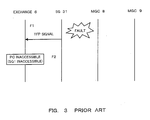
- a sequence is shown when the SG 31 becomes inaccessible.
- the SG 31 sends to the SCN a TFP (TransFer Prohibited) signal which is a signal network management signal of a MTP (Message Transfer Part).
- TFP TransFer Prohibited
- the SG 31 sends the TFP signal to the exchange 6 (F1 in Fig. 3).
- the exchange 6 disables accessing the SG 31 (F2 in Fig. 3).
- a bundle of communication lines 102 also becomes unavailable although the bundle 102 is controlled by the MGC which has no fault (trouble) at present.
- a gateway system includes an SG (Signaling Gateway) 1, MGCs (Media Gateway Controller) 2 and 3, MGs (Media Gateway) 4 and 5, and an exchange 6, and provides an IP network service via an SCN (Switched Circuit Network) by using the elements.
- SG Synignaling Gateway
- MGCs Media Gateway Controller
- MGs Media Gateway
- SCN Switchched Circuit Network
- a PC (Point Code) "PC#1" is assigned to the SG 1.
- the SG 1 is connected to an SS7 (Signaling System No. 7: No. 7 common channel signaling) network 100 via a signal link and a No. 7 signal is transferred between the SG1 and the exchange 6 of the SCN.
- the SG 1 is connected to the MGCs 2 and 3 via an IP (Internet Protocol) network 10 and a signal is transferred between them.
- IP Internet Protocol
- a PC is not assigned to the MGCs 2 and 3.
- the MGCs 2 and 3 are connected to the MGs 4 and 5, respectively, via the IP network 10 and a signal is transferred between them.
- the exchange 6 is connected to the MG 4 via a bundle of communication lines 101, and is also connected to the MG 5 via a bundle of communication lines 102.
- Subscriber's terminals 7 are connected to the exchange 6. When a user requires an IP network service by using one of the terminals 7, an available line is selected from the bundles 101 and 102, and the selected line is established as a communication line,
- Fig. 5 shows a block diagram representing a structure of the SG 1 shown in Fig. 4.
- the SG 1 includes a No. 7 side signal processing unit 11, an IP side signal processing unit 12, and an MGC management unit 13.
- the No. 7 side signal processing unit 11 has a function of MTP-L3 (Message Transfer Part - Level 3), and transfers a No. 7 signal between the unit 11 and the SS7 network.
- MTP-L3 Message Transfer Part - Level 3
- the No. 7 side signal processing unit 11 has a function to get a CIC (Circuit Identification Code) in an ISUP message, which is a MTP-L3 user message.
- the No. 7 side signal processing unit 11 transforms the received No. 7 signal into a proper signal and sends the transformed signal to the IP side signal processing unit 12.
- the IP side signal processing unit 12 has a function of M3UA (MTP (Message Transfer Part) 3 - User Adaptation layer), and sends the signal received from the No. 7 side signal processing unit 11 to the MGCs 2 and 3 via the IP network 10 by using SCTP (Stream Control Transmission Protocol).
- M3UA MTP (Message Transfer Part) 3 - User Adaptation layer
- SCTP Stream Control Transmission Protocol
- the MGC management unit 13 includes an MGC state management function 131, an MGC line close function 132, and an MGC state table 133.
- the MGC state management function 131 manages states of the MGCs 2 and 3.
- the MGC line close function 132 has a part of function of ISUP, and sends a line close signal (BLO/CGB: BLOcking message/Circuit Group Blocking message) to the SS7 network 100 via the No. 7 side signal processing unit 11 when a fault occurs on the MGC side, for example, a fault occurs on a LAN or on the MGC itself.
- the SG 1 stores a relationship between a communication line and an MGC which controls the communication line, and distributes a signal to the MGCs 2 and 3 by identifying a communication line based on a DPC (Destination Point Code) and a CIC (Circuit Identification Code) and selecting the corresponding MGC.
- DPC Disposination Point Code
- CIC Circuit Identification Code
- the DPC is a PC "PC#2" of the exchange 6, and the CIC represents a communication line selected from the bundles of communication lines 101 and 102.
- the MGCs 2 and 3 has a function of M3UA and a function of ISUP.
- the MGCs 2 and 3 can identify a communication line established between the exchange 6 and the MGs 4 and 5 from the DPC and the CIC.
- the MGCs 2 and 3 further manage states of lines and control the MGs 4 and 5 to control calls and connections of the IP network 10.
- Fig. 6 shows an example of the MGC state table 133 shown in Fig. 5. In Fig. 6, only a part which is related to the embodiment of the invention is shown. That is, in the MGC state table 133, MGC fault information and line close information are stored for each MGC.
- the MGC fault information represents whether a fault occurs on the MGC side or not. If the fault occurs on the MGC side, a value of "1" is set to the MGC fault information, otherwise, a value of "0" is set to the MGC fault information. Also, the line close information represents whether a line close operation is performed or not when a fault occurs on the MGC side. If the line close operation is performed, a value of "1” is set to the line close information, otherwise, a value of "0" is set to the line close information.
- Fig. 7 shows a sequence chart when the gateway system according to the embodiment of the invention operates normally.
- Fig. 8 shows a sequence chart of the gateway system according to the embodiment of the invention when a fault occurs.
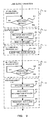
- Fig. 9 shows a flowchart representing a line close operation performed by the SG 1 shown in Fig. 5.
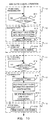
- Fig. 10 shows a flowchart representing a line close cancel operation performed by the SG 1 shown in Fig. 5.
- an IAM Intelligent Address Message
- ISUP Initial Address Message
- the SG 1 When the SG 1 receives the IAM, the SG 1 identifies a communication line based on a DPC and a CIC of an ISUP signal, and passes the IAM (ISUP) to the IP side signal processing unit 12 by using tunneling (A2 in Fig. 7).
- the function of M3UA of the IP side signal processing unit 12 distributes an IP signal (IAM (ISUP))to the MGC 2 (A3 in Fig. 7) by using an SCTP.
- IAM ISUP
- SCTP SCTP
- the MGC 2 controls the MG 4 according to contents of the IP signal, and returns the IP signal (ACM (Address Complete Message))(ISUP) to the SG 1 (A4 in Fig. 7).
- the IP side signal processing unit 12 of the SG 1 passes the ACM (ISUP) to the No. 7 side signal processing unit 11 by tunneling (A5 in Fig. 7), and the No. 7 side signal processing unit 11 sends the ACM (ISUP) to the exchange 6 via the SS7 network 100 (A6 in Fig. 7).
- each signal (B1 to B6 in Fig. 7) is transferred between the exchange 6 and the MGC 3 via the SG 1 according to a similar sequence described above.
- a fault information signal is sent from the IP side signal processing unit 12 to the MGC management unit 13 (C1 in Fig. 8), and thereby fault information is transferred.
- the MGC management unit 13 sends a line close signal of the bundle of communication lines 101 which is controlled by the MGC 2, to the No. 7 side signal processing unit 11 (C2 in Fig. 8).
- the No. 7 side signal processing unit 11 sends the line close signal (BLO/CGB) to the exchange 6 via the SS7 network 100 (C3 in Fig. 8).
- the exchange 6 When the exchange 6 receives the line close signal (C3 in Fig. 8), the exchange 6 closes all lines of the bundle 101 and sends a line close acknowledgement signal (BLA/CGBA : BLocking Acknowledgement message/Circuit Group Blocking Acknowledgement message) to the SG 1 via the SS7 network 100 (C4 in Fig. 8).
- BLA/CGBA BLocking Acknowledgement message/Circuit Group Blocking Acknowledgement message
- the exchange 6 selects a line of the bundle 102, and sends a control signal to the SS7 network 100, consequently a call control is performed by using the SG 1, the MGC 3, and the MG 5.
- the MGC line close function 132 searches the MGC state table 133.
- the function 132 When MGC fault information is registered in the table 133, but line close information is not registered in the table 133, the function 132 generates a line close signal to be sent to the MGC having a fault and transforms the MGC of the line close signal into a DPC and a CIC to send the signal to the MGC having a fault (step S3 in Fig. 9). Then, the No. 7 side signal processing unit 11 sends the transformed line close signal to the exchange 6 via the SS7 network (step S4 in Fig. 9).
- the MGC management unit 13 transforms the line close acknowledgement signal into an MG by using the DPC and the CIC (step S6 in Fig. 9).
- the MGC management unit 13 searches the MGC state table 133 for MGC fault information by using the transformed MGC, and confirms that the MGC is in trouble (step S7 in Fig. 9). Then, the unit 13 registers the line close information in an area, of the MGC state table 133, corresponding to the MGC (step S8 in Fig. 9).
- the SG 1 sends the line close cancel signal or the like to the No. 7 side signal processing unit 11 via the IP side signal processing unit 12 and the MGC management unit 13 (D2 and D3 in Fig. 8). Then, the No. 7 side signal processing unit 11 sends the line close cancel signal (UBL/CGU) to the exchange 6 via the SS7 network 100 (D4 in Fig. 8).
- UDL/CGU line close cancel signal
- the exchange 6 When the exchange 6 receives the line close cancel signal, the exchange 6 cancels blocking of the bundle of communication lines 101, makes them available, and sends a line close cancel acknowledgement signal (UBA/CGUA : UnBlocking Acknowledgement message/Circuit Group Unblocking Acknowledgement message) to the SG 1 via the SS7 network 100 (D5 in Fig. 8).
- UAA/CGUA UnBlocking Acknowledgement message/Circuit Group Unblocking Acknowledgement message
- the MGC management unit 13 searches the MGC state table 133 for MGC fault information and line close information based on the line close cancel signal, and confirms that the MGC falls into a line close state due to a fault (step S12 in Fig. 10). Then, the unit 13 transforms the MGC of the line close cancel signal into a DPC and a CIC (step S13 in Fig. 10). The No. 7 side signal processing unit 11 sends the transformed line close cancel signal to the exchange 6 via the SS7 network 100 (step S14 in Fig. 10).
- the MGC management unit 13 transforms the DPC and the CIC of the line close cancel acknowledgement signal into the MGC (step S16 in Fig. 10).
- the MGC management unit 13 searches the MGC state table 133 for MGC fault information and line close information by using the MGC, and confirms that the MGC falls into a line close state due to a fault (step S17 in Fig. 10). Then, the unit 13 deletes the MGC fault information and the line close information from the MGC state table 133 (step S18 in Fig. 10). Then, the IP side signal processing unit 12 sends a line close cancel acknowledgement signal to the corresponding MGC (step S19 in Fig. 10).
- each MGC (2, 3) controls a single MG (4, 5)
- a single MGC (2, 3) can control a plurality of MGs since each MGC stores a pair of a communication line and an MG which controls the communication line.
- the MGC distributes a signal to an MG identified by using a DPC and a CIC.
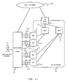
- Fig. 11 shows a block diagram of a gateway system according to another embodiment of the invention.
- each MGC (2, 3) is connected to a plurality of MGs (4 and 41, 5 and 51).
- the MGC 2 distributes a signal to MGs 4 and 41 by using a DPC and CIC.
- the MGC 3 distributes a signal to MGs 5 and 51 by using a DPC and a CIC.
- the MGCs 2 and 3 perform a management operation, and a line close signal is sent from the MGCs 2 and 3.
- the MGC 2 sends a line close signal of the bundle of communication lines 111 controlled by the MG 41, and SG 1 passes the signal to the exchange 6 of the SCN side.
- Fig. 12 shows a block diagram of a gateway system according to another embodiment of the invention.
- an MGC 21 is added and an IP address which is different from the IP address of the MGC 2 is assigned.
- the MGCs are prepared in a dual configuration (ACT (active)IS BY (standby)).
- Examples of configurations of gateway systems as shown in Figs. 11 and 12 can easily manage MGCs 2, 3, and 21 by giving a PC only to the SG 1.
- a gateway system which provides an IP network service via an existing switched circuit network.
- the system comprises (1) a media gateway which performs transformation of a media format required between the switched circuit network and an IP network, (2) a plurality of media gateway controllers each of which controls the media gateway and controls calls and connections of the IP network, and (3) a signaling gateway which performs signaling transfer between the switched circuit network and the IP network.
- the signaling gateway has a function to require an opposed node (for example, the exchange 6 connected to the SCN) of the switched circuit network to perform a line close operation about lines controlled by the media gateway controller.
- the gateway system can prevent a call loss and an inaccessibility of a PC (a signaling gateway) even if a fault occurs on the media gateway controller side, by giving to the signaling gateway the PC which is used as a routing address of a signal message. As a result, the gateway system can effectively utilize communication lines.
- a PC a signaling gateway
Landscapes
- Engineering & Computer Science (AREA)
- Computer Networks & Wireless Communication (AREA)
- Signal Processing (AREA)
- Multimedia (AREA)
- Computer Security & Cryptography (AREA)
- General Business, Economics & Management (AREA)
- Business, Economics & Management (AREA)
- Telephonic Communication Services (AREA)
- Data Exchanges In Wide-Area Networks (AREA)
- Mobile Radio Communication Systems (AREA)
- Small-Scale Networks (AREA)
- Time-Division Multiplex Systems (AREA)
- Monitoring And Testing Of Exchanges (AREA)
Abstract
Description
Claims (15)
- A gateway system which provides an IP network service via an existing switched circuit network comprising:a media gateway which performs transformation of a media format required between the switched circuit network and an IP network;a plurality of media gateway controllers each of which controls the media gateway and controls calls and connections of the IP network; anda signaling gateway which performs signaling transfer between the switched circuit network and the IP network, wherein when a fault occurs on a media gateway controller side, the signaling gateway has a function to require an opposed node of the switched circuit network to perform a line close operation about lines controlled by the media gateway controller.
- The gateway system of claim 1, wherein the IP network service includes a RAS or a VolP.
- The gateway system of claim 1, wherein a PC which is used as a routing address of a signal message is given to the signaling gateway and is not given to each of the plurality of the media gateway controllers.
- The gateway system of claim 3, wherein the function to require the opposed node to perform the line close operation is realized by a part of function of ISUP.
- The gateway system of claim 3, wherein the media gateway controller is configured to control one or more media gateway.
- The gateway system of claim 5, wherein an IP address is assigned to each of the plurality of media gateway controllers and the IP addresses are different from each other, and each of the plurality of media gateway controllers is configured to the same media gateway.
- A fault management method of a gateway system which provides an IP network service via an existing switched circuit network comprising the steps of:performing, at a media gateway, transformation of a media format required between the switched circuit network and an IP network;controlling, at each of a plurality of media gateway controllers, the media gateway, and calls and connections of the IP network;performing, at a signaling gateway, signaling transfer between the switched circuit network and the IP network; andrequiring, at the signaling gateway, when a fault occurs on a media gateway controller side, an opposed node of the switched circuit network to perform a line close operation about lines controlled by the media gateway controller.
- The method of claim 7, wherein the IP network service includes a RAS or a VolP.
- The method of claim 7, wherein a PC which is used as a routing address of a signal message is given to the signaling gateway and is not given to each of the plurality of the media gateway controllers.
- The method of claim 9, wherein the step of requiring is realized by a part of function of ISUP.
- The method of claim 9, wherein the media gateway controller is configured to control one or more media gateway.
- The method of claim 7, wherein an IP address is assigned to each of the plurality of media gateway controllers and the IP addresses are different from each other, and each of the plurality of media gateway controllers is configured to the same media gateway.
- A recording medium readable by a computer, tangibly embodying a program of instructions executable by the computer to perform a fault management method of a gateway system which provides an IP network service via an existing switched circuit network comprising the steps of:performing, at a media gateway, transformation of a media format required between the switched circuit network and an IP network;controlling, at each of a plurality of media gateway controllers, the media gateway, and calls and connections of the IP network;performing, at a signaling gateway, signaling transfer between the switched circuit network and the IP network; andrequiring, at the signaling gateway, when a fault occurs on a media gateway controller side, an opposed node of the switched circuit network to perform a line close operation about lines controlled by the media gateway controller.
- A computer data signal embodied in a carrier wave and representing a sequence of instructions which, when executed by a processor, cause the processor to perform a fault management method of a gateway system which provides an IP network service via an existing switched circuit network comprising the steps of:performing, at a media gateway, transformation of a media format required between the switched circuit network and an IP network;controlling, at each of a plurality of media gateway controllers, the media gateway, and calls and connections of the IP network;performing, at a signaling gateway, signaling transfer between the switched circuit network and the IP network; andrequiring, at the signaling gateway, when a fault occurs on a media gateway controller side, an opposed node of the switched circuit network to perform a line close operation about lines controlled by the media gateway controller.
- A program product comprising, computer readable instructions and a recording medium bearing the computer readable instructions, the instructions being adaptable to enable a computer to perform a fault management method of a gateway system which provides an IP network service via an existing switched circuit network comprising the steps of:performing, at a media gateway, transformation of a media format required between the switched circuit network and an IP network;controlling, at each of a plurality of media gateway controllers, the media gateway, and calls and connections of the IP network;performing, at a signaling gateway, signaling transfer between the switched circuit network and the IP network; andrequiring, at the signaling gateway, when a fault occurs on a media gateway controller side, an opposed node of the switched circuit network to perform a line close operation about lines controlled by the media gateway controller.
Applications Claiming Priority (2)
| Application Number | Priority Date | Filing Date | Title |
|---|---|---|---|
| JP2001091556 | 2001-03-28 | ||
| JP2001091556A JP2002290551A (en) | 2001-03-28 | 2001-03-28 | Gateway system and trouble processing method for use therein |
Publications (2)
| Publication Number | Publication Date |
|---|---|
| EP1246477A2 true EP1246477A2 (en) | 2002-10-02 |
| EP1246477A3 EP1246477A3 (en) | 2006-08-23 |
Family
ID=18946152
Family Applications (1)
| Application Number | Title | Priority Date | Filing Date |
|---|---|---|---|
| EP02007046A Withdrawn EP1246477A3 (en) | 2001-03-28 | 2002-03-27 | Gateway system and fault management method |
Country Status (9)
| Country | Link |
|---|---|
| US (1) | US7046684B2 (en) |
| EP (1) | EP1246477A3 (en) |
| JP (1) | JP2002290551A (en) |
| CN (1) | CN100379228C (en) |
| AR (1) | AR033020A1 (en) |
| AU (1) | AU2925202A (en) |
| BR (1) | BR0201938A (en) |
| MY (1) | MY130366A (en) |
| NZ (1) | NZ518073A (en) |
Cited By (6)
| Publication number | Priority date | Publication date | Assignee | Title |
|---|---|---|---|---|
| WO2004089003A1 (en) * | 2003-03-31 | 2004-10-14 | Siemens Aktiengesellschaft | Communication method between a media gateway controller and a media gateway |
| CN1309230C (en) * | 2004-04-06 | 2007-04-04 | 中兴通讯股份有限公司 | System and method for delivery of telecom signalling messages by passing private net boundary |
| WO2007051378A1 (en) | 2005-11-04 | 2007-05-10 | Huawei Technologies Co., Ltd | A method for decreasing the service loss of the intercommunication between the ss7 signaling network and m3ua |
| CN1319330C (en) * | 2003-08-19 | 2007-05-30 | 华为技术有限公司 | Fault information transmitting method |
| CN100461781C (en) * | 2003-07-15 | 2009-02-11 | 华为技术有限公司 | Method for Reporting Distributed Signaling Gateway Link Failure |
| CN101159719B (en) * | 2007-09-21 | 2012-11-07 | 北京大唐高鸿数据网络技术有限公司 | VoIP analogy gateway and inside switch method of implementing conversation under fault condition |
Families Citing this family (25)
| Publication number | Priority date | Publication date | Assignee | Title |
|---|---|---|---|---|
| KR100509870B1 (en) * | 2002-11-20 | 2005-08-22 | 엘지전자 주식회사 | Method for Interfacing between the Media Gateway and the Media Gateway Controller |
| US7490348B1 (en) | 2003-03-17 | 2009-02-10 | Harris Technology, Llc | Wireless network having multiple communication allowances |
| TWI239175B (en) * | 2003-04-28 | 2005-09-01 | Ind Tech Res Inst | Apparatus, system and method of signaling gateway |
| KR100952828B1 (en) | 2003-06-30 | 2010-04-15 | 주식회사 케이티 | How to Handle Soft Switch Failures in Next Generation Networks |
| CN1301604C (en) * | 2003-11-14 | 2007-02-21 | 中兴通讯股份有限公司 | Method for detecting H.248 protocol abnormal context |
| JP3880961B2 (en) * | 2003-12-19 | 2007-02-14 | シャープ株式会社 | Fixing method, fixing device, and image forming apparatus |
| KR100602652B1 (en) * | 2004-02-13 | 2006-07-19 | 삼성전자주식회사 | Routing management method of VIO system and its system |
| KR100990831B1 (en) | 2004-04-09 | 2010-10-29 | 엘지에릭슨 주식회사 | Softswitch and its method for overcoming obstacles in next generation networks |
| EP2200262A3 (en) * | 2004-06-30 | 2012-10-03 | Glenayre Electronics, Inc. | Auto block and auto discovery in a distributed communication |
| CN100334845C (en) * | 2004-07-21 | 2007-08-29 | 华为技术有限公司 | Method for detecting link failure between media getway and media gatway controller |
| CN100384261C (en) * | 2004-08-27 | 2008-04-23 | 华为技术有限公司 | A method for lossless transparent transmission of circuit identification codes based on M3UA |
| AU2005279575B2 (en) | 2004-08-29 | 2009-05-21 | Huawei Technologies Co., Ltd. | A method for implementing dual-homing |
| CN1327727C (en) * | 2005-04-18 | 2007-07-18 | 华为技术有限公司 | Method for realizing double homes of media gateway |
| CN1283070C (en) | 2004-09-10 | 2006-11-01 | 华为技术有限公司 | Monitoring method of media gateway controller state |
| US20070153813A1 (en) * | 2005-12-29 | 2007-07-05 | Level 3 Communications, Inc. | Traffic distribution in a communications network |
| CN101022545A (en) * | 2006-02-14 | 2007-08-22 | 华为技术有限公司 | A method and system for realizing multimedia playback through H.248 protocol |
| JP2007274256A (en) * | 2006-03-31 | 2007-10-18 | Nec Corp | Multiplexing system and communication controller |
| US20110310884A1 (en) * | 2006-09-14 | 2011-12-22 | Jesus-Javier Arauz-Rosado | Telephony endpoint routing in an ip multimedia subsystem |
| KR100851577B1 (en) | 2006-11-15 | 2008-08-12 | 주식회사 케이티프리텔 | Method and system for processing message in signal network |
| JP4810457B2 (en) | 2007-02-15 | 2011-11-09 | 富士通株式会社 | Gateway device |
| JP4470963B2 (en) | 2007-06-01 | 2010-06-02 | 株式会社日立製作所 | Gateway device, ONT and PON system |
| EP2222026B1 (en) * | 2007-11-12 | 2018-04-25 | Alcatel Lucent | A method and apparatus for processing a disconnection-connection between a media gateway and a media gateway controller |
| JP2009105923A (en) * | 2008-12-10 | 2009-05-14 | Hitachi Communication Technologies Ltd | Gateway device, ONT and PON system |
| JP2010212964A (en) * | 2009-03-10 | 2010-09-24 | Nec Corp | Network management system, media gateway device, fault notification method of media gateway device, and program |
| CN102724072A (en) * | 2012-06-20 | 2012-10-10 | 华为技术有限公司 | Method, unit and system for disaster recovery switching |
Family Cites Families (14)
| Publication number | Priority date | Publication date | Assignee | Title |
|---|---|---|---|---|
| JPS6041354A (en) | 1983-08-16 | 1985-03-05 | Nec Corp | Channel blocking system for trouble |
| JPH09214545A (en) | 1996-02-02 | 1997-08-15 | Nec Corp | Network communication control method |
| JP3099794B2 (en) | 1998-01-29 | 2000-10-16 | 日本電気株式会社 | Subscriber remote accommodation system and fault handling method thereof |
| JP3829467B2 (en) | 1998-03-30 | 2006-10-04 | Kddi株式会社 | Network routing controller |
| JPH11331269A (en) | 1998-05-12 | 1999-11-30 | Matsushita Electric Ind Co Ltd | Internet telephone call connection method and Internet telephone system |
| US6529499B1 (en) | 1998-09-22 | 2003-03-04 | Lucent Technologies Inc. | Method for providing quality of service for delay sensitive traffic over IP networks |
| EP1879354B1 (en) | 1998-12-04 | 2012-01-11 | Tekelec | Methods and systems for communicating SS7 messages |
| JP3633356B2 (en) | 1999-03-31 | 2005-03-30 | 株式会社日立製作所 | Server apparatus, service control gateway apparatus, service control apparatus, and communication control method |
| EP1177660B1 (en) * | 1999-04-27 | 2006-08-23 | Tekelec | Methods and systems for routing signaling messages in a communications network using circuit identification code (cic) information |
| US6735209B1 (en) * | 1999-07-29 | 2004-05-11 | Worldcom, Inc. | Address definition for IP telephony services |
| US6515985B2 (en) * | 2000-02-08 | 2003-02-04 | Airslide Systems Ltd. | Convergence of telephone signaling, voice and data over a packet-switched network |
| JP3747740B2 (en) * | 2000-05-22 | 2006-02-22 | 株式会社日立製作所 | Detour control method in Internet gateway system |
| US7318091B2 (en) | 2000-06-01 | 2008-01-08 | Tekelec | Methods and systems for providing converged network management functionality in a gateway routing node to communicate operating status information associated with a signaling system 7 (SS7) node to a data network node |
| US6944166B1 (en) | 2000-08-09 | 2005-09-13 | Nortel Networks Limited | Method for controlling service levels over packet based networks |
-
2001
- 2001-03-28 JP JP2001091556A patent/JP2002290551A/en active Pending
-
2002
- 2002-03-27 EP EP02007046A patent/EP1246477A3/en not_active Withdrawn
- 2002-03-27 US US10/106,231 patent/US7046684B2/en not_active Expired - Fee Related
- 2002-03-27 AR ARP020101129A patent/AR033020A1/en active IP Right Grant
- 2002-03-28 CN CNB021198292A patent/CN100379228C/en not_active Expired - Fee Related
- 2002-03-28 MY MYPI20021117 patent/MY130366A/en unknown
- 2002-03-28 NZ NZ518073A patent/NZ518073A/en unknown
- 2002-03-28 AU AU29252/02A patent/AU2925202A/en not_active Abandoned
- 2002-03-28 BR BR0201938-8A patent/BR0201938A/en not_active IP Right Cessation
Cited By (9)
| Publication number | Priority date | Publication date | Assignee | Title |
|---|---|---|---|---|
| WO2004089003A1 (en) * | 2003-03-31 | 2004-10-14 | Siemens Aktiengesellschaft | Communication method between a media gateway controller and a media gateway |
| DE10314542A1 (en) * | 2003-03-31 | 2004-10-28 | Siemens Ag | Method for communication between a media gateway controller and a media gateway |
| CN100461781C (en) * | 2003-07-15 | 2009-02-11 | 华为技术有限公司 | Method for Reporting Distributed Signaling Gateway Link Failure |
| CN1319330C (en) * | 2003-08-19 | 2007-05-30 | 华为技术有限公司 | Fault information transmitting method |
| CN1309230C (en) * | 2004-04-06 | 2007-04-04 | 中兴通讯股份有限公司 | System and method for delivery of telecom signalling messages by passing private net boundary |
| WO2007051378A1 (en) | 2005-11-04 | 2007-05-10 | Huawei Technologies Co., Ltd | A method for decreasing the service loss of the intercommunication between the ss7 signaling network and m3ua |
| EP1860823A4 (en) * | 2005-11-04 | 2008-05-28 | Huawei Tech Co Ltd | A method for decreasing the service loss of the intercommunication between the ss7 signaling network and m3ua |
| US7711003B2 (en) | 2005-11-04 | 2010-05-04 | Huawei Technologies Co., Ltd. | Method for reducing service loss in interworking between SS7 signaling network and M3UA, and a signaling gateway |
| CN101159719B (en) * | 2007-09-21 | 2012-11-07 | 北京大唐高鸿数据网络技术有限公司 | VoIP analogy gateway and inside switch method of implementing conversation under fault condition |
Also Published As
| Publication number | Publication date |
|---|---|
| BR0201938A (en) | 2003-04-22 |
| MY130366A (en) | 2007-06-29 |
| US7046684B2 (en) | 2006-05-16 |
| EP1246477A3 (en) | 2006-08-23 |
| JP2002290551A (en) | 2002-10-04 |
| AU2925202A (en) | 2002-10-03 |
| CN100379228C (en) | 2008-04-02 |
| NZ518073A (en) | 2002-11-26 |
| AR033020A1 (en) | 2003-12-03 |
| CN1378368A (en) | 2002-11-06 |
| US20020141562A1 (en) | 2002-10-03 |
Similar Documents
| Publication | Publication Date | Title |
|---|---|---|
| US7046684B2 (en) | Gateway system and fault management method | |
| US6944280B2 (en) | Gateway system having a redundant structure of media gateway controllers | |
| US7313129B1 (en) | Arrangement for sharing a single signaling point code between multiple hosts in an IP-based network | |
| CA2249668C (en) | Methods and systems for dynamically managing the routing of information over an integrated global communication network | |
| EP1071267A2 (en) | Rerouting voice call failing to meet a certain quality of service in a packed based network | |
| JPH1013532A (en) | Communication state management method and method in intelligent network | |
| EP1271969A2 (en) | Signaling gateway system and network management method | |
| US20020035630A1 (en) | Generic transport option ("gto") | |
| US20070047539A1 (en) | Methods, systems, and computer program products for preserving sequencing of signaling messages at a routing node | |
| JP2003018624A (en) | Selection system and method of voice channel | |
| US6845250B1 (en) | Method and system for transmitting messages in a communications network | |
| US20030202648A1 (en) | Internet Protocol compliant private branch electronic exchange and a method expanding the number of controlled terminal ports | |
| US7436944B2 (en) | Repeating device | |
| JPH0522346A (en) | Incoming call transfer system in communication system | |
| US20050180455A1 (en) | Apparatus and method for multiplexing communication signals | |
| KR100446861B1 (en) | Method for traffic controlling of signaling gateway | |
| EP1095524B1 (en) | Signalling in a telecommunications network | |
| US20060002376A1 (en) | Telephone exchange and network telephone system | |
| JP3678683B2 (en) | Congestion control system and congestion control method | |
| JPS5868347A (en) | Incoming transfer system | |
| JP2510280B2 (en) | Access information path management method | |
| JP2878375B2 (en) | Call link control method | |
| JPH04156141A (en) | Pad confirmation system for packet switching system | |
| JPH11252149A (en) | Communication system and communication device | |
| JPH06232903A (en) | Incoming call forwarding system of packet switching network |
Legal Events
| Date | Code | Title | Description |
|---|---|---|---|
| PUAI | Public reference made under article 153(3) epc to a published international application that has entered the european phase |
Free format text: ORIGINAL CODE: 0009012 |
|
| AK | Designated contracting states |
Kind code of ref document: A2 Designated state(s): AT BE CH CY DE DK ES FI FR GB GR IE IT LI LU MC NL PT SE TR |
|
| AX | Request for extension of the european patent |
Free format text: AL;LT;LV;MK;RO;SI |
|
| PUAL | Search report despatched |
Free format text: ORIGINAL CODE: 0009013 |
|
| AK | Designated contracting states |
Kind code of ref document: A3 Designated state(s): AT BE CH CY DE DK ES FI FR GB GR IE IT LI LU MC NL PT SE TR |
|
| AX | Request for extension of the european patent |
Extension state: AL LT LV MK RO SI |
|
| 17P | Request for examination filed |
Effective date: 20060802 |
|
| AKX | Designation fees paid |
Designated state(s): DE GB |
|
| 17Q | First examination report despatched |
Effective date: 20090323 |
|
| STAA | Information on the status of an ep patent application or granted ep patent |
Free format text: STATUS: THE APPLICATION HAS BEEN WITHDRAWN |
|
| 18W | Application withdrawn |
Effective date: 20090504 |