JP4470963B2 - Gateway device, ONT and PON system - Google Patents
Gateway device, ONT and PON system Download PDFInfo
- Publication number
- JP4470963B2 JP4470963B2 JP2007146425A JP2007146425A JP4470963B2 JP 4470963 B2 JP4470963 B2 JP 4470963B2 JP 2007146425 A JP2007146425 A JP 2007146425A JP 2007146425 A JP2007146425 A JP 2007146425A JP 4470963 B2 JP4470963 B2 JP 4470963B2
- Authority
- JP
- Japan
- Prior art keywords
- telephone
- ont
- call
- network
- information
- Prior art date
- Legal status (The legal status is an assumption and is not a legal conclusion. Google has not performed a legal analysis and makes no representation as to the accuracy of the status listed.)
- Expired - Fee Related
Links
Images


Classifications
-
- H—ELECTRICITY
- H04—ELECTRIC COMMUNICATION TECHNIQUE
- H04Q—SELECTING
- H04Q11/00—Selecting arrangements for multiplex systems
- H04Q11/0001—Selecting arrangements for multiplex systems using optical switching
- H04Q11/0062—Network aspects
- H04Q11/0067—Provisions for optical access or distribution networks, e.g. Gigabit Ethernet Passive Optical Network (GE-PON), ATM-based Passive Optical Network (A-PON), PON-Ring
-
- H—ELECTRICITY
- H04—ELECTRIC COMMUNICATION TECHNIQUE
- H04L—TRANSMISSION OF DIGITAL INFORMATION, e.g. TELEGRAPHIC COMMUNICATION
- H04L12/00—Data switching networks
- H04L12/28—Data switching networks characterised by path configuration, e.g. LAN [Local Area Networks] or WAN [Wide Area Networks]
- H04L12/2854—Wide area networks, e.g. public data networks
- H04L12/2856—Access arrangements, e.g. Internet access
- H04L12/2858—Access network architectures
- H04L12/2861—Point-to-multipoint connection from the data network to the subscribers
-
- H—ELECTRICITY
- H04—ELECTRIC COMMUNICATION TECHNIQUE
- H04L—TRANSMISSION OF DIGITAL INFORMATION, e.g. TELEGRAPHIC COMMUNICATION
- H04L12/00—Data switching networks
- H04L12/28—Data switching networks characterised by path configuration, e.g. LAN [Local Area Networks] or WAN [Wide Area Networks]
- H04L12/2854—Wide area networks, e.g. public data networks
- H04L12/2856—Access arrangements, e.g. Internet access
- H04L12/2869—Operational details of access network equipments
- H04L12/287—Remote access server, e.g. BRAS
-
- H—ELECTRICITY
- H04—ELECTRIC COMMUNICATION TECHNIQUE
- H04M—TELEPHONIC COMMUNICATION
- H04M7/00—Arrangements for interconnection between switching centres
- H04M7/12—Arrangements for interconnection between switching centres for working between exchanges having different types of switching equipment, e.g. power-driven and step by step or decimal and non-decimal
- H04M7/1205—Arrangements for interconnection between switching centres for working between exchanges having different types of switching equipment, e.g. power-driven and step by step or decimal and non-decimal where the types of switching equipement comprises PSTN/ISDN equipment and switching equipment of networks other than PSTN/ISDN, e.g. Internet Protocol networks
- H04M7/1225—Details of core network interconnection arrangements
- H04M7/123—Details of core network interconnection arrangements where the packet-switched network is an Internet Protocol Multimedia System-type network
-
- H—ELECTRICITY
- H04—ELECTRIC COMMUNICATION TECHNIQUE
- H04Q—SELECTING
- H04Q11/00—Selecting arrangements for multiplex systems
- H04Q11/0001—Selecting arrangements for multiplex systems using optical switching
- H04Q11/0062—Network aspects
- H04Q2011/0088—Signalling aspects
-
- H—ELECTRICITY
- H04—ELECTRIC COMMUNICATION TECHNIQUE
- H04Q—SELECTING
- H04Q2213/00—Indexing scheme relating to selecting arrangements in general and for multiplex systems
- H04Q2213/1301—Optical transmission, optical switches
Description
本発明は、ブロードバンドアクセス網において、電話交換網の障害時においてもブロードバンドアクセス網内の呼処理を継続するVoiceゲートウェイ装置に関するものである。 The present invention relates to a voice gateway device that continues call processing in a broadband access network even when a telephone switching network fails in a broadband access network.
光ファイバによる高品質なブロードバンドインターネットアクセスサービスの普及とともに、従来の電話サービスをインターネットアクセスサービスに統合するサービスが広まっている。この統合サービスでは、これまで家庭に引き込まれていた電話回線を利用することなく、インターネットアクセス回線によって電話サービスが提供される。
インターネットアクセス網によって電話サービスを統合する場合、大別して次の二方式がある。
(1)SIP(RFC3261:Session Initiation Protocol)やH.248/Megaco(RFC3525:Gateway Control Protocol)を用いてSoftwichを構成する方式。電話交換網は使用しない。(2)インターネットアクセス網側にSIP機能またはH.248/Megaco等のシグナリング機能を持ち、電話交換網側に従来の電話交換用のシグナリング機能を持ち、音声データ形式をパケットとTDM(Time Division Multiplexing)間で相互変換するVoiceゲートウェイを用いてインターネットアクセス網を既存の電話交換網に接続する方式。 方式(1)の場合、従来の電話交換機が不要となるため、サービスを安価に実施できる利点がある。しかしながら、従来の電話交換網を使ったサービスと比較して信頼性が低くなる欠点がある。さらに、従来の電話交換網で提供されてきた付加サービス(三者間通話、緊急電話等)が提供出来ないことがある。方式(2)の場合、既存電話交換網の維持が必要となる欠点があるが、インターネットアクセス網から直ちに既存電話網に接続することにより、従来の電話と同等の品質で同等の付加サービスを持つ電話サービスを実施できる。また、これまで電話サービスを提供してきた電話会社においては、既存設備を有効利用できることも利点となる。
With the spread of high-quality broadband Internet access services using optical fibers, services that integrate conventional telephone services into Internet access services are becoming widespread. In this integrated service, a telephone service is provided through an Internet access line without using a telephone line that has been drawn into the home.
When telephone services are integrated by an Internet access network, there are roughly the following two systems.
(1) SIP (RFC3261: Session Initiation Protocol) or H.264 A method of configuring Softwich using H.248 / Megaco (RFC3525: Gateway Control Protocol). The telephone exchange network is not used. (2) SIP function or H.264 on the Internet access network side. Internet access using Voice Gateway, which has a signaling function such as H.248 / Megaco, has a conventional telephone switching signaling function on the telephone switching network side, and converts voice data format between packets and TDM (Time Division Multiplexing) A method of connecting the network to an existing telephone exchange network. In the case of the method (1), since a conventional telephone exchange is not required, there is an advantage that the service can be implemented at a low cost. However, there is a drawback that the reliability is lower than that of a service using a conventional telephone exchange network. In addition, additional services (three-party calls, emergency calls, etc.) provided by conventional telephone exchange networks may not be provided. In the case of method (2), there is a drawback that it is necessary to maintain the existing telephone exchange network, but by connecting to the existing telephone network immediately from the Internet access network, it has the same additional services with the same quality as the conventional telephone. Can provide telephone service. Another advantage of telephone companies that have provided telephone services is that existing facilities can be used effectively.
本発明の技術分野は上記(2)の形態のネットワークにおいてインターネットアクセス網と既存電話交換網を相互に接続するVoiceゲートウェイと、光ファイバによるインターネットアクセス回線を提供するOLT(Optical Line Terminator)とONT(Optical Line Terminal)に関するものである。 The technical field of the present invention is a Voice gateway that interconnects an Internet access network and an existing telephone exchange network in the network of the form (2) above, an OLT (Optical Line Terminator) that provides an Internet access line using optical fiber, and an ONT (ONT). Optical Line Terminal).
上記(2)のVoiceゲートウェイとして、インターネット(IP網)と電話交換網を接続する機能を持つものは多く存在するが、それらは、
(A)既存電話網のアクセス網部分を利用し、バックボーン網をIP網に置き換えて中継回線コストを低減する運用形態への適用を目的としたものである。(A)を目的としたVoiceゲートウェイにおいて、一般的に信頼性が低いIP網の障害対策を考慮した技術の例は、特開2002−290551に見られる。この技術はIP網の障害やIP網内に設置されるサーバである、SIPサーバやH.248/MegacoのMedia Gateway Controller(MGC)の障害時においても呼処理を継続することを目的とするものである。
There are many Voice Gateways in (2) that have the function of connecting the Internet (IP network) and the telephone exchange network.
(A) It is intended to be applied to an operation mode in which an access network portion of an existing telephone network is used and a backbone network is replaced with an IP network to reduce a trunk line cost. In the Voice gateway for the purpose of (A), an example of a technique considering a countermeasure for a failure of an IP network having generally low reliability can be found in Japanese Patent Laid-Open No. 2002-290551. This technology is based on SIP server or H.264, which is a server installed in an IP network failure or IP network. It is intended to continue call processing even in the event of a failure of 248 / Megaco's Media Gateway Controller (MGC).
しかしながら、(A)においては、ブロードバンドインターネットアクセスサービスに統合された電話サービスにおいて、既存電話交換網の障害時に全ての電話サービスが継続不可能となってしまう。これに対して本発明のVoiceゲートウェイ機能は、
(B)電話回線とブロードバンドアクセス回線の統合を目的として電話網のアクセス網部をIP化し、バックボーン網は従来の電話交換網を利用する運用形態への適用を目的としている。
However, in (A), in the telephone service integrated with the broadband Internet access service, all telephone services cannot be continued when the existing telephone exchange network fails. On the other hand, the Voice gateway function of the present invention is
(B) The access network portion of the telephone network is made IP for the purpose of integrating the telephone line and the broadband access line, and the backbone network is intended to be applied to an operation mode using a conventional telephone exchange network.
本発明のように、IP化した電話アクセス回線を既存電話交換網に接続するVoiceゲートウェイ機能において、バックボーン網として用いられる既存電話網の障害発生時の呼処理継続を実現する技術例は見当たらない。
本発明のVoiceゲートウェイ機能は光アクセス回線を提供するPON(Passive Optical Network)技術を用いたOLTへの適用を考慮したものである。一般に一つのOLTに接続される加入者電話の数は数千台に達するため、OLTと電話交換網の接続回線の障害においてもその影響は大きく、本発明が実現する機能への要求は大きい。
As in the present invention, in the Voice gateway function for connecting an IP telephone access line to an existing telephone switching network, there is no technical example for realizing call processing continuation when a failure occurs in an existing telephone network used as a backbone network.
The Voice gateway function of the present invention is intended to be applied to OLT using a PON (Passive Optical Network) technology that provides an optical access line. In general, since the number of subscriber telephones connected to one OLT reaches several thousand, the influence is great even in the failure of the connection line between the OLT and the telephone exchange network, and the demand for the function realized by the present invention is large.
電話交換網と、電話機が収容されたONT(Optical Network Terminal)と接続された複数のデータ網とに接続されたゲートウェイ装置であって、データ網に接続される前記電話機の電話番号情報を記憶する記憶部を備え、データ網に接続される発呼元電話機から電話交換網内の電話交換機に対して音声データで送られる発呼先電話機の電話番号情報を捕捉し、発呼先電話機が発呼元電話機と同じデータ網に接続されている場合に、発呼元電話機と電話交換機間の通話チャネル情報を記録し、さらに、発呼先電話機に対する電話交換機からの着信を捕捉し、電話交換機と発呼先電話機間の通話チャネル情報を記録し、電話交換網内で障害発生が検出された場合に、二つの通話チャネル情報を用いて発呼元電話機と発呼先電話機間の通話チャネルを接続し、電話交換網を介することなく通話呼を継続することを特徴とする。 A gateway device connected to a telephone exchange network and a plurality of data networks connected to an ONT (Optical Network Terminal) in which the telephone is accommodated, and stores telephone number information of the telephone connected to the data network A storage unit is provided for capturing telephone number information of a call destination telephone transmitted as voice data from a call source telephone connected to the data network to a telephone exchange in the telephone exchange network. When connected to the same data network as the original telephone, it records the call channel information between the calling telephone and the telephone exchange, and also captures incoming calls from the telephone exchange to the called telephone, and Records the call channel information between the called telephones and connects the call channel between the calling telephone and the called telephone using the two call channel information when a failure is detected in the telephone switching network. , Characterized by continuing the telephone call without going through the telephone network.
本発明のVoiceゲートウェイは、電話交換網側の障害発生時において、OLTに接続されたONTに属する電話機間での通話中の呼維持と、ONTに属する電話機間での新規の呼接続を実施することが出来る。 The Voice gateway of the present invention performs call maintenance during a call between telephones belonging to the ONT connected to the OLT and a new call connection between the telephones belonging to the ONT when a failure occurs on the telephone switching network side. I can do it.
ブロードバンドネットワークにおける電話サービスにおいて、電話交換網の障害時においてもブロードバンドアクセスネットワーク内での電話サービス継続実施を可能とするVoiceゲートウェイ機能を最小の付加機能の追加により実現した。 In the telephone service in the broadband network, the Voice gateway function that enables the telephone service to continue in the broadband access network even when the telephone switching network fails is realized by adding a minimum additional function.
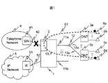
図1は本発明が適用されるブロードバンドアクセス網の構成例であり、本発明の効果である網障害時の電話サービス継続を示している。同図では電話交換網4とOLT(Optical Line Terminator)1間の回線42に障害が発生した場合にも電話接続サービスを継続する例を示している。
FIG. 1 is a configuration example of a broadband access network to which the present invention is applied, and shows continuation of telephone service when a network failure is an effect of the present invention. The figure shows an example in which a telephone connection service is continued even when a failure occurs in a
ブロードバンドアクセス網内に設置するOLT1は光ファイバ11a、光信号を分岐・多重するスプリッタ12、光ファイバ13a〜13bを介して加入者宅に設置するONT(Optical Network Terminal)3a〜3dを収容する。また、OLT1は回線42を介して電話交換網4内の電話交換機41と接続し、回線52を介してIPネットワーク5内のルータ51と接続している。2はOLTと電話交換網4内の電話交換機41とを接続するVoiceゲートウェイ(以下VGW)を示している。ONT3aは加入者電話6a〜6b、ONT3bは電話機6c〜6dをそれぞれ収容している。61は通話音声データの流れを示しており、回線42に障害が発生し、OLT1と電話交換網4との接続が失われた場合に、VGW2を介して電話機6aと電話機6d間で通話している例を示している。
The
図2は本発明が適用されるブロードバンドアクセス網において、障害が発生していない正常な状況における電話サービスの実施例を示している。図2で示す網構成は図1と同様であり、差分は図2の62でしめす正常時の通話音声の流れと図1の61で示す網障害時の通話音声データの流れである。正常時の通話音声データは、発呼元加入者、発呼先加入者が共OLT1に接続されたONTに接続した電話機を利用している場合においても電話交換機41を介して交換される。つまり、VGW2はシグナリングおよび伝送音声フォーマットを変換する機能を持つゲートウェイであり、電話交換機相当の交換や三者間通話等の付加サービス提供機能を持つ必要がない。
FIG. 2 shows an embodiment of a telephone service in a normal situation where no failure occurs in the broadband access network to which the present invention is applied. The network configuration shown in FIG. 2 is the same as that shown in FIG. 1, and the difference is the flow of call voice during normal operation indicated by 62 in FIG. 2 and the flow of call voice data when a network failure is indicated by 61 in FIG. Normal call voice data is exchanged via the
図3の1は本発明のVGW機能を持つOLTの構成例であり、VGW機能2、パケットインタフェース15、PONインタフェース14a〜14b、ONTからのデータパケットを多重化する機能を持つパケットスイッチ16で構成する。VGW2は回線42を介して電話交換網と接続し、パケットインタフェース15は回線52を介してIP網に接続する。各PONインタフェース14a〜14bは複数のONT3a〜3dを収容する。同図ではPONインタフェース14aがONT3a〜3bを回線13a〜13b、スプリッタ12、回線11aを介して収容している。VGW2と各ONT間にはシグナリングメッセージと通話音声データを送受信するためのPoint−to−Point回線である論理パスを設定する。同図ではVGW2とONT3a間に論理パス71a、VGW2とONT3b間に論理パス71bを設定している。これらの論理パスを用いてVGW2と各ONTとの通信を実施する。
3 is an example of a configuration of an OLT having a VGW function according to the present invention, which includes a
図4はパケットスイッチ16で使用するパケットフォーマットの一例として、IEEE802.3で規定されるイーサネットフレームを示している。イーサネットフレームは6バイトの宛先アドレス(DA)1681、6バイトの送信元アドレス(SA)1682、タグ情報の使用を示す2バイトのTag Protocol ID(TPID)1688、4ビットの転送優先値(P)1687、12ビットのTag値(Tag)1686、2バイトのパケットタイプ値またはパケット長値(L/T)1683、46〜1500バイトのペイロード1684、4バイトのFrame Check Sequence(FCS)1685から構成される。本実施例ではTag値1686を論理パスIDとしてIVG2と各ONT間で論理パスを構成する。
FIG. 4 shows an Ethernet frame defined by IEEE 802.3 as an example of a packet format used in the
図5はONT、VGW機能を含むOLT、電話交換機のプロトコルスタック構成図である。(a)は制御プレーンのプロトコルスタック、(b)はデータプレーンのプロトコルスタックを示している。(a)制御プレーンにおいて、ONTの回線インタフェースはPONレイヤ397、イーサネットレイヤ396、IPレイヤ395、UDPレイヤ394を持ち、その上位にシグナリングプロトコルとしてH.248とSIP(391)、RFC2833(393)を持つ。OLT内では、PONインタフェースでPONレイヤ148によってカプセル化されたイーサネットフレームとイーサネット149を相互に変換し、パケットスイッチがイーサネット169でPONインタフェースとVGWを接続する。VGWはパケットスイッチ側にONTと同様に、イーサネットレイヤ299、IPレイヤ298、UDPレイヤ297を持ち、その上位にシグナリングプロトコルとしてH.248とSIP(294)、RFC2833(295)を持つ。VGWは電話交換機側にDS1等のTDMレイヤ291とシグナリングプロトコルであるGR303レイヤ292を持つ。さらにVGWはパケットスイッチ側と電話交換機側のシグナリングプロトコルを相互に変換するInter−Work機能293を持つ。電話交換機はデータ転送を行うTDMレイヤ419とシグナリングプロトコルであるGR303レイヤ418を持つ。
(b)データプレーンにおいては、ONTの回線インタフェースはPONレイヤ397、イーサネットレイヤ396、IPレイヤ395、UDPレイヤ394、RTP(Real Time Transport Protocol)レイヤ393を持つ。OLT内では、PONインタフェースでPONプロトコル148によってカプセル化されたイーサネットフレームとイーサネット149を相互に変換し、パケットスイッチがイーサネット169でPONインタフェースとVGWを接続する。VGWはパケットスイッチ側にONTと同様に、イーサネット299、IP298、UDP297、RTP296を持ち、その上位に転送データをパケットスイッチ側のイーサフレーム形式と電話交換機側のTDM形式間で相互に変換する機能を持つTDM−パケット変換機能281を持つ。VGWは電話交換機側にはDS1等のTDMレイヤ291を持つ。電話交換機も同様にTDMレイヤ419を持つ。
FIG. 5 is a protocol stack configuration diagram of the ONT, the OLT including the VGW function, and the telephone exchange. (A) shows the protocol stack of the control plane, and (b) shows the protocol stack of the data plane. (A) In the control plane, the ONT line interface has a
(B) In the data plane, the ONT line interface has a
図6はVGW2の構成を示している。VGW2は電話交換機と接続する回線を収容するTDMインタフェース22、パケットスイッチと接続するパケットインタフェース23、タイムスロット間の接続制御を行うTSI(Time Slot Interchange)24、TDM-パケット変換機能25、トーン生成機能26、CPU・Memory部21により構成する。TSI24はTDM−パケット変換機能25とTDMインタフェース22を接続し、TDM−パケット変換機能25はパケットインタフェース23と接続する。トーン生成機能26は電話呼制御に必要となるトーンを生成する機能であり、本実施例では後述の障害発生時に維持した呼の解放動作時に使用する。TDMインタフェース22、TSI24、トーン生成機能26、TDM−パケット変換機能25、パケットインタフェース23のそれぞれはCPU・Memory部21と接続し、CPU・Memory部から制御可能である。
FIG. 6 shows the configuration of the
パケットインタフェース23はARP情報238、MAC−パス情報239を持つ。図10に示すように、ARP情報238はONTのIPアドレスと該当するONTのMACアドレスとVGW機能とONT間の論理パスのIDを対応付ける情報である。また、図9に示すように、MAC−パス情報239はONTのMACアドレスとVGWと該当するONTを接続する論理パスのIDを関連付ける情報である。VGWはこれらの情報を用いてONTに対してパケットを送信する。各ONTのIPアドレスはONTの登録時に管理者が設定し、ARP情報238に登録する。VGWと各ONT間の論理パスもONTの登録時に設定し、該当ONTのIPアドレスと関連付けてARP情報238に登録する。ARP情報238に登録する各ONTのMACアドレスは、VGWがARPプロトコル(RFC826)を用いて各ONTから取得するか、管理者が設定する。以上の手続きでARP情報238が完成する。この情報の内MACアドレスと論理パスIDの対応情報がMAC−パス情報239である。
The
VGWからONTへIPパケットを転送する場合、VGWはARP情報を用いて宛先ONTのMACアドレスと宛先ONTまでの論理パスIDを検出し、パケットを転送する。また、VGWは電話交換網の障害時にMAC−パス情報を用いてONT間の通信を実現する。MAC−パス情報を用いたONT間通信の詳細は後述する。 When transferring an IP packet from the VGW to the ONT, the VGW uses the ARP information to detect the MAC address of the destination ONT and the logical path ID to the destination ONT, and transfers the packet. Further, the VGW realizes communication between the ONTs using the MAC-path information when the telephone switching network fails. Details of the ONT communication using the MAC-path information will be described later.
CPU・Memory部21にはGR303によるTDMシグナリング機能211、H.248、SIPによるパケットシグナリング機能212、TDMシグナリング機能211とパケットシグナリング機能212を接続する機能を持つInter−work機能213をソフトウェアで実装する。VGWは、Inter−Work機能213で加入者電話機の電話番号情報であるディレクトリ情報218と通話中の呼に関する情報であるActive Call情報219を持つことによって、障害が発生したときの通話呼の維持、および、障害発生以後の新規呼の接続サービスを実現する。
The CPU /
図7に示すように、ディレクトリ情報218は加入者電話を収容する電話線(POTSライン)ごとに付けられる識別子であるCRV(Call Reference Value)、POTSライン識別名称、電話番号(ディレクトリ番号)、POTSラインの属するONTのIPアドレスを関連付ける情報である。また、図8に示すように、Active Call情報219は発呼元(Caller)加入者情報と発呼先(Callee)加入者情報を関連付ける情報である。発呼元加入者情報と発呼先加入者情報はそれぞれ該当加入者電話が属する電話回線に付けられる識別子であるCRV、POTSライン名称、VGWと交換機間のTDM回線で用いるタイムスロット番号、VGWと該当加入者が属するONT間のRTPセッション情報を含む。
As shown in FIG. 7, the
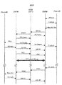
図11は発呼時の加入者、ONT、VGW、電話交換機間でのシグナリング情報の交換を示したシーケンス図である。ここではONTとVGW間のシグナリングプロトコルとしてH.248とRFC2833を使用している。以下、同図を説明する。まず、加入者が電話機の受話器を取るとONTが電話機のOff−Hookイベントを検出する。Off−Hookイベントを検出したONTは、H.248のNOTIFY RequestメッセージによってOff−HookイベントをVGWに通知する。VGWはNOTIFY Request(Off−Hook)メッセージを受けるとGR303のSETUPメッセージを交換機に送信し、H.248 NOTIFY ReplyメッセージをONTに送信する。GR303 SETUPを正常に受付けた交換機はGR303 CONNECTメッセージをVGWに送信する。GR303 CONNECTメッセージを受信したVGWはH.248 ADD RequestメッセージをONTに送信し、ONTに通話データ送受信の端点生成(RTPセッション生成)を指示する。H.248 ADDメッセージを正常に処理したONTはADD ReplyをVGWに送信し、音声データをVGWと送受するためのRTPセッションを確立する。H.248 ADD Replyメッセージを受信したVGWは、交換機との通信に用いるタイムスロットを割当て、GR303 CONNECT ACKメッセージを交換機に送信する。さらに、ONTと音声データを送受するRTPセッションを確立する。そして、タイムスロットとRTPセッション間の関連付けをTDM−パケット変換機能に行う。ONTはRTPセッションを確立するとそのRTPセッションを用いてRFC2833のOff−HookイベントメッセージをVGWに送信する。このRFC2833メッセージ(Off−Hook)を受信したVGWは、GR303で規定されるABCD Robbed Bit Signaling方式でLoop Closureイベントを交換機に通知する。以上の手続きにより、交換機と加入者電話間の音声チャネルが確立する。 FIG. 11 is a sequence diagram showing the exchange of signaling information among subscribers, ONTs, VGWs, and telephone exchanges when making a call. Here, H.264 is used as a signaling protocol between ONT and VGW. 248 and RFC2833 are used. The figure will be described below. First, when the subscriber picks up the telephone handset, the ONT detects the telephone's Off-Hook event. The ONT that detects the Off-Hook event is H.264. An off-hook event is notified to the VGW by a 248 NOTIFY Request message. When the VGW receives a NOTIFY Request (Off-Hook) message, it sends a GR303 SETUP message to the exchange. 248 Send NOTIFY Reply message to ONT. The exchange that has normally accepted the GR303 SETUP transmits a GR303 CONNECT message to the VGW. The VGW that has received the GR303 CONNECT message is H.264. A 248 ADD Request message is transmitted to the ONT, and the ONT is instructed to generate endpoints for transmitting / receiving call data (RTP session generation). H. The ONT that has successfully processed the 248 ADD message sends an ADD Reply to the VGW and establishes an RTP session for sending and receiving voice data to and from the VGW. H. The VGW that has received the 248 ADD Reply message allocates a time slot to be used for communication with the exchange and transmits a GR303 CONNECT ACK message to the exchange. Further, an RTP session for transmitting and receiving ONT and voice data is established. Then, the association between the time slot and the RTP session is performed to the TDM-packet conversion function. When the ONT establishes the RTP session, the RTP session is used to send an RFC2833 Off-Hook event message to the VGW. The VGW that has received this RFC2833 message (Off-Hook) notifies the exchange of a Loop Close event using the ABCD Robbed Bit Signaling method defined by GR303. The above procedure establishes a voice channel between the exchange and the subscriber telephone.
続いて、電話交換機は確立した交換機とONT間の音声チャネルを用いて加入者電話機にダイヤルトーンを送信する。ダイヤルトーンを認識した加入者は、通話先の電話番号を電話機に入力する。この電話番号情報は音声チャネルを用いてDTMF(Dual Tone Multi Frequency)トーンで交換機に伝達される。通常のVGWは電話番号の管理に関与しないため、このDTMFトーン情報を音声データとして交換機に対して中継する。本発明のVGWはこのDTMFトーンを中継時に捕捉することおよび図12のプロトコルシーケンス図を用いて説明する着呼処理時にローカルコール(発呼元、発呼先ONTが共に該当OLT(VGW)に接続されている)であることを検出する仕組みによって、加入者電話間の通話状態を保持するActive Call情報を作成する。Active Call情報の作成手順は図13のフローチャートを用いて後述する。 Subsequently, the telephone exchange transmits a dial tone to the subscriber telephone using a voice channel between the established exchange and the ONT. The subscriber who has recognized the dial tone inputs the telephone number of the other party to the telephone. This telephone number information is transmitted to the exchange with a DTMF (Dual Tone Multi Frequency) tone using a voice channel. Since a normal VGW is not involved in the management of telephone numbers, this DTMF tone information is relayed to the exchange as voice data. The VGW according to the present invention captures this DTMF tone at the time of relaying, and at the time of incoming call processing described with reference to the protocol sequence diagram of FIG. 12, both the call source and the call destination ONT are connected to the corresponding OLT (VGW). Active Call information that holds a call state between subscriber telephones is created by a mechanism for detecting that the call has been made. The procedure for creating Active Call information will be described later with reference to the flowchart of FIG.
続いて、DTMFトーンによって通話先の電話番号を受け取った電話交換機は電話交換網を介して通話先電話機までの音声チャネルを確立する。通話先加入者が電話機の受話器を取るまでの間、電話交換網からはRingbackトーンが発呼元電話機に対して送られる。 Subsequently, the telephone exchange that has received the telephone number of the callee by the DTMF tone establishes a voice channel to the callee telephone via the telephone exchange network. Until the called subscriber picks up the telephone handset, a ringback tone is sent from the telephone switching network to the calling telephone.
なお、図11では電話番号情報をDTMFトーンで伝達する方式を示したが、電話番号情報をRFC2833等のパケットメッセージによって伝達する方式もある。図26はRFC2833のメッセージを用いて電話番号情報を伝達する方式を示している。IPネットワークのパケットロスや遅延が大きい環境においてはRTPの音情報として伝達されるDTMFトーンが受信側で正確に再生できない場合がある。このような環境においてはRFC2833メッセージが用いられる。 Although FIG. 11 shows a system for transmitting telephone number information using DTMF tones, there is also a system for transmitting telephone number information by a packet message such as RFC2833. FIG. 26 shows a method of transmitting telephone number information using an RFC2833 message. In an environment where the packet loss and delay of an IP network are large, there are cases where the DTMF tone transmitted as RTP sound information cannot be accurately reproduced on the receiving side. In such an environment, an RFC2833 message is used.
次に、図12は発呼先加入者に対する着呼時の電話交換機、VGW、ONT、加入者間でのシグナリング情報の交換を示したシーケンス図である。以下、同図を説明する。まず、VGWが交換機からGR303 SETUPメッセージを受信する。本発明のVGWはこのメッセージに含まれる着呼加入者を示すCRVによりActive Call情報を検索する。この呼の発呼元電話機が本VGWを収容するOLTに接続されたONTに属するものであれば、図11および図26で説明した発呼時の処理によってActive Call情報に登録したエントリに、同一のCRV情報を持つものがある。これによって本発明のVGWは発呼元と発呼先電話機がともにそのVGWに接続されたONTに属するローカルコールであることを認識する。SETUPメッセージを受信したVGWはONTに対してH.248 ADD Requestメッセージを送信し、通話データ送受の端点生成(RTPセッション確立)を要求する。ONTはADD Requestを受信するとADD ReplyをVGWに返信し、RTPセッションを確立する。ADD Replyを受信したVGWもRTPセッションを確立し、交換機にGR303 CONNECTメッセージを送信し、タイムスロットを割当てる。そして、タイムスロットとRTPセッション間の関連付けをTDM−パケット変換機能に行う。以上の手続きにより、交換機と加入者電話間の音声チャネルが確立する。 Next, FIG. 12 is a sequence diagram showing the exchange of signaling information among the telephone exchange, VGW, ONT, and subscriber at the time of an incoming call to the calling subscriber. The figure will be described below. First, the VGW receives a GR303 SETUP message from the exchange. The VGW of the present invention searches for the Active Call information by the CRV indicating the called subscriber included in this message. If the call source telephone of this call belongs to the ONT connected to the OLT that accommodates this VGW, it is the same as the entry registered in the Active Call information by the call processing described with reference to FIGS. Some have CRV information. As a result, the VGW of the present invention recognizes that both the caller and callee telephones are local calls belonging to the ONT connected to the VGW. The VGW that has received the SETUP message sends an H.264 message to the ONT. A 248 ADD Request message is transmitted to request end point generation (RTP session establishment) for call data transmission / reception. When the ONT receives the ADD Request, it returns an ADD Reply to the VGW and establishes an RTP session. The VGW that has received the ADD Reply also establishes an RTP session, transmits a GR303 CONNECT message to the exchange, and assigns a time slot. Then, the association between the time slot and the RTP session is performed to the TDM-packet conversion function. The above procedure establishes a voice channel between the exchange and the subscriber telephone.
続いて電話交換機はGR303で規定されるABCD Robbed Bit Signaling方式を用いて電話機で着信音を鳴らせるRing要求をVGWに通知する。これを受信したVGWはそのRing要求をRFC2833メッセージによってONTに通知し、ONTが電話機の着信音を鳴らす。発呼先加入者が電話機の受話器を取ると、ONTが電話機でOff−Hookイベントが発生したことを検出し、H.248 NOTIFY RequestメッセージによってOff−HookイベントをVGWに通知する。NOTIFY Requestメッセージを受信したVGWはNOTIFY ReplyメッセージをONTに返信する。ONTはさらにRFC2833のOff−HookイベントメッセージをVGWに送信する。RFC2833(Off−Hook)メッセージを受信したVGWは、ABCD Robbed Bit Signeling方式によってOff−Hookイベントを交換機に通知する。 Subsequently, the telephone exchange uses the ABCD Robbed Bit Signaling method defined by GR303 to notify the VGW of a Ring request for ringing a ring tone on the telephone. Receiving this, the VGW notifies the ring request to the ONT by the RFC2833 message, and the ONT rings the telephone ring tone. When the called subscriber picks up the telephone handset, the ONT detects that an Off-Hook event has occurred on the telephone; 248 Notifies the off-hook event to the VGW by a NOTIFY Request message. The VGW that has received the NOTIFY Request message returns a NOTIFY Reply message to the ONT. The ONT further sends an RFC2833 Off-Hook event message to the VGW. The VGW that has received the RFC2833 (Off-Hook) message notifies the switch of the Off-Hook event by the ABCD Robbed Bit Signaling method.
図13は図11、図12で説明したプロトコルシーケンスによる発呼処理と着呼処理においてVGWがActive Call情報を作成する手順を示すフローチャートである。以下、フローチャートに沿ってActive Call情報作成方式を説明する。加入者からの発呼時に、交換機との音声チャネルであるタイムスロットの確立とONTとの音声チャネルであるRTPセッションの確立に成功した時点から説明する。図11ではVGWがABCD Robbed Bit Signaling方式によってLoop Closureイベントを交換機に通知した時点である。 FIG. 13 is a flowchart showing a procedure in which the VGW creates Active Call information in the calling process and the incoming call process according to the protocol sequence described in FIGS. The Active Call information creation method will be described below with reference to the flowchart. A description will be given from the time when the establishment of a time slot, which is a voice channel with an exchange, and the establishment of an RTP session, which is a voice channel with an ONT, when a call is made from a subscriber. FIG. 11 shows a point in time when the VGW notifies the exchange of a Loop Close event by the ABCD Robbed Bit Signaling method.
タイムスロットとRTPセッションを確立(911)したVGWは音声チャネル監視モードとなり、ONTから交換機に送信される発呼先の電話番号情報であるDTMFトーンを監視する(912)。VGWはDTMFトーンを検出すると、検出した発呼先電話番号によってディレクトリ情報218を検索する(913)。ディレクトリ情報に該当電話番号が登録されていれば、発呼先の加入者もそのVGWの管理下に存在するローカルコールであるため、Active Call情報への登録処理を行う。まず、発呼者の情報をActive Call情報の発呼者(Caller)情報に登録する(915)。この登録に必要なCRV情報はONTからのNOTIFY Requestメッセージに含まれるPOTS回線名によってディレクトリ情報を検索することによって得られる。また、タイムスロットおよびRTPセッション情報は手続き911のタイムスロットとRTPセッション確立の際に得られる情報である。次に、発呼先の電話番号に関するエントリを発呼先(Callee)情報としてActive Call情報219に登録する(916)。なお、この時点では、発呼先ONTとVGW間で設定するRTPセッションとVGWと交換機間のタイムスロットは未確立のため、Active Call情報の通話先情報のタイムスロット情報とRTPセッション情報は空欄となる。ここで呼処理中の呼はVGW配下のローカルコールのため、交換機は折返し通信のためにVGWに対して着呼処理を行うことになる。したがって、VGWはローカルコールの着呼待ち状態になる(917)ことによってこの着呼処理を検出する。VGWは交換機からSETUPメッセージを受信すると、SETUPメッセージに含まれるCRVによりActive Call情報を検索し、ローカルコールを検出する。ローカルコールを検出すると、着呼用に割当てた(919)タイムスロット情報とRTCセッション情報をActive Call情報に登録する(920)。以上によってActive Call情報が完成する。
The VGW that established the time slot and RTP session (911) enters the voice channel monitoring mode, and monitors the DTMF tone, which is the telephone number information of the call destination transmitted from the ONT to the exchange (912). When the VGW detects the DTMF tone, the VGW searches the
以下では障害発生時のVGWによる通話中呼の維持方式を説明する。VGW2は図1に示す電話交換機41または電話交換機41とVGWを繋ぐ回線42の障害を回線42で受信するエラー信号またはデータの異常によって検出する。VGW2は障害を検出すると、図6に24で示すTSIでローカルコールの通話者間のタイムスロットを接続することにより通話音声データを折り返す。各通話者が利用しているタイムスロットはActive Call情報219にタイムスロット情報として記録している。図14にタイムスロットの折返し接続の様子を示す。(A)は正常時のタイムスロットの正常運用時の設定状態を示している。24で示すTSIがタイムスロットチャネル241とタイムスロットチャネル242をTDM−パケット変換機能25とTDMインタフェース22間で中継している状態を示している。タイムスロットチャネル241と242はそれぞれ全二重チャネルであり、タイムスロットチャネル241ではTDM−パケット変換機能からのビット列が2411で示され、TDM−パケット変換機能へのビット列が2412で示されている。同様に、タイムスロットチャネル242ではTDM−パケット変換機能からのビット列が2421で示され、TDM−パケット変換機能へのビット列が2422で示されている。
(B)は障害発生時に24で示すTSIでタイムスロットチャネルを操作し、ローカルコールの発呼元と発呼先の通話を折返し接続する場合の設定状態を示している。同図ではタイムスロットチャネル241とタイムスロットチャネル242を接続している。図1に示すように電話機6aと6d間で通話が行われているとする。また、電話機6aと交換機41間の通話音声データ転送はタイムスロットチャネル241を使用し、電話機6dと交換機41間の通話音声データはタイムスロット242を使用しているとする。この場合、障害発生時に図14(B)に示すようにTSI24がタイムスロットチャネル241と242を接続し、ビット列2411をビット列2422へ、ビット列2421をビット列2412に折返し転送することによって、電話機6aからの通話音声を電話機6dに折り返し、かつ、電話機6dからの通話音声を電話機6aに折り返す。以上の処理によって、障害発生時においてもVGWは通話中の呼を維持することができる。
Hereinafter, a method for maintaining a call during a call by the VGW when a failure occurs will be described. The
(B) shows the setting state when the time slot channel is operated with the TSI indicated by 24 when a failure occurs, and the call of the local call source and the call destination are connected back. In the figure, a
なお、ローカルコール以外の呼が使用していたタイムスロットは、障害発生時に全て解放する。 All time slots used by calls other than local calls are released when a failure occurs.
次に図15と図16を用いて、維持した呼の解放処理について述べる。図15は加入者が電話機#1で会話を終えて受話器を置いた時のプロトコル処理を示すシーケンス図である。電話機#1で受話器が置かれるとONTが電話機のOn−Hookイベントを検出する。On−Hookイベントを検出したONTはH.248 NOTIFY RequestメッセージをVGWに送る。このメッセージを受信したVGWはH.248 NOTIFY ReplyメッセージをONTに返信すると同時に図16に示す通話の相手側の電話機#2に対する切断プロトコル処理を起動する。図16に関しては後述する。上述のH.248 NOTIFY Replyメッセージを受信したONTはRFC2833のOn−HookイベントメッセージをVGWに送信する。VGWはONTからのRFC2833(Oh−Hook)イベントメッセージを受信すると、H.248 Subtract RequestメッセージをONTに送信する。このメッセージを受信したONTはH.248 Subtract ReplyメッセージをVGWに返送し、RTPセッションを解放する。H.248 Subtract Replyメッセージを受信したVGWもRTPセッションを解放し、ONTの該当POTS回線を初期化するためのH.248 Modify RequestメッセージをONTに送信する。このメッセージを受信したONTは該当POTS回線を初期化し、新規の呼接続が可能な状態となり、H.248 Modify ReplyメッセージをVGWに返信する。
Next, the maintained call release processing will be described with reference to FIGS. 15 and 16. FIG. 15 is a sequence diagram showing protocol processing when the subscriber finishes the conversation with the
次に図16で示す通話の相手側の電話機#2に対する切断プロトコル処理を説明する。前述のように電話機#1のOn−Hookイベントを契機としてVGWは電話機#2の属するONTに対してRFC2833のLCFO(Line Current Feed Open)メッセージを送信する。このメッセージを受信したONTは該当POTSラインをLCFO状態とし、電話機#2に対して電話機#1がOn−Hookとなったことを通知する。さらにVGWは図6の26で示すトーン生成機能を用いて電話機#2にビジートーンを送る。ビジートーンを聞いた加入者は電話機#2の受話器を置く。これによって電話機#2がOn−HookイベントをONTに通知し、ONTはH.248 NOTIFY RequestメッセージによってOn−HookイベントをVGWに通知する。このメッセージを受信したVGWはNOTIFY ReplyをONTに返送する。さらにONTはRFC2833のOn−HookメッセージをVGWに送信する。VGWはONTからのRFC2833(Oh−Hook)イベントメッセージを受信すると、H.248 Subtract RequestメッセージをONTに送信する。このメッセージを受信したONTはH.248 Subtract ReplyメッセージをVGWに返送し、RTPセッションを解放する。H.248 Subtract Replyメッセージを受信したVGWもRTPセッションを解放し、ONTの該当POTS回線を初期化するためのH.248 Modify RequestメッセージをONTに送信する。このメッセージを受信したONTは該当POTS回線を初期化し、新規の呼接続が可能な状態となり、H.248 Modify ReplyメッセージをVGWに返信する。
Next, the disconnection protocol processing for the
図17は上述の呼切断時のActive Call情報の削除手順およびリソース開放手順を示したフローチャートである。H.248 NOTIFY Requestメッセージによって加入者によるOn−Hookイベントを検出したVGWは(931)、そのメッセージに含まれるPOTSライン名によってActive Call情報のCalee情報を検索し(932)、Calee登録があれば(933)、該当エントリを削除する(934)。さらに、図14の24で示すTSIにおいて使用している該当呼に関するタイムスロットを開放し(935)、また、RTPセッションを開放し(936)、処理を終了する(937)。Calee登録が無い場合(933)は障害発生時に解放されたローカルコール以外の呼に関するRTPセッションが残留していることが考えられるため、RTPセッションを開放し(936)、処理を終了する(937)。VGWは、以上の処理によって障害発生時に維持した通話中の呼の切断処理を行う。 FIG. 17 is a flowchart showing the procedure for deleting the Active Call information and the resource releasing procedure when the call is disconnected. H. The VGW that detected the On-Hook event by the subscriber by the 248 NOTIFY Request message (931) searches the Call information of the Active Call information by the POTS line name included in the message (932), and if there is a Care registration (933) ), The corresponding entry is deleted (934). Further, the time slot relating to the corresponding call used in TSI indicated by 24 in FIG. 14 is released (935), the RTP session is released (936), and the process is terminated (937). When there is no Caree registration (933), it is considered that an RTP session related to a call other than the local call released at the time of failure occurs, so the RTP session is released (936), and the process is terminated (937). . The VGW performs call disconnection processing during a call maintained at the time of failure by the above processing.
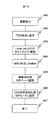
図18は電話交換網における障害発生時のVGWの障害対応処理全体を示すフローチャートである。上述の通り、障害を検出したVGWは(941)、ローカルコールのタイムスロットの折り返し設定を行い(942)、ローカルコール以外のタイムスロットを開放する(943)。さらに、新規の通話を扱うために次の手続きを行う。まず、図6の23で示すパケットインタフェース部の折り返し処理を有効にする(944)。次に図6の212で示すSIPサーバを起動する(945)。そして最後にONTをSIP動作モードに切り替えるメッセージを全ONTにブロードキャストし(946)、手続きを終了する(947)。以下で折り返し処理の有効化とONTのSIP動作モードへの切り替え手続きのそれぞれを順に説明する。 FIG. 18 is a flowchart showing the entire VGW failure handling process when a failure occurs in the telephone exchange network. As described above, the VGW that detects the failure (941) sets the return of the time slot of the local call (942), and releases the time slot other than the local call (943). In addition, the following procedure is performed to handle a new call. First, the return processing of the packet interface unit indicated by 23 in FIG. 6 is enabled (944). Next, the SIP server indicated by 212 in FIG. 6 is activated (945). Finally, a message for switching the ONT to the SIP operation mode is broadcast to all ONTs (946), and the procedure is terminated (947). Each of the procedure for enabling the return processing and switching to the SIP operation mode of the ONT will be described in turn below.
障害発生以後の新規呼の通話はパケットインタフェース部23で折り返すことになる。図19で示すように、パケットインタフェース23は論理パス71aと71bを収容しているとする。図3に示すように、論理パス71aはONT3aと接続しており、論理パス71bはONT3bと接続しているとする。ONT3aに属する加入者からONT3bに属する加入者への通話音声パケットは次のようにパケットインタフェース部23で折り返す。
A new call after the failure occurs is returned by the
まず、パケットインタフェース部23は、ONTのIPアドレスとMACアドレスの対応情報であるARP情報238を持つ。障害発生後、VGWはONTから送られてくる他のONTのMACアドレスの通知を要求するARP要求に対して代理返答する。例えば、ONT3aがONT3bに対してIPパケットを送る場合、ONT3aはONT3bのMACアドレスを知るためにONT3bのIPアドレスをMACアドレスに変換する要求であるARP要求を送信する。MACアドレスはOLT内のパケットスイッチで使用するイーサネットフレームの生成に必要である。VGWはこのARP要求を受信すると、ONT3bの代理としてONT3bのMACアドレスを返答する。この際のONTのIPアドレスとMACアドレスの対応付けにはARP情報238を用いる。
First, the
次にパケットインタフェース部23は、ONTのMACアドレスとパスの対応情報であるMAC−パス情報239を用いてONTからのイーサネットフレームを折返し転送する。例えば、パケットインタフェース部23は、ONT3aから論理パス71aを介してイーサネットフレームを受信すると、イーサネットフレームの宛先アドレスでMAC−パス情報を検索し、宛先MACアドレスに対応するパスIDを得る。このパスIDはONT3bと接続している論理パスのIDであり、この論理パスにイーサネットフレームを転送することによってONT3bへイーサネットフレームを転送する。
Next, the
なお、ONTからのSIPサーバ宛のIPパケットはVGW宛であり、そのMACアドレスはVGWに固有のものである。したがって、VGW宛MACアドレスを持つイーサネットフレームはVGWが受信し、CPU・Memory部21に転送する。
Note that the IP packet addressed to the SIP server from the ONT is addressed to the VGW, and its MAC address is unique to the VGW. Accordingly, the Ethernet frame having the MAC address addressed to the VGW is received by the VGW and transferred to the CPU /
図20は本発明で用いるONT3の構成例を示す図である。ONTはPONインタフェース32、パケットスイッチ33、音声データパケットと音声を相互変換する機能を持つDSP(Digital Signal Processor)34、POTSラインを介して電話機6e〜6fを収容するSLIC(Serial Lie Interface Circuit)36、加入者のLAN(Local Area Network)39を収容するパケットインタフェース35、プロトコル処理を行うCPU・メモリ部31で構成する。CPU・メモリ部31ではシグナリング機能であるであるH.248クライアント機能312とSIPクライアント機能311を持つ。さらに、H.248とSIPのどちらを用いるかをVGWからの指示にしたがって切り替える機能を持つプロトコルセレクタ313を持つ。これらのシグナリング機能およびプロトコルセレクタ機能はソフトウェアによって実装する。
FIG. 20 is a diagram showing a configuration example of the ONT 3 used in the present invention. The ONT includes a
図20ではONT3が使用する論理パス71、72、79を示している。パス71は本ONTとVGW間の通信で用いる論理パスである。論理パス72は本ONTと図3の15で示すOLTのパケットインタフェース間の通信で用いる論理パスであり、IP網5との通信に利用する。論理パス79はVGWからのプロトコルセレクタ機能313に対する指示を受信するための論理パスである。図21は2で示すVGWが複数のONT3a〜3bに対してシグナリングプロトコルを正常時に使用するH.248から障害発生時に使用するSIPに切り替える制御メッセージを送信するために用いる論理パス79を示している。論理パス79はVGW2とONT3a〜3b間に対して設定するマルチキャストパスであり、VGW2はこのパスを用いて制御メッセージを全ONTにブロードキャストすることにより、多数のONTを同時に制御する。このマルチキャストパスを用いたブロードキャストでは、まず、VGW2が送信した制御情報をパケットスイッチ79が各PONインタフェース14a〜14bに対してコピーする。次に、各PONインタフェースが転送する制御メッセージは、スプリッタ11aによって光信号レベルでコピーされ、各ONTに配信される。
FIG. 20 shows
図22はVGW配下の電話機#1が同じくそのVGWに属する電話機#2に対して電話する際のSIPプロトコルシーケンスおよび通話を終了するSIPプロトコルシーケンスを示す図である。電話機#1のOff−Hookイベントを検出したONT#1はダイヤルトーンを電話機#1に対して伝達する。ダイヤルトーンを聞いた電話機#1の加入者は通話先の電話番号を電話機#1に入力する。ONT#1は受け取った電話番号をINVITEメッセージによってVGWに送信する。VGWのSIPサーバ機能はディレクトリ情報218を検索し、その電話番号に対応するONTのIPアドレスを検出し、INVITEメッセージを該当するONT#2に送信する。VGW、ONT#2はINVITEメッセージを受けるとそれぞれが呼処理継続中を意味する100 TryingメッセージをONT#1、VGWに返信する。INVITEメッセージを受信したONT#2は電話機#2で着信音(Ring)を発生させ、同時に着信音発生中であることを示す180 RingingメッセージをVGWに送信し、VGWはそのメッセージをONT#1に転送し、ONT#1は電話機#1にRingbackトーンを伝達する。電話機#2の加入者が受話器を取ると電話機#2のOff−Hookイベントを検出したONT#2が200 OKメッセージおよびACKメッセージをVGWに送信する。VGWはそれらのメッセージをONT#1に転送する。以上の処理が終了後、ONT#1とONT#2間のRTPセッションを確立する。RTPセッションはONT#1とONT#2間のセッションであり、このセッションに属するRTPデータはパケットインタフェース部23によって前述の通りイーサネットフレームレベルで折返し転送する。
FIG. 22 is a diagram showing a SIP protocol sequence when the
引き続き図22を用いて通話の終了時の呼開放プロトコルシーケンスを説明する。電話機#1の加入者が受話器を置くと、On−Hookイベントを検出したONT#1がBYE3メッセージをVGWに送信し、VGWがそのメッセージをONT#2に転送し、ONT#2がBusyトーンを電話機#2に伝達する。電話機#2の加入者が受話器を置くとOn−Hookイベントを検出したONT#2が200 OKメッセージをVGWに送り、VGWがそのメッセージをONT#1に転送する。
The call release protocol sequence at the end of the call will be described with reference to FIG. When the subscriber of
第1の実施例のVoiceゲートウェイは、電話交換網側の障害発生時において、OLTに接続されたONTに属する電話機間での通話中の呼維持と、ONTに属する電話機間での新規の呼接続を実施することが出来る。 The Voice gateway of the first embodiment maintains a call during a call between telephones belonging to the ONT connected to the OLT and a new call connection between the telephones belonging to the ONT when a failure occurs on the telephone switching network side. Can be implemented.
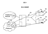
図23は本発明の第二の実施例を示している。第二の実施例は、SIPサーバ機能をVGW1内でなく、IP網5内のSIPサーバ59で実現することを特徴とする。図24の69はONT3aに属する電話機6aとONT3bに属する電話機6d間の通話音声データの流れを示している。ここでは、通話音声はIP網5内で折り返される。このため図23で示すように、OLTのパケットインタフェース15と各ONT3a〜3b間で通話音声データを転送する論理パスを設定する。同図ではパケットインタフェース15とONT3a間に論理パス72aを設定し、パケットインタフェース15とONT3b間に論理パス72bを設定する例を示している。この論理パスを用いてパケットインタフェースからONTへパケット転送するために、OLTのパケットインタフェース15にMAC−パス情報159を置く。MAC−パス情報は図9で示すように、第一の実施例でVGWが持つMAC−パス情報239と同様の情報を持つ。ONTのMACアドレスと論理パスIDの対応はパス設定時の初期設定によって行う。
FIG. 23 shows a second embodiment of the present invention. The second embodiment is characterized in that the SIP server function is realized not by the
図25は障害発生時のVGWの障害対応モードへの移行処理を示すフローチャートである。電話交換網の障害を検出したVGWは(951)、ローカルコールのタイムスロットの折り返し設定を行い(952)、ローカルコール以外のタイムスロットを開放する(953)。さらに、新規の通話を扱うために次の手続きを行う。まず、図23で示すパケットインタフェース15と各ONT間の論理パス72a〜72bを設定する(954)。次に障害時用のSIPサーバ59を起動する(955)。そして最後に図21で示すマルチキャスト論理パスを用いてONTをSIP動作モードに切り替えるメッセージを全ONTにブロードキャストしてSIPクライアントを起動し(957)、さらに、使用する全ONTにSIPサーバ59のアドレスを通知し(958)、処理を終了する(959)。なお、既に他のVoIP(Voice Over IP)サービス用にSIPサーバ59が動作している場合、障害時用に新規サーバを起動せず、起動済みのSIPサーバを利用することも出来る。
FIG. 25 is a flowchart showing the transition process of the VGW to the failure handling mode when a failure occurs. The VGW that has detected a failure in the telephone exchange network (951) performs loopback setting of the local call time slot (952), and releases time slots other than the local call (953). In addition, the following procedure is performed to handle a new call. First,
第2の実施例のVoiceゲートウェイは、電話交換網側の障害発生時において、OLTに接続されたONTに属する電話機間での新規の呼接続を実施することが出来る。 The Voice gateway of the second embodiment can perform a new call connection between telephones belonging to the ONT connected to the OLT when a failure occurs on the telephone switching network side.
1…OLT(Optical Line Terminator)、2…Voice Gateway、3a、3b…ONT(Optical Network Terminal)、4…電話交換網、5…IP網、6a〜6d…電話機、15…OLTのパケットインタフェース、16…OLT内パケットスイッチ、14a〜14b…PONインタフェース、12…スプリッタ、22…TDMインタフェース、23…TSI(Time Slot Interchange)、26…トーン生成機、25…TDM−パケット変換機能、23…VGWのパケットインタフェース、21…VGWのCPU・メモリ部。
DESCRIPTION OF
Claims (21)
前記OLTは、
前記ONTに接続される前記電話機の電話番号情報を記憶する記憶部を備え、
前記ONTに接続される発呼元電話機から前記電話交換網内の電話交換機に対して送信される音声データの発呼先電話機の電話番号情報を捕捉し、
前記捕捉した発呼先電話機の電話番号情報が前記電話番号情報に記憶されている場合に、
前記電話交換機と前記発呼先電話機間の通話チャネル情報と前記発呼元電話機と前記電話交換機間の通話チャネル情報とを対応づけて記録し、
前記電話交換網内で障害発生が検出された場合に、前記二つの通話チャネル情報を用いて前記発呼元電話機と前記発呼先電話機間の通話チャネルを接続し、前記電話交換網を介することなく前記発呼元電話機と前記発呼先電話機間の通話を継続することを特徴とするPONシステム。 A Passive Optical Network (PON) system including a plurality of ONTs (Optical Network Terminals) in which telephones are accommodated and OLTs (Optical Line Terminals) having a gateway function and connected to a telephone exchange network,
The OLT is
A storage unit for storing telephone number information of the telephone connected to the ONT;
Capturing telephone number information of the calling destination telephone voice data to be transmitted to the telephone exchange of said telephone network from the calling telephone to be connected to the ONT,
When the telephone number information of the captured call destination telephone is stored in the telephone number information,
The call channel information between the telephone exchange and the call destination telephone and the call channel information between the caller telephone and the telephone exchange are recorded in association with each other,
When a failure occurrence is detected in the telephone exchange network, the call channel between the caller telephone and the callee telephone is connected using the two call channel information, and the telephone exchange network is used. A PON system that continues a call between the caller telephone and the callee telephone.
前記発呼先電話機に対する前記電話交換機からの着信を捕捉し、前記電話交換機と前記発呼先電話機間の通話チャネル情報と前記発呼元電話機と前記電話交換機間の通話チャネル情報とを対応づけて記録し、
前記電話交換網内で障害発生が検出された場合に、前記二つの通話チャネル情報を用いて前記発呼元電話機と前記発呼先電話機間の通話チャネルを接続し、前記電話交換網を介することなく前記発呼元電話機と前記発呼先電話機間の通話を継続することを特徴とする請求項1に記載のPONシステム。 When the call destination telephone is stored in the telephone number information, the telephone number information of the call destination telephone, the telephone number information of the caller telephone, and between the caller telephone and the telephone exchange Is stored in correspondence with the call channel information of
Captures incoming from the telephone exchange to said call destination telephone, in association with the traffic channel information between the telephone exchange and the telephone channel information between the call destination phone with the call based on telephone and the telephone exchange Record,
When a failure occurrence is detected in the telephone exchange network, the call channel between the caller telephone and the callee telephone is connected using the two call channel information, and the telephone exchange network is used. 2. The PON system according to claim 1, wherein a call between the caller telephone and the callee telephone is continued.
電話サービス用シグナリングプロトコルとして、前記ONTから前記ゲートウェイ機能を介して前記電話交換網に接続するための処理プログラムを記憶した記憶部と、前記ONTから前記電話交換網を介さずに前記ゲートウェイに接続された他のONTとの電話サービスを実施するための処理プログラムを記憶した記憶部と、を備え、
前記電話交換網内で障害が発生した場合に、前記ゲートウェイ機能からの制御メッセージに基づいて、使用する前記処理プログラムを、前記ONTから前記ゲートウェイ機能を介して前記電話交換網に接続するための処理プログラムから、前記ONTから前記電話交換網を介さずに前記ONT間の電話サービスを実施するための処理プログラムに変更することを特徴とする請求項1ないし4に記載のPONシステム。 The ONT and the gateway function are
As a telephone service signaling protocol, a storage unit storing a processing program for connecting to the telephone exchange network from the ONT via the gateway function, and being connected to the gateway from the ONT without going through the telephone exchange network A storage unit storing a processing program for performing a telephone service with another ONT,
Processing for connecting the processing program to be used to the telephone switching network from the ONT via the gateway function based on a control message from the gateway function when a failure occurs in the telephone switching network 5. The PON system according to claim 1, wherein the PON system is changed from a program to a processing program for performing a telephone service between the ONTs without going through the telephone exchange network.
前記ゲートウェイ機能は、前記電話機を収容するONTに対して使用する処理プログラムを変更することを指示する制御メッセージをマルチキャスト送信することを特徴とする請求項5に記載のPONシステム。 When a failure of the telephone switching network is detected,
The PON system according to claim 5, wherein the gateway function multicasts a control message instructing to change a processing program to be used for an ONT that accommodates the telephone.
前記電話機を収容するONTのアドレスと当該ゲートウェイ装置と該ONT間の論理パスとの対応情報を持ち、
該ONTからのパケットを受信すると前記論理パスの対応情報を用いて前記受信パケットの宛先アドレスに対応する論理パスを検出し、該論理パスを用いて前記受信パケットを送信することを特徴とする請求項1ないし4に記載のPONシステム。 The OLT is
It has correspondence information between the address of the ONT that accommodates the telephone and the logical path between the gateway device and the ONT,
When receiving a packet from the ONT, the logical path corresponding to the destination address of the received packet is detected using the logical path correspondence information, and the received packet is transmitted using the logical path. Item 5. The PON system according to Items 1 to 4.
前記ONTのMACアドレスと、当該OLTと前記ONT間の論理パスとの対応情報持ち、
前記他のONTから前記ONTのIPアドレスをMACアドレスに変換する要求を受信すると、前記IPアドレスとMACアドレスとの対応情報を用いて該ONTのMACアドレスを検出し、該要求を送信した前記他のONTに該MACアドレスを通知し、
前記他のONTから前記ONTのMACアドレスを宛先アドレスとしたパケットを受信すると、前記ONTのMACアドレスと前記OLTと前記ONT間の論理パスとの対応情報を用いて前記ONTに前記パケットを転送することを特徴とする請求項1ないし4に記載のPONシステム。 Correspondence information between the IP address and MAC address of the ONT that accommodates the telephone,
Having correspondence information between the MAC address of the ONT and the logical path between the OLT and the ONT;
Upon receiving a request to convert the ONT IP address to a MAC address from the other ONT, the MAC address of the ONT is detected using correspondence information between the IP address and the MAC address, and the other that has transmitted the request The MAC address to the ONT
When a packet having the destination MAC address of the ONT as a destination address is received from the other ONT, the packet is transferred to the ONT using correspondence information between the MAC address of the ONT and the logical path between the OLT and the ONT The PON system according to claim 1, wherein:
前記発呼先電話機または前記発呼元電話機のいずれかが切電された場合に、該トーン生成機能において生成されたビジートーンを他方の前記発呼先電話機または前記発呼元電話機に送信することを特徴とする請求項1ないし4に記載のPONシステム。 Furthermore, a tone generation function for generating a tone for call connection is provided,
When either the call destination telephone or the call source telephone is turned off, the busy tone generated by the tone generation function is transmitted to the other call destination telephone or the call source telephone. 5. The PON system according to claim 1, wherein the PON system is characterized in that:
前記データ網に接続される前記電話機の電話番号情報を記憶する記憶部を備え、
前記データ網に接続される発呼元電話機から前記電話交換網内の電話交換機に対して音声データで送られる発呼先電話機の電話番号情報を捕捉し、
前記捕捉した発呼先電話機の電話番号情報が前記電話番号情報に記憶されている場合に、前記発呼元電話機と前記電話交機間の通話チャネル情報を記録し、さらに、前記発呼先電話機に対する前記電話交換機からの着信を捕捉し、前記電話交換機と前記発呼先電話機間の通話チャネル情報を記録し、
前記電話交換網内で障害発生が検出された場合に、前記二つの通話チャネル情報を用いて前記発呼元電話機と前記発呼先電話機間の通話チャネルを接続し、前記電話交換網を介することなく前記発呼元電話機と前記発呼先電話機間の通話を継続することを特徴とするゲートウェイ装置。 A gateway device connected to a telephone exchange network and a plurality of data networks connected to an ONT (Optical Network Terminal) in which a telephone is accommodated,
A storage unit for storing telephone number information of the telephone connected to the data network;
Capturing telephone number information of a call destination telephone sent as voice data from a caller telephone connected to the data network to a telephone exchange in the telephone exchange network;
When the telephone number information of the captured call destination telephone is stored in the telephone number information, the call channel information between the call origin telephone and the telephone exchange is recorded, and the call destination telephone Capturing the incoming call from the telephone switch, and recording the call channel information between the telephone switch and the calling telephone,
When a failure occurrence is detected in the telephone exchange network, the call channel between the caller telephone and the callee telephone is connected using the two call channel information, and the telephone exchange network is used. A gateway device characterized in that the call between the caller telephone and the callee telephone is continued.
前記電話交換網で障害が検出された場合に、使用する処理プログラムを、前記データ網と前記電話交換網を接続するための処理プログラムから前記データ網内で電話サービスを実施するための処理プログラムに変更することを特徴とする請求項10に記載のゲートウェイ装置。 A storage unit storing a processing program for connecting the data network and the telephone switching network as a telephone service signaling protocol on the data network side, and a processing program for executing a telephone service in the data network are stored. A storage unit,
When a failure is detected in the telephone switching network, the processing program to be used is changed from a processing program for connecting the data network and the telephone switching network to a processing program for implementing a telephone service in the data network. The gateway device according to claim 10, wherein the gateway device is changed.
該ONTからのパケットを受信すると前記論理パスの対応情報を用いて前記受信パケットの宛先アドレスに対応する論理パスを検出し、該論理パスを用いて前記受信パケットを送信することを特徴とする請求項10に記載のゲートウェイ装置。 It has correspondence information between the address of the ONT that accommodates the telephone and the logical path between the gateway device and the ONT,
When receiving a packet from the ONT, the logical path corresponding to the destination address of the received packet is detected using the logical path correspondence information, and the received packet is transmitted using the logical path. Item 11. The gateway device according to Item 10.
前記ONTのMACアドレスと当該ゲートウェイ装置と前記ONT間の論理パスとの対応情報持ち、
前記他のONTから前記ONTのIPアドレスをMACアドレスに変換する要求を受信すると、前記IPアドレスとMACアドレスとの対応情報を用いて該ONTのMACアドレスを検出し、該要求を送信した前記他のONTに該MACアドレスを通知し、
前記他のONTから前記ONTのMACアドレスを宛先アドレスとしたパケットを受信すると、前記ONTのMACアドレスと前記ゲートウェイ装置と前記ONT間の論理パスとの対応情報を用いて前記ONTに前記パケットを転送することを特徴とする請求項10に記載のゲートウェイ装置。 Correspondence information between the IP address and MAC address of the ONT that accommodates the telephone,
Having correspondence information between the MAC address of the ONT and the logical path between the gateway device and the ONT;
Upon receiving a request to convert the ONT IP address to a MAC address from the other ONT, the MAC address of the ONT is detected using correspondence information between the IP address and the MAC address, and the other that has transmitted the request The MAC address to the ONT
When a packet having the ONT MAC address as the destination address is received from the other ONT, the packet is transferred to the ONT using correspondence information between the ONT MAC address and the logical path between the gateway device and the ONT. The gateway device according to claim 10.
前記発呼先電話機または前記発呼元電話機のいずれかが切電された場合に、該トーン生成機能において生成されたビジートーンを他方の前記発呼先電話機または前記発呼元電話機に送信することを特徴とする請求項10に記載のゲートウェイ装置。 Furthermore, a tone generation function for generating a tone for call connection is provided,
When either the call destination telephone or the call source telephone is turned off, the busy tone generated by the tone generation function is transmitted to the other call destination telephone or the call source telephone. The gateway device according to claim 10.
前記ONTに接続される前記電話機の電話番号情報を記憶する記憶部を備え
前記ONTに接続される発呼元電話機から前記電話交換網内の電話交換機に対して音声データで送られる発呼先電話機の電話番号情報を捕捉し、
前記捕捉した発呼先電話機の電話番号情報が前記電話番号情報に記憶されている場合に、前記発呼元電話機と前記電話交機間の通話チャネル情報を記録し、さらに、前記発呼先電話機に対する前記電話交換機からの着信を捕捉し、前記電話交換機と前記発呼先電話機間の通話チャネル情報を記録し、
前記電話交換網内で障害発生が検出された場合に、前記二つの通話チャネル情報を用いて前記発呼元電話機と前記発呼先電話機間の通話チャネルを接続し、前記電話交換網を介することなく前記発呼元電話機と前記発呼先電話機間の通話を継続することを特徴とする通信方法。 A communication method in which a plurality of ONTs (Optical Network Terminals) in which telephones are accommodated and OLTs (Optical Line Terminals) that have a gateway function and are connected to a telephone exchange network communicate via Passive Optical Network (PON). ,
A call destination telephone device comprising a storage unit for storing telephone number information of the telephone connected to the ONT and sent by voice data from a calling telephone connected to the ONT to a telephone exchange in the telephone switching network Capture phone number information for
When the telephone number information of the captured call destination telephone is stored in the telephone number information, the call channel information between the call origin telephone and the telephone exchange is recorded, and the call destination telephone Capturing the incoming call from the telephone switch, and recording the call channel information between the telephone switch and the calling telephone,
When a failure occurrence is detected in the telephone exchange network, the call channel between the caller telephone and the callee telephone is connected using the two call channel information, and the telephone exchange network is used. A communication method characterized by continuing a call between the caller telephone and the callee telephone.
電話サービス用シグナリングプロトコルとして、前記ONTから前記ゲートウェイ機能を介して前記電話交換網に接続するための処理プログラムを記憶した記憶部と、前記ONTから前記電話交換網を介さずに前記ゲートウェイに接続された他のONTとの電話サービスを実施するための処理プログラムを記憶した記憶部と、を備え、
前記電話交換網内で障害が発生した場合に、前記ゲートウェイ機能からの制御メッセージに基づいて、使用する前記処理プログラムを、前記ONTから前記ゲートウェイ機能を介して前記電話交換網に接続するための処理プログラムから、前記ONTから前記電話交換網を介さずに前記ONT間の電話サービスを実施するための処理プログラムに変更することを特徴とする請求項16に記載の通信方法。 The ONT and the gateway function are
As a telephone service signaling protocol, a storage unit storing a processing program for connecting to the telephone exchange network from the ONT via the gateway function, and being connected to the gateway from the ONT without going through the telephone exchange network A storage unit storing a processing program for performing a telephone service with another ONT,
Processing for connecting the processing program to be used to the telephone switching network from the ONT via the gateway function based on a control message from the gateway function when a failure occurs in the telephone switching network The communication method according to claim 16, wherein the program is changed from the ONT to a processing program for performing a telephone service between the ONTs without going through the telephone exchange network.
前記ゲートウェイ機能は、前記電話機を収容するONTに対して使用する処理プログラムを変更することを指示する制御メッセージをマルチキャスト送信することを特徴とする請求項17に記載の通信方法。 When a failure of the telephone switching network is detected,
The communication method according to claim 17, wherein the gateway function multicasts a control message instructing to change a processing program to be used for an ONT that accommodates the telephone.
前記電話機を収容するONTのアドレスと当該ゲートウェイ装置と該ONT間の論理パスとの対応情報を持ち、
該ONTからのパケットを受信すると前記論理パスの対応情報を用いて前記受信パケットの宛先アドレスに対応する論理パスを検出し、該論理パスを用いて前記受信パケットを送信することを特徴とする請求項16に記載の通信方法。 The OLT is
It has correspondence information between the address of the ONT that accommodates the telephone and the logical path between the gateway device and the ONT,
When receiving a packet from the ONT, the logical path corresponding to the destination address of the received packet is detected using the logical path correspondence information, and the received packet is transmitted using the logical path. Item 17. The communication method according to Item 16.
前記ONTのMACアドレスと、当該OLTと前記ONT間の論理パスとの対応情報持ち、
前記他のONTから前記ONTのIPアドレスをMACアドレスに変換する要求を受信すると、前記IPアドレスとMACアドレスとの対応情報を用いて該ONTのMACアドレスを検出し、該要求を送信した前記他のONTに該MACアドレスを通知し、
前記他のONTから前記ONTのMACアドレスを宛先アドレスとしたパケットを受信すると、前記ONTのMACアドレスと前記OLTと前記ONT間の論理パスとの対応情報を用いて前記ONTに前記パケットを転送することを特徴とする請求項16に記載の通信方法。 Correspondence information between the IP address and MAC address of the ONT that accommodates the telephone,
Having correspondence information between the MAC address of the ONT and the logical path between the OLT and the ONT;
Upon receiving a request to convert the ONT IP address to a MAC address from the other ONT, the MAC address of the ONT is detected using correspondence information between the IP address and the MAC address, and the other that has transmitted the request The MAC address to the ONT
When a packet having the destination MAC address of the ONT as a destination address is received from the other ONT, the packet is transferred to the ONT using correspondence information between the MAC address of the ONT and the logical path between the OLT and the ONT The communication method according to claim 16.
前記発呼先電話機または前記発呼元電話機のいずれかが切電された場合に、該トーン生成機能において生成されたビジートーンを他方の前記発呼先電話機または前記発呼元電話機に送信することを特徴とする請求項16に記載の通信方法。 Furthermore, a tone generation function for generating a tone for call connection is provided,
When either the call destination telephone or the call source telephone is turned off, the busy tone generated by the tone generation function is transmitted to the other call destination telephone or the call source telephone. The communication method according to claim 16, wherein:
Priority Applications (3)
| Application Number | Priority Date | Filing Date | Title |
|---|---|---|---|
| JP2007146425A JP4470963B2 (en) | 2007-06-01 | 2007-06-01 | Gateway device, ONT and PON system |
| CN2008100812244A CN101316448B (en) | 2007-06-01 | 2008-02-20 | Gateway device, optical network terminal, and passive optical network system |
| US12/034,993 US8488445B2 (en) | 2007-06-01 | 2008-02-21 | Gateway device, optical network terminal, and passive optical network system |
Applications Claiming Priority (1)
| Application Number | Priority Date | Filing Date | Title |
|---|---|---|---|
| JP2007146425A JP4470963B2 (en) | 2007-06-01 | 2007-06-01 | Gateway device, ONT and PON system |
Related Child Applications (1)
| Application Number | Title | Priority Date | Filing Date |
|---|---|---|---|
| JP2008313878A Division JP2009105923A (en) | 2008-12-10 | 2008-12-10 | Gateway apparatus, and ont and pon system |
Publications (3)
| Publication Number | Publication Date |
|---|---|
| JP2008301311A JP2008301311A (en) | 2008-12-11 |
| JP2008301311A5 JP2008301311A5 (en) | 2009-01-29 |
| JP4470963B2 true JP4470963B2 (en) | 2010-06-02 |
Family
ID=40088336
Family Applications (1)
| Application Number | Title | Priority Date | Filing Date |
|---|---|---|---|
| JP2007146425A Expired - Fee Related JP4470963B2 (en) | 2007-06-01 | 2007-06-01 | Gateway device, ONT and PON system |
Country Status (3)
| Country | Link |
|---|---|
| US (1) | US8488445B2 (en) |
| JP (1) | JP4470963B2 (en) |
| CN (1) | CN101316448B (en) |
Families Citing this family (18)
| Publication number | Priority date | Publication date | Assignee | Title |
|---|---|---|---|---|
| EP1889390A2 (en) * | 2005-06-06 | 2008-02-20 | Intellambda Systems, Inc | Aggregating optical network device |
| DE102005050587A1 (en) * | 2005-10-21 | 2007-05-03 | Siemens Ag | Method for forwarding signaling data in a network gateway unit and in a control unit and associated units |
| US7995914B2 (en) | 2008-03-28 | 2011-08-09 | Mci Communications Services, Inc. | Method and system for providing fault recovery using composite transport groups |
| JP4676517B2 (en) * | 2008-07-24 | 2011-04-27 | 株式会社日立製作所 | Optical access system, optical communication path switching device and optical line device |
| US8315521B2 (en) * | 2009-05-01 | 2012-11-20 | Verizon Patent And Licensing Inc. | Peer-to-peer voice over internet protocol |
| CN102378398B (en) * | 2010-08-17 | 2016-06-15 | 中兴通讯股份有限公司 | Method and the gateway of the spanning gateway self-exchange based on SIP |
| CN102148766B (en) * | 2011-05-11 | 2014-05-14 | 烽火通信科技股份有限公司 | Method for service interworking in PON (passive optical network) under three-layer function networking |
| EP2744155A4 (en) * | 2011-09-05 | 2014-11-12 | Huawei Tech Co Ltd | Data communication method in optical network system, and optical network unit and system |
| CN103368836B (en) * | 2012-04-09 | 2016-12-14 | 中兴通讯股份有限公司 | A kind of digital microwave equipment and network management data method for routing thereof |
| CN103812565B (en) * | 2012-11-14 | 2016-08-10 | 上海贝尔股份有限公司 | Remote node equipment, optical network unit, system and communication means thereof |
| CN104218995B (en) * | 2013-06-04 | 2018-06-05 | 中兴通讯股份有限公司 | A kind of ONU, communication system and ONU communication means |
| CN106331906B (en) * | 2015-06-30 | 2019-03-15 | 中兴通讯股份有限公司 | A kind of method, ONT and OLT for realizing ONT and switching online |
| US10225401B2 (en) | 2016-02-25 | 2019-03-05 | Avaya Inc. | Emergency call back for remote workers |
| US9979754B2 (en) * | 2016-02-25 | 2018-05-22 | Avaya Inc. | Emergency call back for session initiation protocol sessions |
| US10063336B1 (en) * | 2017-10-24 | 2018-08-28 | Ciena Corporation | Protected transponded services integrated with control plane switched services |
| JP6824212B2 (en) * | 2018-03-12 | 2021-02-03 | 日本電信電話株式会社 | Disconnection monitoring Termination device and disconnection monitoring method |
| JP7028035B2 (en) * | 2018-04-10 | 2022-03-02 | 日本電信電話株式会社 | Communication system and communication method |
| CN114374898B (en) * | 2021-12-27 | 2023-07-28 | 暨南大学 | Passive optical network architecture and inter-ONU communication method based on same |
Family Cites Families (12)
| Publication number | Priority date | Publication date | Assignee | Title |
|---|---|---|---|---|
| JP3350926B2 (en) * | 1999-03-30 | 2002-11-25 | 日本電気株式会社 | PON protection switching method and apparatus |
| US6363065B1 (en) * | 1999-11-10 | 2002-03-26 | Quintum Technologies, Inc. | okApparatus for a voice over IP (voIP) telephony gateway and methods for use therein |
| JP2002290551A (en) * | 2001-03-28 | 2002-10-04 | Nec Corp | Gateway system and trouble processing method for use therein |
| JP3874641B2 (en) | 2001-10-15 | 2007-01-31 | 株式会社日立コミュニケーションテクノロジー | Relay device, its control program, and communication method |
| JP3993051B2 (en) | 2002-09-09 | 2007-10-17 | 松下電器産業株式会社 | Base station repeater |
| JP2004186766A (en) | 2002-11-29 | 2004-07-02 | Fujitsu I-Network Systems Ltd | Backup control apparatus, and method for backing up control apparatus |
| US20040264961A1 (en) * | 2003-06-12 | 2004-12-30 | Nam Hong Soon | Ethernet passive optical network system, and optical network terminal and optical line terminal provided in the same |
| JP2006013793A (en) | 2004-06-24 | 2006-01-12 | Fujitsu Ltd | Telephone receiving system |
| JP3936721B2 (en) * | 2005-07-29 | 2007-06-27 | 株式会社日立コミュニケーションテクノロジー | Optical access system, optical subscriber unit and optical concentrator |
| US7923855B2 (en) * | 2006-02-17 | 2011-04-12 | Calix, Inc. | Communication between network interface device and subscriber devices via power supply lines |
| JP4200170B2 (en) | 2006-10-06 | 2008-12-24 | 株式会社日立コミュニケーションテクノロジー | Optical access system |
| US7962038B2 (en) * | 2007-12-14 | 2011-06-14 | Verizon Patent And Licensing Inc. | High performance gigabit passive optical network |
-
2007
- 2007-06-01 JP JP2007146425A patent/JP4470963B2/en not_active Expired - Fee Related
-
2008
- 2008-02-20 CN CN2008100812244A patent/CN101316448B/en not_active Expired - Fee Related
- 2008-02-21 US US12/034,993 patent/US8488445B2/en not_active Expired - Fee Related
Also Published As
| Publication number | Publication date |
|---|---|
| CN101316448A (en) | 2008-12-03 |
| JP2008301311A (en) | 2008-12-11 |
| US8488445B2 (en) | 2013-07-16 |
| US20080298799A1 (en) | 2008-12-04 |
| CN101316448B (en) | 2011-09-07 |
Similar Documents
| Publication | Publication Date | Title |
|---|---|---|
| JP4470963B2 (en) | Gateway device, ONT and PON system | |
| US8462772B1 (en) | Method and system for providing party line emulation in a SIP-based network | |
| US20100220715A1 (en) | Technique for providing translation between the packet environment and the pstn environment | |
| AU2003259748B2 (en) | System and method for providing fault tolerant IP services | |
| JP2008301311A5 (en) | ||
| JP5197746B2 (en) | Method, modem, and server for bridging telephone calls to Internet calls | |
| US6707797B1 (en) | Multi-line telephony via network gateways | |
| CN1930849B (en) | Method for establishing a call in a telecommunications network, telecommunications network, and controlling device for packet networks | |
| JP2002532963A (en) | System and method for gradual migration of local telephone service from PSTN to next generation network | |
| US7489677B2 (en) | Exchange equipment | |
| CN100539532C (en) | Realize the method and apparatus of voice intercommunication in the Gigabit Ethernet EPON | |
| JP2004289486A (en) | Method and system for setting communication path | |
| US8059798B1 (en) | System for VOIP based emergency stand alone service | |
| JP2010130396A (en) | Management system | |
| JP2006094487A (en) | Fault isolation constructs for pots emulation service on fttx platform | |
| JP5251879B2 (en) | Access gateway and its operation method | |
| JP2001223746A (en) | Call setting method for network system | |
| WO2014086036A1 (en) | Calling method, apparatus, and system | |
| JP2009105923A (en) | Gateway apparatus, and ont and pon system | |
| JP6995365B2 (en) | How to perform peer-to-peer communication by IPv6 via NGN | |
| JP4924156B2 (en) | Button telephone equipment | |
| JP4215550B2 (en) | Private branch exchange system for intersystem connection by IP and system information transmission method thereof | |
| JP2005286638A (en) | Callback system and method in ip phone, and program and recording medium | |
| JP2006094330A (en) | Ip telephone forwarding device | |
| KR100603582B1 (en) | Apparatus and Method for Supplying VoIP Service Using Session Initiation Protocol in Cable Network |
Legal Events
| Date | Code | Title | Description |
|---|---|---|---|
| A521 | Written amendment |
Free format text: JAPANESE INTERMEDIATE CODE: A523 Effective date: 20081210 |
|
| A621 | Written request for application examination |
Free format text: JAPANESE INTERMEDIATE CODE: A621 Effective date: 20081210 |
|
| A521 | Written amendment |
Free format text: JAPANESE INTERMEDIATE CODE: A523 Effective date: 20081210 |
|
| A977 | Report on retrieval |
Free format text: JAPANESE INTERMEDIATE CODE: A971007 Effective date: 20090526 |
|
| A131 | Notification of reasons for refusal |
Free format text: JAPANESE INTERMEDIATE CODE: A131 Effective date: 20090630 |
|
| A521 | Written amendment |
Free format text: JAPANESE INTERMEDIATE CODE: A523 Effective date: 20090817 |
|
| A711 | Notification of change in applicant |
Free format text: JAPANESE INTERMEDIATE CODE: A712 Effective date: 20090911 |
|
| TRDD | Decision of grant or rejection written | ||
| A01 | Written decision to grant a patent or to grant a registration (utility model) |
Free format text: JAPANESE INTERMEDIATE CODE: A01 Effective date: 20100209 |
|
| A01 | Written decision to grant a patent or to grant a registration (utility model) |
Free format text: JAPANESE INTERMEDIATE CODE: A01 |
|
| A61 | First payment of annual fees (during grant procedure) |
Free format text: JAPANESE INTERMEDIATE CODE: A61 Effective date: 20100222 |
|
| FPAY | Renewal fee payment (event date is renewal date of database) |
Free format text: PAYMENT UNTIL: 20130312 Year of fee payment: 3 |
|
| FPAY | Renewal fee payment (event date is renewal date of database) |
Free format text: PAYMENT UNTIL: 20130312 Year of fee payment: 3 |
|
| FPAY | Renewal fee payment (event date is renewal date of database) |
Free format text: PAYMENT UNTIL: 20130312 Year of fee payment: 3 |
|
| LAPS | Cancellation because of no payment of annual fees |