EP1246350A2 - Linear driving device - Google Patents
Linear driving device Download PDFInfo
- Publication number
- EP1246350A2 EP1246350A2 EP02251994A EP02251994A EP1246350A2 EP 1246350 A2 EP1246350 A2 EP 1246350A2 EP 02251994 A EP02251994 A EP 02251994A EP 02251994 A EP02251994 A EP 02251994A EP 1246350 A2 EP1246350 A2 EP 1246350A2
- Authority
- EP
- European Patent Office
- Prior art keywords
- slider
- stator
- driving device
- linear
- driving member
- Prior art date
- Legal status (The legal status is an assumption and is not a legal conclusion. Google has not performed a legal analysis and makes no representation as to the accuracy of the status listed.)
- Granted
Links
Images


Classifications
-
- H—ELECTRICITY
- H02—GENERATION; CONVERSION OR DISTRIBUTION OF ELECTRIC POWER
- H02K—DYNAMO-ELECTRIC MACHINES
- H02K33/00—Motors with reciprocating, oscillating or vibrating magnet, armature or coil system
Definitions
- the present invention relates to a linear driving device, possibly for high-speed and high-precision notion.
- a linear driving device using a linear motor or a voice coil motor is widely used to meet requirements of high-speed and high-precision.
- This linear driving device comprises a slider as a movable member and a base as a stationary member.
- a reactive force of the acceleration force is exerted on the base in a direction opposite to the direction of acceleration of the slider.
- a large acceleration can be produced for the high-speed motion by simply increasing driving power, but the reactive force exerted on the base increases with the increase of the acceleration of the slider.
- a temporary distortion or inclination of the machine influenced by the reactive force is not negligible even if it is of a slight amount. It is possible to reduce the influence of the reactive force by enhancing rigidity of the machine, but the machine is made large and heavy. If the slider is designed to be small and light in order to reduce the reactive force, a purpose of the linear driving device is restricted. Further, in the case where the slider is driven to reciprocate at high speed, the slider functions as a vibrator to vibrate the linear driving device, so that a damping device for reducing the vibration is needed. In this case, the vibration caused by the slider reciprocating at a constant cycle can be reduced by a simple damping device.
- linear driving device having a function of canceling the reactive force using two sliders to move in opposite directions so as to cancel the reactive force with the driving force.
- this linear driving device only one of the two sliders is used for driving an object and the other of the sliders is not used for driving an object since a purpose of the linear driving device for machining or measurement using both of the sliders is greatly restricted.
- a size of the linear driving device is rendered substantially twice as large as the conventional linear driving device and thus it is difficult to make the device compact.
- An object of the present invention is to provide a compact linear driving device capable of fundamentally canceling or reducing a reactive force produced in acceleration and deceleration of a slider within the linear driving device.
- a linear driving device of the present invention comprises: a base; a driving member supported movably with respect to the base in opposite linear directions on the base; and a slider driven by the driving member and supported movably with respect to the driving member in the same opposite linear directions as the driving member.
- the driving member may be supported on the base by means of an hydraulic bearing, so that substantially no force is transmitted to the base.
- an exciting coil of the driving member may be coated with a resin layer so that a surface of the resin layer constitutes a bearing surface of the hydraulic bearing.
- the slider may be supported on the driving member by means of an hydraulic bearing.
- an exciting coil of said driving member may be coated with a resin layer so that a surface of the resin layer constitutes a bearing surface of the hydraulic bearing.
- the driving member and the slider may have different weights, so that they have different strokes of motion.
- Weight distributions of the driving member and the slider may be set symmetrical with respect to an axis of motion of these members, so that any moment of rotating these elements is not produced in driving the slider.
- Power cables for supplying an electric power to the driving member may be arranged between the base and the driving member to function as a spring for applying elastic force to the driving member in the direction of linear motion thereof, so as to eliminate or reduce deviation of positional relationship in linear motion of the driving member with respect to the base
- the driving member and the slider may constitute a linear motor.
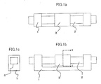
- the linear driving device comprises three members of a base 1, a stator 2 including an exciting coil and a slider 3 including permanent magnets.
- a linear motor is constituted by the stator 2 as a driving member and a slider 3 as a movable member driven by the stator 2.
- all of sliding faces of the base 1 and the stator 2 constitute air bearing surfaces of an air bearing so that the stator 2 is supported to move linearly only in axial opposite directions on the base 1 by the air bearing, in contrast to a conventional arrangement of a stator being fixedly mounted on the base.
- all of sliding faces of the slider 3 and the stator 2 constitute air bearing surfaces 4 of an air bearing so that the slider 3 is supported on the stator 2 to move linearly only in the same axial opposite directions as the linear of motion of the stator 2 by the air bearing.
- the stator 2 has a form of a rectangular rod as shown in FIG.
- stator 2 functions as a guide of the air bearing to restrict the motion of the slider 3 to axial opposite directions in order to simplify the structure of the liner driving device.
- stator 2 and the slider 3 are supported coaxially along an axis of linear motions thereof.
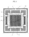
- the stator 2 comprises a core 21 arranged at a central portion thereof and an exciting coil 22 wound on the core 21.
- the coil 22 is coated with a resin layer 23 by molding.
- the resin layer 23 has flat outer surfaces abraded to form the air bearing surfaces of the air bearing.
- the slider 3 has a rectangular through hole and permanent magnets 31 with associated magnetic cores 32 on inner opposite sides. Surfaces of the magnets 31 constitute the air bearing surfaces 4.
- an air-supplying path 33 for supplying pressurized air between the air bearing surfaces 4 is formed inside the slider 3.
- the slider 3 is driven according to a principle of a known linear motor.
- the slider 3 is driven by an electromagnetic force generated by a magnetic field produced by electric current on the coil 22 and a magnetic field of the magnets 31.
- the stator is accelerated in the other opposite axial direction by the reactive force of the acceleration force.
- the stator is decelerated in the other opposite axial direction by the reactive force of the deceleration force.
- the frictional resistance in the axial direction is substantially zero since the stator 2 is supported on the base by the air bearing, and therefore no force is transmitted from the moving stator 2 to the base 1.
- the stator 2 has to have a length of a sum of the stroke of the slider 3 and the stroke of the stator 2, the length of the stator is made greater than that of the conventional linear driving device.
- a ratio of weights of the slider 3 and the stator 2 is set so that the weight of the stator 2 is greater than the weight of the slider 3, to shorten the stroke and thus length of the stator 2.
- FIGS. 4 shows transition of positions of the slider 3 and the stator 2 in time series while the slider 3 is driven to reciprocate.
- weight of the stator 2 is five-times greater than weight of the slider 3, i.e., a ratio of weight of the stator 2 to weight of the slider 3 is 5:1.
- the slider 3 is driven to move in the right-hand direction and reciprocates between a right-hand extreme position in the state (c) and a left-hand extreme position in the state (g).
- the slider 3 and the stator 2 move in the same axial opposite directions and have different strokes.
- a center of gravity of a combination of these elements is not changed.
- no change of the center of gravity affects the linear driving device. Since the reactive force exerted on the stator 2 is not transmitted to the base 1 of the linear driving device,and the center of gravity does not change with the motions of the slider 3 and the stator 2, a linear driving device with no reaction in high-speed motion is realized.
- the linear driving device Since the linear driving device is designed to be used for driving an object to be reciprocated at a high speed, the position of the slider 3 is not controlled but the speed of the slider 3 is controlled. As described, the relationship between the relative motions of the stator 2 and the slider 3 is not changed since they are determined by the ratio of weights of the two members.
- the positional relationship in motion of the stator 2 with respect to the base 1 may be displaced slightly because of an air resistance and elastic force from of power cables connected to the stator 2.
- the power cables 5 are arranged to be wired so that the stator 2 is returned to the central position on the base 1 utilizing elasticity of the cables functioning as weak springs.
- Additional weak springs may be used to be mounted on both ends of the stator 2 so that the stator 2 is urged to return to a predetermined position (central position). Further, in this embodiment, shapes of the stator 2 and the slider 3 are determined so that the weights of these members are distributed symmetrically with respect to a central axis thereof, as shown in FIG. 2, in order to prevent producing of a moment to rotate the elements in acceleration and deceleration. If an object connected to an upper side of the slider 3 causes an unbalance of the combination of the slider 3 and the stator 2, a counterbalance may be added to adjust the balance.
- a linear motor is constituted by the stator 2 and the slider 3.
- a voice-coil motor may be constituted in a similar manner.
- air bearings are used between the stator 2 and the base 1 and also between the stator 2 and the slider 3, although hydraulic bearings such as oil bearings may be used therebetween.
- the bearing provided between the stator 2 and the slider 3 may be a bearing other thanan hydraulic bearing in order to fulfill the object and effect of the present invention.
- the hydraulic bearing is provided at least between the stator and the base 1 not to transmit the forces produced in acceleration and deceleration of the slider 3 to the base 1.
- the reactive force produced in acceleration and deceleration of the slider which has been a problem in a high-speed and high-precision linear driving device, is fundamentally canceled within the device, so that high-speed and precise measurement or machining may be realized by employing the linear driving device of the present invention in a measuring device or a machining tool.
Landscapes
- Engineering & Computer Science (AREA)
- Power Engineering (AREA)
- Linear Motors (AREA)
- Machine Tool Units (AREA)
Abstract

Description
Claims (9)
- A linear driving device comprising:a base;a driving member supported movably with respect to said base in opposite linear directions on said base; anda slider driven by said driving member and supported movably with respect to said driving member in the same, opposite, linear directions as said driving member.
- A linear driving device according to claim 1, wherein said driving member is supported by means of an air bearing or an hydraulic bearing.
- A linear driving device according to claim 2, wherein an exciting coil of said driving member is coated with a resin layer so that a surface of the resin layer constitutes a bearing surface of the air or hydraulic bearing.
- A linear driving device according to any preceding claim, wherein said slider is supported by means of an air bearing or an hydraulic bearing.
- A linear driving device according to claim 4, wherein an exciting coil of said driving member is coated with a resin layer so that a surface of the resin layer constitutes a bearing surface of the air or hydraulic bearing.
- A linear driving device according to any preceding claim, wherein said driving member and said slider have different weights.
- A linear driving device according to any preceding claim, wherein weight distributions of said driving member and said slider are symmetrical with respect to an axis of motion thereof.
- A linear driving device according to any preceding claim, further comprising power cables for supplying an electric power to said driving member, said power cables being arranged between said base and said driving member to function as a spring for producing elastic force to said driving member in the direction of linear motion thereof.
- A linear driving device according to any preceding claim, wherein said driving member and said slider constitute a linear motor.
Applications Claiming Priority (2)
| Application Number | Priority Date | Filing Date | Title |
|---|---|---|---|
| JP2001087256A JP2002283174A (en) | 2001-03-26 | 2001-03-26 | Linear drive |
| JP2001087256 | 2001-03-26 |
Publications (3)
| Publication Number | Publication Date |
|---|---|
| EP1246350A2 true EP1246350A2 (en) | 2002-10-02 |
| EP1246350A3 EP1246350A3 (en) | 2005-08-10 |
| EP1246350B1 EP1246350B1 (en) | 2008-03-05 |
Family
ID=18942526
Family Applications (1)
| Application Number | Title | Priority Date | Filing Date |
|---|---|---|---|
| EP02251994A Expired - Lifetime EP1246350B1 (en) | 2001-03-26 | 2002-03-20 | Linear driving device |
Country Status (4)
| Country | Link |
|---|---|
| US (1) | US6765318B2 (en) |
| EP (1) | EP1246350B1 (en) |
| JP (1) | JP2002283174A (en) |
| DE (1) | DE60225369T2 (en) |
Families Citing this family (10)
| Publication number | Priority date | Publication date | Assignee | Title |
|---|---|---|---|---|
| ITMI20021505A1 (en) * | 2002-07-10 | 2004-01-12 | Danieli Off Mecc | ROLLER SUPPORT DEVICE FOR CONTINUOUS CASTING OF METAL TAPE |
| WO2004032313A1 (en) * | 2002-10-04 | 2004-04-15 | Tokyo Seimitsu Co., Ltd. | Surface shape measuring apparatus and single-shaft driver for use therein |
| JP3945716B2 (en) | 2005-12-14 | 2007-07-18 | インターナショナル・ビジネス・マシーンズ・コーポレーション | End mill and manufacturing method thereof |
| JP4382133B2 (en) * | 2008-03-11 | 2009-12-09 | ファナック株式会社 | Processing machine with shuttle |
| JP4586088B2 (en) * | 2008-08-19 | 2010-11-24 | ファナック株式会社 | Reciprocating linear drive device |
| US8174154B2 (en) * | 2008-10-22 | 2012-05-08 | Alio Industries, Inc. | Air bushing linear stage system |
| RU2512672C2 (en) | 2008-11-21 | 2014-04-10 | Хадар МАГАЛИ | Chipping mechanism |
| CN102205506B (en) * | 2010-03-29 | 2014-07-02 | 发那科株式会社 | Linear driving device with structure for clamping or switching cable |
| KR101258407B1 (en) | 2011-12-06 | 2013-04-26 | 주식회사 져스텍 | Reaction force compensation linear motion system |
| US9513168B2 (en) * | 2014-09-23 | 2016-12-06 | Utah State University Research Foundation | Linear-motion stage |
Family Cites Families (19)
| Publication number | Priority date | Publication date | Assignee | Title |
|---|---|---|---|---|
| JPS5963973A (en) | 1982-10-05 | 1984-04-11 | Toshiba Corp | Stepping motor |
| JPS60150950A (en) * | 1984-01-20 | 1985-08-08 | Hitachi Ltd | Guidance device |
| US4509006A (en) * | 1984-03-26 | 1985-04-02 | The Boeing Company | Multiple annulus energy storage system |
| JPS62108185A (en) * | 1985-11-06 | 1987-05-19 | 大日本スクリ−ン製造株式会社 | Movable table device |
| EP0393994B1 (en) * | 1989-04-17 | 1994-06-15 | SHARP Corporation | A linear driving apparatus |
| JPH0463333A (en) | 1990-05-14 | 1992-02-28 | Sharp Corp | Polarizing screen for liquid crystal projector |
| US5317221A (en) * | 1991-09-04 | 1994-05-31 | Canon Kabushiki Kaisha | Linear driving device |
| US5504407A (en) * | 1992-02-21 | 1996-04-02 | Canon Kabushiki Kaisha | Stage driving system |
| US6155721A (en) * | 1994-04-01 | 2000-12-05 | Sankyo Seiki Mfg. Co., Ltd. | Dynamic-pressure fluid bearing |
| US6330837B1 (en) * | 1997-08-28 | 2001-12-18 | Microdexterity Systems, Inc. | Parallel mechanism |
| JPH11164542A (en) * | 1997-09-17 | 1999-06-18 | Minolta Co Ltd | Linear motor and image reading device |
| JP3358108B2 (en) * | 1997-09-19 | 2002-12-16 | 株式会社ニコン | Exposure apparatus, scanning exposure apparatus, and scanning exposure method |
| JP3186674B2 (en) | 1997-11-13 | 2001-07-11 | 株式会社豊田自動織機製作所 | Contactless power supply system |
| DE19810996A1 (en) | 1998-03-13 | 1999-09-16 | Krauss Maffei Ag | Motor to drive useful load in machine |
| JP3182125B2 (en) * | 1998-06-09 | 2001-07-03 | ファナック株式会社 | Air bearing motor |
| JP2000002233A (en) * | 1998-06-12 | 2000-01-07 | Sumitomo Electric Ind Ltd | Dynamic pressure gas bearing and manufacturing method thereof |
| US6193199B1 (en) * | 1998-07-15 | 2001-02-27 | Nanomotion, Inc. | Sample stage including a slider assembly |
| US6285097B1 (en) * | 1999-05-11 | 2001-09-04 | Nikon Corporation | Planar electric motor and positioning device having transverse magnets |
| TW546551B (en) * | 1999-12-21 | 2003-08-11 | Asml Netherlands Bv | Balanced positioning system for use in lithographic apparatus |
-
2001
- 2001-03-26 JP JP2001087256A patent/JP2002283174A/en active Pending
-
2002
- 2002-03-18 US US10/098,462 patent/US6765318B2/en not_active Expired - Lifetime
- 2002-03-20 EP EP02251994A patent/EP1246350B1/en not_active Expired - Lifetime
- 2002-03-20 DE DE60225369T patent/DE60225369T2/en not_active Expired - Lifetime
Also Published As
| Publication number | Publication date |
|---|---|
| DE60225369D1 (en) | 2008-04-17 |
| EP1246350A3 (en) | 2005-08-10 |
| DE60225369T2 (en) | 2009-03-26 |
| US6765318B2 (en) | 2004-07-20 |
| US20020135240A1 (en) | 2002-09-26 |
| JP2002283174A (en) | 2002-10-03 |
| EP1246350B1 (en) | 2008-03-05 |
Similar Documents
| Publication | Publication Date | Title |
|---|---|---|
| US20180104779A1 (en) | Single-drive rigid-flexible coupling precision motion platform and realization method and application thereof | |
| US5180955A (en) | Positioning apparatus | |
| CN105634241B (en) | Micro-nano positioning device and its voice coil motor | |
| EP1246350B1 (en) | Linear driving device | |
| JP2001352747A (en) | Linear motor and press molding machine using the same as drive source | |
| KR100851058B1 (en) | Planar Stage Shifters for Machinery | |
| EP2100695B1 (en) | Processing machine with reciprocation device | |
| US5962937A (en) | X-Y table for moving loads in a highly exact and dynamic manner | |
| EP0967022A1 (en) | Vibration generating mechanism | |
| Tomita et al. | High-response XY stage system driven by in-parallel linear motors | |
| KR101258407B1 (en) | Reaction force compensation linear motion system | |
| JP2024514729A (en) | Linear Motor Module | |
| CN205544874U (en) | Receive positioner a little and voice coil motor thereof | |
| CN105281536A (en) | Drive for an XY-Table and XY-Table | |
| JP6355938B2 (en) | Stage device with bracket | |
| US6166465A (en) | Vibration generating mechanism using repulsive forces of permanent magnets | |
| CN223666152U (en) | Voice coil motor and distance adjusting device | |
| KR101910639B1 (en) | Spring Electromagnet Structure | |
| US7518268B2 (en) | Linear stage including an integrated actuator and associated methods | |
| CN109465651A (en) | Friction-type stiffness switching device and rigid-flexible coupling motion platform and method using the same | |
| CN218243308U (en) | Pushing device | |
| KR102391658B1 (en) | Actuator with gravity compensation | |
| JP3910564B2 (en) | Linear motor drive linear motion device | |
| JP4002339B2 (en) | Excitation mechanism | |
| JP2001225285A (en) | Mobile system |
Legal Events
| Date | Code | Title | Description |
|---|---|---|---|
| PUAI | Public reference made under article 153(3) epc to a published international application that has entered the european phase |
Free format text: ORIGINAL CODE: 0009012 |
|
| AK | Designated contracting states |
Kind code of ref document: A2 Designated state(s): AT BE CH CY DE DK ES FI FR GB GR IE IT LI LU MC NL PT SE TR |
|
| AX | Request for extension of the european patent |
Free format text: AL;LT;LV;MK;RO;SI |
|
| RAP1 | Party data changed (applicant data changed or rights of an application transferred) |
Owner name: FANUC LTD |
|
| PUAL | Search report despatched |
Free format text: ORIGINAL CODE: 0009013 |
|
| AK | Designated contracting states |
Kind code of ref document: A3 Designated state(s): AT BE CH CY DE DK ES FI FR GB GR IE IT LI LU MC NL PT SE TR |
|
| AX | Request for extension of the european patent |
Extension state: AL LT LV MK RO SI |
|
| 17P | Request for examination filed |
Effective date: 20060206 |
|
| AKX | Designation fees paid |
Designated state(s): DE |
|
| 17Q | First examination report despatched |
Effective date: 20070403 |
|
| GRAP | Despatch of communication of intention to grant a patent |
Free format text: ORIGINAL CODE: EPIDOSNIGR1 |
|
| GRAS | Grant fee paid |
Free format text: ORIGINAL CODE: EPIDOSNIGR3 |
|
| GRAA | (expected) grant |
Free format text: ORIGINAL CODE: 0009210 |
|
| AK | Designated contracting states |
Kind code of ref document: B1 Designated state(s): DE |
|
| REF | Corresponds to: |
Ref document number: 60225369 Country of ref document: DE Date of ref document: 20080417 Kind code of ref document: P |
|
| PLBE | No opposition filed within time limit |
Free format text: ORIGINAL CODE: 0009261 |
|
| STAA | Information on the status of an ep patent application or granted ep patent |
Free format text: STATUS: NO OPPOSITION FILED WITHIN TIME LIMIT |
|
| 26N | No opposition filed |
Effective date: 20081208 |
|
| REG | Reference to a national code |
Ref country code: DE Ref legal event code: R082 Ref document number: 60225369 Country of ref document: DE Representative=s name: HL KEMPNER PATENTANWALT, RECHTSANWALT, SOLICIT, DE |
|
| PGFP | Annual fee paid to national office [announced via postgrant information from national office to epo] |
Ref country code: DE Payment date: 20210310 Year of fee payment: 20 |
|
| REG | Reference to a national code |
Ref country code: DE Ref legal event code: R071 Ref document number: 60225369 Country of ref document: DE |