EP1246311A1 - Cable clamp - Google Patents
Cable clamp Download PDFInfo
- Publication number
- EP1246311A1 EP1246311A1 EP02076236A EP02076236A EP1246311A1 EP 1246311 A1 EP1246311 A1 EP 1246311A1 EP 02076236 A EP02076236 A EP 02076236A EP 02076236 A EP02076236 A EP 02076236A EP 1246311 A1 EP1246311 A1 EP 1246311A1
- Authority
- EP
- European Patent Office
- Prior art keywords
- clamping part
- clamping
- passage
- housing
- fastening
- Prior art date
- Legal status (The legal status is an assumption and is not a legal conclusion. Google has not performed a legal analysis and makes no representation as to the accuracy of the status listed.)
- Granted
Links
- 238000006073 displacement reaction Methods 0.000 description 1
- 238000000034 method Methods 0.000 description 1
Images


Classifications
-
- H—ELECTRICITY
- H01—ELECTRIC ELEMENTS
- H01R—ELECTRICALLY-CONDUCTIVE CONNECTIONS; STRUCTURAL ASSOCIATIONS OF A PLURALITY OF MUTUALLY-INSULATED ELECTRICAL CONNECTING ELEMENTS; COUPLING DEVICES; CURRENT COLLECTORS
- H01R13/00—Details of coupling devices of the kinds covered by groups H01R12/70 or H01R24/00 - H01R33/00
- H01R13/58—Means for relieving strain on wire connection, e.g. cord grip, for avoiding loosening of connections between wires and terminals within a coupling device terminating a cable
- H01R13/59—Threaded ferrule or bolt operating in a direction parallel to the cable or wire
Definitions
- the invention relates to a device for clamping a cable, comprising a clamping part having at least one passage for receiving a cable and at least one resilient finger movable to reduce the size of the passage, a housing part having a passage with a chamber at one end for receiving the clamping part, and a fastening part to fasten the clamping part and housing part to one another to thereby force the resilient finger(s) inwardly to reduce the size of the passage of the clamping part.
- EP-A-0 913 900 discloses a device for clamping a cable of this type, wherein the housing part consists of two housing halves together determining a mainly cylindrical passage for receiving the clamping part.
- the resilient fingers of the clamping part are provided with radial projections pressing the resilient fingers inwardly to reduce the size of the passage of the clamping part so that the fingers grip the outer side of the jacket of the cable.
- the two housing halves are fixed together by means of clamping bolds.
- EP-A-0 736 933 discloses a cable connector, wherein a housing of the connector is provided with a conical clamping device for connecting the shielding of the cable to the housing of the connector.
- the cable is clamped to the housing of the connector by means of a clamping strip.
- the invention aims to provide an improved device of the above-mentioned type.
- the device for clamping a cable of the invention is characterized in that the clamping part comprises a conical section with a conical outer side, the conical section including the resilient finger(s) and in that the chamber of the housing part is provided with a conical inner wall adapted to engage the conical outer side of at least the resilient finger(s), wherein the fastening part forces the clamping part axially into the chamber during fastening to thereby force the resilient finger(s) inwardly.
- a device for clamping a cable wherein the conical section of the clamping part and the conical inner wall of the chamber of the housing part are cooperating to force the resilient fingers inwardly to thereby grip the outer side of the cable.
- the clamping part moves axially into the chamber, wherein the axial movement of the clamping part is translated into a radial movement of the resilient fingers.
- the performance of the clamping operation of the device is largely independent of variation in cable diameter, so that tolerances of cable diameter are not critical. In applications of the device of the invention in a cable connector, wherein the clamping part is located at the inner side of the cable connector, the clamping operation of the device will increase if a pulling force is exerted on the cable.
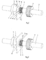
- Fig. 1 is a perspective view of an embodiment of the device of the invention during assembly.
- Fig. 2 is a perspective view of the device of fig. 1 during assembly.
- Fig. 3 is a perspective view of the device of fig. 1 as fully assembled.
- Fig. 4 shows a perspective view of the device of fig. 1 partly disassembled.
- Fig. 5 is a perspective view of a further embodiment of the device of the invention as fully assembled.
- Fig. 6 is a perspective view of a further embodiment of the device of the invention during assembly.
- Fig. 7 shows a perspective view of the device of fig. 6.
- Figs. 1-4 show an embodiment of a cable clamp or device for clamping a cable, wherein the device is shown in a fully assembled state in fig. 3.
- the device comprises a clamping part 1 having a passage 2 for receiving a cable 3 and three resilient fingers 4, wherein the fingers 4 are moveable inwardly to reduce the size of the passage 2. It will be understood that a different number of resilient fingers can be used.
- the device further comprises a housing part 5 having a passage 6 with a chamber 7 at one end for receiving the clamping part 1.
- the housing part comprises two housings halves 8.
- the housing part 5, i.e. the housing halves 8 are part of a cable connector housing not further shown. The invention is however not restricted to use of the device described in cable connectors.
- a fastening part 9 which in the embodiment shown is made as a nut, is provided to fasten the clamping part 1 and housing part 5 to one another to obtain the fully assembled state of fig. 3.
- the clamping part 1 comprises a conical section 10 with a conical outer side and this conical section includes the resilient fingers 4.
- the chamber 7 of the housing part 5 is provided with a conical inner wall adapted to engage the conical outer side of the fingers 4.
- the clamping part 1 is provided with a fastening section 11 having a screw thread. This fastening section projects out of the passage 6 of the housing part 5 when the conical section 11 is received in the conical chamber 7 as shown in figs. 1 and 2.
- the clamping part 1 When the nut 9 is fastened on the fastening section 11, the clamping part 1 will be pulled in axial direction into the conical chamber 7 so that the resilient fingers 4 are forced inwardly to reduce the size of the passage 2 and the cable 3 will be clamped within the passage 2.
- the clamping part 1 is provided with a section 12 having a plurality of flat outer services 13.
- the passage 6 of the housing part 5 is provided with a section 14 having a plurality of flat inner walls 15 engaging the flat outer services 13 of the clamping part 1.
- the housing halves 8 each are provided with a projecting collar 16 enclosing a part of the passage 6 of the housing.
- the collar 16 is received in an annular space of the nut 9. It will be understood that if the housing part 5 is a single part, it is not necessary to provide the housing part with a collar.
- Fig. 5 shows an embodiment of the device described, wherein the housing part 5 is provided with a resilient locking element 17 having a projection 18 at its free end engaging in a groove of the serrated outer side 19 of the nut 9. In this manner the nut 9 will be automatically locked so that it can not be unscrewed unintentionally.
- Figs. 6 and 7 show a further embodiment of the invention, wherein a clamping part 20 is used having two passages 21 for cables 3. For each passage 21 three resilient fingers 22 are provided, wherein the fingers 22 together determine the conical section 10 of the clamping part 20.
- one housing half 8 is shown and the nut 9 is not yet screwed on the fastening section 11 of the clamping part 20.
- the fastening section 11 in this case includes the section 12 with flat surfaces 13.
- the housing half 8 determines half of the passage 6 of the housing part with a chamber 7 with conical inner wall.
- the device for clamping a cable described shows the advantage that the clamping performance is independent of variations in diameter of the cables 3, so that tolerances of cable diameters are not critical. An efficient squeezing of the cable(s) is obtained, so that after assembly of the device displacement of the cable can not occur and no stress can be exerted on terminated wires of the cable. Moreover, if a pulling force is exerted on the cable, the clamping part 1, 19 will be tensioned such that the clamping part 1, 9 will be locked even more tightly. No special tools are required to assemble the clamping device. If the device is used in a cable connector for example, the wires of the cable can be terminated and the clamping device can be assembled at the end of the termination procedure. Moreover the clamping device can be dismantled easily and is fully repairable. In case of a one piece housing part 5, the clamping part 1, 19 and fastening part 9 can be pre-assembled.
Landscapes
- Installation Of Indoor Wiring (AREA)
- Details Of Connecting Devices For Male And Female Coupling (AREA)
- Insulated Conductors (AREA)
- Cable Accessories (AREA)
Abstract
Description
- The invention relates to a device for clamping a cable, comprising a clamping part having at least one passage for receiving a cable and at least one resilient finger movable to reduce the size of the passage, a housing part having a passage with a chamber at one end for receiving the clamping part, and a fastening part to fasten the clamping part and housing part to one another to thereby force the resilient finger(s) inwardly to reduce the size of the passage of the clamping part.
- EP-A-0 913 900 discloses a device for clamping a cable of this type, wherein the housing part consists of two housing halves together determining a mainly cylindrical passage for receiving the clamping part. The resilient fingers of the clamping part are provided with radial projections pressing the resilient fingers inwardly to reduce the size of the passage of the clamping part so that the fingers grip the outer side of the jacket of the cable. The two housing halves are fixed together by means of clamping bolds.
- EP-A-0 736 933 discloses a cable connector, wherein a housing of the connector is provided with a conical clamping device for connecting the shielding of the cable to the housing of the connector. The cable is clamped to the housing of the connector by means of a clamping strip.
- The invention aims to provide an improved device of the above-mentioned type.
- To this end the device for clamping a cable of the invention is characterized in that the clamping part comprises a conical section with a conical outer side, the conical section including the resilient finger(s) and in that the chamber of the housing part is provided with a conical inner wall adapted to engage the conical outer side of at least the resilient finger(s), wherein the fastening part forces the clamping part axially into the chamber during fastening to thereby force the resilient finger(s) inwardly.
- In this manner a device for clamping a cable is obtained wherein the conical section of the clamping part and the conical inner wall of the chamber of the housing part are cooperating to force the resilient fingers inwardly to thereby grip the outer side of the cable. The clamping part moves axially into the chamber, wherein the axial movement of the clamping part is translated into a radial movement of the resilient fingers. The performance of the clamping operation of the device is largely independent of variation in cable diameter, so that tolerances of cable diameter are not critical. In applications of the device of the invention in a cable connector, wherein the clamping part is located at the inner side of the cable connector, the clamping operation of the device will increase if a pulling force is exerted on the cable.
- The invention will be further explained by reference to the drawings in which some embodiments of the device of the invention are shown.
- Fig. 1 is a perspective view of an embodiment of the device of the invention during assembly.
- Fig. 2 is a perspective view of the device of fig. 1 during assembly.
- Fig. 3 is a perspective view of the device of fig. 1 as fully assembled.
- Fig. 4 shows a perspective view of the device of fig. 1 partly disassembled.
- Fig. 5 is a perspective view of a further embodiment of the device of the invention as fully assembled.
- Fig. 6 is a perspective view of a further embodiment of the device of the invention during assembly.
- Fig. 7 shows a perspective view of the device of fig. 6.
- Figs. 1-4 show an embodiment of a cable clamp or device for clamping a cable, wherein the device is shown in a fully assembled state in fig. 3. The device comprises a
clamping part 1 having apassage 2 for receiving acable 3 and threeresilient fingers 4, wherein thefingers 4 are moveable inwardly to reduce the size of thepassage 2. It will be understood that a different number of resilient fingers can be used. - The device further comprises a
housing part 5 having apassage 6 with achamber 7 at one end for receiving theclamping part 1. As shown in the drawings, the housing part comprises twohousings halves 8. In a preferred embodiment of the invention, thehousing part 5, i.e. thehousing halves 8, are part of a cable connector housing not further shown. The invention is however not restricted to use of the device described in cable connectors. - A fastening
part 9 which in the embodiment shown is made as a nut, is provided to fasten theclamping part 1 andhousing part 5 to one another to obtain the fully assembled state of fig. 3. - As clearly shown in the drawings, the
clamping part 1 comprises aconical section 10 with a conical outer side and this conical section includes theresilient fingers 4. Thechamber 7 of thehousing part 5 is provided with a conical inner wall adapted to engage the conical outer side of thefingers 4. At its axial end opposite of theconical section 10 theclamping part 1 is provided with afastening section 11 having a screw thread. This fastening section projects out of thepassage 6 of thehousing part 5 when theconical section 11 is received in theconical chamber 7 as shown in figs. 1 and 2. When thenut 9 is fastened on thefastening section 11, theclamping part 1 will be pulled in axial direction into theconical chamber 7 so that theresilient fingers 4 are forced inwardly to reduce the size of thepassage 2 and thecable 3 will be clamped within thepassage 2. - Rotation of the
clamping part 1 is prevented as the clamping part is provided with asection 12 having a plurality of flatouter services 13. Thepassage 6 of thehousing part 5 is provided with asection 14 having a plurality of flatinner walls 15 engaging the flatouter services 13 of theclamping part 1. - To prevent opening of the
housing halves 8 by the mutual co-operation of theconical clamping part 1 and theconical chamber 6, thehousing halves 8 each are provided with a projectingcollar 16 enclosing a part of thepassage 6 of the housing. Thecollar 16 is received in an annular space of thenut 9. It will be understood that if thehousing part 5 is a single part, it is not necessary to provide the housing part with a collar. - Fig. 5 shows an embodiment of the device described, wherein the
housing part 5 is provided with aresilient locking element 17 having aprojection 18 at its free end engaging in a groove of the serratedouter side 19 of thenut 9. In this manner thenut 9 will be automatically locked so that it can not be unscrewed unintentionally. - Figs. 6 and 7 show a further embodiment of the invention, wherein a
clamping part 20 is used having twopassages 21 forcables 3. For eachpassage 21 threeresilient fingers 22 are provided, wherein thefingers 22 together determine theconical section 10 of theclamping part 20. In fig. 6 onehousing half 8 is shown and thenut 9 is not yet screwed on thefastening section 11 of theclamping part 20. It can be clearly seen that thefastening section 11 in this case includes thesection 12 withflat surfaces 13. Further it can be seen that thehousing half 8 determines half of thepassage 6 of the housing part with achamber 7 with conical inner wall. - In fig. 7, the
nut 9 has been fastened on thefastening section 11 of theclamping part 20 so that theresilient fingers 22 are forced inwardly by the co-operation between the conical parts of clampingpart 20 andhousing part 5. - The device for clamping a cable described shows the advantage that the clamping performance is independent of variations in diameter of the
cables 3, so that tolerances of cable diameters are not critical. An efficient squeezing of the cable(s) is obtained, so that after assembly of the device displacement of the cable can not occur and no stress can be exerted on terminated wires of the cable. Moreover, if a pulling force is exerted on the cable, theclamping part clamping part part 5, theclamping part part 9 can be pre-assembled. - The invention is not restricted to the above described embodiments which can be varied in a number of ways within the scope of the attached claims.
Claims (7)
- Device for clamping a cable, comprising a clamping part (1,20) having at least one passage (2,21) for receiving a cable (3) and at least one resilient finger (4,22) movable to reduce the size of the passage, a housing part (5) having a passage (6) with a chamber (7) at one end for receiving the clamping part (1,20), and a fastening part (9) to fasten the clamping part and housing part to one another to thereby force the resilient finger(s) (4,22) inwardly to reduce the size of the passage of the clamping part, characterized in that the clamping part (1,20) comprises a conical section (10) with a conical outer side, the conical section (10) including the resilient finger(s) (4,22) and in that the chamber (7) of the housing part (5) is provided with a conical inner wall adapted to engage the conical outer side of at least the resilient finger(s) (4,22), wherein the fastening part (9) forces the clamping part (1,20) axially into the chamber (7) during fastening to thereby force the resilient finger(s) (4,22) inwardly.
- Device according to claim 1, wherein the clamping part (1,20) is provided with a section (12) having one or more flat outer surfaces (13), wherein the passage (6) of the housing part (5) is provided with a section (14) having one or more flat inner walls (15) adapted to engage the flat outer surfaces of the clamping part.
- Device according to claim 1 or 2, wherein the clamping part (1,20) is provided with a fastening section (11) opposite of the conical section (7), said fastening section (11) projecting out of the passage (6) of the housing part (5) when the conical section (10) is received in the conical chamber (7), wherein the fastening section (11) is adapted to cooperate with the fastening part (9) to fasten the clamping part (1,20) in the chamber (7) of the housing part (5).
- Device according to any one of the preceding claims, wherein the housing part (5) comprises two housing halves (8), wherein the housing halves each are provided with a projecting collar (16) enclosing a part of the passage (6) of the housing part (5) opposite of the chamber (7), wherein the fastening part (9) is provided with annular space for receiving the collar (16).
- Device according to any one of the preceding claims, wherein the fastening part (9) is made as a nut, wherein the housing part (5) is provided with a locking element (17) for locking the nut.
- Device according to any one of the preceding claims, wherein the clamping part (20) is provided with two passages (21), wherein at least one resilient finger (22) is located at the circumference of each passage, and wherein the resilient fingers of all passages are part of the conical section (10) of the clamping part (20) and are forced inwardly to reduce the size of the corresponding passage during fastening of the clamping and housing parts.
- Clamping part (1,20) for a device according to any one of the preceding claims.
Applications Claiming Priority (2)
| Application Number | Priority Date | Filing Date | Title |
|---|---|---|---|
| NL1017734 | 2001-03-29 | ||
| NL1017734A NL1017734C2 (en) | 2001-03-29 | 2001-03-29 | Cable clamp. |
Publications (2)
| Publication Number | Publication Date |
|---|---|
| EP1246311A1 true EP1246311A1 (en) | 2002-10-02 |
| EP1246311B1 EP1246311B1 (en) | 2004-06-09 |
Family
ID=19773157
Family Applications (1)
| Application Number | Title | Priority Date | Filing Date |
|---|---|---|---|
| EP02076236A Expired - Lifetime EP1246311B1 (en) | 2001-03-29 | 2002-03-26 | Cable clamp |
Country Status (4)
| Country | Link |
|---|---|
| EP (1) | EP1246311B1 (en) |
| AT (1) | ATE268953T1 (en) |
| DE (1) | DE60200598T2 (en) |
| NL (1) | NL1017734C2 (en) |
Cited By (1)
| Publication number | Priority date | Publication date | Assignee | Title |
|---|---|---|---|---|
| CN113960432A (en) * | 2021-10-29 | 2022-01-21 | 国网河南省电力公司南阳供电公司 | Cable joint partial discharge current detection device |
Citations (5)
| Publication number | Priority date | Publication date | Assignee | Title |
|---|---|---|---|---|
| US2250685A (en) * | 1939-11-24 | 1941-07-29 | Thomas B Tiefenbacher | Locking device |
| GB950197A (en) * | 1959-06-29 | 1964-02-19 | Andre Marcel Charpigny | Improvements in or relating to electric cable glands |
| US3649054A (en) * | 1970-12-03 | 1972-03-14 | Warren G Mcclenan | Cable fitting for ship bulkheads |
| US3801131A (en) * | 1973-04-30 | 1974-04-02 | Appleton Electric Co | Sealed electrical connector for securing conduits to junction boxes |
| US4065201A (en) * | 1976-11-19 | 1977-12-27 | E. F. Johnson Company | Connector |
-
2001
- 2001-03-29 NL NL1017734A patent/NL1017734C2/en not_active IP Right Cessation
-
2002
- 2002-03-26 AT AT02076236T patent/ATE268953T1/en not_active IP Right Cessation
- 2002-03-26 DE DE60200598T patent/DE60200598T2/en not_active Expired - Fee Related
- 2002-03-26 EP EP02076236A patent/EP1246311B1/en not_active Expired - Lifetime
Patent Citations (5)
| Publication number | Priority date | Publication date | Assignee | Title |
|---|---|---|---|---|
| US2250685A (en) * | 1939-11-24 | 1941-07-29 | Thomas B Tiefenbacher | Locking device |
| GB950197A (en) * | 1959-06-29 | 1964-02-19 | Andre Marcel Charpigny | Improvements in or relating to electric cable glands |
| US3649054A (en) * | 1970-12-03 | 1972-03-14 | Warren G Mcclenan | Cable fitting for ship bulkheads |
| US3801131A (en) * | 1973-04-30 | 1974-04-02 | Appleton Electric Co | Sealed electrical connector for securing conduits to junction boxes |
| US4065201A (en) * | 1976-11-19 | 1977-12-27 | E. F. Johnson Company | Connector |
Cited By (1)
| Publication number | Priority date | Publication date | Assignee | Title |
|---|---|---|---|---|
| CN113960432A (en) * | 2021-10-29 | 2022-01-21 | 国网河南省电力公司南阳供电公司 | Cable joint partial discharge current detection device |
Also Published As
| Publication number | Publication date |
|---|---|
| ATE268953T1 (en) | 2004-06-15 |
| DE60200598T2 (en) | 2005-06-09 |
| DE60200598D1 (en) | 2004-07-15 |
| NL1017734C2 (en) | 2002-10-01 |
| EP1246311B1 (en) | 2004-06-09 |
Similar Documents
| Publication | Publication Date | Title |
|---|---|---|
| US6043432A (en) | Snap in cable connector | |
| CA2038448C (en) | Electrical connector for liquidtight conduit | |
| US6153830A (en) | Connector and method of operation | |
| US10446949B2 (en) | Coaxial cable connector sleeve | |
| US6335488B1 (en) | Snap in cable connector | |
| US5217393A (en) | Multi-fit coaxial cable connector | |
| US5755589A (en) | Multipin cable connector | |
| US7077699B2 (en) | Axial compression electrical connector | |
| US5632651A (en) | Radial compression type coaxial cable end connector | |
| US7357671B2 (en) | Coaxial plug-type connector and method for mounting the same | |
| US5276280A (en) | Electrical cable connector | |
| EP1468477B1 (en) | Flexible interconnect cable strain relief facility | |
| US7568934B1 (en) | Electrical connector having a sealing mechanism | |
| JP2012508431A (en) | Insertion coupling coaxial connector | |
| US9425540B2 (en) | Housing for a contact device | |
| JP2009297511A (en) | Female connector for self-locking connector system | |
| CN101939877A (en) | cable clamp | |
| US6220902B1 (en) | Method and apparatus for connecting an object to a device | |
| EP0986135B1 (en) | Shielded cable connector and method for connecting a shielded cable to it | |
| CN117355996A (en) | Clamping element for a cable connector unit and a cable connector unit comprising such a clamping element | |
| EP1246311B1 (en) | Cable clamp | |
| JP4066529B2 (en) | Flexible tube end holder | |
| US20240305040A1 (en) | Pinch Sleeve Assembly With Locking Feature | |
| JP2569866Y2 (en) | Flexible conduit fittings | |
| JPH0577883U (en) | Fitting connector |
Legal Events
| Date | Code | Title | Description |
|---|---|---|---|
| PUAI | Public reference made under article 153(3) epc to a published international application that has entered the european phase |
Free format text: ORIGINAL CODE: 0009012 |
|
| AK | Designated contracting states |
Kind code of ref document: A1 Designated state(s): AT BE CH CY DE DK ES FI FR GB GR IE IT LI LU MC NL PT SE TR |
|
| AX | Request for extension of the european patent |
Free format text: AL;LT;LV;MK;RO;SI |
|
| 17P | Request for examination filed |
Effective date: 20030331 |
|
| AKX | Designation fees paid |
Designated state(s): AT BE CH CY DE DK ES FI FR GB GR IE IT LI LU MC NL PT SE TR |
|
| 17Q | First examination report despatched |
Effective date: 20030526 |
|
| GRAP | Despatch of communication of intention to grant a patent |
Free format text: ORIGINAL CODE: EPIDOSNIGR1 |
|
| GRAS | Grant fee paid |
Free format text: ORIGINAL CODE: EPIDOSNIGR3 |
|
| GRAA | (expected) grant |
Free format text: ORIGINAL CODE: 0009210 |
|
| AK | Designated contracting states |
Kind code of ref document: B1 Designated state(s): AT BE CH CY DE DK ES FI FR GB GR IE IT LI LU MC NL PT SE TR |
|
| PG25 | Lapsed in a contracting state [announced via postgrant information from national office to epo] |
Ref country code: TR Free format text: LAPSE BECAUSE OF FAILURE TO SUBMIT A TRANSLATION OF THE DESCRIPTION OR TO PAY THE FEE WITHIN THE PRESCRIBED TIME-LIMIT Effective date: 20040609 Ref country code: NL Free format text: LAPSE BECAUSE OF FAILURE TO SUBMIT A TRANSLATION OF THE DESCRIPTION OR TO PAY THE FEE WITHIN THE PRESCRIBED TIME-LIMIT Effective date: 20040609 Ref country code: LI Free format text: LAPSE BECAUSE OF FAILURE TO SUBMIT A TRANSLATION OF THE DESCRIPTION OR TO PAY THE FEE WITHIN THE PRESCRIBED TIME-LIMIT Effective date: 20040609 Ref country code: IT Free format text: LAPSE BECAUSE OF FAILURE TO SUBMIT A TRANSLATION OF THE DESCRIPTION OR TO PAY THE FEE WITHIN THE PRESCRIBED TIME-LIMIT;WARNING: LAPSES OF ITALIAN PATENTS WITH EFFECTIVE DATE BEFORE 2007 MAY HAVE OCCURRED AT ANY TIME BEFORE 2007. THE CORRECT EFFECTIVE DATE MAY BE DIFFERENT FROM THE ONE RECORDED. Effective date: 20040609 Ref country code: FI Free format text: LAPSE BECAUSE OF FAILURE TO SUBMIT A TRANSLATION OF THE DESCRIPTION OR TO PAY THE FEE WITHIN THE PRESCRIBED TIME-LIMIT Effective date: 20040609 Ref country code: ES Free format text: LAPSE BECAUSE OF FAILURE TO SUBMIT A TRANSLATION OF THE DESCRIPTION OR TO PAY THE FEE WITHIN THE PRESCRIBED TIME-LIMIT Effective date: 20040609 Ref country code: CH Free format text: LAPSE BECAUSE OF FAILURE TO SUBMIT A TRANSLATION OF THE DESCRIPTION OR TO PAY THE FEE WITHIN THE PRESCRIBED TIME-LIMIT Effective date: 20040609 Ref country code: BE Free format text: LAPSE BECAUSE OF FAILURE TO SUBMIT A TRANSLATION OF THE DESCRIPTION OR TO PAY THE FEE WITHIN THE PRESCRIBED TIME-LIMIT Effective date: 20040609 Ref country code: AT Free format text: LAPSE BECAUSE OF FAILURE TO SUBMIT A TRANSLATION OF THE DESCRIPTION OR TO PAY THE FEE WITHIN THE PRESCRIBED TIME-LIMIT Effective date: 20040609 |
|
| REG | Reference to a national code |
Ref country code: GB Ref legal event code: FG4D |
|
| REG | Reference to a national code |
Ref country code: CH Ref legal event code: EP |
|
| REF | Corresponds to: |
Ref document number: 60200598 Country of ref document: DE Date of ref document: 20040715 Kind code of ref document: P |
|
| REG | Reference to a national code |
Ref country code: IE Ref legal event code: FG4D |
|
| PG25 | Lapsed in a contracting state [announced via postgrant information from national office to epo] |
Ref country code: SE Free format text: LAPSE BECAUSE OF FAILURE TO SUBMIT A TRANSLATION OF THE DESCRIPTION OR TO PAY THE FEE WITHIN THE PRESCRIBED TIME-LIMIT Effective date: 20040909 Ref country code: GR Free format text: LAPSE BECAUSE OF FAILURE TO SUBMIT A TRANSLATION OF THE DESCRIPTION OR TO PAY THE FEE WITHIN THE PRESCRIBED TIME-LIMIT Effective date: 20040909 Ref country code: DK Free format text: LAPSE BECAUSE OF FAILURE TO SUBMIT A TRANSLATION OF THE DESCRIPTION OR TO PAY THE FEE WITHIN THE PRESCRIBED TIME-LIMIT Effective date: 20040909 |
|
| NLV1 | Nl: lapsed or annulled due to failure to fulfill the requirements of art. 29p and 29m of the patents act | ||
| REG | Reference to a national code |
Ref country code: CH Ref legal event code: PL |
|
| PGFP | Annual fee paid to national office [announced via postgrant information from national office to epo] |
Ref country code: FR Payment date: 20050221 Year of fee payment: 4 |
|
| ET | Fr: translation filed | ||
| PG25 | Lapsed in a contracting state [announced via postgrant information from national office to epo] |
Ref country code: LU Free format text: LAPSE BECAUSE OF NON-PAYMENT OF DUE FEES Effective date: 20050326 Ref country code: CY Free format text: LAPSE BECAUSE OF FAILURE TO SUBMIT A TRANSLATION OF THE DESCRIPTION OR TO PAY THE FEE WITHIN THE PRESCRIBED TIME-LIMIT Effective date: 20050326 |
|
| PG25 | Lapsed in a contracting state [announced via postgrant information from national office to epo] |
Ref country code: IE Free format text: LAPSE BECAUSE OF NON-PAYMENT OF DUE FEES Effective date: 20050328 |
|
| PG25 | Lapsed in a contracting state [announced via postgrant information from national office to epo] |
Ref country code: MC Free format text: LAPSE BECAUSE OF NON-PAYMENT OF DUE FEES Effective date: 20050331 |
|
| PLBE | No opposition filed within time limit |
Free format text: ORIGINAL CODE: 0009261 |
|
| STAA | Information on the status of an ep patent application or granted ep patent |
Free format text: STATUS: NO OPPOSITION FILED WITHIN TIME LIMIT |
|
| PGFP | Annual fee paid to national office [announced via postgrant information from national office to epo] |
Ref country code: DE Payment date: 20050527 Year of fee payment: 4 |
|
| 26N | No opposition filed |
Effective date: 20050310 |
|
| REG | Reference to a national code |
Ref country code: IE Ref legal event code: MM4A |
|
| PG25 | Lapsed in a contracting state [announced via postgrant information from national office to epo] |
Ref country code: GB Free format text: LAPSE BECAUSE OF NON-PAYMENT OF DUE FEES Effective date: 20060326 |
|
| PG25 | Lapsed in a contracting state [announced via postgrant information from national office to epo] |
Ref country code: DE Free format text: LAPSE BECAUSE OF NON-PAYMENT OF DUE FEES Effective date: 20061003 |
|
| GBPC | Gb: european patent ceased through non-payment of renewal fee |
Effective date: 20060326 |
|
| REG | Reference to a national code |
Ref country code: FR Ref legal event code: ST Effective date: 20061130 |
|
| PG25 | Lapsed in a contracting state [announced via postgrant information from national office to epo] |
Ref country code: PT Free format text: LAPSE BECAUSE OF NON-PAYMENT OF DUE FEES Effective date: 20041109 |
|
| PG25 | Lapsed in a contracting state [announced via postgrant information from national office to epo] |
Ref country code: FR Free format text: LAPSE BECAUSE OF NON-PAYMENT OF DUE FEES Effective date: 20060331 |