EP1246140A2 - Transfusion bottle feed apparatus - Google Patents
Transfusion bottle feed apparatus Download PDFInfo
- Publication number
- EP1246140A2 EP1246140A2 EP02006987A EP02006987A EP1246140A2 EP 1246140 A2 EP1246140 A2 EP 1246140A2 EP 02006987 A EP02006987 A EP 02006987A EP 02006987 A EP02006987 A EP 02006987A EP 1246140 A2 EP1246140 A2 EP 1246140A2
- Authority
- EP
- European Patent Office
- Prior art keywords
- transfusion bottle
- transfusion
- lifter
- packaging box
- receiving table
- Prior art date
- Legal status (The legal status is an assumption and is not a legal conclusion. Google has not performed a legal analysis and makes no representation as to the accuracy of the status listed.)
- Granted
Links
Images



Classifications
-
- A—HUMAN NECESSITIES
- A61—MEDICAL OR VETERINARY SCIENCE; HYGIENE
- A61M—DEVICES FOR INTRODUCING MEDIA INTO, OR ONTO, THE BODY; DEVICES FOR TRANSDUCING BODY MEDIA OR FOR TAKING MEDIA FROM THE BODY; DEVICES FOR PRODUCING OR ENDING SLEEP OR STUPOR
- A61M5/00—Devices for bringing media into the body in a subcutaneous, intra-vascular or intramuscular way; Accessories therefor, e.g. filling or cleaning devices, arm-rests
-
- G—PHYSICS
- G07—CHECKING-DEVICES
- G07F—COIN-FREED OR LIKE APPARATUS
- G07F17/00—Coin-freed apparatus for hiring articles; Coin-freed facilities or services
- G07F17/0092—Coin-freed apparatus for hiring articles; Coin-freed facilities or services for assembling and dispensing of pharmaceutical articles
-
- G—PHYSICS
- G07—CHECKING-DEVICES
- G07F—COIN-FREED OR LIKE APPARATUS
- G07F11/00—Coin-freed apparatus for dispensing, or the like, discrete articles
- G07F11/02—Coin-freed apparatus for dispensing, or the like, discrete articles from non-movable magazines
- G07F11/04—Coin-freed apparatus for dispensing, or the like, discrete articles from non-movable magazines in which magazines the articles are stored one vertically above the other
- G07F11/16—Delivery means
- G07F11/165—Delivery means using xyz-picker or multi-dimensional article picking arrangements
-
- G—PHYSICS
- G07—CHECKING-DEVICES
- G07F—COIN-FREED OR LIKE APPARATUS
- G07F11/00—Coin-freed apparatus for dispensing, or the like, discrete articles
- G07F11/02—Coin-freed apparatus for dispensing, or the like, discrete articles from non-movable magazines
- G07F11/04—Coin-freed apparatus for dispensing, or the like, discrete articles from non-movable magazines in which magazines the articles are stored one vertically above the other
- G07F11/16—Delivery means
- G07F11/165—Delivery means using xyz-picker or multi-dimensional article picking arrangements
- G07F11/1653—Delivery means using xyz-picker or multi-dimensional article picking arrangements the picking arrangements being collecting buckets
-
- G—PHYSICS
- G07—CHECKING-DEVICES
- G07F—COIN-FREED OR LIKE APPARATUS
- G07F11/00—Coin-freed apparatus for dispensing, or the like, discrete articles
- G07F11/02—Coin-freed apparatus for dispensing, or the like, discrete articles from non-movable magazines
- G07F11/38—Coin-freed apparatus for dispensing, or the like, discrete articles from non-movable magazines in which the magazines are horizontal
- G07F11/42—Coin-freed apparatus for dispensing, or the like, discrete articles from non-movable magazines in which the magazines are horizontal the articles being delivered by motor-driven means
Definitions
- the present invention relates to a transfusion bottle feed apparatus.
- transfusion bottle apparatuses in which a plurality of transfusion bottles are grouped by their kinds and stored in the apparatus body by putting the plurality of transfusion bottles on storage shelves so that the transfusion bottles can be collected in accordance with a prescription data and fed to a patient.
- the transfusion bottles having a capacity of 100 ml more or less to be frequently used occupy the most part of storage shelves.
- many kind of the transfusion bottles can not be stored and therefore a plurality of same apparatuses must be installed.
- a mechanism for conveying each transfusion bottle to a collection container is complicated, whereby it takes long time to collect the transfusion bottles.
- the present invention provides a transfusion bottle feed apparatuses in which a plurality of transfusion bottles are grouped by their kinds and stored in an apparatus body so that the transfusion bottles can be fed to a patient in accordance with a prescription data, characterized in that:
- the lifter is moved upward until the storage shelf on which the packaging box that contains the transfusion bottles corresponding to the prescription is stored. Then, the first conveyor mechanism of the storage shelf and the second conveyor mechanism of the lifter are driven to convey the packaging box of the transfusion bottle from the storage shelf to the lifter.
- the second conveyor mechanism of the lifter and the third conveyor mechanism of the receiving table are driven to convey the packaging box of the transfusion bottle from the lifter to the receiving table.
- the grip mechanism is driven to grip the transfusion bottle in the packaging box on the receiving table and convey it to the collection container. Then, the transfusion bottle is released above the collection container and contained therein.
- the transfusion bottle is collected with the simple mechanism operation and rapidly fed to a patient.
- the grip mechanism is provided with a tilting mechanism for tilting the transfusion bottle gripped by the grip mechanism; and the gripping mechanism moves downward until the transfusion bottle tilted by the tilting mechanism comes into contact with the bottom of the collection container and releases the transfusion bottle to move in the horizontal direction.
- the transfusion bottle falls down with the inclined state, reducing the impact and preventing the transfusion bottles below from being damaged.
- the receiving table is slidable toward an opening of the apparatus body; and at the position where the receiving table is slid to the opening of the body apparatus, the third conveyor mechanism discharges the empty packaging box on the receiving table through the opening of the apparatus body.
- the packaging box with no transfusion bottle can be easily taken out.
- providing a lever for kicking the rear portion of the empty packaging box upward allows the packaging box to be easily discharged through the opening of the apparatus body.
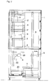
- Figs. 1 and 2 show a transfusion bottle feed apparatus according to the present invention.
- an apparatus body 1 having a rectangular frame is provided with a plural stages of storage shelves 2, a lifter 3, a receiving table 4 and a grip mechanism 5.
- the storage shelves 2 are positioned at almost upper part of the apparatus body 1. Behind the storage shelves 2 is provided a lifting space 6 for the lifter 3 which will be explained hereinafter.
- a plurality of conveyor rollers 8 (first conveyor mechanism) which are driven to rotate by a motor 7 are provided so that a packaging box 9 put on the plurality of conveyor rollers 8 can be conveyed in a back-and-forth direction of the apparatus body 1.
- stoppers 10, 11 are provided in order to prevent the packaging box 9 from dropping off.
- the rear stopper 11 is arranged so as to be horizontally laid by a motor 12.
- the packaging boxes 9 in each of which the same kind of the transfusion bottles 13 are contained are put and stored with the upper surface opened.
- the packaging boxes 9 in which the same kind of the transfusion bottles 13 are contained are stored. Namely, in Fig. 1, the packaging boxes 9 in which "A" of the transfusion bottles 13a are contained are stored in the left column; the packaging boxes 9 in which "B" of the transfusion bottles 13b are contained are stored in the middle column; and the packaging boxes 9 in which "C" of the transfusion bottles 13c are contained are stored in the right column.
- the lifter 3 is arranged so that it can move upward and downward in the lifting space 6 behind the storage shelves 2 and can stop at the same levels as that of the storage shelves 2.
- a plurality of conveyor belts 14 (second conveyor mechanism) the number of which corresponds to that of the storage sections of each storage shelf 2 are provided.
- Each of the conveyor belts 14 is driven to rotate by a motor 15 so that the packaging box 9 put on the conveyor belt 14 can be conveyed in the same direction as that of the conveyor rollers 8 of the storage shelf 2.
- the receiving table 4, as shown in Fig. 4, is disposed at the same level as the lifter 3 moved downward to the lowermost position and at the front side of the liter 3.
- a plurality of conveyor belts 16 (third conveyor mechanism) are provided in the same manner as the conveyor belts 14 of the lifter 3.
- Each of the conveyor belts 16 is driven to rotate by a motor 17 so that the packaging box 9 put on the conveyor belt 17 can be conveyed in the same direction as that of the conveyor belts 14 of the lifter 3.
- the receiving table 4, as shown in Fig. 5, is slidably moved forward by a motor (not shown) on guide rails 18 toward an opening formed on the apparatus body 1.
- levers 19 each of which also serves as a stopper and each of which is arranged so as to be horizontally laid by a motor not shown.
- a conveyor path 21 which passes through the apparatus body 1 and on which a collection container 20 is conveyed in a left-and-right direction.
- the grip mechanism 5 as shown in Figs. 1 and 2, comprises a grip arm 22 which can grip and release the mouth portion of the transfusion bottle 13 from upward, a tilting mechanism 23 which can tilt the grip arm 22 by about 60 degrees, and a moving mechanism not shown which can move the grip arm 22 upward and downward and also move the grip arm 22 in both a back-and-forth direction and a left-and-right direction.
- the collection container 20 is conveyed on the conveyor path 21 and positioned in the transfusion bottle feed apparatus. Then, the lifter 3 is moved upward to the storage shelf 2 on which the packaging boxes 9 that contain the transfusion bottles 13 corresponding to the prescription are stored.
- the conveyor rollers 8 of the storage shelf 2 and the conveyor belts 14 of the lifter 3 are driven to convey the packaging box 9 of the transfusion bottle 13 from the storage shelf 2 to the lifter 3. Consequently, the lifter 3 is moved downward to the lowermost position.
- the conveyor belts 14 of the lifter 3 and the conveyor belts 16 of the receiving table 4 are driven to convey the packaging box 9 of the transfusion bottle 13 from the lifter 3 to the receiving table 4.
- the grip mechanism 5 is driven to grip the transfusion bottle 13 within the packaging box 9 on the receiving table 4.
- the transfusion bottle 13 is moved to the collection container 20 and released above the collection container 20, whereby the transfusion bottle 13 is contained in the collection container 20.
- the transfusion bottle 13 is collected and rapidly fed.
- the grip arm 22 When the transfusion bottle 13 is contained in the collection container 20, as shown in two-dots chain line in Fig. 1, the grip arm 22 is tilted by about 60 degrees by the tilting mechanism 23 of the grip mechanism 5 in a state that the grip arm 22 grips the transfusion bottle 13. With this state kept, the grip arm 22 is moved downward until the transfusion bottle 13 comes into contact with the bottom of the collection container 20. Then, the grip arm 22 releases the transfusion bottle 13 and retreats in a horizontal direction. Thus, the transfusion bottle 13 falls down with the inclined state, reducing the impact and preventing the transfusion bottles below from being damaged.
- the receiving table 4 is slidably moved forward on the guide rails 18 toward the opening of the apparatus body 1, where the lever 19 is laid and the transfer belts 16 are driven to discharge the empty packaging box 9 on the receiving table 4 through the opening of the apparatus body 1.
- the lever 19 when the lever 19 is rose up, the rear portion of the empty packaging box 9 is kicked upward, allowing the empty packaging box 9 to be easily discharged through the opening.
Landscapes
- Physics & Mathematics (AREA)
- General Physics & Mathematics (AREA)
- Health & Medical Sciences (AREA)
- Vascular Medicine (AREA)
- Engineering & Computer Science (AREA)
- Anesthesiology (AREA)
- Biomedical Technology (AREA)
- Heart & Thoracic Surgery (AREA)
- Hematology (AREA)
- Life Sciences & Earth Sciences (AREA)
- Animal Behavior & Ethology (AREA)
- General Health & Medical Sciences (AREA)
- Public Health (AREA)
- Veterinary Medicine (AREA)
- Warehouses Or Storage Devices (AREA)
- Medical Preparation Storing Or Oral Administration Devices (AREA)
- Infusion, Injection, And Reservoir Apparatuses (AREA)
- Specific Conveyance Elements (AREA)
Abstract
Description
Claims (4)
- A transfusion bottle feed apparatuses in which a plurality of transfusion bottles are grouped by their kinds and stored in an apparatus body so that the transfusion bottles can be fed to a patient in accordance with a prescription data, characterized in that:a plural stages of storage shelves on which packaging boxes with the upper surface opened are put and stored, each of the packaging boxes contains same kind of the transfusion bottles, the packaging boxes in which same kind of the transfusion bottles are contained being put on the storage shelves in an up-and-down direction;a first conveyor mechanism provided on each of the storage shelves for conveying the packaging box of the transfusion bottle stored on the storage shelves;a lifter which can move upward and downward and can stop at the same levels as that of the storage shelves;a second conveyor mechanism provided on the lifter for receiving and conveying the packaging box of the transfusion bottle conveyed from the storage shelves by the first conveyor mechanism;a receiving table positioned at the same level of that of the lifter which moved downward to the lowermost position;a third conveyor mechanism provided on the receiving table for receiving and conveying the packaging box of the transfusion bottle conveyed from the lifter by the second conveyor mechanism; anda grip mechanism for gripping the transfusion bottle in the packaging box positioned on the receiving table, conveying to a collection container, releasing the transfusion bottle above the collection container to contain it therein.
- The transfusion bottle feed apparatuses as in claim 1, wherein the grip mechanism is provided with a tilting mechanism for tilting the transfusion bottle gripped by the grip mechanism; and the gripping mechanism moves downward until the transfusion bottle tilted by the tilting mechanism comes into contact with the bottom of the collection container and releases the transfusion bottle to move in the horizontal direction.
- The transfusion bottle feed apparatuses as in claim 1, wherein the receiving table is slidable toward an opening of the apparatus body; and at the position where the receiving table is slid to the opening of the body apparatus, the third conveyor mechanism discharges the empty packaging box on the receiving table through the opening of the apparatus body.
- The transfusion bottle feed apparatuses as in claim 3, further comprising a lever for kicking the rear portion of the empty packaging box upward.
Applications Claiming Priority (2)
| Application Number | Priority Date | Filing Date | Title |
|---|---|---|---|
| JP2001101972A JP4551584B2 (en) | 2001-03-30 | 2001-03-30 | Infusion bottle supply device |
| JP2001101972 | 2001-03-30 |
Publications (3)
| Publication Number | Publication Date |
|---|---|
| EP1246140A2 true EP1246140A2 (en) | 2002-10-02 |
| EP1246140A3 EP1246140A3 (en) | 2003-11-19 |
| EP1246140B1 EP1246140B1 (en) | 2006-01-25 |
Family
ID=18955224
Family Applications (1)
| Application Number | Title | Priority Date | Filing Date |
|---|---|---|---|
| EP02006987A Expired - Lifetime EP1246140B1 (en) | 2001-03-30 | 2002-03-27 | Transfusion bottle feed apparatus |
Country Status (8)
| Country | Link |
|---|---|
| US (1) | US6692211B2 (en) |
| EP (1) | EP1246140B1 (en) |
| JP (1) | JP4551584B2 (en) |
| KR (1) | KR100802557B1 (en) |
| AT (1) | ATE316674T1 (en) |
| CA (1) | CA2379016A1 (en) |
| DE (1) | DE60208834T2 (en) |
| TW (1) | TW527303B (en) |
Cited By (2)
| Publication number | Priority date | Publication date | Assignee | Title |
|---|---|---|---|---|
| KR100802557B1 (en) * | 2001-03-30 | 2008-02-13 | 가부시키가이샤 유야마 세이사쿠쇼 | Sap bottle feeder |
| EP1857382A4 (en) * | 2005-01-13 | 2012-10-17 | Yuyama Mfg Co Ltd | Article dispensing device and method |
Families Citing this family (44)
| Publication number | Priority date | Publication date | Assignee | Title |
|---|---|---|---|---|
| US6883681B1 (en) * | 1998-12-10 | 2005-04-26 | Scriptpro Llc | Automatic dispensing system for unit medicament packages |
| WO2002021402A1 (en) * | 2000-09-06 | 2002-03-14 | Advanced Pharmacy Technologies, L.L.C. | Automated prescription dispensing system and method of use |
| US20040059463A1 (en) * | 2002-06-24 | 2004-03-25 | Scriptpro Llc | Active control center for use with an automatic dispensing system for prescriptions and the like |
| US6910601B2 (en) | 2002-07-08 | 2005-06-28 | Scriptpro Llc | Collating unit for use with a control center cooperating with an automatic prescription or pharmaceutical dispensing system |
| DE10329028A1 (en) * | 2002-07-11 | 2004-01-29 | Ceram Tec Ag Innovative Ceramic Engineering | Preparation of piezoelectric multi layer actuators for e.g. injection valves, provided with heat insulation formed by sintering thick coating mixture of inorganic material and organic binder |
| US7048183B2 (en) | 2003-06-19 | 2006-05-23 | Scriptpro Llc | RFID rag and method of user verification |
| US20040256452A1 (en) * | 2003-06-19 | 2004-12-23 | Coughlin Michael E. | RFID tag and method of user verification |
| US7230519B2 (en) * | 2003-06-19 | 2007-06-12 | Scriptpro Llc | RFID tag and method of user verification |
| WO2004114232A1 (en) * | 2003-06-26 | 2004-12-29 | Riello Technoware Engineering Spa | Device for moving objects contained inside an automatic vending machine |
| US7123989B2 (en) | 2003-07-01 | 2006-10-17 | Asteres, Inc. | System and method for providing a random access and random load dispensing unit |
| CA2533754C (en) | 2003-06-30 | 2013-10-22 | Asteres Inc. | Random access and random load dispensing unit |
| US20060272976A1 (en) * | 2003-07-01 | 2006-12-07 | Asteres, Inc. | Container for use in a random access and random load dispensing unit |
| US20050192705A1 (en) | 2003-07-01 | 2005-09-01 | Asteres Inc. | Random access and random load dispensing unit |
| WO2005009324A2 (en) * | 2003-07-22 | 2005-02-03 | Scriptpro Llc | Fork based transport storage system |
| US7100796B1 (en) | 2003-08-08 | 2006-09-05 | Scriptpro Llc | Apparatus for dispensing vials |
| US20050102163A1 (en) * | 2003-11-06 | 2005-05-12 | Coughlin Michael E. | Method and system for delivering prescriptions to remote locations for patient retrieval |
| US20060005035A1 (en) * | 2004-06-22 | 2006-01-05 | Coughlin Michael E | Keystroke input device for use with an RFID tag and user verification system |
| US7461759B2 (en) * | 2004-07-22 | 2008-12-09 | Scriptpro Llc | Fork based transport storage system for pharmaceutical unit of use dispenser |
| US7988947B2 (en) * | 2004-11-23 | 2011-08-02 | E. I. Du Pont De Nemours And Company | Mesoporous oxide of titanium |
| US7175381B2 (en) * | 2004-11-23 | 2007-02-13 | Scriptpro Llc | Robotic arm for use with pharmaceutical unit of use transport and storage system |
| DE102005058478A1 (en) * | 2005-12-07 | 2007-06-14 | Walter Winkler | Display shelf for e.g. fruit, has shelf board with conveyor belt provided above storage surface on upper side of shelf board and transported in endless loop via end face, where belt is provided with drive |
| US7783379B2 (en) | 2007-04-25 | 2010-08-24 | Asteres, Inc. | Automated vending of products containing controlled substances |
| US9321591B2 (en) | 2009-04-10 | 2016-04-26 | Symbotic, LLC | Autonomous transports for storage and retrieval systems |
| US8594835B2 (en) | 2009-04-10 | 2013-11-26 | Symbotic, LLC | Control system for storage and retrieval systems |
| US11078017B2 (en) | 2010-12-15 | 2021-08-03 | Symbotic Llc | Automated bot with transfer arm |
| US9187244B2 (en) | 2010-12-15 | 2015-11-17 | Symbotic, LLC | BOT payload alignment and sensing |
| US9561905B2 (en) | 2010-12-15 | 2017-02-07 | Symbotic, LLC | Autonomous transport vehicle |
| US8965619B2 (en) | 2010-12-15 | 2015-02-24 | Symbotic, LLC | Bot having high speed stability |
| US8696010B2 (en) | 2010-12-15 | 2014-04-15 | Symbotic, LLC | Suspension system for autonomous transports |
| US9499338B2 (en) | 2010-12-15 | 2016-11-22 | Symbotic, LLC | Automated bot transfer arm drive system |
| US9150119B2 (en) | 2013-03-15 | 2015-10-06 | Aesynt Incorporated | Apparatuses, systems, and methods for anticipating and delivering medications from a central pharmacy to a patient using a track based transport system |
| US9511945B2 (en) | 2012-10-12 | 2016-12-06 | Aesynt Incorporated | Apparatuses, systems, and methods for transporting medications from a central pharmacy to a patient in a healthcare facility |
| JP6523296B2 (en) | 2013-09-13 | 2019-05-29 | シムボティック エルエルシー | Automatic storage and retrieval system |
| JP6423648B2 (en) * | 2014-08-20 | 2018-11-14 | 株式会社椿本チエイン | Cryogenic storage system |
| CN104973375A (en) * | 2015-06-25 | 2015-10-14 | 张家港市华源染织有限公司 | Cloth extraction goods shelf |
| CN105015931A (en) * | 2015-06-25 | 2015-11-04 | 张家港市华源染织有限公司 | Storage rack for extracting cloth |
| CN105035521A (en) * | 2015-07-31 | 2015-11-11 | 无锡市日升化工有限公司 | Chemical barrel storage rack |
| CN106039351A (en) * | 2016-07-27 | 2016-10-26 | 杭州国辰迈联机器人科技有限公司 | Ultraviolet disinfection retaining mechanism of infusion bottles |
| CN106335772B (en) * | 2016-10-29 | 2023-11-10 | 重庆正川医药包装材料股份有限公司 | Bottle arranging machine |
| CA3083095A1 (en) | 2017-11-21 | 2019-05-31 | Fulfil Solutions, Inc. | Product handling and packaging system |
| CN108861273B (en) * | 2018-07-03 | 2024-03-29 | 国网江苏省电力有限公司无锡供电分公司 | Material lifting warehouse |
| CN112722843A (en) * | 2021-01-30 | 2021-04-30 | 南京晶立恒贸易有限公司 | Intelligent logistics storage equipment |
| CN114177373B (en) * | 2021-12-17 | 2023-06-13 | 郑州大学第一附属医院 | Automatic hydrothorax and ascites collecting equipment |
| US12459735B2 (en) | 2023-03-16 | 2025-11-04 | Toyota Motor Engineering & Manufacturing North America, Inc. | Apparatus, system, and method for automating parts delivery |
Family Cites Families (41)
| Publication number | Priority date | Publication date | Assignee | Title |
|---|---|---|---|---|
| CA1039245A (en) * | 1975-05-14 | 1978-09-26 | Leonard P. Falk | Article vendor with elevator |
| US4389157A (en) * | 1981-07-09 | 1983-06-21 | Sps Technologies, Inc. | Retrieval and storage mechanism for use with an automated rotating storage unit |
| JPS61206708A (en) * | 1985-03-07 | 1986-09-13 | Motoda Electronics Co Ltd | Tray delivery apparatus |
| JPS61273345A (en) | 1985-05-15 | 1986-12-03 | 三菱重工業株式会社 | Pallet for bottle |
| JPS6212507A (en) | 1985-07-10 | 1987-01-21 | Mitsubishi Heavy Ind Ltd | Transport of bottles and apparatus thereof |
| US4687119A (en) * | 1985-10-23 | 1987-08-18 | Hubert Juillet | Dispenser for hot and cold products |
| US4896024A (en) * | 1987-10-19 | 1990-01-23 | Diebold, Incorporated | Apparatus for dispensing and accepting return of reusable articles |
| DE3816028A1 (en) * | 1988-05-10 | 1989-11-23 | Dany S Snack Gmbh & Co | DISPENSER FOR BAKED PORTIONED FOOD |
| JPH0260648A (en) * | 1988-08-26 | 1990-03-01 | Central Unie:Kk | Injection automatic dispensing device |
| JP2570421B2 (en) | 1989-05-26 | 1997-01-08 | 富士電機株式会社 | Item information storage device on pallet |
| DE3920405C1 (en) * | 1989-06-22 | 1990-03-29 | Goldschmidt, Sol, Zuerich, Ch | |
| JPH0332012A (en) | 1989-06-29 | 1991-02-12 | Nippon Chemicon Corp | Manufacture of aluminum electrode for electrolytic capacitor |
| JP2903113B2 (en) * | 1989-07-20 | 1999-06-07 | 西部電機株式会社 | How to remove items |
| JPH0362786A (en) | 1989-07-31 | 1991-03-18 | Tamapatsuku Kk | Television receiver |
| JPH0643203B2 (en) | 1989-08-25 | 1994-06-08 | 西部電機株式会社 | Storage facility |
| JPH0822682B2 (en) | 1989-08-30 | 1996-03-06 | 西部電機株式会社 | Article handling equipment |
| JP2805219B2 (en) | 1989-09-12 | 1998-09-30 | 有限会社ニシイ | Sole sole for women's shoes with double layer structure |
| JP3167735B2 (en) * | 1991-04-11 | 2001-05-21 | 株式会社アマダ | Material and product loading / unloading equipment for processing machines |
| FR2699310B1 (en) * | 1992-12-02 | 1995-11-24 | Cyril Sannassee | DEVICE FOR DISPENSING BOTTLES AND RESUMING AUTOMATIC SETTINGS FOR INDUSTRIAL AND DOMESTIC GAS. |
| JPH06293402A (en) | 1993-04-07 | 1994-10-21 | Mitsubishi Heavy Ind Ltd | Robot chuck for automatic operation managing storehouse |
| JP3186899B2 (en) | 1993-06-02 | 2001-07-11 | 株式会社日立製作所 | Stopping position control method and device of picking device, position control method and device of picking device, picking device |
| JPH072313A (en) | 1993-06-18 | 1995-01-06 | Fuji Electric Co Ltd | Flexible individual storage and retrieval device and flexible individual holding hand |
| JPH0788156A (en) | 1993-09-22 | 1995-04-04 | Tokyo Shokai:Kk | Injection preparing machine |
| JP3344850B2 (en) * | 1993-12-28 | 2002-11-18 | 株式会社リコー | Parts supply device |
| US5672040A (en) * | 1994-03-07 | 1997-09-30 | Sony Corporation | Parts feeding apparatus and parts feeding process |
| DE4416103C2 (en) * | 1994-04-19 | 1999-01-07 | Bellheimer Metallwerk Gmbh | high level rack |
| US5533606A (en) * | 1994-09-13 | 1996-07-09 | Yuyama; Shoji | Apparatus for storing and transporting drugs |
| FI100320B (en) * | 1994-12-21 | 1997-11-14 | Rapeli Pekka Eino | Transport and distribution of goods units in ships |
| JPH08319004A (en) * | 1995-05-23 | 1996-12-03 | Bando Chem Ind Ltd | Chemical container replacement device |
| AT405640B (en) * | 1995-12-21 | 1999-10-25 | Knapp Holding Gmbh | PICKING SYSTEM |
| JPH09215729A (en) * | 1996-02-07 | 1997-08-19 | Yuyama Seisakusho:Kk | Ampule replenishing method |
| US5860784A (en) * | 1996-11-05 | 1999-01-19 | Mannesmann Dematic Rapistan Corp. | High volume conveyor accumulator for warehouse |
| US5832693A (en) * | 1997-01-22 | 1998-11-10 | Kabushiki Kaisha Yuyama Seisakusho | Apparatus for collecting ampules |
| JPH1159814A (en) | 1997-08-12 | 1999-03-02 | Kobe Steel Ltd | Automatic picking system |
| DE29813514U1 (en) * | 1998-01-05 | 1998-10-08 | Runneck, Matthias, 67346 Speyer | Vending machine |
| US6883681B1 (en) * | 1998-12-10 | 2005-04-26 | Scriptpro Llc | Automatic dispensing system for unit medicament packages |
| US6325586B1 (en) * | 1999-12-08 | 2001-12-04 | Protosight, Inc. | Automated storage and retrieval system |
| DE19959061A1 (en) * | 1999-12-08 | 2001-06-13 | Hauni Maschinenbau Ag | Method for conveying rod-shaped articles and container conveying device |
| WO2001068484A1 (en) * | 2000-03-16 | 2001-09-20 | Yuyama Mfg. Co., Ltd. | Automatic dispenser for injection-containing members |
| JP4617011B2 (en) * | 2001-03-13 | 2011-01-19 | 株式会社湯山製作所 | Drug storage device |
| JP4551584B2 (en) * | 2001-03-30 | 2010-09-29 | 株式会社湯山製作所 | Infusion bottle supply device |
-
2001
- 2001-03-30 JP JP2001101972A patent/JP4551584B2/en not_active Expired - Fee Related
-
2002
- 2002-03-27 US US10/106,039 patent/US6692211B2/en not_active Expired - Fee Related
- 2002-03-27 DE DE60208834T patent/DE60208834T2/en not_active Expired - Lifetime
- 2002-03-27 EP EP02006987A patent/EP1246140B1/en not_active Expired - Lifetime
- 2002-03-27 CA CA002379016A patent/CA2379016A1/en not_active Abandoned
- 2002-03-27 KR KR1020020016756A patent/KR100802557B1/en not_active Expired - Fee Related
- 2002-03-27 TW TW091106072A patent/TW527303B/en not_active IP Right Cessation
- 2002-03-27 AT AT02006987T patent/ATE316674T1/en not_active IP Right Cessation
Cited By (2)
| Publication number | Priority date | Publication date | Assignee | Title |
|---|---|---|---|---|
| KR100802557B1 (en) * | 2001-03-30 | 2008-02-13 | 가부시키가이샤 유야마 세이사쿠쇼 | Sap bottle feeder |
| EP1857382A4 (en) * | 2005-01-13 | 2012-10-17 | Yuyama Mfg Co Ltd | Article dispensing device and method |
Also Published As
| Publication number | Publication date |
|---|---|
| JP4551584B2 (en) | 2010-09-29 |
| DE60208834D1 (en) | 2006-04-13 |
| KR20020077153A (en) | 2002-10-11 |
| DE60208834T2 (en) | 2006-08-31 |
| US6692211B2 (en) | 2004-02-17 |
| US20020139810A1 (en) | 2002-10-03 |
| TW527303B (en) | 2003-04-11 |
| ATE316674T1 (en) | 2006-02-15 |
| CA2379016A1 (en) | 2002-09-30 |
| KR100802557B1 (en) | 2008-02-13 |
| EP1246140B1 (en) | 2006-01-25 |
| EP1246140A3 (en) | 2003-11-19 |
| JP2002302214A (en) | 2002-10-18 |
Similar Documents
| Publication | Publication Date | Title |
|---|---|---|
| US6692211B2 (en) | Transfusion bottle feed apparatus | |
| AU2005290381B2 (en) | Device for filling a carton | |
| US6971833B1 (en) | Order picking system | |
| CN206456936U (en) | The cargo transfer means and goods storage system of automatic goods storage system | |
| EP0999129B1 (en) | Tablet packing apparatus | |
| US6789996B2 (en) | Medicine feed apparatus | |
| US5615993A (en) | Method of removing articles | |
| CN1261971A (en) | Vending machine to select composition of pack and its method of use | |
| US3547282A (en) | Apparatus for transient handling and storing of articles | |
| US8640747B2 (en) | Medicine filling device | |
| KR20190015245A (en) | An order-sorting machine having an apparatus for filling a group of chemical packs according to an order into each carrier container | |
| US6726056B2 (en) | Medicine feed apparatus | |
| JP2007330411A (en) | Tablet container packing machine | |
| JPH05151443A (en) | Commodity carrying-out device of automatic vending machine | |
| JP4969228B2 (en) | Individual packaging medicine automatic supply equipment | |
| JP2001126132A (en) | Vending machine product storage device | |
| JP2001155234A (en) | Vending machine product storage device | |
| JPH07102897B2 (en) | Article handling method and apparatus | |
| CN117429785A (en) | Automated blood station equipment | |
| JP2003272040A (en) | Vending machine | |
| JPH03100794A (en) | Commodity carrying-out device for automatic vending machine | |
| JP2002128273A (en) | Group of vessels delivery mechanism and vessel conveyance facility | |
| JPH0293791A (en) | Vending machine product conveyance device | |
| JPH0290395A (en) | Vending machine product dispenser structure | |
| JPH03189899A (en) | Automatic vending machine |
Legal Events
| Date | Code | Title | Description |
|---|---|---|---|
| PUAI | Public reference made under article 153(3) epc to a published international application that has entered the european phase |
Free format text: ORIGINAL CODE: 0009012 |
|
| AK | Designated contracting states |
Kind code of ref document: A2 Designated state(s): AT BE CH CY DE DK ES FI FR GB GR IE IT LI LU MC NL PT SE TR |
|
| AX | Request for extension of the european patent |
Free format text: AL;LT;LV;MK;RO;SI |
|
| PUAL | Search report despatched |
Free format text: ORIGINAL CODE: 0009013 |
|
| AK | Designated contracting states |
Kind code of ref document: A3 Designated state(s): AT BE CH CY DE DK ES FI FR GB GR IE IT LI LU MC NL PT SE TR |
|
| AX | Request for extension of the european patent |
Extension state: AL LT LV MK RO SI |
|
| RIC1 | Information provided on ipc code assigned before grant |
Ipc: 7G 07F 11/26 B Ipc: 7G 07F 11/42 A Ipc: 7G 07F 11/16 B |
|
| 17P | Request for examination filed |
Effective date: 20040120 |
|
| AKX | Designation fees paid |
Designated state(s): AT BE CH CY DE DK ES FI FR GB GR IE IT LI LU MC NL PT SE TR |
|
| 17Q | First examination report despatched |
Effective date: 20041203 |
|
| GRAP | Despatch of communication of intention to grant a patent |
Free format text: ORIGINAL CODE: EPIDOSNIGR1 |
|
| GRAS | Grant fee paid |
Free format text: ORIGINAL CODE: EPIDOSNIGR3 |
|
| GRAA | (expected) grant |
Free format text: ORIGINAL CODE: 0009210 |
|
| AK | Designated contracting states |
Kind code of ref document: B1 Designated state(s): AT BE CH CY DE DK ES FI FR GB GR IE IT LI LU MC NL PT SE TR |
|
| PG25 | Lapsed in a contracting state [announced via postgrant information from national office to epo] |
Ref country code: IT Free format text: LAPSE BECAUSE OF FAILURE TO SUBMIT A TRANSLATION OF THE DESCRIPTION OR TO PAY THE FEE WITHIN THE PRESCRIBED TIME-LIMIT;WARNING: LAPSES OF ITALIAN PATENTS WITH EFFECTIVE DATE BEFORE 2007 MAY HAVE OCCURRED AT ANY TIME BEFORE 2007. THE CORRECT EFFECTIVE DATE MAY BE DIFFERENT FROM THE ONE RECORDED. Effective date: 20060125 Ref country code: NL Free format text: LAPSE BECAUSE OF FAILURE TO SUBMIT A TRANSLATION OF THE DESCRIPTION OR TO PAY THE FEE WITHIN THE PRESCRIBED TIME-LIMIT Effective date: 20060125 Ref country code: BE Free format text: LAPSE BECAUSE OF FAILURE TO SUBMIT A TRANSLATION OF THE DESCRIPTION OR TO PAY THE FEE WITHIN THE PRESCRIBED TIME-LIMIT Effective date: 20060125 Ref country code: LI Free format text: LAPSE BECAUSE OF FAILURE TO SUBMIT A TRANSLATION OF THE DESCRIPTION OR TO PAY THE FEE WITHIN THE PRESCRIBED TIME-LIMIT Effective date: 20060125 Ref country code: AT Free format text: LAPSE BECAUSE OF FAILURE TO SUBMIT A TRANSLATION OF THE DESCRIPTION OR TO PAY THE FEE WITHIN THE PRESCRIBED TIME-LIMIT Effective date: 20060125 Ref country code: FI Free format text: LAPSE BECAUSE OF FAILURE TO SUBMIT A TRANSLATION OF THE DESCRIPTION OR TO PAY THE FEE WITHIN THE PRESCRIBED TIME-LIMIT Effective date: 20060125 Ref country code: CH Free format text: LAPSE BECAUSE OF FAILURE TO SUBMIT A TRANSLATION OF THE DESCRIPTION OR TO PAY THE FEE WITHIN THE PRESCRIBED TIME-LIMIT Effective date: 20060125 |
|
| REG | Reference to a national code |
Ref country code: GB Ref legal event code: FG4D |
|
| REG | Reference to a national code |
Ref country code: CH Ref legal event code: EP |
|
| REG | Reference to a national code |
Ref country code: IE Ref legal event code: FG4D |
|
| PG25 | Lapsed in a contracting state [announced via postgrant information from national office to epo] |
Ref country code: IE Free format text: LAPSE BECAUSE OF NON-PAYMENT OF DUE FEES Effective date: 20060327 |
|
| PG25 | Lapsed in a contracting state [announced via postgrant information from national office to epo] |
Ref country code: MC Free format text: LAPSE BECAUSE OF NON-PAYMENT OF DUE FEES Effective date: 20060331 Ref country code: LU Free format text: LAPSE BECAUSE OF NON-PAYMENT OF DUE FEES Effective date: 20060331 |
|
| REF | Corresponds to: |
Ref document number: 60208834 Country of ref document: DE Date of ref document: 20060413 Kind code of ref document: P |
|
| PG25 | Lapsed in a contracting state [announced via postgrant information from national office to epo] |
Ref country code: GB Free format text: LAPSE BECAUSE OF NON-PAYMENT OF DUE FEES Effective date: 20060425 Ref country code: SE Free format text: LAPSE BECAUSE OF FAILURE TO SUBMIT A TRANSLATION OF THE DESCRIPTION OR TO PAY THE FEE WITHIN THE PRESCRIBED TIME-LIMIT Effective date: 20060425 Ref country code: DK Free format text: LAPSE BECAUSE OF FAILURE TO SUBMIT A TRANSLATION OF THE DESCRIPTION OR TO PAY THE FEE WITHIN THE PRESCRIBED TIME-LIMIT Effective date: 20060425 |
|
| PG25 | Lapsed in a contracting state [announced via postgrant information from national office to epo] |
Ref country code: ES Free format text: LAPSE BECAUSE OF FAILURE TO SUBMIT A TRANSLATION OF THE DESCRIPTION OR TO PAY THE FEE WITHIN THE PRESCRIBED TIME-LIMIT Effective date: 20060506 |
|
| PG25 | Lapsed in a contracting state [announced via postgrant information from national office to epo] |
Ref country code: PT Free format text: LAPSE BECAUSE OF FAILURE TO SUBMIT A TRANSLATION OF THE DESCRIPTION OR TO PAY THE FEE WITHIN THE PRESCRIBED TIME-LIMIT Effective date: 20060626 |
|
| NLV1 | Nl: lapsed or annulled due to failure to fulfill the requirements of art. 29p and 29m of the patents act | ||
| REG | Reference to a national code |
Ref country code: CH Ref legal event code: PL |
|
| PLBE | No opposition filed within time limit |
Free format text: ORIGINAL CODE: 0009261 |
|
| STAA | Information on the status of an ep patent application or granted ep patent |
Free format text: STATUS: NO OPPOSITION FILED WITHIN TIME LIMIT |
|
| GBPC | Gb: european patent ceased through non-payment of renewal fee |
Effective date: 20060425 |
|
| 26N | No opposition filed |
Effective date: 20061026 |
|
| PG25 | Lapsed in a contracting state [announced via postgrant information from national office to epo] |
Ref country code: FR Free format text: LAPSE BECAUSE OF FAILURE TO SUBMIT A TRANSLATION OF THE DESCRIPTION OR TO PAY THE FEE WITHIN THE PRESCRIBED TIME-LIMIT Effective date: 20070316 Ref country code: GR Free format text: LAPSE BECAUSE OF FAILURE TO SUBMIT A TRANSLATION OF THE DESCRIPTION OR TO PAY THE FEE WITHIN THE PRESCRIBED TIME-LIMIT Effective date: 20060426 |
|
| PG25 | Lapsed in a contracting state [announced via postgrant information from national office to epo] |
Ref country code: TR Free format text: LAPSE BECAUSE OF FAILURE TO SUBMIT A TRANSLATION OF THE DESCRIPTION OR TO PAY THE FEE WITHIN THE PRESCRIBED TIME-LIMIT Effective date: 20060125 |
|
| PG25 | Lapsed in a contracting state [announced via postgrant information from national office to epo] |
Ref country code: FR Free format text: LAPSE BECAUSE OF FAILURE TO SUBMIT A TRANSLATION OF THE DESCRIPTION OR TO PAY THE FEE WITHIN THE PRESCRIBED TIME-LIMIT Effective date: 20060331 |
|
| PG25 | Lapsed in a contracting state [announced via postgrant information from national office to epo] |
Ref country code: FR Free format text: LAPSE BECAUSE OF FAILURE TO SUBMIT A TRANSLATION OF THE DESCRIPTION OR TO PAY THE FEE WITHIN THE PRESCRIBED TIME-LIMIT Effective date: 20060125 Ref country code: CY Free format text: LAPSE BECAUSE OF FAILURE TO SUBMIT A TRANSLATION OF THE DESCRIPTION OR TO PAY THE FEE WITHIN THE PRESCRIBED TIME-LIMIT Effective date: 20060125 |
|
| PGFP | Annual fee paid to national office [announced via postgrant information from national office to epo] |
Ref country code: DE Payment date: 20120323 Year of fee payment: 11 |
|
| REG | Reference to a national code |
Ref country code: DE Ref legal event code: R119 Ref document number: 60208834 Country of ref document: DE Effective date: 20131001 |
|
| PG25 | Lapsed in a contracting state [announced via postgrant information from national office to epo] |
Ref country code: DE Free format text: LAPSE BECAUSE OF NON-PAYMENT OF DUE FEES Effective date: 20131001 |