EP1246038A2 - Vorrichtung zum Verschliessen einer Fluidrohrleitung - Google Patents
Vorrichtung zum Verschliessen einer Fluidrohrleitung Download PDFInfo
- Publication number
- EP1246038A2 EP1246038A2 EP02290625A EP02290625A EP1246038A2 EP 1246038 A2 EP1246038 A2 EP 1246038A2 EP 02290625 A EP02290625 A EP 02290625A EP 02290625 A EP02290625 A EP 02290625A EP 1246038 A2 EP1246038 A2 EP 1246038A2
- Authority
- EP
- European Patent Office
- Prior art keywords
- valve
- annular
- seat
- auxiliary
- flow
- Prior art date
- Legal status (The legal status is an assumption and is not a legal conclusion. Google has not performed a legal analysis and makes no representation as to the accuracy of the status listed.)
- Withdrawn
Links
- 239000012530 fluid Substances 0.000 title claims abstract description 10
- 238000001816 cooling Methods 0.000 claims abstract description 6
- 239000013013 elastic material Substances 0.000 claims description 4
- 230000002093 peripheral effect Effects 0.000 claims description 3
- XLYOFNOQVPJJNP-UHFFFAOYSA-N water Substances O XLYOFNOQVPJJNP-UHFFFAOYSA-N 0.000 description 13
- 230000000694 effects Effects 0.000 description 2
- 239000012080 ambient air Substances 0.000 description 1
- 230000001174 ascending effect Effects 0.000 description 1
- 239000000498 cooling water Substances 0.000 description 1
- 239000000463 material Substances 0.000 description 1
- 230000000284 resting effect Effects 0.000 description 1
Images


Classifications
-
- G—PHYSICS
- G05—CONTROLLING; REGULATING
- G05D—SYSTEMS FOR CONTROLLING OR REGULATING NON-ELECTRIC VARIABLES
- G05D23/00—Control of temperature
- G05D23/01—Control of temperature without auxiliary power
- G05D23/02—Control of temperature without auxiliary power with sensing element expanding and contracting in response to changes of temperature
- G05D23/021—Control of temperature without auxiliary power with sensing element expanding and contracting in response to changes of temperature the sensing element being a non-metallic solid, e.g. elastomer, paste
- G05D23/022—Control of temperature without auxiliary power with sensing element expanding and contracting in response to changes of temperature the sensing element being a non-metallic solid, e.g. elastomer, paste the sensing element being placed within a regulating fluid flow
Definitions
- the present invention relates to a closure device of a fluid flow pipe, in particular a pipe of a cooling circuit of a motor vehicle engine.
- valves which open and close depending on the temperature of water, under the effect of actuators generally constituted by wax thermostats. Taking into account temperature variations exterior, it is now common to provide between the valve and the sits an increasing flow space in the first part of the valve opening stroke in order to avoid flapping of the valve.
- the object of the present invention is in particular to improve the conditions for the flow of water from cooling at the start of the valve opening stroke by report to headquarters.
- the shut-off device of a flow pipe of a fluid in particular a pipe of a cooling circuit of a motor vehicle engine, comprises a valve connected to a actuator so as to move this valve relative to a annular seat between a closed position in which zones main annulars of the valve and the seat are supported one on the other.
- said seat and said valve have auxiliary parts which are located on the opening direction side of said valve relative to their main annular areas and these parts auxiliary have auxiliary annular zones which are distant from their main annular zones and which, when the valve moves between its closed position and an intermediate position remain in contact with each other by deformation at less than one and provide at least one passage between them fluid flow.
- At least one of said parts auxiliary is preferably made of an elastic material and remains supported on the other auxiliary part when the valve moves between its shutter position and said intermediate position.
- one of said auxiliary parts preferably includes an annular lip forming its annular zone auxiliary and remaining supported on the auxiliary annular zone of the other auxiliary part when the valve moves between its position shutter and said intermediate position.
- said annular lip is preferably elastically deformable.
- At least one of said parts auxiliaries preferably has at least one notch (15) crossing its auxiliary annular zone.
- said valve and said seat have between them, preferably, an increasing flow space when the valve moves away from the seat, at least in its stroke located after said intermediate position.
- the seat preferably has a projecting annular part which is located on the opening direction side of said valve relative to its aforesaid main annular zone, said projecting part of the seat comprising at least one notch constituting said flow passage.
- the valve preferably comprises a annular ring made of an elastic material having its annular zone main aforementioned and, at a distance from this main annular zone, a peripheral annular lip constituting its annular zone aforementioned auxiliary.
- said auxiliary parts are of preferably adapted so that the flow of fluid between said seat and said valve has three successive phases from its position obturation, i.e. a first phase with reduced flow at across said flow passage to the intermediate position above, a second phase of reduced growth flow when said auxiliary annular zones separate and move away and a fast growing flow phase.
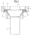
- the closure device 1 shown in the figures is intended for closing a cylindrical pipe 2.
- this shutter device 1 comprises, in line 2, an annular seat 2 adjacent to the line 2 and an assembly movable axially thereto, constituting a valve 3 and comprising a wax thermostat 4 and a ring 5 which is crossed and carried by this themostat 4.
- the ring 5 has an annular peripheral part radial 6 on either side of which is molded a ring 7 in one rubbery material, this part 6 having orifices through 8 for this purpose.
- the thermostat comprises a rod longitudinal 4a, the end of which bears on a support, not shown, and a spring 9 disposed around the body of the thermostat 4 acts between the ring 5 bearing on the ring 7 and a stirrup 10, so as to move the valve 3 closer to the seat 2.
- annular zone main device in the shape of a chamfer 11 of the ring 7 comes resting against a main interior annular zone in the form of chamfer 12 of seat 2.
- seat 2 includes a projecting annular portion 13 which surrounds at a distance the ring 7 of the valve 3 when the latter is in its position closing.
- This annular projecting part 13 has, at a distance of the annular zone 12 of the seat 2, a rounded chamfer 12a so that when the ring 7 of the valve 3 moves away from the annular zone 12 of the seat 2, the annular flow space separating the ring 7 and the protruding part 13 increases.
- the ring 7 Opposite and at a distance from its annular zone 11, the ring 7 has an annular lip 14 that is peripherally projecting and elastically deformable.
- This lip 14 is intended to come and stay elastically in contact, when deformed, on the projecting part 13 of seat 2 when valve 3 moves between its closed position above and an intermediate position in which the ring 7 is still engaged inside the annular projecting part 13 of the seat 2 but at a distance from the annular zone 12 of this seat, as the shows Figure 3.
- the seat 2 and the valve 3 include auxiliary annular zones determined by the projecting part 13 and the lip 14, distinct from the main annular zones 11 and 12 and located on the opening direction of the valve 3 relative to the seat 2.
- the protruding part 13 of the seat 2 has three notches distributed interiors that constitute water flow passages when the lip 14 of the ring 7 is in contact with the projecting part 13 of seat 2.
- the shutter device 1 which has just been described works as follows.
- valve 3 When the water temperature in line 2, around of the body of thermostat 4, is less than a determined value, the valve 3 is in the closed position as described above and as shown in Figures 2 and 4.
- valve 3 ensures, from from its closed position, three successive phases of flow of water, i.e. a first phase with reduced flow through notches 15 to its aforementioned intermediate position, one second reduced growth flow phase through space aforementioned ascending annular from its intermediate position above and a rapidly growing flow phase until its fully open position.
Landscapes
- Physics & Mathematics (AREA)
- Fluid Mechanics (AREA)
- General Physics & Mathematics (AREA)
- Engineering & Computer Science (AREA)
- Automation & Control Theory (AREA)
- Temperature-Responsive Valves (AREA)
- Cooling, Air Intake And Gas Exhaust, And Fuel Tank Arrangements In Propulsion Units (AREA)
Applications Claiming Priority (2)
| Application Number | Priority Date | Filing Date | Title |
|---|---|---|---|
| FR0103330A FR2821913B1 (fr) | 2001-03-12 | 2001-03-12 | Dispositif d'obturation d'une conduite d'ecoulement d'un fluide |
| FR0103330 | 2001-03-12 |
Publications (2)
| Publication Number | Publication Date |
|---|---|
| EP1246038A2 true EP1246038A2 (de) | 2002-10-02 |
| EP1246038A3 EP1246038A3 (de) | 2002-10-09 |
Family
ID=8861003
Family Applications (1)
| Application Number | Title | Priority Date | Filing Date |
|---|---|---|---|
| EP02290625A Withdrawn EP1246038A3 (de) | 2001-03-12 | 2002-03-12 | Vorrichtung zum Verschliessen einer Fluidrohrleitung |
Country Status (2)
| Country | Link |
|---|---|
| EP (1) | EP1246038A3 (de) |
| FR (1) | FR2821913B1 (de) |
Families Citing this family (1)
| Publication number | Priority date | Publication date | Assignee | Title |
|---|---|---|---|---|
| FR2858678B1 (fr) | 2003-08-08 | 2005-09-30 | Renault Sa | Dispositif de regulation progressive de l'ecoulement d'un fluide dans une conduite |
Family Cites Families (5)
| Publication number | Priority date | Publication date | Assignee | Title |
|---|---|---|---|---|
| US4171767A (en) * | 1976-05-21 | 1979-10-23 | Robertshaw Controls Company | Engine cooling system thermostat and method of making the same |
| US4691861A (en) * | 1985-10-25 | 1987-09-08 | Robertshaw Controls Company | Valve construction and method of making the same |
| DE69426027T2 (de) * | 1994-12-09 | 2001-05-17 | Nippon Thermostat Co. Ltd., Kiyose | Thermisch gesteuertes Ventil |
| WO1997011262A1 (en) * | 1995-09-19 | 1997-03-27 | Standard-Thomson Corporation | Thermostat having a movable weir valve |
| FR2769680B1 (fr) * | 1997-10-10 | 1999-12-31 | Vernet Sa | Clapet surmoule, notamment pour thermostat, et thermostat muni d'un tel clapet |
-
2001
- 2001-03-12 FR FR0103330A patent/FR2821913B1/fr not_active Expired - Fee Related
-
2002
- 2002-03-12 EP EP02290625A patent/EP1246038A3/de not_active Withdrawn
Also Published As
| Publication number | Publication date |
|---|---|
| FR2821913A1 (fr) | 2002-09-13 |
| FR2821913B1 (fr) | 2004-04-09 |
| EP1246038A3 (de) | 2002-10-09 |
Similar Documents
| Publication | Publication Date | Title |
|---|---|---|
| EP1106883B1 (de) | Motorangetriebene Thermostatvorrichtung mit thermostatischer Sicherung | |
| WO2008145461A1 (fr) | Module pour un circuit de refroidissement d'un moteur de vehicule automobile | |
| FR2914977A1 (fr) | Ensemble thermostatique de regulation d'un ecoulement de fluide,et procede de fabrication d'un tel ensemble | |
| FR2689600A1 (fr) | Couvercle pour un thermostat de carter. | |
| FR2478242A1 (fr) | Accouplement a fluide, sensible a la temperature | |
| FR3016198A1 (fr) | Vanne thermostatique | |
| FR2833089A1 (fr) | Regulateur de pression du type a volet d'etranglement | |
| BE542491A (de) | ||
| EP0235472A1 (de) | Mischungsthermostatventile für den Flüssigkeitskreislauf bei Verbrennungsmotoren | |
| EP0396479B1 (de) | Hahn mit Kugelküken | |
| EP2048396B1 (de) | Kupplungsmechanismus, insbesondere für Kraftfahrzeuge | |
| EP1246038A2 (de) | Vorrichtung zum Verschliessen einer Fluidrohrleitung | |
| WO2012085436A1 (fr) | Dispositif de commande du débit d'un fluide de refroidissement | |
| WO2021123021A1 (fr) | Dispositif de commande de l'écoulement d'un fluide | |
| EP1607818B1 (de) | Thermostatventil für einen Kühlmittelkreislauf | |
| FR2527372A1 (fr) | Element presentant une memoire de forme et dont les deformations sont obtenues par variation de la temperature | |
| WO2016169958A1 (fr) | Dispositif thermostatique de régulation de la circulation d'un fluide, ainsi que vanne thermostatique comprenant un tel dispositif | |
| FR2701292A1 (fr) | Dispositif obturateur pour circuit d'échappement de moteur à combustion interne. | |
| FR2557632A1 (fr) | Dispositif de refroidissement pour un moteur a combustion interne | |
| WO2016016210A1 (fr) | Vanne thermostatique a manchon | |
| FR3137428A1 (fr) | Vanne thermostatique à manchon | |
| WO2023144175A1 (fr) | Vanne thermostatique | |
| FR3156831A1 (fr) | Arbre rotatif creux comprenant un insert tubulaire | |
| FR2828254A1 (fr) | "amortisseur selon le principe a un seul tube" | |
| FR3103021A1 (fr) | Dispositif thermostatique de régulation de la circulation d’un fluide, ainsi que vanne thermostatique correspondante et procédé de fabrication d’un tel dispositif |
Legal Events
| Date | Code | Title | Description |
|---|---|---|---|
| PUAI | Public reference made under article 153(3) epc to a published international application that has entered the european phase |
Free format text: ORIGINAL CODE: 0009012 |
|
| PUAL | Search report despatched |
Free format text: ORIGINAL CODE: 0009013 |
|
| AK | Designated contracting states |
Kind code of ref document: A2 Designated state(s): AT BE CH CY DE DK ES FI FR GB GR IE IT LI LU MC NL PT SE TR |
|
| AX | Request for extension of the european patent |
Free format text: AL;LT;LV;MK;RO;SI |
|
| AK | Designated contracting states |
Kind code of ref document: A3 Designated state(s): AT BE CH CY DE DK ES FI FR GB GR IE IT LI LU MC NL PT SE TR |
|
| AX | Request for extension of the european patent |
Free format text: AL;LT;LV;MK;RO;SI |
|
| AKX | Designation fees paid | ||
| REG | Reference to a national code |
Ref country code: DE Ref legal event code: 8566 |
|
| 17P | Request for examination filed |
Effective date: 20030616 |
|
| RBV | Designated contracting states (corrected) |
Designated state(s): AT BE CH CY DE DK ES FI FR GB GR IE IT LI LU MC NL PT SE TR |
|
| R17P | Request for examination filed (corrected) |
Effective date: 20030409 |
|
| 17Q | First examination report despatched |
Effective date: 20040427 |
|
| STAA | Information on the status of an ep patent application or granted ep patent |
Free format text: STATUS: THE APPLICATION IS DEEMED TO BE WITHDRAWN |
|
| 18D | Application deemed to be withdrawn |
Effective date: 20041109 |