EP1245998A2 - Device for the exposure of a printed circuit board - Google Patents
Device for the exposure of a printed circuit board Download PDFInfo
- Publication number
- EP1245998A2 EP1245998A2 EP02290697A EP02290697A EP1245998A2 EP 1245998 A2 EP1245998 A2 EP 1245998A2 EP 02290697 A EP02290697 A EP 02290697A EP 02290697 A EP02290697 A EP 02290697A EP 1245998 A2 EP1245998 A2 EP 1245998A2
- Authority
- EP
- European Patent Office
- Prior art keywords
- light
- exposed
- light strip
- panel
- homogeneous
- Prior art date
- Legal status (The legal status is an assumption and is not a legal conclusion. Google has not performed a legal analysis and makes no representation as to the accuracy of the status listed.)
- Withdrawn
Links
Images


Classifications
-
- G—PHYSICS
- G03—PHOTOGRAPHY; CINEMATOGRAPHY; ANALOGOUS TECHNIQUES USING WAVES OTHER THAN OPTICAL WAVES; ELECTROGRAPHY; HOLOGRAPHY
- G03F—PHOTOMECHANICAL PRODUCTION OF TEXTURED OR PATTERNED SURFACES, e.g. FOR PRINTING, FOR PROCESSING OF SEMICONDUCTOR DEVICES; MATERIALS THEREFOR; ORIGINALS THEREFOR; APPARATUS SPECIALLY ADAPTED THEREFOR
- G03F7/00—Photomechanical, e.g. photolithographic, production of textured or patterned surfaces, e.g. printing surfaces; Materials therefor, e.g. comprising photoresists; Apparatus specially adapted therefor
- G03F7/20—Exposure; Apparatus therefor
- G03F7/2022—Multi-step exposure, e.g. hybrid; backside exposure; blanket exposure, e.g. for image reversal; edge exposure, e.g. for edge bead removal; corrective exposure
- G03F7/2032—Simultaneous exposure of the front side and the backside
-
- G—PHYSICS
- G03—PHOTOGRAPHY; CINEMATOGRAPHY; ANALOGOUS TECHNIQUES USING WAVES OTHER THAN OPTICAL WAVES; ELECTROGRAPHY; HOLOGRAPHY
- G03F—PHOTOMECHANICAL PRODUCTION OF TEXTURED OR PATTERNED SURFACES, e.g. FOR PRINTING, FOR PROCESSING OF SEMICONDUCTOR DEVICES; MATERIALS THEREFOR; ORIGINALS THEREFOR; APPARATUS SPECIALLY ADAPTED THEREFOR
- G03F7/00—Photomechanical, e.g. photolithographic, production of textured or patterned surfaces, e.g. printing surfaces; Materials therefor, e.g. comprising photoresists; Apparatus specially adapted therefor
- G03F7/20—Exposure; Apparatus therefor
- G03F7/2002—Exposure; Apparatus therefor with visible light or UV light, through an original having an opaque pattern on a transparent support, e.g. film printing, projection printing; by reflection of visible or UV light from an original such as a printed image
- G03F7/2008—Exposure; Apparatus therefor with visible light or UV light, through an original having an opaque pattern on a transparent support, e.g. film printing, projection printing; by reflection of visible or UV light from an original such as a printed image characterised by the reflectors, diffusers, light or heat filtering means or anti-reflective means used
-
- G—PHYSICS
- G03—PHOTOGRAPHY; CINEMATOGRAPHY; ANALOGOUS TECHNIQUES USING WAVES OTHER THAN OPTICAL WAVES; ELECTROGRAPHY; HOLOGRAPHY
- G03F—PHOTOMECHANICAL PRODUCTION OF TEXTURED OR PATTERNED SURFACES, e.g. FOR PRINTING, FOR PROCESSING OF SEMICONDUCTOR DEVICES; MATERIALS THEREFOR; ORIGINALS THEREFOR; APPARATUS SPECIALLY ADAPTED THEREFOR
- G03F7/00—Photomechanical, e.g. photolithographic, production of textured or patterned surfaces, e.g. printing surfaces; Materials therefor, e.g. comprising photoresists; Apparatus specially adapted therefor
- G03F7/20—Exposure; Apparatus therefor
- G03F7/2002—Exposure; Apparatus therefor with visible light or UV light, through an original having an opaque pattern on a transparent support, e.g. film printing, projection printing; by reflection of visible or UV light from an original such as a printed image
- G03F7/201—Exposure; Apparatus therefor with visible light or UV light, through an original having an opaque pattern on a transparent support, e.g. film printing, projection printing; by reflection of visible or UV light from an original such as a printed image characterised by an oblique exposure; characterised by the use of plural sources; characterised by the rotation of the optical device; characterised by a relative movement of the optical device, the light source, the sensitive system or the mask
-
- G—PHYSICS
- G03—PHOTOGRAPHY; CINEMATOGRAPHY; ANALOGOUS TECHNIQUES USING WAVES OTHER THAN OPTICAL WAVES; ELECTROGRAPHY; HOLOGRAPHY
- G03F—PHOTOMECHANICAL PRODUCTION OF TEXTURED OR PATTERNED SURFACES, e.g. FOR PRINTING, FOR PROCESSING OF SEMICONDUCTOR DEVICES; MATERIALS THEREFOR; ORIGINALS THEREFOR; APPARATUS SPECIALLY ADAPTED THEREFOR
- G03F7/00—Photomechanical, e.g. photolithographic, production of textured or patterned surfaces, e.g. printing surfaces; Materials therefor, e.g. comprising photoresists; Apparatus specially adapted therefor
- G03F7/20—Exposure; Apparatus therefor
- G03F7/2002—Exposure; Apparatus therefor with visible light or UV light, through an original having an opaque pattern on a transparent support, e.g. film printing, projection printing; by reflection of visible or UV light from an original such as a printed image
- G03F7/2014—Contact or film exposure of light sensitive plates such as lithographic plates or circuit boards, e.g. in a vacuum frame
-
- H—ELECTRICITY
- H05—ELECTRIC TECHNIQUES NOT OTHERWISE PROVIDED FOR
- H05K—PRINTED CIRCUITS; CASINGS OR CONSTRUCTIONAL DETAILS OF ELECTRIC APPARATUS; MANUFACTURE OF ASSEMBLAGES OF ELECTRICAL COMPONENTS
- H05K3/00—Apparatus or processes for manufacturing printed circuits
- H05K3/0073—Masks not provided for in groups H05K3/02 - H05K3/46, e.g. for photomechanical production of patterned surfaces
- H05K3/0082—Masks not provided for in groups H05K3/02 - H05K3/46, e.g. for photomechanical production of patterned surfaces characterised by the exposure method of radiation-sensitive masks
Definitions
- the present invention relates to a device for insulating at at least one side of a panel, in particular for a circuit panel printed.
- Such devices make it possible to manufacture printed circuits from a panel coated with photosensitive material in front of which comes to place a snapshot including the tracks to generate on the circuit printed. A light beam scanning the image then allows to insulate the entire panel.
- each light beam is in a cone of revolution having an axis more or less inclined with respect to the surface to insolate, called declination.
- the half angle at the top of the cone represents collimation which accounts for the parallelism between the light rays.
- the object of the invention is to provide an insolation device which improves the insolation of a surface by sweeping, in particular for the manufacture of printed circuits, by providing a strip light presenting, compared to the panel, both a good incidence and good homogeneity.
- Such a device makes it possible to produce printed circuits, the density of conductive tracks is very important and requires a layout precise and end of the tracks and therefore perfect insolation of the surface to insolated.
- the size of the conductive tracks of the printed circuits that we seek to achieve with such a device is between 25 microns and 50 ⁇ m and their spacing is of the same order of magnitude.
- the quality of development i.e. removing the part of the photosensitive material that covers the surface to be exposed so as not to cover future tracks during the engraving, and ultimately the quality of the engraving, depends on the transformation the photosensitive material, transformation which is linked to the amount of light energy received.
- the light beam is not homogeneous, it causes a transformation heterogeneous of this photosensitive material and therefore an imprecise line of tracks which can go as far as interruptions in the latter.
- the light strip the set of light beams which arrive on the surface to be exposed and the angle average incidence corresponding to the angle measured in any plane substantially transverse to the plane of the surface to be exposed under which the half of the luminous flux must reach the surface, the other half being able to arrive from any angle.
- each light beam is in a cone of axis revolution substantially perpendicular to the plane of the surface to insolated.
- the apex half-angle that represents the collimation is less than or equal to the average angle of incidence.
- this involves moving the light strip relative to the surface to insolate or vice versa, in the direction transverse to the length of the light strip to scan the entire surface.
- Scan direction of the panel corresponds to the direction of one side of the panel. So in generating a light strip in a first direction parallel to one of the sides of the panel, one sweeps according to one second direction, substantially transverse to this first direction.
- the scanning time is all the more reduced when the use of a narrow light brush and its flux is all the higher than in the case of global insolation.
- the greater the height of the quadrilateral the longer the time scan is short.
- the greater this height the more difficult to get a low incidence light that is collimated and homogeneous throughout the quadrilateral and the less the luminous flux is important. It is therefore necessary to find a compromise.
- a first aspect of the present invention is to provide a device which improves the insolation of a surface, in particular for the manufacture of printed circuits, from a processing of a light beam emitted by a single fixed light source.
- the scanning is all the more rapid that it is carried out according to a direction parallel to the width of the panel, i.e. when the light strip is parallel to the direction of the length of the panel.
- the length of the light strip is at least equal to the length of the longest side of the panel and the sweep is made according to the shortest side.
- the length of the light strip is at least equal to the length of the panel and scanning is done in the direction parallel to the width of the panel.
- the entire optical system is fixed at so that the optical means which they comprise are not subjected to inadvertent misadjustment which can lead to degradation of the beam homogeneous and collimated light which emerges from this set.
- the light At the input of the integrator-collimator assembly placed after the light source, the light is neither collimated nor distributed homogeneously, while at the output, it is distributed homogeneously, for example with a smaller difference ⁇ 10% for a light band of 780 ⁇ 170 mm 2 and collimated with an average angle of incidence less than 2 °, preferably less than 1 °.
- the integrator-collimator assembly advantageously comprises a first processing optic intended to distribute the light of substantially homogeneous and a second processing optic, said second processing optic being arranged after said first processing optic and being intended to collimate light.
- each lens has a specific role (collimation and declination or homogenization).
- the first processing optic is disposed on the one hand at the second focus of said reflector, so that said first processing optic makes it possible to process said light beam entering it in a homogeneous outgoing light beam, and on the other hand, at focus object of said second processing optic, so that this last allows to treat said homogeneous light beam entering it in a homogeneous and collimated beam.
- the light being homogeneous the variation of the power of the insolation at all points of the light strip is controlled and does not not exceed the extreme values that could damage the tracks.
- the light being collimated the light rays are parallel to each other and all arrive with an angle of incidence less than 2 °.
- the integrator-collimator assembly further includes advantageously a first cover placed in the vicinity of said first optic and a second cover placed in the vicinity of said second optical.
- the first cover eliminates part of the radiation bright (not homogeneous, not collimated) having an average incidence too far from the mean direction of propagation at the exit of the reflector, while the second cover has the same function for the homogeneous light beam which has passed through the first optic of treatment.
- These two caches allow you to trim the collimation by twice removing excessively divergent radiation before entry in the second perspective intended for collimation. The latter is then all the more effective as these divergent radiations are eliminated.
- the temperature of the photograph is a determining factor in the quality of the realization of the printed circuit, because any gradient of temperature causes a distortion of the picture and therefore of the layout of tracks. For example, a simple temperature difference of 2 ° C results in a image distortion.
- the device advantageously comprises a dichroic mirror.
- Infrared is not useful for sunstroke, but entraining a heating of the neighboring elements and in particular of the stereotype, it is advantageous that the heat filter allows the beam to be separated bright between infrared and ultraviolet and therefore to insulate the panel with a "cold" light, that is to say essentially composed ultraviolet.
- the shaping means comprise a first mirror which is divergent and convex and a second mirror which is converging and concave, successively arranged at the outlet of said integrator-collimator set.
- the light beam is homogeneous and collimated, on the other hand, it does not yet appear under forms a strip of light, but extends in two directions usually in the form of a rectangle much smaller than that desired to scan along the length of one side of the sign.
- the first mirror will allow the beam to be collimated luminous in the plane of the mirror by making it diverge in one of the two directions for spreading the light beam according to a light strip of longer than its original length.
- the second mirror will re-collimate this strip luminous in this same plane by making it converge in this same direction so that the light strip has collimation properties identical to those of the light beam entering the focusing system in shape.
- the homogeneity of the light beam and therefore of the strip light remains unchanged throughout the shaping.
- the position of the mirrors in relation to the integrator-collimator assembly does not influence the properties of the light strip, but understands that their relative position in relation to each other, in particular their spacing, as well as their characteristics, determine the geometry of the light strip.
- the length of said light strip homogeneous and collimated is a function of the distance between said mirrors converge and diverge, and radii of curvature of these last and in particular of the radius of curvature of the divergent mirror.
- the height of the light strip depends on the characteristics of the collimating lens and its support. This height of the light strip is only slightly affected by converging mirrors and divergent.
- the displacement means advantageously include a plane and movable deflection mirror in the plane defined by the axes of the face of the panel to be exposed.
- This deflection mirror has no effect on the properties of the tape light and is placed at the output of the optical system that allowed the processing and shaping of the light beam.
- This deflection mirror is the only mobile part of the device and allows successive insolation by scanning, the entire surface by returning a light strip mobile in translation towards the panel to be exposed.
- the dimensions of the deflection mirror are of course adapted to the length of the desired light strip so as not to cause involuntary decrease in the latter.
- the geometry of the light strip being directly linked to the optical shaping system chosen, so it can be easily changed.
- the source advantageously is arranged at the first focus of the reflector.
- it is preferably its arc which is placed at the first focus of the reflector.
- a second aspect of the invention is to provide a device which improves the insolation of a surface, in particular for the manufacture of printed circuits, from a mobile light source.
- the very shape of the reflector determines the properties and the geometry of the light beam.
- said first parable is located in a first plane defined by the axes comprising said scanning direction and said second parable is located in a second plane defined by axes comprising said scanning direction and substantially transverse foreground audit.
- the reflector is advantageously formed by two parts symmetrical.
- the reflector advantageously comprises a central opening.
- the optical system advantageously comprises five light boxes aligned in the direction transverse to said scanning direction, which will be moved in translation, in the scanning direction, or in the direction substantially transverse to the length of the light strip so as to sweep the entire panel.
- the average incidence obtained with five medium arc lamps is approximately 11 °.
- Medium arc lamps make collimating the beam more delicate, but facilitates the superimposition of light sources.
- the number of light boxes should be adjusted and their luminous power, as well as the length of their respective arc and possibly modify the reflector.
- the spacing of the boxes is preferably 145 mm, with adjustment possibilities in the longitudinal direction of the light strip to compensate for inaccuracies in the realization of light boxes.
- the strip collimated light advantageously forms on the surface to be exposed, at a given moment, a quadrilateral with a height between 100 mm and 150 mm and of length at least equal to the length of one of the sides of the surface to be exposed.
- said light source advantageously comprises an electric arc discharge lamp medium or short arc.
- short arcs are less than 10 mm and the medium arcs are between 10 mm and 25 mm. Above 25 mm, we usually speak of an arc lamp long. The shorter the arc of the lamp, the better the collimation; however, the lamp supply is more sophisticated when the arc is short.
- the light strip advantageously has an average angle of incidence less than or equal to 2 ° or 15 °.
- the device also advantageously includes means for calibrating the light source or each of the sources bright independently of one another in the presence of several light sources.
- the calibration means advantageously comprise a single sensor that one comes to place successively in front of each light source. From of the light intensity recorded for a light source, the signal from sensor will allow to control, via a loop control, regulation of the light source supply corresponding and therefore of its emitted power.
- a uniform power of the light strip is obtained. Knowing the average value of this power and the nature of the surface to be exposed, a computer of the device regulates the scanning of the light strip in adapting the speed of movement of the light strip to obtain the desired exposure conditions as a function of the power bright and the nature of the surface to be exposed.
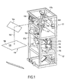
- the exposure device intended for the manufacture of printed circuit shown in FIGS. 1 to 6 has an optical system which is composed of a discharge lamp and of various optical elements.
- the lamp and a device for treatment and shaping of the light beam emitted by the lamp, as well as the panel to be exposed are fixed, and a single optical element, in this case a deflection mirror, allows the surface to be scanned of the panel to be exposed.
- FIG. 1 is an overall view of such a device comprising a panel 120 to be exposed, an optical system S 1 making it possible to process and band-form a light beam emitted by a light source 112.
- the device comprises two optical systems S 1 and S 2 making it possible to process and band-form two light beams emitted respectively by two light sources 112 and 112 'which are arranged side by side to expose the panel on these two faces.
- two similar optical systems S 1 and S 2 are then controlled simultaneously or independently depending on the device chosen.
- the light sources 112 and 112 ′ are arc lamps, for example of the Xenon Mercury type, it is necessary to orient them upwards to ensure their operation.
- the two lamps 112 and 112 ' are oriented in the same direction.
- the processing and shaping system S 1 respectively S 2 , is specific to each lamp 112, respectively 112 ', and is arranged on either side of the lamps 112 and 112' symmetrically.
- the exposure device includes a plurality of deflection mirrors, which do not process the light beam, but make it possible to form elbows in the device and in particular in the processing and shaping system. S 1 .
- mirrors are preferably flat return mirrors simple. They have no action in the treatment of the beam or in its shaping. However, it is preferable that they be treated to be dichroic, whereby they serve as a heat filter by separating the light beam between infrared and ultraviolet. Indeed, such surface treatment allows about 97% of the radiation to be reflected ultraviolet, while passing around 70% of the radiation infrared. Infrared is not useful for sunstroke, but entraining heating the plate (not shown) and surrounding elements, in especially optics, we understand that it is advantageous to separate it at earlier of the light beam and in particular before it crosses the processing and shaping system.
- FIG. 2 schematically shows such an optical system which comprises the short-arc discharge lamp 112, for example with a power of 5 kW or 8 kW, placed at the first focus 122 'of an elliptical reflector 116.
- a 5 kW lamp 112, having an arc of 3 ⁇ 3 ⁇ 7 mm 3, will be used .
- Z II Z II ' be the axis along which the different optical elements are placed, corresponding to the axis of revolution of the reflector 116 formed by a portion of ellipsoid and passing through the two focal points 122' and 124 'of said reflector 116.
- the axis Z II Z II ' is substantially vertical and corresponds to the axis of propagation of the light beam leaving the lamp 112 and the reflector 116.
- Two axes X II X II ' and Y II Y II ' are substantially perpendicular to the 'axis Z II Z II ' so as to define an orthogonal coordinate system.
- first deflection mirror 117 1 which is preferably cooled by a cooling system by blowing cold air 119.
- This first deflection mirror 117 1 is placed at 45 ° above the lamp 112 and returns the light beam I to a second deflection mirror 117 2 (see FIGS. 1 and 2).
- This second deflection mirror 117 2 is preferably oriented upwards at 45 °, so that the light beam I is reflected towards the input of the processing and shaping system, which begins with an integrator-collimator assembly 151.
- This integrator-collimator assembly 151 shown in detail in FIG. 3, comprises an assembly of different diopters allowing on the one hand, to average the illumination and to distribute the light intensity to make it homogeneous and on the other hand, to collimate it.
- the axis of the integrator-collimator assembly 151 coincides with the axis Z II Z II 'and comprises at its input 151A a first processing optic, in this case an integrating lens 150, and at its output 151B, a second processing optic, in this case a collimating lens 156.
- a first processing optic in this case an integrating lens 150
- a second processing optic in this case a collimating lens 156.
- Each of these lenses 150, respectively 156 is arranged in a support 152, respectively 154.
- the two supports 152 and 154 which are preferably covers, are placed substantially perpendicular to the axis Z II Z II ', so as to eliminate the radiation having an incidence too far from the mean direction of propagation at the outlet of the reflector 116 and so that the optical axis of the integrator-collimator assembly 151 is coincident with the axis Z II Z II 'to obtain good variation of the beam on the surface to be exposed.
- the integrating lens 150 is a convex cylindrical lens, of curvature oriented towards the collimating lens 156 and of radius of R150 curvature between 30 mm and 40 mm, preferably substantially equal to 35 mm.
- the integrating lens 150 is placed in the second focal point 124 ′ of the reflector 116.
- the light rays I are in the form of a cone of revolution whose height is substantially on the axis Z II Z II '.
- the light beam I is neither homogeneous nor collimated, at exit, the light beam II is homogeneous with a deviation of less than ⁇ 10%.
- the light beam II is also very slightly collimated by the support 152.
- This light beam II follows its path towards the collimating lens 156, which in this case is a spherical lens of curvature oriented towards the exit of the integrator-collimator assembly 151 and whose radius of curvature R 156 is between 150 mm and 200 mm, preferably substantially equal to 170 mm.
- the collimating lens 156 which in this case is a spherical lens of curvature oriented towards the exit of the integrator-collimator assembly 151 and whose radius of curvature R 156 is between 150 mm and 200 mm, preferably substantially equal to 170 mm.
- the spherical lens 156 is moved away from the spherical lens 152 so that the latter is at the focus object 156 'of the lens spherical 156.
- the light beam III is collimated with an average angle of incidence of the order of 1 °.
- the two focal points 124 'and 156' are combined and the lens spherical 156A and the reflector 116 are arranged on either side of the cylindrical lens 152. Consequently, at the outlet of the assembly integrator-collimator 151, the light beam III is homogeneous with a difference of less than ⁇ 10% and collimated.
- the focal points of the lenses 150 and 154 of the integrator-collimator assembly 151 are arranged on the same axis as that of the second focal point 124 'of the lamp 112, that is to say along the axis Z II Z' II , so that the light beam has the smallest possible declination allowing it to expose the surface of the panel to be exposed substantially perpendicularly.
- the light beam III is homogeneous with a deviation of less than ⁇ 10% and has an average angle of incidence of the order of 1 °.
- a third deflection mirror 117 3 is arranged at the outlet of the integrator-collimator assembly 151 to form the last bend in the light path III.
- the shaping means include shaping optics placed immediately after this third deflecting mirror 117 3 , make it possible to successively de-collimate by causing the light beam to diverge, then re-collimating the light flux III again to obtain a light strip 162.
- a first shaping optic in this case a divergent mirror 158
- a second shaping optic form in this case a converging mirror 160
- the two mirrors 158 and 160 are facing each other, preferably inclined as much as possible towards the horizontal plane (X II X ' II , Y II Y' II ) to avoid optical aberration.
- the two mirrors 158 and 160 are spaced less than 45 ° from the axis Y II Y ' II .
- the divergent mirror 158 is a convex mirror of curvature oriented towards the converging mirror 160 and whose radius of curvature R 158 is preferably between 150 mm and 200 mm.
- the converging mirror 160 it is a concave mirror with a curvature oriented in the same direction as that of the divergent mirror 158 and with a radius of curvature R 160 , preferably between 1,200 mm and 1,500 mm.
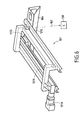
- the two mirrors 158 and 160 make it possible to obtain a light strip 162 (shown in FIG. 2) of length L 162 (shown in FIG. 4).
- the length L 162 is a function of the radius of curvature R 158 of the divergent mirror 158 and the spacing d between the two divergent mirrors 158 and converge 160.
- the width or height H 162 of the light strip 162 for its part depends on the geometric characteristics of the cover 154 and in particular of those of the spherical lens 156.
- the radius of curvature of the mirror 160 can have a small effect on the length L 162 of the light strip. For industrial reasons, this radius of curvature remains constant.
- a fourth deflection mirror 164 is placed opposite the converging mirror 160, so as to return the light strip towards the surface 118 of the panel to be exposed 120 which is placed in the horizontal plane (X II X ' II , Y II Y' II ).
- this fourth deflection mirror 164 is intended to return all or part of this length L 162 .
- the length L 126 of a light strip 126 is obtained which arrives on the surface to be exposed 118 of the printed circuit panel 120 held in a frame (not shown).
- this fourth deflection mirror 164 is the only optical element which is mobile in the device. It is understood that the surface 118 of the panel can be arranged differently.
- the scanning is carried out according to the width of the surface to be exposed, that is to say according to the axis Y II Y II '.
- the scanning is always carried out transversely to the longitudinal direction of the light strip, this scanning direction preferably being parallel to the width or at least the length of the surface to be exposed.
- the fourth deflection mirror 164 is at 45 ° relative to the axis Y II Y ′ II , so as to return the light strip to the surface 118 to be exposed in the plane defined by the axes X II X II 'and Y II Y II '.
- the width of the mirror 164 will be at least equal to the width I 118 of the surface 118 to be exposed. To expose a different surface, it suffices to change the mirror 164 or to vary the parameters of the shaping means.
- the mirror 164 must be adjusted angularly with respect to the vertical and horizontal planes by means not shown in such a way that during its movement, it remains parallel to the panel.
- the speed of movement of the mirror 164 conditions the quality and the duration of sunshine.
- the distance between the two elements increases with during scanning. It would therefore be desirable to adapt the speed of scanning, to obtain a higher quality illumination homogeneity of the entire surface to be exposed throughout the exposure.
- the homogeneity conditions set out above can be satisfied.
- a photometric sensor 138 (shown in Figure 6) sensitive to ultraviolet UV radiation is placed in the luminous flux in place of the panel to be exposed and connected to the automaton of the insolation device (not shown).
- the value of the measured flux power is sent to the controller, which calculates the speed displacement as a function of this luminous power of the flux and parameters of the surface 118 to be exposed, in particular according to the sensitivity of the material, parameters that the operator will have indicated.
- a laser is advantageously placed at the location of the panel to be exposed emitting a visible light beam towards one of the light sources 112 or 112 ′ (FIG. 1) for mechanically adjusting, by means of displacement not shown, the position of each lamp and therefore of each reflector to ensure the correct positioning of the optical axis of each integrator-collimator assembly of each of the systems S 1 and S 2 on the axis Z II Z ' II .
- This calibration is only done during the assembly of the device.
- these displacement means 121 cooperating with the device for example comprise a variable speed motor 121A which drives a belt with two pulleys 121B and a support 121D movable relative to the rails 121C on which the mirror 164 is fixed. All types of known means of travel can be used to move the mirror 164.
- the speed of the displacement means is variable for compensate for the loss of light power due to the progressive spacing of the mirror 164 with respect to the lamp 112.
- a starting speed V Max determined when the mirror 164 is closest to the lamp 112 (at the start of the sunshine), will regularly decrease until reaching a minimum value V MIN , when the scanning of the entire surface 118 is finished.
- the adaptation means comprise a servo loop programmed in the automaton which makes it possible to calculate and adapt the speed of the mirror 164.
- a significant downtime is essential (several ten minutes) before being able to relight the lamps, especially to ensure that they have sufficiently cooled.
- the downtime also includes the necessary time to stabilize the lamps so that the light is emitted homogeneously.
- the life of a lamp is inversely proportional to the number of times the lamp is on and off.
- the device comprises a flap (not shown) which can be arranged in the vicinity of the cylindrical lens 152 for mask the radiation without having to turn off the lamp 112.
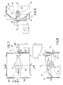
- the exposure device intended for the manufacture of printed circuit shown in FIGS. 7 to 12 comprises an optical system which is composed of a set of light boxes each comprising a specially shaped reflector and a discharge lamp provides a collimated light strip and homogeneous.
- the entire optical system, in particular the light source, is mobile and the panel is fixed.
- Figure 7 shows such a light box 10 which comprises a medium arc discharge lamp 12, preferably of length 20 mm and power 500 W.
- the lamp 12 is placed in a housing 14 in which a reflector 16 has been placed.
- axis X I X I ' as the horizontal axis corresponding to the direction of the width of the surface 18 of the panel to be exposed 20 disposed substantially vertically (shown in FIG. 10 without the plate or the holding frame ), it suffices to move the light box along the axis Y I Y I ', substantially transverse to the axis X I X I ' to scan the entire surface 18.
- the reflector 16 has a surface formed by a first parabola 24 in the vertical plane defined by the axes Y I Y I 'and Z I Z I ' (represented in FIG. 9) and a second parabola 22 in the horizontal plane defined by the axes X I X I 'and Z I Z I ' (shown in Figure 8), having respectively a first focus 24 'and a second focus (not shown) on the axis Z I Z I '.
- the lamp 12 is placed on the first focus 24 '.
- the light rays are therefore preferably sent along the axis Z I Z I '.
- the correct positioning of the lamp 12 in such a reflector 16 conditions the collimation and the declination of the light beam.
- the reflector 16 is produced in two parts 16A and 16B symmetrical with respect to the plane horizontal.
- the reflector has a central opening 16C which is made in the two parts 16A and 16B of the reflector 16.
- the two parts 16A and 16B are not contiguous, but separated from each other by said opening 16C.
- This opening 16C has a defined adequate shape according to the geometry of the lamp 12.
- a length L 26 equal to the width I 18 of the surface 18, preferably 635 mm and a height H 26 between 100 mm and 150 mm, preferably 130 mm, it is preferable to place five light boxes 10 as defined above.
- the panel 20 is arranged substantially at vertically, just align the five light boxes 10 along the axis horizontal to form the light strip 26.
- the light boxes 10 are separated from each other by a nominal distance preferential of 145 mm, it is this distance between the light boxes which conditions the homogeneity of the light beam.
- a setting of the position of each light box 10 compensates for errors for making the light box 10.
- this adjustment can have an amplitude of ⁇ 5 mm around the nominal position.
- the light strip 26 has an average angle of incidence of the order of 11 ° and a deviation in the uniformity of the illumination of ⁇ 10% from the average value which is around 120 mW. cm -2 . In fact, half of the flux arrives on the surface 18 with an angle of incidence less than 11 °.
- the set of light boxes 10 is arranged on a support 28 movable in translation, in the horizontal plane, to allow adjustment the distance between all of the light boxes 10 and the panel 20 to to be exposed, depending on the position of the surface to be exposed which depends on the position of the retaining frame (not shown).
- This distance from the center from the lamp to the panel is preferably 180 mm. This distance determines the quality of the homogeneity of the light strip.
- the support 28 is, for example, arranged on a rail comprising the part female 30 of a dovetail which slides on the fixed male part 32 on a drive support 34 movable in translation in the direction vertical, corresponding to the scanning direction.
- the means of displacement include a drive system training support 34.
- the device comprises a flap 36 fixed on the support 28 capable of rotate in front of the lamps 12.
- the closed position (during a change of panel 20 for example), as shown in the figure 10, the flow of the light strip 26 is interrupted, while the lamps 12 can stay on.
- the flap 36 is shown in position open, during the exposure of a panel 20 (not shown) on the Figure 11.
- the use of such a shutter 36 thus makes it possible to avoid switching off the lamps 12 between each change of panels 20 to be exposed and this made to reduce the manufacturing time of the printed circuit.
- the speed of movement of this drive support 34 determines the quality and duration of the sunshine. To determine this speed, the operator introduces the characteristics of the surface to be exposed, particularly the sensitivity of the material, in a computer of the automaton of the insolation device (not shown). Travel speed is determined at each change of surface type 18 of the panels 20 to be exposed.
- the automaton calculates the light power of the light strip 26 from the light output of each lamp 12.
- Calibration means 38 comprising a calibration cell 40 and a dichroic 42 arranged on a mobile support 44.
- the means of calibration are connected to the automation of the insolation device (no shown), so as to provide the light output of the lamp 12 that we want to calibrate.
- the automaton adjusts the power intensity of the lamp 12, until obtaining the desired power measured by the calibration means 38.
- the calibration of the lamps 12 is made during the start-up of the device for controlling the stabilization of the lamps 12 and as soon as a lamp 12 or surface type change is carried out insolated.
- the calibration means 38 can also be used for checking regular lamps 12 throughout their use. Indeed, during aging of a lamp, with electric power supply constant, it provides less and less light power. Thus, a servo of the regular adaptation of the power the lamp as a function of the loss of light power measured, allows to have a light strip 26 of substantially intensity constant over time.
- the calibration means 38 are mobile, using a motor 46 for example, so that they can be placed in front of each lamp 12 of all the light boxes 10.
- Means of adaptation include the servo of the means of displacement of the support 34.
- Means of adaptation can, for example, include a motor controlled by a control loop connected to the device controller. The loop being directly determined by the PLC, depending on the desired light output and the type of area.
- the device has tangential fans 19 placed below the boxes to light 10 which blows cold air towards deflectors 19 'which allow to generate a band of air which propagates towards the surface to expose 18 and the image, in particular towards the area of the image exposed by the light strip 26.
Abstract
Description
La présente invention concerne un dispositif pour insoler au moins une face d'un panneau, en particulier pour panneau de circuit imprimé.The present invention relates to a device for insulating at at least one side of a panel, in particular for a circuit panel printed.
De tels dispositifs permettent de fabriquer des circuits imprimés à partir d'un panneau revêtu de matériau photosensible devant lequel on vient placer un cliché comportant les pistes à générer sur le circuit imprimé. Un faisceau lumineux balayant le cliché permet alors d'insoler l'ensemble du panneau.Such devices make it possible to manufacture printed circuits from a panel coated with photosensitive material in front of which comes to place a snapshot including the tracks to generate on the circuit printed. A light beam scanning the image then allows to insulate the entire panel.
On connaít de tels dispositifs d'insolation, par exemple, dans les brevets européens EP 618 505, EP 807 505 et EP 807 856, dans lesquels la source lumineuse et le panneau à insoler sont tous les deux fixes et l'insolation se fait sur toute la surface à insoler sans balayage.We know such insolation devices, for example, in European patents EP 618 505, EP 807 505 and EP 807 856, in which the light source and the panel to be exposed are both fixed and the sun is exposed over the entire surface to be exposed without sweeping.
Cependant, dans ce type de dispositifs où l'ensemble de la surface est exposé simultanément, la réactivité chimique du matériau photosensible n'est pas optimum. Le rendement de cette réactivité est meilleur, lorsque l'insolation est plus forte et que le temps d'exposition instantané est plus court.However, in this type of device where all of the surface is exposed simultaneously, the chemical reactivity of the material photosensitive is not optimum. The yield of this reactivity is better, when the sunshine is stronger and the exposure time snapshot is shorter.
On connaít de tels dispositifs dans lesquels l'insolation de la surface du panneau se fait par balayage à l'aide de la réflexion d'un faisceau lumineux provenant d'une source lumineuse sur un miroir rotatif.We know of such devices in which the insolation of the surface of the panel is done by scanning using the reflection of a light beam from a light source on a rotating mirror.
Cependant, la définition du tracé des pistes, ainsi que leur finesse, sont directement liées à l'incidence du faisceau lumineux sur le cliché. En fait, chaque faisceau lumineux se trouve dans un cône de révolution ayant un axe plus ou moins incliné par rapport à la surface à insoler, appelé déclinaison. Le demi-angle au sommet du cône représente la collimation qui rend compte du parallélisme entre les rayons lumineux. On comprend donc que l'incidence d'un faisceau lumineux dépend de sa collimation et de sa déclinaison. En conséquence, lorsque la lumière n'est pas collimatée et/ou qu'un certain nombre de faisceaux lumineux arrive sur la surface à insoler avec un angle d'incidence trop important, la taille et le tracé des pistes sont généralement modifiés par rapport au cliché.However, the definition of the track layout, as well as their fineness, are directly related to the incidence of the light beam on the cliche. In fact, each light beam is in a cone of revolution having an axis more or less inclined with respect to the surface to insolate, called declination. The half angle at the top of the cone represents collimation which accounts for the parallelism between the light rays. We therefore understand that the incidence of a light beam depends on its collimation and its declination. Consequently, when the light is not not collimated and / or a certain number of light beams arrive on the surface to be exposed with too large an angle of incidence, the size and the layout of the tracks are generally modified in relation to the photograph.
De la même manière, lorsque l'insolation ne se fait pas de manière homogène, la formation des pistes est inégale et la qualité du circuit imprimé obtenu est mauvaise.Likewise, when sunstroke is not homogeneously, the formation of the tracks is uneven and the quality of the circuit board obtained is bad.
Le but de l'invention est de fournir un dispositif d'insolation qui permet d'améliorer l'insolation d'une surface par balayage, en particulier pour la fabrication des circuits imprimés, en fournissant une bande lumineuse présentant, par rapport au panneau, à la fois une bonne incidence et une bonne homogénéité.The object of the invention is to provide an insolation device which improves the insolation of a surface by sweeping, in particular for the manufacture of printed circuits, by providing a strip light presenting, compared to the panel, both a good incidence and good homogeneity.
Un tel dispositif permet de réaliser des circuits imprimés dont la densité des pistes conductrices est très importante et impose un tracé précis et fin des pistes et donc une insolation parfaite de la surface à insoler. En fait, la taille des pistes conductrices des circuits imprimés que l'on cherche à réaliser avec un tel dispositif est comprise entre 25 µm et 50 µm et leur écartement est du même ordre de grandeur.Such a device makes it possible to produce printed circuits, the density of conductive tracks is very important and requires a layout precise and end of the tracks and therefore perfect insolation of the surface to insolated. In fact, the size of the conductive tracks of the printed circuits that we seek to achieve with such a device is between 25 microns and 50 µm and their spacing is of the same order of magnitude.
On comprend alors qu'en l'absence de bonne déclinaison du faisceau lumineux arrivant sur la surface à insoler, une erreur de parallaxe du faisceau lumineux entraíne un décalage de ce dernier sur la surface à insoler et donc un décalage des pistes conductrices par rapport à leur emplacement prévu. Il en va de même pour la taille des pistes qui est d'autant plus large et imprécise que la collimation du faisceau par rapport à la surface à insoler est mauvaise. L'ensemble de ces deux phénomènes peut entraíner à l'extrême, lorsque les pistes se touchent, à des courts-circuits.We understand then that in the absence of good declination of the light beam arriving on the surface to be exposed, a parallax error of the light beam causes an offset of the latter on the surface to insulate and therefore an offset of the conductive tracks relative to their planned location. The same goes for the size of the tracks which is all the more wide and imprecise as the collimation of the beam with respect the surface to be exposed is bad. All of these two phenomena can lead to the extreme, when the tracks touch, short circuits.
En outre, la qualité du développement, c'est-à-dire de l'enlèvement de la partie du matériau photosensible qui recouvre la surface à insoler destinée à ne pas recouvrir les futures pistes lors de la gravure, et in fine la qualité de la gravure, dépend de la transformation préalable du matériau photosensible, transformation qui est liée à la quantité d'énergie lumineuse reçue. On comprend donc que lorsque le faisceau lumineux n'est pas homogène, il entraíne une transformation hétérogène de ce matériau photosensible et donc un tracé imprécis des pistes pouvant aller jusqu'à des interruptions dans ces dernières.In addition, the quality of development, i.e. removing the part of the photosensitive material that covers the surface to be exposed so as not to cover future tracks during the engraving, and ultimately the quality of the engraving, depends on the transformation the photosensitive material, transformation which is linked to the amount of light energy received. We therefore understand that when the light beam is not homogeneous, it causes a transformation heterogeneous of this photosensitive material and therefore an imprecise line of tracks which can go as far as interruptions in the latter.
Pour toute la suite, on appelle bande lumineuse, l'ensemble des faisceaux lumineux qui arrivent sur la surface à insoler et l'angle d'incidence moyen correspondant à l'angle mesuré dans n'importe quel plan sensiblement transversal au plan de la surface à insoler sous lequel la moitié du flux lumineux doit arriver sur la surface, l'autre moitié pouvant arriver sous un angle quelconque.For all the rest, we call the light strip, the set of light beams which arrive on the surface to be exposed and the angle average incidence corresponding to the angle measured in any plane substantially transverse to the plane of the surface to be exposed under which the half of the luminous flux must reach the surface, the other half being able to arrive from any angle.
En fait, chaque faisceau lumineux se trouve dans un cône de révolution d'axe sensiblement perpendiculaire au plan de la surface à insoler. Dans ce cas, le demi-angle au sommet qui représente la collimation, est inférieur ou égal à l'angle d'incidence moyen.In fact, each light beam is in a cone of axis revolution substantially perpendicular to the plane of the surface to insolated. In this case, the apex half-angle that represents the collimation, is less than or equal to the average angle of incidence.
La bande lumineuse présentant une longueur au moins égale à la longueur d'un des côtés du panneau à insoler, un balayage dans une seule direction est suffisant pour insoler toute la surface du panneau. En effet, il s'agit de déplacer la bande lumineuse par rapport à la surface à insoler ou vice versa, dans la direction transversale à la longueur de la bande lumineuse pour balayer toute la surface. La direction de balayage du panneau correspond à la direction d'un des côtés du panneau. Ainsi, en générant une bande lumineuse selon une première direction parallèle à l'un des côtés du panneau, on effectue un balayage selon une seconde direction, sensiblement transversale à cette première direction.The light strip having a length at least equal to the length of one of the sides of the panel to be exposed, a sweep in a only one direction is sufficient to expose the entire surface of the panel. In effect, this involves moving the light strip relative to the surface to insolate or vice versa, in the direction transverse to the length of the light strip to scan the entire surface. Scan direction of the panel corresponds to the direction of one side of the panel. So in generating a light strip in a first direction parallel to one of the sides of the panel, one sweeps according to one second direction, substantially transverse to this first direction.
En outre, la zone éclairée pendant l'insolation formant une bande, le temps de balayage est d'autant plus réduit que lors de l'utilisation d'un pinceau lumineux étroit et son flux est d'autant plus élevé que dans le cas d'une insolation globale. En fait, à densité lumineuse égale, plus la hauteur du quadrilatère est grande et plus le temps de balayage est court. Cependant, plus cette hauteur est grande, plus il est difficile d'obtenir une lumière de faible incidence qui est collimatée et homogène sur l'ensemble du quadrilatère et moins le flux lumineux est important. Il est donc nécessaire de trouver un compromis.In addition, the area illuminated during sunshine forming a tape, the scanning time is all the more reduced when the use of a narrow light brush and its flux is all the higher than in the case of global insolation. In fact, at light density equal, the greater the height of the quadrilateral, the longer the time scan is short. However, the greater this height, the more difficult to get a low incidence light that is collimated and homogeneous throughout the quadrilateral and the less the luminous flux is important. It is therefore necessary to find a compromise.
En outre, il faut pouvoir assurer une insolation identique tout au long du balayage, c'est-à-dire que l'homogénéité et l'incidence du faisceau lumineux sont constantes pendant le déplacement de la bande de lumière.In addition, it is necessary to be able to ensure identical insolation while along the scanning, that is to say that the homogeneity and the incidence of the beam are constant during the movement of the light strip.
Un premier aspect de la présente invention est de fournir un dispositif qui permet d'améliorer l'insolation d'une surface, en particulier pour la fabrication des circuits imprimés, à partir d'un traitement d'un faisceau lumineux émis par une seule source lumineuse fixe.A first aspect of the present invention is to provide a device which improves the insolation of a surface, in particular for the manufacture of printed circuits, from a processing of a light beam emitted by a single fixed light source.
Le but de l'invention est atteint pour ce premier aspect grâce au fait que le dispositif comporte
- des moyens pour maintenir au moins un cliché et ledit panneau sur un cadre,
- un système optique comportant une source lumineuse émettant un faisceau lumineux, des moyens de traitement dudit faisceau lumineux pour générer un faisceau lumineux homogène et collimaté dont l'angle d'incidence moyen par rapport à la surface à insoler est inférieur à 2° et dont l'homogénéité de l'éclairement présente un écart inférieur à ± 10% par rapport à la valeur moyenne, et des moyens de mise en forme permettant de transformer ledit faisceau lumineux homogène et collimaté en une bande lumineuse homogène et collimatée sur la surface du panneau à insoler comportant ledit cliché, ladite bande lumineuse homogène et collimatée étant de longueur au moins égale à la longueur d'un des côtés de ladite surface à insoler, lesdits moyens de traitement du faisceau lumineux comportant un réflecteur et un ensemble intégrateur-collimateur,
- des moyens de déplacement pour générer un mouvement relatif entre ladite bande lumineuse et ladite face à insoler dans la direction sensiblement transversale à la direction longitudinale de ladite bande lumineuse et,
- des moyens d'adaptation de la vitesse de déplacement relative entre ladite bande lumineuse et ladite face à insoler en fonction de l'éclairement de la bande lumineuse et de la sensibilité de la surface à insoler.
- means for holding at least one plate and said panel on a frame,
- an optical system comprising a light source emitting a light beam, means for processing said light beam to generate a homogeneous and collimated light beam whose average angle of incidence relative to the surface to be exposed is less than 2 ° and whose l homogeneity of the illumination has a deviation of less than ± 10% from the average value, and shaping means making it possible to transform said homogeneous and collimated light beam into a homogeneous and collimated light band on the surface of the panel to be to expose comprising said plate, said homogeneous and collimated light strip being of length at least equal to the length of one of the sides of said surface to be exposed, said means for processing the light beam comprising a reflector and an integrator-collimator assembly,
- displacement means for generating a relative movement between said light strip and said face to be exposed in the direction substantially transverse to the longitudinal direction of said light strip and,
- means for adapting the relative speed of movement between said light strip and said face to be exposed as a function of the illumination of the light strip and the sensitivity of the surface to be exposed.
Dans le cas général des panneaux sensiblement rectangulaires, on comprend que le balayage est d'autant plus rapide qu'il s'effectue selon une direction parallèle à la largeur du panneau, c'est-à-dire lorsque la bande lumineuse est parallèle à la direction de la longueur du panneau. Dans ce premier cas, la longueur de la bande lumineuse est au moins égale à la longueur du côté le plus grand du panneau et le balayage se fait selon le côté le plus court.In the general case of substantially rectangular panels, it is understood that the scanning is all the more rapid that it is carried out according to a direction parallel to the width of the panel, i.e. when the light strip is parallel to the direction of the length of the panel. In this first case, the length of the light strip is at least equal to the length of the longest side of the panel and the sweep is made according to the shortest side.
Pour des raisons d'encombrement, on peut être amené à tourner le panneau par rapport au premier cas et à le balayer selon la direction parallèle à la longueur du panneau. Dans ce deuxième cas, la longueur de la bande lumineuse est au moins égale à la longueur du panneau et le balayage s'effectue selon la direction parallèle à la largeur du panneau.For reasons of space, it may be necessary to turn the panel relative to the first case and sweep it according to the direction parallel to the length of the panel. In this second case, the length of the light strip is at least equal to the length of the panel and scanning is done in the direction parallel to the width of the panel.
Avantageusement, l'ensemble du système optique est fixe de sorte que les moyens optiques qu'ils comportent ne subissent pas de déréglage intempestif pouvant entraíner la dégradation du faisceau lumineux homogène et collimaté qui ressort de cet ensemble.Advantageously, the entire optical system is fixed at so that the optical means which they comprise are not subjected to inadvertent misadjustment which can lead to degradation of the beam homogeneous and collimated light which emerges from this set.
A l'entrée de l'ensemble intégrateur-collimateur placé après la source lumineuse, la lumière n'est ni collimatée, ni distribuée de manière homogène, alors qu'en sortie, elle est distribuée de manière homogène, par exemple avec un écart inférieur à ± 10% pour une bande lumineuse de 780×170 mm2 et de manière collimatée avec un angle d'incidence moyen inférieur à 2°, préférentiellement inférieur à 1°. At the input of the integrator-collimator assembly placed after the light source, the light is neither collimated nor distributed homogeneously, while at the output, it is distributed homogeneously, for example with a smaller difference ± 10% for a light band of 780 × 170 mm 2 and collimated with an average angle of incidence less than 2 °, preferably less than 1 °.
L'ensemble intégrateur-collimateur comporte avantageusement une première optique de traitement destinée à distribuer la lumière de manière sensiblement homogène et une deuxième optique de traitement, ladite deuxième optique de traitement étant disposée après ladite première optique de traitement et étant destinée à collimater la lumière.The integrator-collimator assembly advantageously comprises a first processing optic intended to distribute the light of substantially homogeneous and a second processing optic, said second processing optic being arranged after said first processing optic and being intended to collimate light.
Pour des raisons de coûts et de faisabilité des moyens optiques de traitement du faisceau lumineux, chaque optique à un rôle déterminé (collimation et déclinaison ou homogénéisation).For reasons of cost and feasibility of optical means light beam processing, each lens has a specific role (collimation and declination or homogenization).
On comprend donc que les caractéristiques des optiques de traitement et leur disposition respective sont déterminantes pour les propriétés du faisceau lumineux obtenu en sortie de l'ensemble intégrateur-collimateur.We therefore understand that the characteristics of the optics of treatment and their respective disposition are decisive for the properties of the light beam obtained at the output of the assembly integrator-collimator.
Ainsi, avantageusement, la première optique de traitement est disposée d'une part au deuxième foyer dudit réflecteur, de sorte que ladite première optique de traitement permette de traiter ledit faisceau lumineux y entrant en un faisceau lumineux sortant homogène, et d'autre part, au foyer objet de ladite seconde optique de traitement, de sorte que cette dernière permette de traiter ledit faisceau lumineux homogène y entrant en un faisceau homogène et collimaté.Thus, advantageously, the first processing optic is disposed on the one hand at the second focus of said reflector, so that said first processing optic makes it possible to process said light beam entering it in a homogeneous outgoing light beam, and on the other hand, at focus object of said second processing optic, so that this last allows to treat said homogeneous light beam entering it in a homogeneous and collimated beam.
La lumière étant homogène, la variation de la puissance de l'insolation en tout point de la bande lumineuse est contrôlée et ne dépasse pas les valeurs extrémales qui risqueraient d'endommager les pistes. De même, la lumière étant collimatée, les rayons lumineux sont parallèles entre-eux et arrivent tous avec un angle d'incidence inférieur à 2°.The light being homogeneous, the variation of the power of the insolation at all points of the light strip is controlled and does not not exceed the extreme values that could damage the tracks. Similarly, the light being collimated, the light rays are parallel to each other and all arrive with an angle of incidence less than 2 °.
L'ensemble intégrateur-collimateur comporte en outre avantageusement un premier cache placé au voisinage de ladite première optique et un deuxième cache placé au voisinage de ladite deuxième optique. The integrator-collimator assembly further includes advantageously a first cover placed in the vicinity of said first optic and a second cover placed in the vicinity of said second optical.
Le premier cache permet d'éliminer une partie du rayonnement lumineux (non homogène, non collimaté) ayant une incidence moyenne trop éloignée de la direction moyenne de propagation à la sortie du réflecteur, tandis que le deuxième cache à la même fonction pour le faisceau lumineux homogène qui a traversé la première optique de traitement. Ces deux caches permettent de dégrossir la collimation en écartant à deux reprises les rayonnements trop divergents avant l'entrée dans la deuxième optique destinée à la collimation. Cette dernière est alors d'autant plus efficace que ces rayonnements divergents sont éliminés.The first cover eliminates part of the radiation bright (not homogeneous, not collimated) having an average incidence too far from the mean direction of propagation at the exit of the reflector, while the second cover has the same function for the homogeneous light beam which has passed through the first optic of treatment. These two caches allow you to trim the collimation by twice removing excessively divergent radiation before entry in the second perspective intended for collimation. The latter is then all the more effective as these divergent radiations are eliminated.
La température du cliché est un facteur déterminant dans la qualité de la réalisation du circuit imprimé, car tout gradient de température entraíne une déformation du cliché et donc du tracé des pistes. Par exemple, un simple écart de température de 2°C entraíne une distorsion de l'image.The temperature of the photograph is a determining factor in the quality of the realization of the printed circuit, because any gradient of temperature causes a distortion of the picture and therefore of the layout of tracks. For example, a simple temperature difference of 2 ° C results in a image distortion.
Ainsi, pour minimiser les variations de température du cliché, le dispositif comporte avantageusement un miroir dichroïque.Thus, to minimize the temperature variations of the photograph, the device advantageously comprises a dichroic mirror.
L'infrarouge n'étant pas utile pour l'insolation, mais entraínant un chauffage des éléments avoisinants et en particulier du cliché, il est avantageux que le filtre anti-calorifique permette de séparer le faisceau lumineux entre l'infrarouge et l'ultraviolet et donc d'insoler le panneau avec une lumière « froide », c'est-à-dire composé essentiellement d'ultraviolet.Infrared is not useful for sunstroke, but entraining a heating of the neighboring elements and in particular of the stereotype, it is advantageous that the heat filter allows the beam to be separated bright between infrared and ultraviolet and therefore to insulate the panel with a "cold" light, that is to say essentially composed ultraviolet.
Avantageusement, les moyens de mise en forme comportent un premier miroir qui est divergent et convexe et un deuxième miroir qui est convergent et concave, successivement disposés à la sortie dudit ensemble intégrateur-collimateur.Advantageously, the shaping means comprise a first mirror which is divergent and convex and a second mirror which is converging and concave, successively arranged at the outlet of said integrator-collimator set.
A l'entrée des moyens de mise en forme, le faisceau lumineux est homogène et collimaté, par contre, il ne se présente pas encore sous forme d'une bande de lumière, mais s'étend selon deux directions généralement sous la forme d'un rectangle de taille très inférieure à celle souhaitée pour effectuer le balayage selon la longueur d'un des côtés du panneau. Le premier miroir va permettre de dé-collimater le faisceau lumineux dans le plan du miroir en le faisant diverger dans une des deux directions pour étaler le faisceau lumineux selon une bande lumineuse de longueur plus importante que sa longueur initiale.At the entrance of the shaping means, the light beam is homogeneous and collimated, on the other hand, it does not yet appear under forms a strip of light, but extends in two directions usually in the form of a rectangle much smaller than that desired to scan along the length of one side of the sign. The first mirror will allow the beam to be collimated luminous in the plane of the mirror by making it diverge in one of the two directions for spreading the light beam according to a light strip of longer than its original length.
Le deuxième miroir va quant à lui, re-collimater cette bande lumineuse dans ce même plan en la faisant converger dans cette même direction pour que la bande lumineuse ait des propriétés de collimation identiques à celles du faisceau lumineux entrant dans le système de mise en forme.The second mirror will re-collimate this strip luminous in this same plane by making it converge in this same direction so that the light strip has collimation properties identical to those of the light beam entering the focusing system in shape.
L'homogénéité du faisceau lumineux et donc de la bande lumineuse reste inchangée tout au long de la mise en forme.The homogeneity of the light beam and therefore of the strip light remains unchanged throughout the shaping.
La position des miroirs par rapport à l'ensemble intégrateur-collimateur n'influence pas les propriétés de la bande lumineuse, mais on comprend que leur position relative l'un par rapport à l'autre, en particulier leur écartement, ainsi que leurs caractéristiques, déterminent la géométrie de la bande lumineuse.The position of the mirrors in relation to the integrator-collimator assembly does not influence the properties of the light strip, but understands that their relative position in relation to each other, in particular their spacing, as well as their characteristics, determine the geometry of the light strip.
Ainsi, avantageusement, la longueur de ladite bande lumineuse homogène et collimatée est fonction de la distance d'écartement entre lesdits miroirs convergent et divergent, et des rayons de courbure de ces derniers et en particulier du rayon de courbure du miroir divergent. La hauteur de la bande lumineuse dépend quant à elle des caractéristiques géométriques de la lentille collimatrice et de son support. Cette hauteur de la bande lumineuse n'est que très peu affectée par les miroirs convergent et divergent.Thus, advantageously, the length of said light strip homogeneous and collimated is a function of the distance between said mirrors converge and diverge, and radii of curvature of these last and in particular of the radius of curvature of the divergent mirror. The height of the light strip depends on the characteristics of the collimating lens and its support. This height of the light strip is only slightly affected by converging mirrors and divergent.
Les moyens de déplacement comportent avantageusement un miroir de renvoi plan et mobile dans le plan défini par les axes de la face du panneau à insoler. The displacement means advantageously include a plane and movable deflection mirror in the plane defined by the axes of the face of the panel to be exposed.
Ce miroir de renvoi est sans effet sur les propriétés de la bande lumineuse et est placé en sortie du système optique ayant permis le traitement et la mise en forme du faisceau lumineux. Ce miroir de renvoi est la seule partie mobile du dispositif et permet d'insoler successivement par balayage, l'intégralité de la surface en renvoyant une bande lumineuse mobile en translation vers le panneau à insoler.This deflection mirror has no effect on the properties of the tape light and is placed at the output of the optical system that allowed the processing and shaping of the light beam. This deflection mirror is the only mobile part of the device and allows successive insolation by scanning, the entire surface by returning a light strip mobile in translation towards the panel to be exposed.
Les dimensions du miroir de renvoi sont bien entendu adaptées à la longueur de la bande lumineuse souhaitée pour ne pas entraíner de diminution involontaire de cette dernière.The dimensions of the deflection mirror are of course adapted to the length of the desired light strip so as not to cause involuntary decrease in the latter.
La géométrie de la bande lumineuse étant directement liée au système optique de mise en forme choisi, elle peut donc être facilement modifiée.The geometry of the light strip being directly linked to the optical shaping system chosen, so it can be easily changed.
Pour obtenir une meilleure homogénéité et puissance, la source lumineuse est avantageusement disposée au premier foyer du réflecteur. Dans le cas d'une lampe à arc, c'est préférentiellement son arc qui est placé au premier foyer du réflecteur.To obtain better homogeneity and power, the source advantageously is arranged at the first focus of the reflector. In the case of an arc lamp, it is preferably its arc which is placed at the first focus of the reflector.
Ainsi, une très grande partie de la lumière émise par la source lumineuse est renvoyée vers le second foyer du réflecteur correspondant à l'entrée du système de traitement et de mise en forme qui s'effectue par la première optique de traitement en vue d'être traitée et mise en forme.So a very large part of the light emitted by the source light is returned to the second focus of the reflector corresponding to the entry of the processing and shaping system which is carried out by the first processing optic for processing and shaping.
Un deuxième aspect de l'invention est de fournir un dispositif qui permet d'améliorer l'insolation d'une surface, en particulier pour la fabrication des circuits imprimés, à partir d'une source lumineuse mobile.A second aspect of the invention is to provide a device which improves the insolation of a surface, in particular for the manufacture of printed circuits, from a mobile light source.
Le but de l'invention peut être atteint selon ce deuxième aspect de l'invention grâce au fait que le dispositif comporte :
- des moyens pour maintenir au moins un cliché et ledit panneau sur un cadre,
- un système optique comportant au moins une boíte à lumière comportant une source lumineuse et un réflecteur comportant au moins une première parabole ayant un premier foyer et une deuxième parabole ayant un deuxième foyer, lesdits premier et deuxième foyers étant situés sur l'axe correspondant à ladite direction de balayage de ladite face à insoler et en ce que la source lumineuse est placée audit premier foyer pour générer une bande lumineuse sur la surface du panneau à insoler comportant ledit cliché dont l'angle d'incidence moyen est inférieur à 15° et dont l'homogénéité de l'éclairement présente un écart inférieur à ± 10% par rapport à la valeur moyenne, ladite bande lumineuse collimatée étant de longueur au moins égale à la longueur d'un des côtés de ladite surface à insoler,
- des moyens de déplacement pour générer un mouvement relatif entre ladite bande lumineuse et ladite face à insoler dans la direction sensiblement transversale à la direction longitudinale de ladite bande lumineuse et,
- des moyens d'adaptation de la vitesse de déplacement relative entre ladite bande lumineuse et ladite face à insoler en fonction de l'éclairement de la bande lumineuse et de la sensibilité de la surface à insoler.
- means for holding at least one plate and said panel on a frame,
- an optical system comprising at least one light box comprising a light source and a reflector comprising at least a first parabola having a first focal point and a second parabola having a second focal point, said first and second focal points being located on the axis corresponding to said scanning direction of said face to be exposed and in that the light source is placed at said first focal point to generate a light band on the surface of the panel to be exposed comprising said image whose average angle of incidence is less than 15 ° and whose the uniformity of the illumination has a deviation of less than ± 10% from the average value, said collimated light strip being of length at least equal to the length of one of the sides of said surface to be exposed,
- displacement means for generating a relative movement between said light strip and said face to be exposed in the direction substantially transverse to the longitudinal direction of said light strip and,
- means for adapting the relative speed of movement between said light strip and said face to be exposed as a function of the illumination of the light strip and the sensitivity of the surface to be exposed.
La forme même du réflecteur détermine les propriétés et la géométrie du faisceau lumineux.The very shape of the reflector determines the properties and the geometry of the light beam.
Avantageusement, ladite première parabole se situe dans un premier plan défini par les axes comportant ladite direction de balayage et ladite deuxième parabole se situe dans un deuxième plan défini par les axes comportant ladite direction de balayage et sensiblement transversal audit premier plan.Advantageously, said first parable is located in a first plane defined by the axes comprising said scanning direction and said second parable is located in a second plane defined by axes comprising said scanning direction and substantially transverse foreground audit.
Pour faciliter la réalisation d'un tel réflecteur et en diminuer les coûts, le réflecteur est avantageusement formé par deux parties symétriques. De plus, pour simplifier le changement de la lampe, le réflecteur comporte avantageusement une ouverture centrale.To facilitate the production of such a reflector and to reduce the costs, the reflector is advantageously formed by two parts symmetrical. In addition, to simplify changing the lamp, the reflector advantageously comprises a central opening.
Pour obtenir une bande lumineuse de l'ordre de 635×130 mm2, le système optique comprend avantageusement cinq boítes à lumière alignées selon la direction transversale à ladite direction de balayage, qui vont être déplacées en translation, dans la direction de balayage, soit selon la direction sensiblement transversale à la longueur de la bande lumineuse de manière à balayer tout le panneau. Dans cette configuration optique, l'incidence moyenne obtenue avec cinq lampes à arc moyen est d'environ 11°. Les lampes à arc moyen rendent la collimation du faisceau plus délicate, mais facilite la superposition des sources lumineuses.To obtain a light strip of the order of 635 × 130 mm 2 , the optical system advantageously comprises five light boxes aligned in the direction transverse to said scanning direction, which will be moved in translation, in the scanning direction, or in the direction substantially transverse to the length of the light strip so as to sweep the entire panel. In this optical configuration, the average incidence obtained with five medium arc lamps is approximately 11 °. Medium arc lamps make collimating the beam more delicate, but facilitates the superimposition of light sources.
Il est bien entendu que pour obtenir une géométrie de bande lumineuse différente, il convient d'ajuster le nombre de boítes à lumière et leur puissance lumineuse, ainsi que la longueur de leur arc respectif et éventuellement de modifier le réflecteur.It is understood that to obtain a strip geometry different light, the number of light boxes should be adjusted and their luminous power, as well as the length of their respective arc and possibly modify the reflector.
L'écartement des boítes est préférentiellement de 145 mm, avec des possibilités de réglage selon la direction longitudinale de la bande lumineuse pour compenser les imprécisions de réalisation des boítes à lumières.The spacing of the boxes is preferably 145 mm, with adjustment possibilities in the longitudinal direction of the light strip to compensate for inaccuracies in the realization of light boxes.
Selon les deux aspects précités de l'invention, la bande lumineuse collimatée forme avantageusement sur la surface à insoler, à un instant donné, un quadrilatère de hauteur comprise entre 100 mm et 150 mm et de longueur au moins égale à la longueur d'un des côtés de la surface à insoler.According to the two aforementioned aspects of the invention, the strip collimated light advantageously forms on the surface to be exposed, at a given moment, a quadrilateral with a height between 100 mm and 150 mm and of length at least equal to the length of one of the sides of the surface to be exposed.
Pour générer la bande lumineuse, ladite source lumineuse comprend avantageusement une lampe à décharge électrique à arc moyen ou à arc court.To generate the light strip, said light source advantageously comprises an electric arc discharge lamp medium or short arc.
Généralement, les arcs courts ont une longueur inférieure à 10 mm et les arcs moyens ont une longueur comprise entre 10 mm et 25 mm. Au-dessus de 25 mm, on parle habituellement de lampe à arc long. Plus l'arc de la lampe est court, meilleure sera la collimation ; cependant, l'alimentation des lampes est plus sophistiquée lorsque l'arc est court. Generally, short arcs are less than 10 mm and the medium arcs are between 10 mm and 25 mm. Above 25 mm, we usually speak of an arc lamp long. The shorter the arc of the lamp, the better the collimation; however, the lamp supply is more sophisticated when the arc is short.
Ainsi, selon le type de lampe et le système optique choisis, la bande lumineuse présente avantageusement un angle d'incidence moyen inférieur ou égal à 2° ou 15°.Depending on the type of lamp and the optical system chosen, the light strip advantageously has an average angle of incidence less than or equal to 2 ° or 15 °.
Le dispositif comporte en outre, avantageusement, des moyens de calibration pour calibrer la source lumineuse ou chacune des sources lumineuses indépendamment l'une de l'autre en présence plusieurs sources lumineuses.The device also advantageously includes means for calibrating the light source or each of the sources bright independently of one another in the presence of several light sources.
En fait, en présence de plusieurs sources lumineuses, les moyens de calibration comportent avantageusement un seul capteur que l'on vient placer successivement devant chaque source lumineuse. A partir de l'intensité lumineuse relevée pour une source lumineuse, le signal du capteur va permettre de commander, par l'intermédiaire d'une boucle d'asservissement, la régulation en alimentation de la source lumineuse correspondante et donc de sa puissance émise.In fact, in the presence of several light sources, the calibration means advantageously comprise a single sensor that one comes to place successively in front of each light source. From of the light intensity recorded for a light source, the signal from sensor will allow to control, via a loop control, regulation of the light source supply corresponding and therefore of its emitted power.
Dès que la puissance de chaque source lumineuse est réglée, on obtient une puissance homogène de la bande lumineuse. Connaissant la valeur moyenne de cette puissance et la nature de la surface à insoler, un calculateur du dispositif régule le balayage de la bande lumineuse en adaptant la vitesse de déplacement de la bande lumineuse pour obtenir les conditions d'insolation souhaitées en fonction de la puissance lumineuse et de la nature de la surface à insoler.As soon as the power of each light source is adjusted, a uniform power of the light strip is obtained. knowing the average value of this power and the nature of the surface to be exposed, a computer of the device regulates the scanning of the light strip in adapting the speed of movement of the light strip to obtain the desired exposure conditions as a function of the power bright and the nature of the surface to be exposed.
L'invention sera bien comprise et ses avantages apparaítront mieux à la lecture de la description détaillée qui suit, de modes de réalisation représentés à titre d'exemples non limitatifs.The invention will be well understood and its advantages will appear better on reading the following detailed description of modes of embodiment represented by way of nonlimiting examples.
La description se réfère aux dessins annexés sur lesquels :
- la figure 1 est une vue en perspective du dispositif d'insolation selon le premier aspect de l'invention,
- la figure 2 est une vue schématique du chemin parcouru par un rayon lumineux dans le dispositif de la figure 1,
- la figure 3 est une vue en perspective de l'ensemble intégrateur-collimateur,
- la figure 4 est une représentation schématique de la figure 1 vue de dessus,
- la figure 5 est une représentation schématique identique à la figure 4 en vue de côté,
- la figure 6 est une vue en perspective montrant les moyens de déplacement,
- la figure 7 est une vue d'une boíte à lumière selon le deuxième aspect de l'invention,
- la figure 8 est une coupe de la boite à lumière de la figure 7 selon VIII-VIII,
- la figure 9 est une coupe de la boite à lumière de la figure 7 selon IX-IX,
- la figure 10 est une vue en perspective d'un ensemble de cinq boites à lumière vue de derrière,
- la figure 11 est une vue en perspective de l'ensemble des cinq boites à lumière de la figure 10, vue de devant, et
- la figure 12 est une vue en perspective des moyens de calibration.
- FIG. 1 is a perspective view of the insolation device according to the first aspect of the invention,
- FIG. 2 is a schematic view of the path traveled by a light ray in the device of FIG. 1,
- FIG. 3 is a perspective view of the integrator-collimator assembly,
- FIG. 4 is a schematic representation of FIG. 1 seen from above,
- FIG. 5 is a schematic representation identical to FIG. 4 in side view,
- FIG. 6 is a perspective view showing the means of movement,
- FIG. 7 is a view of a light box according to the second aspect of the invention,
- FIG. 8 is a section through the light box of FIG. 7 along VIII-VIII,
- FIG. 9 is a section through the light box of FIG. 7 along IX-IX,
- FIG. 10 is a perspective view of a set of five light boxes seen from behind,
- FIG. 11 is a perspective view of all the five light boxes of FIG. 10, front view, and
- Figure 12 is a perspective view of the calibration means.
Selon un premier aspect de l'invention, le dispositif d'insolation destiné à la fabrication de circuit imprimé représenté sur les figures 1 à 6, comporte un système optique qui est composé d'une lampe à décharge et de divers éléments optiques. Dans ce cas, la lampe et un dispositif de traitement et de mise en forme du faisceau lumineux émis par la lampe, ainsi que le panneau à insoler sont fixes, et un élément optique unique, en l'espèce un miroir de renvoi, permet de réaliser le balayage de la surface du panneau à insoler.According to a first aspect of the invention, the exposure device intended for the manufacture of printed circuit shown in FIGS. 1 to 6, has an optical system which is composed of a discharge lamp and of various optical elements. In this case, the lamp and a device for treatment and shaping of the light beam emitted by the lamp, as well as the panel to be exposed are fixed, and a single optical element, in this case a deflection mirror, allows the surface to be scanned of the panel to be exposed.
La figure 1 est une vue d'ensemble d'un tel dispositif
comportant un panneau 120 à insoler, un système optique S1 permettant
de traiter et mettre en forme de bande un faisceau lumineux émis par une
source lumineuse 112. En l'espèce, le dispositif comporte deux systèmes
optiques S1 et S2 permettant de traiter et mettre en forme de bande deux
faisceaux lumineux émis respectivement par deux sources lumineuses 112
et 112' qui sont disposées côte à côte pour insoler le panneau sur ces
deux faces. En fait, il suffit de disposer deux systèmes optiques S1 et S2
semblables de part et d'autre du panneau 120, au voisinage de chacune
de deux faces à insoler. Les deux systèmes S1 et S2 sont alors
commandés simultanément ou indépendamment selon le dispositif choisi.FIG. 1 is an overall view of such a device comprising a
Comme illustré sur la figure 1, lorsque les sources lumineuses
112 et 112' sont des lampes à arc, par exemple de type Xénon Mercure, il
est nécessaire de les orienter vers le haut pour assurer leur
fonctionnement. Ainsi, les deux lampes 112 et 112' sont orientées dans le
même sens. Le système de traitement et de mise en forme S1,
respectivement S2, est propre à chaque lampe 112, respectivement 112',
et est disposé de part et d'autre des lampes 112 et 112' de manière
symétrique.As illustrated in FIG. 1, when the
Pour toute la suite de la description, on ne s'intéresse qu'à une seule lampe et un système de traitement et de mise en forme, en l'espèce au système de traitement et de mise en forme S1.For the remainder of the description, we are only interested in a single lamp and a processing and shaping system, in this case the processing and shaping system S 1 .
Pour des questions d'encombrement, le dispositif d'insolation comporte une pluralité de miroirs de renvoi, qui ne traitent pas le faisceau lumineux, mais permettent de former des coudes dans le dispositif et en particulier dans le système de traitement et de mise en forme S1.For reasons of space, the exposure device includes a plurality of deflection mirrors, which do not process the light beam, but make it possible to form elbows in the device and in particular in the processing and shaping system. S 1 .
Ces miroirs sont préférentiellement des miroirs plans de renvoi simple. Ils n'ont aucune action dans le traitement du faisceau ou dans sa mise en forme. Toutefois, il est préférable, qu'ils soient traités pour être dichroïques, par quoi ils servent de filtre anti-calorifique en séparant le faisceau lumineux entre l'infrarouge et l'ultraviolet. En effet, un tel traitement de surface permet de réfléchir environ 97% du rayonnement ultraviolet, tandis qu'il laisse passer environ 70% du rayonnement infrarouge. L'infrarouge n'étant pas utile pour l'insolation, mais entraínant le chauffage du cliché (non représenté) et des éléments avoisinants, en particulier les optiques, on comprend qu'il est avantageux de le séparer au plus tôt du faisceau lumineux et en particulier avant qu'il ne traverse le système de traitement et de mise en forme.These mirrors are preferably flat return mirrors simple. They have no action in the treatment of the beam or in its shaping. However, it is preferable that they be treated to be dichroic, whereby they serve as a heat filter by separating the light beam between infrared and ultraviolet. Indeed, such surface treatment allows about 97% of the radiation to be reflected ultraviolet, while passing around 70% of the radiation infrared. Infrared is not useful for sunstroke, but entraining heating the plate (not shown) and surrounding elements, in especially optics, we understand that it is advantageous to separate it at earlier of the light beam and in particular before it crosses the processing and shaping system.
La figure 2 montre schématiquement un tel système optique
qui comporte la lampe 112 à décharge à arc court, par exemple d'une
puissance de 5 kW ou 8 kW, placée au premier foyer 122' d'un réflecteur
116 elliptique. On utilisera préférentiellement une lampe 112 de 5 kW,
ayant un arc de 3×3×7 mm3.FIG. 2 schematically shows such an optical system which comprises the short-
Soit ZIIZII' l'axe selon lequel les différents éléments optiques
sont placés, correspondant à l'axe de révolution du réflecteur 116 formé
par une portion d'ellipsoïde et passant par les deux foyers 122' et 124'
dudit réflecteur 116. L'axe ZIIZII' est sensiblement vertical et correspond à
l'axe de propagation du faisceau lumineux sortant de la lampe 112 et du
réflecteur 116. Deux axes XIIXII' et YIIYII' sont sensiblement
perpendiculaires à l'axe ZIIZII' de manière à définir un repère orthogonal.Let Z II Z II 'be the axis along which the different optical elements are placed, corresponding to the axis of revolution of the
Dès la sortie de la lampe 112 et du réflecteur 116, une grande
partie de l'infrarouge IR est évacuée au travers d'un premier miroir de
renvoi 1171 qui est préférentiellement refroidit par un système de
refroidissement par soufflage d'air froid 119. Ce premier miroir de renvoi
1171 est placé à 45° au-dessus de la lampe 112 et renvoi le faisceau
lumineux I vers un deuxième miroir de renvoi 1172 (voir figures 1 et 2).As soon as the
Ce deuxième miroir de renvoi 1172 est orienté vers le haut
préférentiellement à 45°, de manière que le faisceau lumineux I se
réfléchisse vers l'entrée du système de traitement et de mise en forme,
qui commence par un ensemble intégrateur-collimateur 151.This second deflection mirror 117 2 is preferably oriented upwards at 45 °, so that the light beam I is reflected towards the input of the processing and shaping system, which begins with an integrator-
Cet ensemble intégrateur-collimateur 151, représenté en détails
sur la figure 3, comporte un assemblage de différents dioptres permettant
d'une part, de moyenner l'éclairement et de répartir l'intensité lumineuse
pour la rendre homogène et d'autre part, de la collimater.This integrator-
L'axe de l'ensemble intégrateur-collimateur 151 est confondu
avec l'axe ZIIZII' et comporte à son entrée 151A une première optique de
traitement, en l'espèce une lentille intégratrice 150, et à sa sortie 151B,
une deuxième optique de traitement, en l'espèce une lentille collimatrice
156. Chacune de ces lentilles 150, respectivement 156, est disposée dans
un support 152, respectivement 154. Dans le système optique représenté,
les deux supports 152 et 154, qui sont préférentiellement des caches, sont
placés sensiblement perpendiculaire à l'axe ZIIZII', de manière à éliminer le
rayonnement ayant une incidence trop éloignée de la direction moyenne
de propagation à la sortie du réflecteur 116 et de sorte que l'axe optique
de l'ensemble intégrateur-collimateur 151 soit confondu avec l'axe ZIIZII'
pour obtenir une bonne déclinaison du faisceau sur la surface à insoler.The axis of the integrator-
La lentille intégratrice 150 est une lentille cylindrique convexe,
de courbure orientée vers la lentille collimatrice 156 et de rayon de
courbure R150 compris entre 30 mm et 40 mm, préférentiellement
sensiblement égal à 35 mm.The integrating
La lentille intégratrice 150 est placée au deuxième foyer 124' du
réflecteur 116. A l'entrée de l'ensemble intégrateur-collimateur 151, les
rayons lumineux I se présentent sous la forme d'un cône de révolution
dont la hauteur se situe sensiblement sur l'axe ZIIZII'. A l'entrée de cette
lentille cylindrique 150, le faisceau lumineux I n'est pas homogène, ni
collimaté, en sortie, le faisceau lumineux II est homogène avec un écart
inférieur à ± 10%. Le faisceau lumineux II est en outre très légèrement
collimaté par le support 152.The integrating
Ce faisceau lumineux II suit son chemin vers la lentille
collimatrice 156, qui est en l'espèce une lentille sphérique de courbure
orientée vers la sortie de l'ensemble intégrateur-collimateur 151 et dont le
rayon de courbure R156 est compris entre 150 mm et 200 mm,
préférentiellement sensiblement égal à 170 mm.This light beam II follows its path towards the collimating
La lentille sphérique 156 est écartée de la lentille sphérique 152
de sorte que cette dernière se trouve au foyer objet 156' de la lentille
sphérique 156. A la sortie de la lentille sphérique 156, le faisceau lumineux
III est collimaté avec un angle d'incidence moyen de l'ordre de 1°.The
Ainsi, les deux foyers 124' et 156' sont confondus et la lentille
sphérique 156A et le réflecteur 116 sont disposés de part et d'autre de la
lentille cylindrique 152. En conséquence, en sortie de l'ensemble
intégrateur-collimateur 151, le faisceau lumineux III est homogène avec
un écart inférieur à ± 10% et collimaté.Thus, the two
Les foyers des lentilles 150 et 154 de l'ensemble intégrateur-collimateur
151 sont disposés sur le même axe que celui du deuxième
foyer 124' de la lampe 112, c'est-à-dire le long de l'axe ZIIZ'II, de sorte que
le faisceau lumineux présente une déclinaison la plus faible possible lui
permettant d'insoler la surface du panneau à insoler sensiblement
perpendiculairement.The focal points of the
Ainsi, en sortie de l'ensemble intégrateur-collimateur 151 le
faisceau lumineux III est homogène avec un écart inférieur à ± 10% et
présente un angle d'incidence moyen de l'ordre de 1°.Thus, at the output of the integrator-
En revenant aux figures 1 et 2, un troisième miroir de renvoi
1173 est disposé à la sortie de l'ensemble intégrateur-collimateur 151 pour
former le dernier coude du chemin lumineux III.Returning to FIGS. 1 and 2, a third deflection mirror 117 3 is arranged at the outlet of the integrator-
Les moyens de mise en forme comportent des optiques de mise
en forme placées immédiatement après ce troisième miroir de renvoi
1173, permettent successivement de dé-collimater en faisant diverger le
faisceau lumineux, puis re-collimater à nouveau le flux lumineux III pour
obtenir une bande lumineuse 162.The shaping means include shaping optics placed immediately after this third deflecting mirror 117 3 , make it possible to successively de-collimate by causing the light beam to diverge, then re-collimating the light flux III again to obtain a
Par exemple, une première optique de mise en forme, en
l'espèce un miroir divergent 158, est placée après le deuxième cache 154
supportant la lentille sphérique 156, en regard du troisième miroir de
renvoi 1173, et une deuxième optique de mise en forme, en l'espèce un
miroir convergent 160, est placée après le miroir divergent 158. Les deux
miroirs 158 et 160 sont en regard, préférentiellement inclinés le plus
possible vers le plan horizontal (XIIX'II, YIIY'II) pour éviter toute aberration
optique. En l'espèce, les deux miroirs 158 et 160 sont écartés de moins de
45° de l'axe YIIY'II. Le miroir divergent 158 est un miroir convexe de
courbure orientée vers le miroir convergent 160 et dont le rayon de
courbure R158 est préférentiellement compris entre 150 mm et 200 mm.
Le miroir convergent 160 est quant à lui un miroir concave de courbure
orientée dans la même direction que celle du miroir divergent 158 et de
rayon de courbure R160, compris préférentiellement entre 1 200 mm et
1 500 mm.For example, a first shaping optic, in this case a
Dans cette configuration, les deux miroirs 158 et 160
permettent d'obtenir une bande lumineuse 162 (représenté sur la figure 2)
de longueur L162 (représentée sur la figure 4). La longueur L162 est fonction
du rayon de courbure R158 du miroir divergent 158 et de l'écartement d
entre les deux miroirs divergent 158 et convergent 160. La largeur ou
hauteur H162 de la bande lumineuse 162 dépend quant à elle des
caractéristiques géométriques du cache 154 et en particulier de celles de
la lentille sphérique 156.In this configuration, the two
Il faut ajouter que le rayon de courbure du miroir 160 peut
avoir un faible effet sur la longueur L162 de la bande lumineuse. Pour des
raisons industrielles, ce rayon de courbure reste constant.It should be added that the radius of curvature of the
Un quatrième miroir de renvoi 164 est placé en regard du miroir
convergent 160, de manière à renvoyer la bande lumineuse vers la surface
118 du panneau à insoler 120 qui est placé dans le plan horizontal (XIIX'II,
YIIY'II).A
Comme illustré sur la figure 4, ce quatrième miroir de renvoi
164 est destiné à renvoyer tout ou partie de cette longueur L162. Ainsi, en
fonction de la largeur du miroir 164, on obtient la longueur L126 d'une
bande lumineuse 126 qui arrive sur la surface à insoler 118 du panneau
de circuit imprimé 120 maintenu dans un cadre (non représenté).As illustrated in FIG. 4, this
En considérant l'axe XIIXII', comme l'axe horizontal
correspondant à la direction de la largeur de la surface 118 du panneau à
insoler 120 disposé sensiblement horizontalement défini par les axes XIIXII'
et YIIYII' (représentée sur les figures 2, 4 et 5), il suffit de déplacer le
miroir 164 le long de l'axe YIIYII', c'est-à-dire selon la longueur de la
surface 118 à insoler pour balayer toute la surface 118. Ainsi, ce
quatrième miroir de renvoi 164 est le seul élément optique qui est mobile
dans le dispositif. On comprend que la surface 118 du panneau peut être
disposée différemment. Ainsi, lorsque c'est la longueur de la surface à
insoler qui est placée selon l'axe XIIXII', le balayage s'effectue selon la
largeur de la surface à insoler, c'est-à-dire selon l'axe YIIYII'.Considering the axis X II X II ', as the horizontal axis corresponding to the direction of the width of the
En fait, on effectue toujours le balayage transversalement à la direction longitudinale de la bande lumineuse, cette direction de balayage étant préférentiellement parallèle à la largeur ou au moins la longueur de la surface à insoler.In fact, the scanning is always carried out transversely to the longitudinal direction of the light strip, this scanning direction preferably being parallel to the width or at least the length of the surface to be exposed.
Comme illustré sur la figure 5, le quatrième miroir de renvoi
164 est à 45° par rapport à l'axe YIIY'II, de manière à renvoyer la bande
lumineuse sur la surface 118 à insoler dans le plan défini par les axes
XIIXII' et YIIYII'. Pour insoler le panneau 120 selon l'unique sens de
balayage YIIYII', la largeur du miroir 164 sera au moins égale à la largeur
I118 de la surface 118 à insoler. Pour insoler une surface différente, il suffit
de changer le miroir 164 ou de faire varier les paramètres des moyens de
mise en forme.As illustrated in FIG. 5, the
En conséquence, selon les géométries employées pour les
différentes optiques et leur configuration spatiale, on obtient une bande
lumineuse 126 de hauteur H126 et de longueur L126 qui arrive sur la surface
à insoler 118. Consequently, according to the geometries used for the different optics and their spatial configuration, a
Le miroir 164 doit être réglé angulairement par rapport aux
plans vertical et horizontal par des moyens non représentés de telle façon
que durant son déplacement, il reste parallèle au panneau.The
Dans la configuration du système optique décrit précédemment,
on obtient préférentiellement à un instant donné sur la surface 118 à
insoler, une bande lumineuse 126 de longueur L126 comprise entre
590 mm et 1 m, préférentiellement de l'ordre de 780 mm et de hauteur
H126, comprise entre 100 mm et 200 mm, préférentiellement de l'ordre de
170 mm avec un écart d'homogénéité de l'ordre de ± 10% par rapport à la
moyenne de l'éclairement qui se situe autour de 80 mW.cm-2 et un angle
d'incidence moyen inférieur ou égal à 2°, préférentiellement de l'ordre de
1°.In the configuration of the optical system described above, there is preferably obtained at a given instant on the
La vitesse de déplacement du miroir 164 conditionne la qualité
et la durée d'insolation. Dans ce cas où la source lumineuse 112 est fixe et
le miroir 164 est mobile, la distance entre les deux éléments augmente au
cours du balayage. Il serait donc souhaitable d'adapter la vitesse de
balayage, pour obtenir un éclairement présentant une qualité supérieure
d'homogénéité de toute la surface à insoler tout au long de l'insolation.
Toutefois, on a constaté qu'avec une vitesse de déplacement constante,
on peut satisfaire aux conditions d'homogénéité énoncées précédemment.The speed of movement of the
Pour déterminer cette vitesse, un capteur photométrique 138
(représenté sur la figure 6) sensible aux rayonnements ultraviolets UV est
placé dans le flux lumineux à la place du panneau à insoler et relié à
l'automate du dispositif d'insolation (non représenté). La valeur de la
puissance du flux mesurée est envoyée à l'automate, qui calcule la vitesse
de déplacement en fonction de cette puissance lumineuse du flux et des
paramètres de la surface 118 à insoler, en particulier selon la sensibilité du
matériau, paramètres que l'opérateur lui aura indiqués.To determine this speed, a photometric sensor 138
(shown in Figure 6) sensitive to ultraviolet UV radiation is
placed in the luminous flux in place of the panel to be exposed and connected to
the automaton of the insolation device (not shown). The value of the
measured flux power is sent to the controller, which calculates the speed
displacement as a function of this luminous power of the flux and
parameters of the
Pour la calibration du dispositif, un laser est avantageusement
disposé à l'emplacement du panneau à insoler émettant un faisceau
lumineux visible vers une des sources lumineuses 112 ou 112' (figure 1)
pour régler mécaniquement, par des moyens de déplacement non
représentés, la position de chaque lampe et donc de chaque réflecteur
pour s'assurer du bon positionnement de l'axe optique de chaque
ensemble intégrateur-collimateur de chacun des systèmes S1 et S2 sur
l'axe ZIIZ'II. Cette calibration se fait uniquement au moment du montage
du dispositif.For the calibration of the device, a laser is advantageously placed at the location of the panel to be exposed emitting a visible light beam towards one of the
Par contre pour garantir une énergie constante de la bande
lumineuse 126 tout au long de l'insolation, des moyens d'adaptation (non
représentés) permettent d'adapter la vitesse des moyens de déplacement
121 du quatrième miroir de renvoi 164 représentés sur la figure 6. En
l'espèce, ces moyens de déplacement 121 coopérant avec le dispositif
(non représenté) comportent par exemple un moteur à vitesse variable
121A qui entraíne une courroie à deux poulies 121B et un support 121D
mobile par rapport aux rails 121C sur lequel le miroir 164 est fixé. Tous
types de moyens de déplacement connus peuvent être employés pour
déplacer le miroir 164.On the other hand to guarantee a constant energy of the strip
luminous 126 throughout the sunshine, means of adaptation (not
shown) make it possible to adapt the speed of the displacement means
121 of the
En fait, le dispositif étant employé à puissance électrique
constante, la vitesse des moyens de déplacement est variable pour
compenser la perte de puissance lumineuse due à l'écartement progressif
du miroir 164 par rapport à la lampe 112.In fact, the device being used at electric power
constant, the speed of the displacement means is variable for
compensate for the loss of light power due to the progressive spacing
of the
Ainsi, par exemple, une vitesse VMax de départ, déterminée
lorsque le miroir 164 est le plus près de la lampe 112 (au début de
l'insolation), va régulièrement diminuer jusqu'à atteindre une valeur
minimale VMIN, lorsque le balayage de toute la surface 118 est terminé.
Les moyens d'adaptation comportent une boucle d'asservissement
programmée dans l'automate qui permet de calculer et d'adapter la
vitesse du miroir 164.Thus, for example, a starting speed V Max , determined when the
Après une première utilisation, un temps d'arrêt important est indispensable (plusieurs dizaine de minutes) avant de pouvoir rallumer les lampes, en particulier pour s'assurer qu'elles ont suffisamment refroidi. Le temps d'arrêt comporte en plus le temps nécessaire de stabilisation des lampes pour que la lumière soit émise de manière homogène.After a first use, a significant downtime is essential (several ten minutes) before being able to relight the lamps, especially to ensure that they have sufficiently cooled. The downtime also includes the necessary time to stabilize the lamps so that the light is emitted homogeneously.
Par ailleurs, la durée de vie d'une lampe est inversement
proportionnelle au nombre de fois où la lampe est allumée et éteinte. Pour
pallier ces inconvénients, le dispositif comporte un volet (non représenté)
qui peut être disposé au voisinage de la lentille cylindrique 152 pour
masquer le rayonnement sans avoir à éteindre la lampe 112.Furthermore, the life of a lamp is inversely
proportional to the number of times the lamp is on and off. For
overcome these drawbacks, the device comprises a flap (not shown)
which can be arranged in the vicinity of the
Selon le deuxième aspect de l'invention, le dispositif d'insolation destiné à la fabrication de circuit imprimé représenté sur les figures 7 à 12, comporte un système optique qui est composé d'un ensemble de boítes à lumière comportant chacune un réflecteur de forme particulière et une lampe à décharge permet d'obtenir une bande lumineuse collimatée et homogène.According to the second aspect of the invention, the exposure device intended for the manufacture of printed circuit shown in FIGS. 7 to 12, comprises an optical system which is composed of a set of light boxes each comprising a specially shaped reflector and a discharge lamp provides a collimated light strip and homogeneous.
Dans ce cas, le système optique en entier, en particulier la source lumineuse, est mobile et le panneau est fixe.In this case, the entire optical system, in particular the light source, is mobile and the panel is fixed.
La figure 7, montre une telle boíte à lumière 10 qui comporte
une lampe à décharge 12 à arc moyen, préférentiellement de longueur
20 mm et de puissance 500 W. La lampe 12 est disposée dans un boítier
14 dans lequel un réflecteur 16 a été placé.Figure 7 shows such a
Le fait de devoir collimater au mieux le flux impose un
réflecteur de forme parabolique avec la source lumineuse placée au foyer.
Cependant, ceci va à l'encontre du bon recouvrement des flux lumineux
fournis par chacune des boites à lumières 10, car il faut alors un faisceau
légèrement divergent. Un compromis a donc été trouvé. En fait, le
réflecteur 16 ne présente pas de symétrie de révolution, mais une
courbure dont la définition est donnée par l'équation suivante, dans un
repère orthogonal (XIXI', YIYI', ZIZI') :
En considérant l'axe XIXI', comme l'axe horizontal
correspondant à la direction de la largeur de la surface 18 du panneau à
insoler 20 disposé sensiblement verticalement (représentée sur la figure
10 sans le cliché, ni le cadre de maintien), il suffit de déplacer la boite à
lumière selon l'axe YIYI', sensiblement transversal à l'axe XIXI' pour balayer
toute la surface 18.Considering the axis X I X I ', as the horizontal axis corresponding to the direction of the width of the
En fait, le réflecteur 16 présente une surface formée par une
première parabole 24 dans le plan vertical défini par les axes YIYI' et ZIZI'
(représenté sur la figure 9) et une deuxième parabole 22 dans le plan
horizontal défini par les axes XIXI' et ZIZI' (représenté sur la figure 8),
ayant respectivement un premier foyer 24' et un deuxième foyer (non
représenté) sur l'axe ZIZI'. La lampe 12 est placée sur le premier foyer 24'.
Les rayons lumineux sont de ce fait envoyés préférentiellement selon l'axe
ZIZI'. Le bon positionnement de la lampe 12 dans un tel réflecteur 16
conditionne la collimation et la déclinaison du faisceau lumineux. En
disposant une lampe à arc moyen 12 dans un réflecteur 16 dont la forme
répond à l'équation précitée, on obtient un angle d'incidence inférieur à
15°.In fact, the
Pour faciliter la réalisation d'un tel contour, le réflecteur 16 est
réalisé en deux parties 16A et 16B symétriques par rapport au plan
horizontal. De plus, pour simplifier le changement de lampe 12, le
réflecteur comporte une ouverture centrale 16C qui est pratiquée dans les
deux parties 16A et 16B du réflecteur 16. En fait, les deux parties 16A et
16B ne sont pas jointives, mais écartées l'une de l'autre par ladite
ouverture 16C. Cette ouverture 16C présente une forme adéquate définie
selon les géométries de la lampe 12.To facilitate the realization of such an outline, the
Pour obtenir une bande lumineuse 26 ayant une géométrie
sensiblement rectangulaire sur la surface 18 avec une direction
longitudinale selon l'axe XIXI', une longueur L26 égale à la largeur I18 de la
surface 18, préférentiellement de 635 mm et une hauteur H26 comprise
entre 100 mm et 150 mm, préférentiellement de 130 mm, il est préférable
de placer cinq boites à lumière 10 telles que définies précédemment.To obtain a
Si on considère que le panneau 20 est disposé sensiblement à
la verticale, il suffit d'aligner les cinq boites à lumière 10 selon l'axe
horizontal pour former la bande lumineuse 26. Les boites à lumière 10
sont séparées les unes par rapport aux autres par une distance nominale
préférentielle de 145 mm, c'est cette distance entre les boítes à lumière
qui conditionne l'homogénéité du faisceau lumineux. Un réglage de la
position de chaque boite à lumière 10, permet de compenser les erreurs
de réalisation de la boite à lumière 10. Préférentiellement, ce réglage peut
avoir une amplitude de ± 5 mm autour de la position nominale.If we consider that the
Dans ces conditions, la bande lumineuse 26 présente un angle
d'incidence moyen de l'ordre de 11° et un écart d'homogénéité de
l'éclairement de ± 10% par rapport à la valeur moyenne qui se situe
autour de 120 mW.cm-2. En fait, la moitié du flux arrive sur la surface 18
avec un angle d'incidence inférieur à 11°.Under these conditions, the
L'ensemble des boites à lumière 10 est disposé sur un support
28 mobile en translation, dans le plan horizontal, pour permettre d'ajuster
la distance entre l'ensemble des boites à lumière 10 et le panneau 20 à
insoler, en fonction de la position de la surface à insoler qui dépend de la
position du cadre de maintien (non représenté). Cette distance du centre
de la lampe jusqu'au panneau est préférentiellement de 180 mm. Cette
distance conditionne la qualité de l'homogénéité de la bande lumineuse.
Le support 28 est, par exemple, disposé sur un rail comportant la partie
femelle 30 d'une queue d'aronde qui coulisse sur la partie mâle 32 fixée
sur un support d'entraínement 34 mobile en translation selon la direction
verticale, correspondante à la direction de balayage. Les moyens de
déplacement (non représentés) comportent un système d'entraínement du
support d'entraínement 34. The set of
Comme pour le dispositif décrit selon le premier aspect de
l'invention, le dispositif comporte un volet 36 fixé sur le support 28 apte à
pivoter devant les lampes 12. En position fermée (au cours d'un
changement de panneau 20 par exemple), comme représenté sur la figure
10, le flux de la bande lumineuse 26 est interrompu, alors que les lampes
12 peuvent rester allumées. Le volet 36 est représenté en position
ouverte, pendant l'insolation d'un panneau 20 (non représenté) sur la
figure 11. L'utilisation d'un tel volet 36 permet ainsi d'éviter d'éteindre les
lampes 12 entre chaque changement de panneaux 20 à insoler et de ce
fait de réduire le temps de fabrication du circuit imprimé.As for the device described according to the first aspect of
the invention, the device comprises a
La vitesse de déplacement de ce support d'entraínement 34
détermine la qualité et la durée de l'insolation. Pour déterminer cette
vitesse, l'opérateur introduit les caractéristiques de la surface à insoler, en
particulier la sensibilité du matériau, dans un calculateur de l'automate du
dispositif d'insolation (non représenté). La vitesse de déplacement est
déterminée à chaque changement de type de surface 18 des panneaux 20
à insoler.The speed of movement of this
Pour ce faire, l'automate calcule la puissance lumineuse de la
bande lumineuse 26 à partir de la puissance lumineuse de chaque lampe
12. Des moyens de calibration 38 comportant une cellule de calibration 40
et un dichroïque 42 disposés sur un support mobile 44. Les moyens de
calibration sont connectés à l'automate du dispositif d'insolation (non
représenté), de sorte de fournir la puissance lumineuse de la lampe 12
que l'on souhaite calibrer. A l'aide d'une boucle d'asservissement,
l'automate adapte l'intensité d'alimentation de la lampe 12, jusqu'à obtenir
la puissance désirée mesurée par les moyens de calibration 38.To do this, the automaton calculates the light power of the
La calibration des lampes 12 est faite lors de la mise en route
du dispositif pour contrôler la stabilisation des lampes 12 et dès lors que
l'on effectue un changement de lampe 12 ou bien de type de surface à
insoler. The calibration of the
Les moyens de calibration 38 peuvent aussi servir au contrôle
régulier des lampes 12 tout au long de leur utilisation. En effet, au cours
du vieillissement d'une lampe, à puissance électrique d'alimentation
constante, celle-ci fourni de moins en moins de puissance lumineuse.
Ainsi, un asservissement de l'adaptation régulière de la puissance
électrique de la lampe en fonction de la perte de puissance lumineuse
mesurée, permet d'avoir une bande lumineuse 26 d'intensité sensiblement
constante au cours du temps.The calibration means 38 can also be used for checking
Les moyens de calibration 38 sont mobiles, à l'aide d'un moteur
46 par exemple, de manière à pouvoir être placés devant chaque lampe
12 de l'ensemble des boites à lumière 10.The calibration means 38 are mobile, using a
Lorsque la puissance de chacune des lampes 12 est validée et
que le cas échéant, l'opérateur a introduit les nouvelles caractéristiques de
la surface à insoler, le calculateur de l'automate détermine la vitesse de
balayage à adopter. Les moyens d'adaptation, non représentés,
comportent l'asservissement des moyens de déplacement du support
d'entraínement 34. Ces moyens d'adaptation peuvent, par exemple,
comporter un moteur asservi par une boucle d'asservissement reliée à
l'automate du dispositif. La boucle étant directement déterminée par
l'automate, en fonction de la puissance lumineuse souhaitée et du type de
surface.When the power of each of the
Pour éviter un chauffage trop important du cliché (non
représenté), on refroidit ce dernier par soufflage d'air froid au voisinage
de ce dernier. En l'espèce, en se référant aux figures 10 et 11, le dispositif
comporte des ventilateurs tangentiels 19 placés en dessous des boítes à
lumière 10 qui soufflent de l'air froid vers des déflecteurs 19' qui
permettent de générer une bande d'air qui se propage vers la surface à
insoler 18 et le cliché, en particulier vers la zone du cliché insolée par la
bande de lumière 26.To avoid excessive heating of the plate (not
shown), the latter is cooled by blowing cold air in the vicinity
of the last. In the present case, with reference to Figures 10 and 11, the device
has
Claims (30)
Applications Claiming Priority (2)
| Application Number | Priority Date | Filing Date | Title |
|---|---|---|---|
| FR0104186 | 2001-03-28 | ||
| FR0104186A FR2822967B1 (en) | 2001-03-28 | 2001-03-28 | DEVICE FOR INSOLATING A FACE OF A PRINTED CIRCUIT PANEL |
Publications (2)
| Publication Number | Publication Date |
|---|---|
| EP1245998A2 true EP1245998A2 (en) | 2002-10-02 |
| EP1245998A3 EP1245998A3 (en) | 2007-06-13 |
Family
ID=8861641
Family Applications (1)
| Application Number | Title | Priority Date | Filing Date |
|---|---|---|---|
| EP02290697A Withdrawn EP1245998A3 (en) | 2001-03-28 | 2002-03-20 | Device for the exposure of a printed circuit board |
Country Status (8)
| Country | Link |
|---|---|
| US (1) | US6646279B2 (en) |
| EP (1) | EP1245998A3 (en) |
| JP (1) | JP2002333720A (en) |
| KR (1) | KR20020077212A (en) |
| CN (1) | CN1266546C (en) |
| CA (1) | CA2379101A1 (en) |
| FR (1) | FR2822967B1 (en) |
| TW (1) | TW594384B (en) |
Families Citing this family (6)
| Publication number | Priority date | Publication date | Assignee | Title |
|---|---|---|---|---|
| US8694510B2 (en) | 2003-09-04 | 2014-04-08 | Oracle International Corporation | Indexing XML documents efficiently |
| US7930277B2 (en) | 2004-04-21 | 2011-04-19 | Oracle International Corporation | Cost-based optimizer for an XML data repository within a database |
| US20090244510A1 (en) * | 2004-12-14 | 2009-10-01 | Radove Gmbh | Process and apparatus for the production of collimated uv rays for photolithographic transfer |
| US8073841B2 (en) | 2005-10-07 | 2011-12-06 | Oracle International Corporation | Optimizing correlated XML extracts |
| KR100880858B1 (en) * | 2007-08-09 | 2009-01-30 | 한기수 | Light source sturcture for pcb light exposition apparatus |
| CN108803237A (en) * | 2018-06-08 | 2018-11-13 | 东莞市银泰丰光学科技有限公司 | A kind of processing unit (plant) and its processing method of glass light guide plate |
Citations (1)
| Publication number | Priority date | Publication date | Assignee | Title |
|---|---|---|---|---|
| US4965621A (en) | 1989-11-17 | 1990-10-23 | Eastman Kodak Company | Compact light collimator for a scanning contact printer |
Family Cites Families (9)
| Publication number | Priority date | Publication date | Assignee | Title |
|---|---|---|---|---|
| DE2603879A1 (en) * | 1976-02-02 | 1977-08-04 | Siemens Ag | Symmetrical reflector lighting system - has reflector rotation symmetrical to optical axis with light source located on axis |
| US4111538A (en) * | 1976-02-25 | 1978-09-05 | Xerox Corporation | Projection system of high efficiency |
| US4258395A (en) * | 1979-09-12 | 1981-03-24 | The Mead Corporation | Document scanning system |
| DE2944312A1 (en) * | 1979-11-02 | 1981-05-14 | Hans 6250 Limburg Haus | Illuminator for contact printing - has staggered array of lights and collimating plate relatively moved to eliminate shadow casts |
| CH665492A5 (en) * | 1984-11-13 | 1988-05-13 | Mettler Instrumente Ag | Method for gleichmaessigen illuminate a kopierflaeche and device for implementing the procedure. |
| US4987445A (en) * | 1989-10-13 | 1991-01-22 | Burgess Industries Inc. | Scanning light contact duplicating apparatus |
| DE9003438U1 (en) * | 1990-03-23 | 1990-05-31 | Croon Reprografische Industrie, Mijdrecht, Nl | |
| US5416683A (en) * | 1994-05-25 | 1995-05-16 | Kenall Manufacturing Co. | Drop dish lighting fixture with rectangular beam pattern |
| EP0730194A1 (en) * | 1995-03-02 | 1996-09-04 | Agfa-Gevaert N.V. | A photographic exposure device |
-
2001
- 2001-03-28 FR FR0104186A patent/FR2822967B1/en not_active Expired - Fee Related
-
2002
- 2002-03-20 EP EP02290697A patent/EP1245998A3/en not_active Withdrawn
- 2002-03-26 TW TW091105916A patent/TW594384B/en not_active IP Right Cessation
- 2002-03-27 CA CA002379101A patent/CA2379101A1/en not_active Abandoned
- 2002-03-28 CN CNB021217971A patent/CN1266546C/en not_active Expired - Fee Related
- 2002-03-28 US US10/109,225 patent/US6646279B2/en not_active Expired - Fee Related
- 2002-03-28 KR KR1020020017145A patent/KR20020077212A/en active IP Right Grant
- 2002-03-28 JP JP2002092184A patent/JP2002333720A/en active Pending
Patent Citations (1)
| Publication number | Priority date | Publication date | Assignee | Title |
|---|---|---|---|---|
| US4965621A (en) | 1989-11-17 | 1990-10-23 | Eastman Kodak Company | Compact light collimator for a scanning contact printer |
Also Published As
| Publication number | Publication date |
|---|---|
| US20020167788A1 (en) | 2002-11-14 |
| TW594384B (en) | 2004-06-21 |
| CN1266546C (en) | 2006-07-26 |
| FR2822967A1 (en) | 2002-10-04 |
| US6646279B2 (en) | 2003-11-11 |
| EP1245998A3 (en) | 2007-06-13 |
| CN1391137A (en) | 2003-01-15 |
| CA2379101A1 (en) | 2002-09-28 |
| FR2822967B1 (en) | 2003-10-03 |
| KR20020077212A (en) | 2002-10-11 |
| JP2002333720A (en) | 2002-11-22 |
Similar Documents
| Publication | Publication Date | Title |
|---|---|---|
| EP0299836B1 (en) | Optical system and surgical apparatus comprising said system | |
| JP5329520B2 (en) | Correction optical element using correction light incident at a low angle | |
| FR2591717A1 (en) | LIGHT SOURCE DEVICE, IN PARTICULAR FOR MANAGEMENT OR OFFICE MACHINE | |
| FR2501385A1 (en) | COMPACT OPTICAL EXPLORATION DEVICE | |
| FR2487993A1 (en) | ARTIFICIAL LIGHTING ASSEMBLY FOR PHOTOGRAPHIC APPARATUS AND REFLECTOR FOR THIS ASSEMBLY | |
| EP1245998A2 (en) | Device for the exposure of a printed circuit board | |
| EP0018249A1 (en) | Illumination device for producing from a predetermined surface zone a divergent light bundle, and a motive transfer system comprising such a device | |
| FR2621711A1 (en) | METHOD AND DEVICE FOR COMPENSATING THE INFLUENCE OF ENVIRONMENTAL PARAMETERS ON THE REPRODUCTION CHARACTERISTICS OF AN OPTICAL SYSTEM | |
| EP0000450B1 (en) | Photographic reproduction apparatus for transparent documents, especially of the photographic enlarger type | |
| EP3069156B1 (en) | Device and method for testing a concentrated photovoltaic module | |
| FR2831967A1 (en) | APPARATUS AND METHOD FOR EXPOSING AN OBJECT TO LIGHT | |
| WO2003071778A1 (en) | Method for transferring a digital image so as to visually restore said digital image, and device for carrying out said method | |
| FR2735245A1 (en) | OPTICAL SOUND HEAD AND PROJECTOR FOR SOUND FILMS SO EQUIPPED | |
| EP0199650A1 (en) | Apparatus to regulate the characteristics of a light beam, particularly a laser beam | |
| EP0221606B1 (en) | Optical filming or projection apparatus | |
| FR2639723A1 (en) | REFLECTED BRIGHT REAL IMAGE PROJECTOR | |
| FR3139735A1 (en) | Method and device for depositing a thin layer on a curved surface | |
| FR3073839B1 (en) | SYSTEM FOR ALIGNING A THERMAL TREATMENT DEVICE AND ITS OPERATION | |
| JP5557225B2 (en) | Monochromatic light irradiation device | |
| FR2639857A1 (en) | DEVICE FOR TREATING A SURFACE BY SCANNING A LASER BEAM | |
| FR2673009A1 (en) | Holographic system for duplicating planar objects capable of a very high resolving power | |
| FR2957687A1 (en) | PHOTOREPETEUR OR SCANNER FOR LITHOGRAPHY IN EXTREME ULTRA-VIOLET | |
| FR2666421A1 (en) | Projector with high-power xenon arc lamp | |
| WO2000005879A1 (en) | Overhead projection display device | |
| FR2819743A1 (en) | METHOD AND DEVICE FOR WELDING EDGE TO EDGE OF TWO SHEET PIECES |
Legal Events
| Date | Code | Title | Description |
|---|---|---|---|
| PUAI | Public reference made under article 153(3) epc to a published international application that has entered the european phase |
Free format text: ORIGINAL CODE: 0009012 |
|
| AK | Designated contracting states |
Kind code of ref document: A2 Designated state(s): AT BE CH CY DE DK ES FI FR GB GR IE IT LI LU MC NL PT SE TR |
|
| AX | Request for extension of the european patent |
Free format text: AL;LT;LV;MK;RO;SI |
|
| PUAL | Search report despatched |
Free format text: ORIGINAL CODE: 0009013 |
|
| AK | Designated contracting states |
Kind code of ref document: A3 Designated state(s): AT BE CH CY DE DK ES FI FR GB GR IE IT LI LU MC NL PT SE TR |
|
| AX | Request for extension of the european patent |
Extension state: AL LT LV MK RO SI |
|
| RIC1 | Information provided on ipc code assigned before grant |
Ipc: F21V 7/08 20060101ALI20070507BHEP Ipc: F21V 7/06 20060101ALI20070507BHEP Ipc: H05K 3/00 20060101ALI20070507BHEP Ipc: G03B 27/10 20060101ALI20070507BHEP Ipc: G03F 7/20 20060101AFI20070507BHEP |
|
| 17P | Request for examination filed |
Effective date: 20071102 |
|
| AKX | Designation fees paid |
Designated state(s): AT BE CH CY DE DK ES FI FR GB GR IE IT LI LU MC NL PT SE TR |
|
| 17Q | First examination report despatched |
Effective date: 20090407 |
|
| GRAP | Despatch of communication of intention to grant a patent |
Free format text: ORIGINAL CODE: EPIDOSNIGR1 |
|
| STAA | Information on the status of an ep patent application or granted ep patent |
Free format text: STATUS: THE APPLICATION IS DEEMED TO BE WITHDRAWN |
|
| 18D | Application deemed to be withdrawn |
Effective date: 20110816 |