EP1245820A1 - Exhaust gas recirculation valve - Google Patents
Exhaust gas recirculation valve Download PDFInfo
- Publication number
- EP1245820A1 EP1245820A1 EP01107497A EP01107497A EP1245820A1 EP 1245820 A1 EP1245820 A1 EP 1245820A1 EP 01107497 A EP01107497 A EP 01107497A EP 01107497 A EP01107497 A EP 01107497A EP 1245820 A1 EP1245820 A1 EP 1245820A1
- Authority
- EP
- European Patent Office
- Prior art keywords
- exhaust gas
- gas recirculation
- valve
- valve element
- valve according
- Prior art date
- Legal status (The legal status is an assumption and is not a legal conclusion. Google has not performed a legal analysis and makes no representation as to the accuracy of the status listed.)
- Granted
Links
Images

Classifications
-
- F—MECHANICAL ENGINEERING; LIGHTING; HEATING; WEAPONS; BLASTING
- F16—ENGINEERING ELEMENTS AND UNITS; GENERAL MEASURES FOR PRODUCING AND MAINTAINING EFFECTIVE FUNCTIONING OF MACHINES OR INSTALLATIONS; THERMAL INSULATION IN GENERAL
- F16K—VALVES; TAPS; COCKS; ACTUATING-FLOATS; DEVICES FOR VENTING OR AERATING
- F16K1/00—Lift valves or globe valves, i.e. cut-off apparatus with closure members having at least a component of their opening and closing motion perpendicular to the closing faces
- F16K1/24—Lift valves or globe valves, i.e. cut-off apparatus with closure members having at least a component of their opening and closing motion perpendicular to the closing faces with valve members that, on opening of the valve, are initially lifted from the seat and next are turned around an axis parallel to the seat
-
- F—MECHANICAL ENGINEERING; LIGHTING; HEATING; WEAPONS; BLASTING
- F02—COMBUSTION ENGINES; HOT-GAS OR COMBUSTION-PRODUCT ENGINE PLANTS
- F02M—SUPPLYING COMBUSTION ENGINES IN GENERAL WITH COMBUSTIBLE MIXTURES OR CONSTITUENTS THEREOF
- F02M26/00—Engine-pertinent apparatus for adding exhaust gases to combustion-air, main fuel or fuel-air mixture, e.g. by exhaust gas recirculation [EGR] systems
- F02M26/52—Systems for actuating EGR valves
- F02M26/53—Systems for actuating EGR valves using electric actuators, e.g. solenoids
-
- F—MECHANICAL ENGINEERING; LIGHTING; HEATING; WEAPONS; BLASTING
- F02—COMBUSTION ENGINES; HOT-GAS OR COMBUSTION-PRODUCT ENGINE PLANTS
- F02M—SUPPLYING COMBUSTION ENGINES IN GENERAL WITH COMBUSTIBLE MIXTURES OR CONSTITUENTS THEREOF
- F02M26/00—Engine-pertinent apparatus for adding exhaust gases to combustion-air, main fuel or fuel-air mixture, e.g. by exhaust gas recirculation [EGR] systems
- F02M26/65—Constructional details of EGR valves
- F02M26/70—Flap valves; Rotary valves; Sliding valves; Resilient valves
-
- F—MECHANICAL ENGINEERING; LIGHTING; HEATING; WEAPONS; BLASTING
- F02—COMBUSTION ENGINES; HOT-GAS OR COMBUSTION-PRODUCT ENGINE PLANTS
- F02D—CONTROLLING COMBUSTION ENGINES
- F02D9/00—Controlling engines by throttling air or fuel-and-air induction conduits or exhaust conduits
- F02D9/08—Throttle valves specially adapted therefor; Arrangements of such valves in conduits
- F02D9/10—Throttle valves specially adapted therefor; Arrangements of such valves in conduits having pivotally-mounted flaps
Definitions
- An exhaust gas recirculation valve according to the preamble of claim 1 is known from DE 22 41 935 A1.
- This Exhaust gas recirculation valve is essentially like one Throttle valve operated by rotation.
- the sealing touch Parts i.e. a sealing cone and the interacting with it Sealing edge, only when closed. It occurs ideally no grinding or rubbing between them Components during the opening and closing process. in the closed state can only those Sections of the valve element that are outside the for the Storage provided axis of rotation are to be in contact with a Valve seat are brought.
- the invention is based on the object Exhaust gas recirculation valve and an associated exhaust gas recirculation system to create with which the recirculated exhaust gas flow can be controlled reliably and precisely, and that little is prone to leakage.
- the exhaust gas recirculation valve according to the invention has that in an exhaust gas recirculation line and not in the Inlet line of the engine is arranged, a valve element on that about an axis transverse to the flow direction of the exhaust gas can be folded, rotated or swiveled onto a valve seat.
- the valve element is in contrast to the well-known flap or rotary valves designed so that it fully closed on a valve seat rests.
- the valve seat is over its entire scope exclusively through the valve element closed, and accordingly there are no elements, which are rotatable with respect to each other, for sealing.
- valve element itself is designed accordingly that it alone provides the seal on the valve seat, and it's not at the campsites in any way interrupted, which entails the risk of leakage would.
- the storage of the Valve element is arranged downstream of the valve seat. This offers the in the exhaust gas recirculation valve according to the invention Advantage that the storage is in one area, which is not constantly filled with exhaust gas, so the storage is polluted less extensively.
- Valve element is formed with a certain thickness and on its edge beveled or spherical along the thickness is designed.
- the sealing element on the one hand particularly reliable with a largely sharp-edged Seal seat cooperate to which the oblique or spherical edge surface of the sealing element reliably creates.
- the flow rate required at each engine operating point Exhaust gas provided and can be supplied by a corresponding position of the valve element can be set.
- valve element at all points at the time of opening opens along its circumference at the same time.
- valve element at the beginning of the opening process along its slope or rounding off such from that Valve seat turned away so that it was initially on all Places along its circumference.
- the entire valve element is released from the valve seat.
- the valve element consists of at least two parts is trained.
- the valve element that rests on the valve seat when closed, at least slightly compared to the rest of the valve element movably provided.
- the movable part of the Valve element is held by a spring element, so that it is secured against loosening in one direction and on the other hand in those directions in which Compensatory movements should take place, is movable.
- valve element For the rotary bearing of the valve element, it is preferred that this in a direction transverse to the axis of rotation with respect to the Valve element is provided eccentrically. In other words is the pivot bearing under the assumption that the folding of the Valve element is done around a horizontal axis, a little moved up or down. That means that Valve element is not in the middle when open the exhaust gas recirculation line, but at the top or bottom of the same. This will influence the Flow of the recirculated exhaust gas is further reduced.
- valve element Rotary shaft from one side to the other Exhaust gas recirculation line. Rather, the valve element is in suitably stored separately on both sides. Thereby, that this bearing is separate, or the rotating shaft is divided is, the exhaust gas flow is extremely small disturbed.
- Exhaust gas recirculation valve offers advantages when driving from the valve element is at least largely thermally decoupled is. In other words, measures for this are preferred provided that heat conduction from the valve element to the drive at least extensively hampered and thus is reduced so that the drive is not excessive can heat.
- the further preferred measure serves the same purpose, after which between the drive of the invention Exhaust gas recirculation valve and the exhaust gas recirculation line, in which the Valve is arranged, at least one shield plate is provided is. This also prevents heat conduction and radiation would undesirably heat the drive.
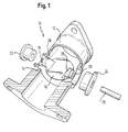
- Fig. 1 shows that in a perspective exploded view Exhaust gas recirculation valve 10 according to the invention, which in one Section 12 of an exhaust gas recirculation line is arranged, the to an intake pipe (not shown) of an engine leads.
- the valve seat 14 that defines the sealing line, formed by a paragraph.
- the valve element 16 (shown open in FIG. 1) lies in the closed state on the valve seat 14 such that the exhaust gas recirculation line is completely closed.
- the Valve element 16 comes out of the open state shown in the closed state as follows.
- Valve element extend at a point in the closed state of the valve element 16 in the shown Example is downstream (the flow of the exhaust gas can 1 from left to right done) on both sides bearing sections 18, 20 with cooperate respective bearing elements 22, 24.
- the Bearing elements 22, 24 are in suitable recesses in the Exhaust gas recirculation line used, and the bearing sections 18, 20 extend into the bearing elements 22, 24 such that the valve element 16 by a cross to the flow direction extending axis is foldable or rotatable.
- the actuation takes place in the case shown by a rotary shaft 26 which with an electrical (not shown) Actuator is connected.
- Valve element 16 which on its circumferential edge is running continuously, in the open state a little below its axis of rotation.
- This connection is at the embodiment shown by itself from that Valve element extending approaches 28 in which the Bearing sections 18, 20 are provided.
- This design essentially causes that by the inventive Exhaust gas recirculation valve the storage and the sealing effect of the Valve element 16 advantageously separated from each other can be. Because of the eccentric, so to speak Attachment of the valve element 16 with respect to its axis of rotation the valve element 16 in the example shown at Overall, closing a little against the direction of flow moves and thus comes fully to the plant Valve seat 14.
- valve element 16 is neither itself nor the valve seat 14 by the rotary bearing of the valve element 16 interrupted, leading to a high susceptibility to leakage would lead.
- the valve element alone is responsible 16 for sealing.
- the sealing line is before storage arranged so that no leakage problems at the storage may occur.
- the valve element 16, which in Fig. 1 can not be seen, with a certain thickness provided, and on its edge it (according to Fig. 1 from Viewer away) tapering, so converging beveled or designed with a spherical edge. As a result, it is reliably due to the comparatively sharp-edged valve seat 14 by an extremely simple machining can be trained.
- the storage of the Valve element 16 (seen in the closed state) not only in the direction of the flow direction of the exhaust gas eccentric, but also in a direction perpendicular to it.
- the storage is according to the illustrated embodiment (seen in the open state) with respect to the extension of the valve element 16 in Flow direction not in the middle, but in this case a little upstream, generally expressed in axial Direction of the exhaust gas recirculation line, offset.
- This is storage within the exhaust gas recirculation line offset above, so that the valve element 16 in open state in the lower area of the Exhaust gas recirculation line is located.
- the Relationships are just the other way round, and that Valve element in an upper area of the Exhaust gas recirculation line is located. This will make one possible little disturbance of the flow of the recirculated exhaust gas reached.
- FIG. 3 shows a preferred construction of the valve element 16 shown.
- This advantageously consists of one Base body 44 on which can also be seen in FIG. 1 Bearing sections 18, 20 are formed.
- On one side of the Base body 44 is used as a receptacle for the actual one Sealing ring 46, which in the closed state of the valve the valve seat 14 rests, essentially a protruding one Ring or a protruding disc 48 is provided.
- the ring or washer 48 a bit have a smaller diameter than the circular one Recess 50 in the sealing ring 46, so that the sealing ring 46 at least slightly in the lateral or radial direction is movable with respect to the base body 44.
- the sealing ring 46 as soon as it comes into contact with the Valve seat 14 comes, can align at least slightly, and possibly compensated for existing tolerances that the sealing ring 46 moves in such a way that he is at all points along its circumference reliably rests on the valve seat 14 and thus minimizes tolerance-related seat leakage.
Abstract
Description
Die Erfindung betrifft ein Abgasrückführventil nach dem Oberbegriff des Anspruchs 1 sowie ein Abgasrückführsystem mit einem derartigen Abgasrückführventil.The invention relates to an exhaust gas recirculation valve according to the Preamble of claim 1 and an exhaust gas recirculation system with such an exhaust gas recirculation valve.
Auf dem Gebiet der Verbrennungsmotoren ist es zur Verringerung von Schadstoffemissionen bekannt, einen Teil des von dem Motor abgegebenen Abgases in die Einlassleitung zurückzuführen. Für die Regelung des zurückgeführten Abgases in Abhängigkeit von dem Betriebszustand des Motors sind Abgasrückführventile erforderlich. Hierbei tritt das Problem auf, dass das Ventil einer Abgasrückführeinrichtung besonderen Anforderungen hinsichtlich der Dichtigkeit unterliegt und wenig anfällig für Leckage sein muss, um eine präzise Abregelung des zurückgeführten Abgasstromes zu ermöglichen. In the field of internal combustion engines it is Known pollutant reduction, part of the Exhaust gas discharged from the engine into the intake pipe due. For the regulation of the recirculated exhaust gas are dependent on the operating state of the engine Exhaust gas recirculation valves required. This is where the problem occurs on that the valve of an exhaust gas recirculation device special tightness requirements is subject to and must be little susceptible to leakage in order to precise regulation of the recirculated exhaust gas flow enable.
Ein Abgasrückführventil nach dem Oberbegriff des Anspruchs 1 ist aus der DE 22 41 935 A1 bekannt. Dieses Abgasrückführventil wird im Wesentlichen wie eine Drosselklappe drehend betätigt. Mit anderen Worten ist in einer Abgasrückführleitung mit weitgehend kreisrundem Querschnitt ein ebenfalls weitgehend kreisrundes Ventilelement vorgesehen, das durch eine Drehachse, an der das Ventilelement angebracht und über die es drehbar gelagert ist, betätigt wird. Hierbei berühren sich die dichtenden Teile, also ein Dichtkegel und die damit zusammenwirkende Dichtkante, lediglich im geschlossenen Zustand. Es tritt idealerweise kein Schleifen oder Reiben zwischen diesen Komponenten beim Öffnungs- und Schließvorgang auf. Im geschlossenen Zustand können somit lediglich diejenigen Abschnitte des Ventilelements, die sich außerhalb der für die Lagerung vorgesehen Drehachse befinden, zur Anlage an einen Ventilsitz gebracht werden.An exhaust gas recirculation valve according to the preamble of claim 1 is known from DE 22 41 935 A1. This Exhaust gas recirculation valve is essentially like one Throttle valve operated by rotation. In other words, is in an exhaust gas recirculation line with largely circular Cross-section also largely circular Valve element provided by an axis of rotation on which the valve element attached and via which it is rotatably mounted is actuated. Here the sealing touch Parts, i.e. a sealing cone and the interacting with it Sealing edge, only when closed. It occurs ideally no grinding or rubbing between them Components during the opening and closing process. in the closed state can only those Sections of the valve element that are outside the for the Storage provided axis of rotation are to be in contact with a Valve seat are brought.
Aus der US 4,222,356 ist ein Abgasrückführsystem bekannt, bei dem ein Klappenventil derart in einem Einlasskanal angeordnet ist, dass es in einem geschlossenen Zustand eine Abgasrückführleitung verschließt, die an der Einlassleitung derart angebracht ist, dass zurückgeführtes Abgas in die Einlassleitung zugeführt wird.An exhaust gas recirculation system is known from US Pat. No. 4,222,356 which a flap valve is arranged in an inlet duct is that in a closed state it is a Exhaust gas recirculation line closes that on the inlet line is attached such that recirculated exhaust gas into the Inlet line is supplied.
Schließlich ist aus der JP 0059034471 ein Abgasrückführventil bekannt, bei dem ein Walzenkörper mit einem Durchgang vorgesehen ist, so dass durch Drehung des Walzenkörpers der Durchgang mit der Abgasrückführleitung verbunden werden kann, und Abgas zurückgeführt wird. Auch in diesem Fall erfolgt die Abdichtung im geschlossenen Zustand jedoch über Elemente, die beweglich sind, so dass eine hohe Gefahr von Leckage besteht. Finally, JP 0059034471 is an exhaust gas recirculation valve known in which a roller body with a passage is provided so that the rotation of the roller body Passage can be connected to the exhaust gas recirculation line, and exhaust gas is recycled. In this case, too Sealing in the closed state, however, via elements that are movable so that there is a high risk of leakage.
Der Erfindung liegt die Aufgabe zugrunde, ein Abgasrückführventil und ein zugehöriges Abgasrückführsystem zu schaffen, mit dem der zurückgeführte Abgasstrom zuverlässig und präzise geregelt werden kann, und das wenig anfällig für Leckage ist.The invention is based on the object Exhaust gas recirculation valve and an associated exhaust gas recirculation system to create with which the recirculated exhaust gas flow can be controlled reliably and precisely, and that little is prone to leakage.
Die Lösung dieser Aufgabe erfolgt durch das im Anspruch 1 beschriebene Abgasrückführventil.This object is achieved by the in claim 1 Exhaust gas recirculation valve described.
Demzufolge weist das erfindungsgemäße Abgasrückführventil, das in einer Abgasrückführleitung und nicht in der Einlassleitung des Motors angeordnet ist, ein Ventilelement auf, das um eine Achse quer zur Strömungsrichtung des Abgases auf einen Ventilsitz klapp-, dreh- oder schwenkbar ist. Erfindungsgemäß ist das Ventilelement jedoch im Gegensatz zu den bekannten Klappen- oder Drehventilen so gestaltet, dass es im geschlossenen Zustand vollständig auf einem Ventilsitz aufliegt. Mit anderen Worten wird der Ventilsitz über seinen gesamten Umfang ausschließlich durch das Ventilelement verschlossen, und es tragen dementsprechend keine Elemente, die bezüglich einander drehbar sind, zur Abdichtung bei. Dies gilt in gleicher Weise für jegliche Elemente, die bezüglich einander verschiebbar oder allgemein relativ beweglich sind, während sie einander berühren, wie dies beispielsweise bei Walzenschiebern der Fall ist. Mit anderen Worten erfolgt die Abdichtung erfindungsgemäß ausschließlich durch das Ventilelement in Zusammenwirkung mit dem Ventilsitz, wobei das Ventilelement im geöffneten Zustand vollständig von dem Ventilsitz gelöst ist, und im geschlossenen Zustand in eine an diesem anliegende Position gebracht wird.Accordingly, the exhaust gas recirculation valve according to the invention has that in an exhaust gas recirculation line and not in the Inlet line of the engine is arranged, a valve element on that about an axis transverse to the flow direction of the exhaust gas can be folded, rotated or swiveled onto a valve seat. According to the invention, however, the valve element is in contrast to the well-known flap or rotary valves designed so that it fully closed on a valve seat rests. In other words, the valve seat is over its entire scope exclusively through the valve element closed, and accordingly there are no elements, which are rotatable with respect to each other, for sealing. This applies in the same way to any elements relating to are mutually displaceable or generally relatively movable, while touching each other, such as in Roller slides is the case. In other words, it does Sealing according to the invention exclusively by Valve element in cooperation with the valve seat, wherein the valve element completely open from the Valve seat is released, and in the closed state in a is brought to this adjacent position.
Dies wird im Wesentlichen dadurch erreicht, dass die Drehlagerung des Ventilelements stromauf- oder stromabwärts von dem Ventilsitz angeordnet ist. Dementsprechend erstreckt sich das Ventilelement im geschlossenen Zustand von der Drehlagerung ein wenig entgegen oder mit der Strömungsrichtung des Abgases, so dass vor oder nach dem Bereich der Drehlagerung durch die Zusammenwirkung zwischen Ventilelement und Ventilsitz eine zuverlässige Abdichtung erreicht wird. Anders als bei den bekannten Dreh- oder Klappventilen sind die Drehwellen, die zur klappbaren Lagerung des Ventilelements vorgesehen sind, nicht an der Abdichtung des Abgasstromes beteiligt, sondern gewährleisten lediglich die klapp-, dreh- oder schwenkbare Beweglichkeit des Ventilelements.This is essentially achieved by the fact that Rotary bearing of the valve element upstream or downstream is arranged by the valve seat. Accordingly extends the valve element in the closed state of the Rotary bearing a little towards or with the Flow direction of the exhaust gas, so that before or after Area of the pivot bearing through the interaction between Valve element and valve seat provide a reliable seal is achieved. Unlike the known rotary or Folding valves are the rotating shafts that are used for folding Storage of the valve element are provided, not on the Sealing the exhaust gas flow involved, but ensure only the foldable, rotatable or swiveling mobility of the valve element.
Das Ventilelement selbst ist dementsprechend so gestaltet, dass es alleine für die Abdichtung an dem Ventilsitz sorgt, und es ist an den Lagerstellen nicht in irgendeiner Weise unterbrochen, was die Gefahr von Leckage mit sich bringen würde. Der Vorteil, dass keinesfalls Elemente, die bezüglich einander beweglich betätigt werden, für die Abdichtung sorgen müssen, besteht auch gegenüber den bekannten Abgasrückführventilen mit Walzenschiebern und gegenüber mittig gelagerten Klappen.The valve element itself is designed accordingly that it alone provides the seal on the valve seat, and it's not at the campsites in any way interrupted, which entails the risk of leakage would. The advantage that there are no elements related to are movably actuated, ensure the sealing must also exist against the known Exhaust gas recirculation valves with roller valves and opposite flaps in the middle.
Vorteilhafte Weiterbildungen des erfindungsgemäßen Abgasrückführventils sind in den weiteren Ansprüchen beschrieben.Advantageous further developments of the invention Exhaust gas recirculation valve are in the further claims described.
Wenngleich die erfindungsgemäßen Vorteile bei einer beliebigen Anordnung der Drehlagerung stromauf- oder stromabwärts des Ventilsitzes erreicht werden können, wird im Rahmen der Erfindung bevorzugt, dass die Lagerung des Ventilelements stromabwärts des Ventilsitzes angeordnet ist. Dies bietet bei dem erfindungsgemäßen Abgasrückführventil den Vorteil, dass sich die Lagerung in einem Bereich befindet, der nicht ständig mit Abgas gefüllt ist, so dass die Lagerung weniger umfangreich verschmutzt wird. Although the advantages of the invention in a any arrangement of the pivot bearing upstream or can be reached downstream of the valve seat is in Within the scope of the invention, the storage of the Valve element is arranged downstream of the valve seat. This offers the in the exhaust gas recirculation valve according to the invention Advantage that the storage is in one area, which is not constantly filled with exhaust gas, so the storage is polluted less extensively.
Wenngleich die Form des Ventilelements und damit die Querschnittsform der Abgasrückführleitung weitgehend beliebig gestaltet werden kann, wird für das Ventilelement ein weitgehend kreisförmiges Element bevorzugt, das mit einem Ventilsitz zusammenwirkt, der in einer Abgasrückführleitung vorgesehen ist, die weitgehend kreisförmig ist.Although the shape of the valve element and thus the Cross-sectional shape of the exhaust gas recirculation line largely arbitrary can be designed for the valve element largely circular element preferred with a Valve seat interacts in an exhaust gas recirculation line is provided, which is largely circular.
Für die Zusammenwirkung zwischen dem Ventilelement und dem Ventilsitz hat es sich als vorteilhaft erwiesen, wenn das Ventilelement mit einer gewissen Dicke ausgebildet ist und an seinem Rand entlang der Dicke abgeschrägt oder sphärisch gestaltet ist. Hierdurch kann das Dichtelement zum einen besonders zuverlässig mit einem weitgehend scharfkantigen Dichtsitz zusammenwirken, an den sich die schräge oder kugelige Randfläche des Dichtelements zuverlässig anlegt. Ferner wird durch eine derartige Gestaltung des Dichtelements die in jedem Motorbetriebspunkt notwendige Durchflussmenge an Abgas zur Verfügung gestellt und kann durch eine entsprechende Stellung des Ventilelements eingestellt werden. Schließlich wird die Strömung des zurückgeführten Abgases im geöffneten Zustand des Abgasrückführventils möglichst wenig beeinträchtigt. Ferner sei erwähnt, dass durch die Abschrägung oder Abrundung des Ventilelements in Kombination mit einer nachfolgend beschriebenen exzentrischen Lagerung des Ventilelements der Vorteil erhalten werden kann, dass das Ventilelement zum Öffnungszeitpunkt an sämtlichen Stellen entlang seines Umfangs gleichzeitig öffnet. Mit anderen Worten wird das Ventilelement zu Beginn des Öffnungsvorgangs entlang seiner Schräge oder Abrundung derart von dem Ventilsitz weggedreht, dass es zunächst noch an sämtlichen Stellen entlang seines Umfangs an diesen anliegt. Zu einem bestimmten Zeitpunkt löst sich dann das gesamte Ventilelement von dem Ventilsitz.For the interaction between the valve element and the Valve seat has proven to be beneficial if that Valve element is formed with a certain thickness and on its edge beveled or spherical along the thickness is designed. As a result, the sealing element on the one hand particularly reliable with a largely sharp-edged Seal seat cooperate to which the oblique or spherical edge surface of the sealing element reliably creates. Furthermore, such a design of the sealing element the flow rate required at each engine operating point Exhaust gas provided and can be supplied by a corresponding position of the valve element can be set. Finally, the flow of the recirculated exhaust gas in the Open the exhaust gas recirculation valve as little as possible impaired. It should also be mentioned that the Chamfer or round off the valve element in combination with an eccentric bearing described below the valve element the advantage can be obtained that the Valve element at all points at the time of opening opens along its circumference at the same time. With others Words the valve element at the beginning of the opening process along its slope or rounding off such from that Valve seat turned away so that it was initially on all Places along its circumference. To a At a certain point in time, the entire valve element is released from the valve seat.
Für die Dichtigkeit des Ventilelements bei dem erfindungsgemäßen Abgasrückführventil bietet es erhebliche Vorteile, wenn das Ventilelement zumindest zweiteilig ausgebildet ist. Hierbei ist ein Teil des Ventilelements, das im geschlossenen Zustand auf dem Ventilsitz aufliegt, gegenüber dem Rest des Ventilelements zumindest geringfügig beweglich vorgesehen. Hierdurch kann dieses Teil, das beispielsweise als beweglicher Dichtring gestaltet sein kann, hinsichtlich seiner Lage bezüglich des Ventilsitzes zumindest geringfügig ausgeglichen werden, so dass es stets dichtend auf dem Ventilsitz aufliegt, und auch Toleranzen ausgeglichen werden können. In dieser Weise sind mit vergleichsweise geringem Aufwand deutlich reduzierte Leckagewerte realisierbar.For the tightness of the valve element in the Exhaust gas recirculation valve according to the invention, it offers considerable Advantages if the valve element consists of at least two parts is trained. Here is part of the valve element that rests on the valve seat when closed, at least slightly compared to the rest of the valve element movably provided. This allows this part, the can be designed, for example, as a movable sealing ring, at least with regard to its position with respect to the valve seat be slightly balanced so that it is always sealing rests on the valve seat, and tolerances are also compensated can be. In this way, are comparatively low effort significantly reduced leakage values realizable.
In diesem Fall wird bevorzugt, dass das bewegliche Teil des Ventilelements durch ein Federelement gehalten wird, so dass es zum einen in einer Richtung gegen ein Lösen gesichert ist und zum anderen in denjenigen Richtungen, in denen Ausgleichsbewegungen erfolgen sollen, beweglich ist.In this case, it is preferred that the movable part of the Valve element is held by a spring element, so that it is secured against loosening in one direction and on the other hand in those directions in which Compensatory movements should take place, is movable.
Für die Drehlagerung des Ventilelements wird bevorzugt, dass diese in einer Richtung quer zur Drehachse bezüglich des Ventilelements exzentrisch vorgesehen ist. Mit anderen Worten ist die Drehlagerung unter der Annahme, dass das Klappen des Ventilelements um eine horizontale Achse erfolgt, ein wenig nach oben oder unten verschoben. Das bedeutet, dass das Ventilelement sich im geöffneten Zustand nicht in der Mitte der Abgasrückführleitung befindet, sondern am oberen oder unteren Rand derselben. Hierdurch wird die Beeinflussung der Strömung des zurückgeführten Abgases weiter vermindert.For the rotary bearing of the valve element, it is preferred that this in a direction transverse to the axis of rotation with respect to the Valve element is provided eccentrically. In other words is the pivot bearing under the assumption that the folding of the Valve element is done around a horizontal axis, a little moved up or down. That means that Valve element is not in the middle when open the exhaust gas recirculation line, but at the top or bottom of the same. This will influence the Flow of the recirculated exhaust gas is further reduced.
In diesem Fall lassen sich besondere Vorteile dadurch erhalten, dass die Lagerung des Ventilelements stromaufwärts des Ventilelements vorgesehen ist. Durch die gewissermaßen doppelt vorhandene Exzentrizität, zum einen die Versetzung der Lagerung des Ventilelements in diesem Fall in stromaufwärtiger Richtung, und zum anderen die Exzentrizität der Lagerung bezüglich der Mittenachse der Abgasrückführleitung, lässt sich die Tatsache, dass auf der einen Seite der Lagerung eine größere Fläche mit Abgasdruck beaufschlagt wird als auf der anderen Seite, dazu nutzen, dass das Schließen des Ventilelements durch den Abgasdruck unterstützt wird, und somit eine Fail-Safe-Funktion realisiert wird.In this case, there are special advantages get that storage of the valve element upstream of the valve element is provided. By the way double eccentricity, on the one hand the dislocation the storage of the valve element in this case upstream direction, and secondly the eccentricity the bearing with respect to the central axis of the Exhaust gas recirculation line, the fact that on the one side of the bearing a larger area with exhaust pressure is acted upon as on the other hand, to use that the closing of the valve element by the exhaust gas pressure is supported, and thus a fail-safe function is realized.
Dies wird ferner durch das ebenfalls bevorzugte Merkmal unterstützt, wonach die Lagerung des Ventilelements an beiden Seiten getrennt voneinander vorgesehen ist. Mit anderen Worten erstreckt sich an dem Ventilelement keine durchgehende Drehwelle von der einen zu der anderen Seite der Abgasrückführleitung. Vielmehr ist das Ventilelement in geeigneter Weise an beiden Seiten getrennt gelagert. Dadurch, dass diese Lagerung getrennt ist, bzw. die Drehwelle geteilt ist, wird die Abgasströmung in äußerst geringem Umfang gestört.This is further enhanced by the also preferred feature supports, after which the storage of the valve element on both Pages are provided separately. With others Words no continuous extends on the valve element Rotary shaft from one side to the other Exhaust gas recirculation line. Rather, the valve element is in suitably stored separately on both sides. Thereby, that this bearing is separate, or the rotating shaft is divided is, the exhaust gas flow is extremely small disturbed.
Für den Betrieb eines Antriebs des erfindungsgemäßen Abgasrückführventils bietet es Vorteile, wenn der Antrieb von dem Ventilelement zumindest weitgehend thermisch entkoppelt ist. Mit anderen Worten sind bevorzugt Maßnahmen dafür vorgesehen, dass eine Wärmeleitung von dem Ventilelement zu dem Antrieb zumindest umfangreich behindert und somit reduziert wird, so dass sich der Antrieb nicht übermäßig erwärmen kann.For the operation of a drive of the invention Exhaust gas recirculation valve offers advantages when driving from the valve element is at least largely thermally decoupled is. In other words, measures for this are preferred provided that heat conduction from the valve element to the drive at least extensively hampered and thus is reduced so that the drive is not excessive can heat.
Dem gleichen Zweck dient die weitere bevorzugte Maßnahme, wonach zwischen dem Antrieb des erfindungsgemäßen Abgasrückführventils und der Abgasrückführleitung, in dem das Ventil angeordnet ist, zumindest ein Abschirmblech vorgesehen ist. Auch dieses verhindert Wärmeleitung und -strahlung, die den Antrieb in unerwünschter Weise erwärmen würde.The further preferred measure serves the same purpose, after which between the drive of the invention Exhaust gas recirculation valve and the exhaust gas recirculation line, in which the Valve is arranged, at least one shield plate is provided is. This also prevents heat conduction and radiation would undesirably heat the drive.
Schließlich kann eine Erwärmung des Antriebs zusätzlich dadurch verhindert werden, dass, wie bevorzugt vorgesehen ist, der Antrieb lediglich an diskreten Stellen mit der Abgasrückführleitung verbunden ist. Finally, heating of the drive can additionally thereby being prevented as intended is, the drive only at discrete points with the Exhaust gas recirculation line is connected.
Die Lösung der oben genannten Aufgabe erfolgt erfindungsgemäß ferner durch das im Anspruch 13 beschriebene Abgasrückführsystem, das zumindest ein Abgasrückführventil gemäß der Erfindung aufweist. Hierdurch können die erfindungsgemäßen Vorteile für ein Abgasrückführsystem insgesamt erhalten werden, wobei das Abgasrückführventil nicht notwendigerweise als getrenntes Bauteil vorgesehen sein muss, sondern beispielsweise durch eine geeignete Anordnung eines Ventilelements und dessen Lagerung in einem Abschnitt einer Abgasrückführleitung gebildet werden kann.The above object is achieved according to the invention further by that described in claim 13 Exhaust gas recirculation system, the at least one exhaust gas recirculation valve according to the invention. This allows the Advantages according to the invention for an exhaust gas recirculation system can be obtained overall, with the exhaust gas recirculation valve not necessarily be provided as a separate component must, but for example by a suitable arrangement a valve element and its storage in one section an exhaust gas recirculation line can be formed.
Nachfolgend wird die Erfindung rein beispielhaft anhand von in den Zeichnungen dargestellten Ausführungsformen näher erläutert. Es zeigen:
- Fig. 1
- eine Explosionsdarstellung des erfindungsgemäßen Abgasrückführventils;
- Fig. 2
- eine Explosionsansicht des erfindungsgemäßen Abgasrückführventils mit elektrischem Antrieb in einer zweiten Ausführungsform; und
- Fig. 3
- eine Explosionsansicht einer Ausführungsform des Ventilelements mit reduzierter Ventilleckage für das erfindungsgemäße Abgasrückführventil.
- Fig. 1
- an exploded view of the exhaust gas recirculation valve according to the invention;
- Fig. 2
- an exploded view of the exhaust gas recirculation valve according to the invention with an electric drive in a second embodiment; and
- Fig. 3
- an exploded view of an embodiment of the valve element with reduced valve leakage for the exhaust gas recirculation valve according to the invention.
Fig. 1 zeigt in einer perspektivischen Explosionsansicht das
erfindungsgemäße Abgasrückführventil 10, das in einem
Abschnitt 12 einer Abgasrückführleitung angeordnet ist, der
zu einer (nicht dargestellten) Einlassleitung eines Motors
führt. Wie in Fig. 1 zu erkennen ist, wird der Ventilsitz 14,
der die Dichtlinie definiert, durch einen Absatz gebildet.
Das (in Fig. 1 offen dargestellte) Ventilelement 16 liegt im
geschlossenen Zustand derart an dem Ventilsitz 14 an, dass
die Abgasrückführleitung vollständig verschlossen wird. Das
Ventilelement 16 gelangt aus dem gezeigten, offenen Zustand
folgendermaßen in den geschlossenen Zustand. Von dem
Ventilelement erstrecken sich an einer Stelle, die im
geschlossenen Zustand des Ventilelements 16 bei dem gezeigten
Beispiel stromabwärts liegt (die Strömung des Abgases kann
bei der Darstellung der Fig. 1 von links nach rechts
erfolgen) an beiden Seiten Lagerabschnitte 18, 20, die mit
jeweiligen Lagerelementen 22, 24 zusammenwirken. Die
Lagerelemente 22, 24 sind in geeignete Aussparungen in der
Abgasrückführleitung eingesetzt, und die Lagerabschnitte 18,
20 erstrecken sich derart in die Lagerelemente 22, 24, dass
das Ventilelement 16 um eine quer zur Strömungsrichtung
verlaufende Achse klapp- oder drehbar ist. Die Betätigung
erfolgt in dem gezeigten Fall durch eine Drehwelle 26, die
mit einer (nicht gezeigten) elektrischen
Betätigungseinrichtung verbunden ist.Fig. 1 shows that in a perspective exploded view
Exhaust
Wie in Fig. 1 zu erkennen ist, befindet sich das
Ventilelement 16, das an seinem umlaufenden Rand
ununterbrochen ausgeführt ist, im geöffneten Zustand ein
wenig unterhalb seiner Drehachse. Diese Anbindung wird bei
dem gezeigten Ausführungsbeispiel durch sich von dem
Ventilelement erstreckende Ansätze 28 erreicht, in denen die
Lagerabschnitte 18, 20 vorgesehen sind. Diese Gestaltung
bewirkt im Wesentlichen, dass durch das erfindungsgemäße
Abgasrückführventil die Lagerung und die Dichtwirkung des
Ventilelements 16 in vorteilhafter Weise voneinander getrennt
werden können. Durch die gewissermaßen exzentrische
Anbringung des Ventilelements 16 bezüglich seiner Drehachse
wird das Ventilelement 16 bei dem gezeigten Beispiel beim
Schließen insgesamt ein wenig entgegen der Strömungsrichtung
bewegt und gelangt somit vollständig zur Anlage an den
Ventilsitz 14. As can be seen in Fig. 1, that is
Mit anderen Worten ist weder das Ventilelement 16 selbst noch
der Ventilsitz 14 durch die Drehlagerung des Ventilelements
16 unterbrochen, was zu einer hohen Anfälligkeit für Leckage
führen würde. Gewissermaßen sorgt alleine das Ventilelement
16 für die Abdichtung. Die Dichtlinie ist vor der Lagerung
angeordnet, so dass an der Lagerung keine Leckageprobleme
auftreten können. Ferner ist das Ventilelement 16, was in
Fig. 1 nicht zu erkennen ist, mit einer gewissen Dicke
versehen, und an seinem Rand ist es (gemäß Fig. 1 vom
Betrachter weg) sich verjüngend, also zusammenlaufend
abgeschrägt oder mit einem sphärischen Rand gestaltet.
Hierdurch liegt es zuverlässig an dem vergleichsweise
scharfkantigen Ventilsitz 14 an, der durch eine äußerst
einfache Bearbeitung ausgebildet werden kann.In other words, the
Wie in Fig. 1 ferner zu erkennen ist, ist die Lagerung des
Ventilelements 16 (im geschlossenen Zustand gesehen) nicht
nur in Richtung der Strömungsrichtung des Abgases
exzentrisch, sondern auch in einer Richtung senkrecht hierzu.
Mit anderen Worten befindet sich die Lagerung gemäß der
dargestellten Ausführungsform (im offenen Zustand gesehen)
bezüglich der Erstreckung des Ventilelements 16 in
Strömungsrichtung nicht in der Mitte, sondern in diesem Fall
ein wenig stromaufwärts, allgemein ausgedrückt in axialer
Richtung der Abgasrückführleitung, versetzt. Hierdurch ist
auch die Lagerung innerhalb der Abgasrückführleitung nach
oben versetzt, so dass das Ventilelement 16 sich im
geöffneten Zustand im unteren Bereich der
Abgasrückführleitung befindet. Ebenso wäre denkbar, dass die
Verhältnisse gerade umgekehrt sind, und sich das
Ventilelement in einem oberen Bereich der
Abgasrückführleitung befindet. Hierdurch wird eine möglichst
geringe Störung der Strömung des zurückgeführten Abgases
erreicht. As can also be seen in Fig. 1, the storage of the
Valve element 16 (seen in the closed state) not
only in the direction of the flow direction of the exhaust gas
eccentric, but also in a direction perpendicular to it.
In other words, the storage is according to the
illustrated embodiment (seen in the open state)
with respect to the extension of the
Dies wird ferner unterstützt dadurch, dass die Lagerung
beider Seiten getrennt ausgeführt ist. Mit anderen Worten
erstreckt sich zwischen den beiden Ansätzen 28 keine
durchgehende Lagerwelle, sondern die beiden Lagerabschnitte
18, 20 sind getrennt voneinander vorgesehen. Dadurch, dass
ein sich quer durch die Abgasrückführleitung erstreckendes
Element vermieden wird, wird die Strömung des zurückgeführten
Abgases in geringstmöglichem Umfang beeinträchtigt.This is further supported by the fact that storage
is carried out separately on both sides. In other words
none extends between the two approaches 28
continuous bearing shaft, but the two bearing
Die in Fig. 2 gezeigte Ausführungsform des erfindungsgemäßen
Abgasrückführventils 10 ist gegenüber der in Fig. 1 gezeigten
Ausführungsform um einen Antrieb 30 und verschiedene
Maßnahmen zur thermischen Entkopplung des Antriebs 30 von dem
Ventilelement 16 ergänzt. Bei dem gezeigten
Ausführungsbeispiel handelt es sich bei dem Antrieb 30 um
einen elektrischen Antrieb. Dieser kann jedoch auch in
anderer Weise, beispielsweise als hydraulischer,
pneumatischer oder mechanischer Antrieb ausgeführt sein. In
grundsätzlich mit der Ausführungsform von Fig. 1
übereinstimmender Art und Weise ist das Ventilelement 16 an
den beiden Seiten getrennt gelagert, wobei sich die Lagerung
auch bei dieser Ausführungsform ein wenig stromabwärts,
allgemein ausgedrückt in axialer Richtung der
Abgasrückführleitung, bezüglich des Ventilsitzes 14 befindet.
Der Antrieb des Ventilelements 16 erfolgt durch die auch bei
der Ausführungsform von Fig. 1 vorhandene Drehwelle 26, die
bei der Ausführungsform von Fig. 2 jedoch an ihrem äußeren
Ende mit einem Vierkant 32 versehen ist. Selbstverständlich
können andere Maßnahmen als die gezeigte Vierkantkontur
vorgesehen sein, um eine Übertragung eines Drehmoments auf
das Ventilelement 16 durch den Antrieb 30 zu ermöglichen. Bei
der in Fig. 2 gezeigten Ausführungsform erfolgt diese
Übertragung durch eine zwischen der Drehwelle 26 und einer
Ausgangswelle des Antriebs 30 vorgesehene, im weitesten Sinne
U-förmige Klammer 34, die in ihren beiden Schenkeln jeweils
eine rechteckige oder quadratische Ausnehmung 36 aufweist,
die mit der Drehwelle 26 bzw. der Ausgangswelle des Motors
derart in Eingriff ist, dass eine Drehbewegung übertragen
werden kann. Dadurch, dass die Drehwelle 26 über ein
gesondertes Übertragungselement, insbesondere die
vergleichsweise dünnwandige Klammer 34 mit dem Antrieb
verbunden ist, kann an dieser Stelle nur in äußerst geringem
Umfang Wärme von dem sich infolge des Abgasstromes
erwärmenden Ventilelement 16 zu dem Antrieb 30 übertragen
werden, und eine unerwünschte Erwärmung des Antriebs 30 kann
in vorteilhafter Weise vermieden werden.The embodiment of the invention shown in Fig. 2
Exhaust
Dies wird bei der Ausführungsform von Fig. 2 unterstützt
durch ein Abschirmblech 38, das weitgehend L-förmig gestaltet
sein kann und den Antrieb 30 von der Abgasrückführleitung 12
gegen Wärmestrahlung abschirmt, in dem sich das
Abgasrückführventil befindet, das durch den Antrieb 30
anzutreiben ist. Insbesondere erstreckt sich ein in Fig. 2
weitgehend horizontal ausgerichteter Schenkel des
Abschirmblechs 38 derart parallel zu dem zylinderförmigen
Motorabschnitt des Antriebs 30, dass hier keine unerwünschte
Wärmeleitung oder Strahlung auf den Motor einwirken kann. Der
sich weitgehend vertikal erstreckende Abschnitt des
Abschirmblechs 38 schirmt eine daran angrenzende
Getriebeeinheit des Antriebs 30 von der warmen
Abgasrückführleitung ab.This is supported in the embodiment of FIG. 2
by a shielding
Schließlich erfolgt eine vorteilhafte thermische Entkopplung
des Antriebs 30 dadurch, dass dieser lediglich an diskreten
Stellen mit der Abgasrückführleitung verbunden ist. Dies
erfolgt bei der gezeigten Ausführungsform durch einen
geeigneten Fuß 40. Durch diese Anbindung sowie durch die in
dem Abschirmblech 38 zu erkennenden Öffnungen kann der
Antrieb 30 mittels geeigneter Verbindungselemente an Ansätzen
42 an der Abgasrückführleitung befestigt werden. Es sei
angemerkt, dass ähnliche Befestigungsansätze 42 und ein
entsprechender Fuß 40 auch an dem sich weitgehend vertikal
erstreckenden Getriebeabschnitt des Antriebs 30 vorgesehen
sein können, um auch in einem um 90° seitlich versetzten
Bereich eine Befestigung des Antriebs 30 an wenigen diskreten
Stellen zu gewährleisten. Zur weiteren Reduzierung der
Wärmeübertragung auf den Antrieb 30 können an den
Befestigungspunkten Isolationselemente, beispielsweise aus
Glimmer, oder keramische Isolationselemente, eingesetzt
werden. Hierdurch wird in jedem Fall der Umfang der
Wärmeübertragung auf den Antrieb 30 in vorteilhafter Weise
reduziert.Finally, there is an advantageous thermal decoupling
of the
In Fig. 3 ist ein bevorzugter Aufbau des Ventilelements 16
dargestellt. Dieses besteht in vorteilhafter Weise aus einem
Grundkörper 44, an dem die auch in Fig. 1 zu erkennenden
Lagerabschnitte 18, 20 ausgebildet sind. An einer Seite des
Grundkörpers 44 ist als Aufnahme für den eigentlichen
Dichtring 46, der im geschlossenen Zustand des Ventils auf
dem Ventilsitz 14 aufliegt, im Wesentlichen ein vorstehender
Ring oder eine vorstehende Scheibe 48 vorgesehen. Es sei
angemerkt, dass der Ring oder die Scheibe 48 einen etwas
geringeren Durchmesser aufweisen als die kreisförmige
Ausnehmung 50 in dem Dichtring 46, so dass der Dichtring 46
zumindest geringfügig in seitlicher oder radialer Richtung
bezüglich des Grundkörpers 44 beweglich ist. Dies bedeutet,
dass sich der Dichtring 46, sobald er zur Anlage an dem
Ventilsitz 14 kommt, zumindest geringfügig ausrichten kann,
und möglicherweise vorhandene Toleranzen derart ausgeglichen
werden können, dass sich der Dichtring 46 derart verschiebt,
dass er an sämtlichen Stellen entlang seines Umfangs
zuverlässig dichtend auf dem Ventilsitz 14 aufliegt und somit
eine toleranzbedingte Sitzleckage minimiert.3 shows a preferred construction of the
Gegen ein Lösen des Dichtrings 46 von dem Grundkörper 44 ist
ein sternförmiges Federelement 52 vorgesehen. Dieses
sternförmige Federelement 52, das selbstverständlich auch
unterschiedlich gestaltet sein kann, ist mit seiner inneren
kreisförmigen Ausnehmung 54 fest auf einen weiteren ringoder
scheibenförmigen Vorsprung 56 gefügt, der an dem ringoder
scheibenförmigen Vorsprung 48 des Grundkörpers 44
vorgesehen ist. In dieser Weise wird der Dichtring 46 derart
an dem Grundkörper 44 gehalten, dass er sich in radialen
Richtungen bewegen kann, um Toleranzen auszugleichen, jedoch
sich in axialer Richtung nicht von diesem lösen kann.Against a loosening of the sealing ring 46 from the base body 44
a star-shaped
Claims (13)
dadurch gekennzeichnet, dass
der Ventilsitz (14) im geschlossenen Zustand um seinen gesamten Umfang von dem Ventilelement (16) verschlossen wird.Exhaust gas recirculation valve (10) which is arranged in an exhaust gas recirculation line (12) and has a valve element (16) which can be folded, rotated or pivoted onto a valve seat (14) about an axis transverse to the direction of flow onto a valve seat (14),
characterized in that
the valve seat (14) is closed around its entire circumference by the valve element (16).
dadurch gekennzeichnet, dass
die Lagerung (18, 20, 22, 24) des Ventilelements (16) stromabwärts des Ventilsitzes (14) angeordnet ist.Exhaust gas recirculation valve according to claim 1,
characterized in that
the bearing (18, 20, 22, 24) of the valve element (16) is arranged downstream of the valve seat (14).
dadurch gekennzeichnet, dass
das Ventilelement (16) weitgehend kreisförmig ausgebildet ist.Exhaust gas recirculation valve according to claim 1 or 2,
characterized in that
the valve element (16) is largely circular.
dadurch gekennzeichnet, dass
das Ventilelement (16) an seinem Rand entlang seiner Dicke abgeschrägt oder sphärisch gestaltet ist.Exhaust gas recirculation valve according to at least one of the preceding claims,
characterized in that
the valve element (16) is chamfered at its edge along its thickness or is spherical.
dadurch gekennzeichnet, dass
das Ventilelement (16) zumindest zweiteilig ausgebildet ist, wobei ein auf dem Ventilsitz (14) im geschlossenen Zustand aufliegendes Teil (46) zumindest geringfügig beweglich vorgesehen ist. Exhaust gas recirculation valve according to at least one of the preceding claims,
characterized in that
the valve element (16) is formed at least in two parts, a part (46) resting on the valve seat (14) in the closed state being at least slightly movable.
dadurch gekennzeichnet, dass
das bewegliche Teil (46) durch ein Federelement (52) gehalten wird.Exhaust gas recirculation valve according to claim 5,
characterized in that
the movable part (46) is held by a spring element (52).
dadurch gekennzeichnet, dass
die Lagerung (18, 20, 22, 24) in einer Richtung quer zur Drehachse exzentrisch bezüglich des Ventilelements (16) vorgesehen ist.Exhaust gas recirculation valve according to at least one of the preceding claims,
characterized in that
the bearing (18, 20, 22, 24) is provided eccentrically in a direction transverse to the axis of rotation with respect to the valve element (16).
dadurch gekennzeichnet, dass
die Lagerung (18, 20, 22, 24) des Ventilelements (16) stromaufwärts des Ventilsitzes (14) angeordnet ist.Exhaust gas recirculation valve according to claim 7,
characterized in that
the bearing (18, 20, 22, 24) of the valve element (16) is arranged upstream of the valve seat (14).
dadurch gekennzeichnet, dass
die Lagerung (18, 20, 22, 24) des Ventilelements (16) an beiden Seiten getrennt voneinander vorgesehen ist.Exhaust gas recirculation valve according to at least one of the preceding claims,
characterized in that
the bearing (18, 20, 22, 24) of the valve element (16) is provided separately on both sides.
dadurch gekennzeichnet, dass
dieses einen insbesondere elektrischen Antrieb (30) aufweist, der von dem Ventilelement (16) zumindest weitgehend thermisch entkoppelt ist.Exhaust gas recirculation valve according to at least one of the preceding claims,
characterized in that
the latter has, in particular, an electrical drive (30) which is at least largely thermally decoupled from the valve element (16).
dadurch gekennzeichnet, dass
zwischen dem Antrieb (30) und der Abgasrückführleitung (12) zumindest ein Abschirmblech (38) vorgesehen ist. Exhaust gas recirculation valve according to claim 10,
characterized in that
at least one shield plate (38) is provided between the drive (30) and the exhaust gas recirculation line (12).
dadurch gekennzeichnet, dass
der Antrieb (30) lediglich an diskreten Stellen mit der Abgasrückführleitung (12) verbunden ist.Exhaust gas recirculation valve according to claim 10 or 11,
characterized in that
the drive (30) is connected to the exhaust gas recirculation line (12) only at discrete points.
Priority Applications (5)
| Application Number | Priority Date | Filing Date | Title |
|---|---|---|---|
| AT01107497T ATE317062T1 (en) | 2001-03-29 | 2001-03-29 | EXHAUST GAS RECIRCULATION VALVE |
| EP01107497A EP1245820B1 (en) | 2001-03-29 | 2001-03-29 | Exhaust gas recirculation valve |
| PT01107497T PT1245820E (en) | 2001-03-29 | 2001-03-29 | RECIRCULATION VALVE OF EXHAUST GASES |
| DE50108825T DE50108825D1 (en) | 2001-03-29 | 2001-03-29 | Exhaust gas recirculation valve |
| ES01107497T ES2260110T3 (en) | 2001-03-29 | 2001-03-29 | EXHAUST GAS RECIRCULATION VALVE. |
Applications Claiming Priority (1)
| Application Number | Priority Date | Filing Date | Title |
|---|---|---|---|
| EP01107497A EP1245820B1 (en) | 2001-03-29 | 2001-03-29 | Exhaust gas recirculation valve |
Publications (2)
| Publication Number | Publication Date |
|---|---|
| EP1245820A1 true EP1245820A1 (en) | 2002-10-02 |
| EP1245820B1 EP1245820B1 (en) | 2006-02-01 |
Family
ID=8176939
Family Applications (1)
| Application Number | Title | Priority Date | Filing Date |
|---|---|---|---|
| EP01107497A Expired - Lifetime EP1245820B1 (en) | 2001-03-29 | 2001-03-29 | Exhaust gas recirculation valve |
Country Status (5)
| Country | Link |
|---|---|
| EP (1) | EP1245820B1 (en) |
| AT (1) | ATE317062T1 (en) |
| DE (1) | DE50108825D1 (en) |
| ES (1) | ES2260110T3 (en) |
| PT (1) | PT1245820E (en) |
Cited By (9)
| Publication number | Priority date | Publication date | Assignee | Title |
|---|---|---|---|---|
| EP1544449A1 (en) | 2003-12-19 | 2005-06-22 | Cooper-Standard Automotive (Deutschland) GmbH | Exhaust gas recirculation valve |
| EP1657424A2 (en) | 2004-11-10 | 2006-05-17 | Pierburg GmbH | Exhaust gas recirculation system for an internal combustion engine |
| DE102004040817B4 (en) * | 2004-08-24 | 2008-12-04 | Pierburg Gmbh | Exhaust flap means |
| US7533659B2 (en) | 2006-07-06 | 2009-05-19 | Cooper-Standard Automotive (Deutchland) Gmbh | Exhaust-gas recirculation valve |
| EP2180167A1 (en) | 2008-10-23 | 2010-04-28 | Küster Holding GmbH | Exhaust gas valve drive for a motor vehicle |
| US8353274B2 (en) | 2007-07-30 | 2013-01-15 | Cooper-Standard Automotive (Deutschland) Gmbh | Exhaust gas recirculation system |
| DE102018214069A1 (en) * | 2018-08-21 | 2020-02-27 | Continental Automotive Gmbh | Valve for controlling exhaust gas or fresh air in a drive unit of a motor vehicle or generator |
| CN113494395A (en) * | 2020-04-01 | 2021-10-12 | 尤姆弗泰克有限公司 | Control flap for targeted exhaust gas recirculation and method for producing the same |
| DE102009016597C5 (en) | 2009-04-08 | 2023-03-23 | Küster Holding GmbH | Exhaust flap drive for a motor vehicle |
Citations (9)
| Publication number | Priority date | Publication date | Assignee | Title |
|---|---|---|---|---|
| DE2241935A1 (en) | 1972-08-25 | 1974-03-07 | Bosch Gmbh Robert | SYSTEM FOR EXHAUST GAS DETOXIFICATION |
| US4171689A (en) * | 1977-01-29 | 1979-10-23 | Robert Bosch Gmbh | Device for the control of gas admissions into the induction manifold of an internal combustion engine |
| US4222356A (en) | 1978-09-13 | 1980-09-16 | Toyota Jidosha Kogyo Kabushiki Kaisha | Exhaust gas recirculation for a diesel engine |
| DE2918348A1 (en) * | 1979-05-07 | 1980-11-20 | Adams Gmbh & Co Kg Armaturen & | Butterfly valve with double seat - has sliding disc actuated by rod in spindle via bell-crank lever |
| JPS5934471A (en) | 1982-08-20 | 1984-02-24 | Yanmar Diesel Engine Co Ltd | Exhaust gas recirculation system for internal combustion engine |
| US5148678A (en) * | 1989-12-26 | 1992-09-22 | Aisan Kogyo Kabushiki Kaisha | Exhaust gas flow control valve for internal combustion engine |
| US5531205A (en) * | 1995-03-31 | 1996-07-02 | Siemens Electric Limited | Rotary diesel electric EGR valve |
| EP0887541A2 (en) * | 1997-06-25 | 1998-12-30 | Lucas Industries Public Limited Company | Exhast gas recirculation valve |
| EP1020633A1 (en) * | 1998-07-07 | 2000-07-19 | Man Nutzfahrzeuge Ag | One way valve for exhaust gas recirculation |
-
2001
- 2001-03-29 AT AT01107497T patent/ATE317062T1/en active
- 2001-03-29 ES ES01107497T patent/ES2260110T3/en not_active Expired - Lifetime
- 2001-03-29 EP EP01107497A patent/EP1245820B1/en not_active Expired - Lifetime
- 2001-03-29 PT PT01107497T patent/PT1245820E/en unknown
- 2001-03-29 DE DE50108825T patent/DE50108825D1/en not_active Expired - Lifetime
Patent Citations (9)
| Publication number | Priority date | Publication date | Assignee | Title |
|---|---|---|---|---|
| DE2241935A1 (en) | 1972-08-25 | 1974-03-07 | Bosch Gmbh Robert | SYSTEM FOR EXHAUST GAS DETOXIFICATION |
| US4171689A (en) * | 1977-01-29 | 1979-10-23 | Robert Bosch Gmbh | Device for the control of gas admissions into the induction manifold of an internal combustion engine |
| US4222356A (en) | 1978-09-13 | 1980-09-16 | Toyota Jidosha Kogyo Kabushiki Kaisha | Exhaust gas recirculation for a diesel engine |
| DE2918348A1 (en) * | 1979-05-07 | 1980-11-20 | Adams Gmbh & Co Kg Armaturen & | Butterfly valve with double seat - has sliding disc actuated by rod in spindle via bell-crank lever |
| JPS5934471A (en) | 1982-08-20 | 1984-02-24 | Yanmar Diesel Engine Co Ltd | Exhaust gas recirculation system for internal combustion engine |
| US5148678A (en) * | 1989-12-26 | 1992-09-22 | Aisan Kogyo Kabushiki Kaisha | Exhaust gas flow control valve for internal combustion engine |
| US5531205A (en) * | 1995-03-31 | 1996-07-02 | Siemens Electric Limited | Rotary diesel electric EGR valve |
| EP0887541A2 (en) * | 1997-06-25 | 1998-12-30 | Lucas Industries Public Limited Company | Exhast gas recirculation valve |
| EP1020633A1 (en) * | 1998-07-07 | 2000-07-19 | Man Nutzfahrzeuge Ag | One way valve for exhaust gas recirculation |
Cited By (13)
| Publication number | Priority date | Publication date | Assignee | Title |
|---|---|---|---|---|
| US7182315B2 (en) | 2003-12-19 | 2007-02-27 | Cooper-Standard Automotive (Deutschland) Gmbh | Exhaust-gas recirculation valve |
| CN100430593C (en) * | 2003-12-19 | 2008-11-05 | 库帕-标准汽车(德国)有限责任公司 | Exhaust gas recirculation valve |
| EP1544449A1 (en) | 2003-12-19 | 2005-06-22 | Cooper-Standard Automotive (Deutschland) GmbH | Exhaust gas recirculation valve |
| DE102004040817B4 (en) * | 2004-08-24 | 2008-12-04 | Pierburg Gmbh | Exhaust flap means |
| EP1657424A2 (en) | 2004-11-10 | 2006-05-17 | Pierburg GmbH | Exhaust gas recirculation system for an internal combustion engine |
| EP1657424A3 (en) * | 2004-11-10 | 2010-09-08 | Pierburg GmbH | Exhaust gas recirculation system for an internal combustion engine |
| US7533659B2 (en) | 2006-07-06 | 2009-05-19 | Cooper-Standard Automotive (Deutchland) Gmbh | Exhaust-gas recirculation valve |
| US8353274B2 (en) | 2007-07-30 | 2013-01-15 | Cooper-Standard Automotive (Deutschland) Gmbh | Exhaust gas recirculation system |
| EP2180167A1 (en) | 2008-10-23 | 2010-04-28 | Küster Holding GmbH | Exhaust gas valve drive for a motor vehicle |
| DE102009016597C5 (en) | 2009-04-08 | 2023-03-23 | Küster Holding GmbH | Exhaust flap drive for a motor vehicle |
| DE102018214069A1 (en) * | 2018-08-21 | 2020-02-27 | Continental Automotive Gmbh | Valve for controlling exhaust gas or fresh air in a drive unit of a motor vehicle or generator |
| CN113494395A (en) * | 2020-04-01 | 2021-10-12 | 尤姆弗泰克有限公司 | Control flap for targeted exhaust gas recirculation and method for producing the same |
| CN113494395B (en) * | 2020-04-01 | 2023-09-01 | 尤姆弗泰克有限公司 | Control flap for the targeted recirculation of exhaust gases and method for the production thereof |
Also Published As
| Publication number | Publication date |
|---|---|
| DE50108825D1 (en) | 2006-04-13 |
| EP1245820B1 (en) | 2006-02-01 |
| ATE317062T1 (en) | 2006-02-15 |
| ES2260110T3 (en) | 2006-11-01 |
| PT1245820E (en) | 2006-06-30 |
Similar Documents
| Publication | Publication Date | Title |
|---|---|---|
| DE69810850T2 (en) | Exhaust gas recirculation valve | |
| DE60009590T2 (en) | Exhaust gas recirculation system and actuator therefor | |
| EP2084439B1 (en) | Rotary slide valve, in particular for a coolant circuit, which has a plurality of branches, of an internal combustion engine; electromechanical assembly | |
| DE102006054041B3 (en) | Regulating device for an internal combustion engine | |
| EP0320490A2 (en) | Cut-off member | |
| EP1347154B1 (en) | Valve lift control for internal combustion engine | |
| WO2014033075A1 (en) | Exhaust-gas heat exchanger | |
| DE2924800C2 (en) | Throttle device for a twin-screw screw machine | |
| EP1493951A2 (en) | Butterfly valve | |
| EP1245820B1 (en) | Exhaust gas recirculation valve | |
| EP0856657A2 (en) | Exhaust gas recirculation valve for a combustion engine | |
| EP3615787B1 (en) | Valve for an internal combustion engine | |
| EP1526271A1 (en) | Exhaust gas recirculation valve | |
| EP1526272B1 (en) | Exhaust gas recirculation valve | |
| DE3842974A1 (en) | DIAPHRAGM CARBURETTOR WITH POSITIONALLY COUPLED THROTTLE VALVE AND CHOKE VALVE | |
| EP0348432B1 (en) | Device for controlling at least one throttle cross-section at at least one control opening | |
| EP2172638B1 (en) | Valve device for controlling an exhaust gas flow | |
| DE10234867A1 (en) | Swing motor for a camshaft adjustment device | |
| EP2478204B1 (en) | Control unit and coupling device | |
| DE3804333C2 (en) | Device for changing the control angle between a machine part and a drive unit actuating it | |
| DE2938372A1 (en) | INTERNAL COMBUSTION ENGINE | |
| EP2837779B1 (en) | Valve control for a gas exchange valve of a combustion engine | |
| EP1340892A2 (en) | Valve for opening and closing of an intake tube | |
| DE4242634A1 (en) | Combustion engine valve control mechanism - has gear and worm drive between engine crankshaft and cam shafts, gear drive having conical wheels and worm drive slidable along own axis | |
| DE3504608A1 (en) | Shut-off element for pipes |
Legal Events
| Date | Code | Title | Description |
|---|---|---|---|
| PUAI | Public reference made under article 153(3) epc to a published international application that has entered the european phase |
Free format text: ORIGINAL CODE: 0009012 |
|
| 17P | Request for examination filed |
Effective date: 20020215 |
|
| AK | Designated contracting states |
Kind code of ref document: A1 Designated state(s): AT BE CH CY DE DK ES FI FR GB GR IE IT LI LU MC NL PT SE TR |
|
| AX | Request for extension of the european patent |
Free format text: AL;LT;LV;MK;RO;SI |
|
| AKX | Designation fees paid |
Designated state(s): AT BE CH CY DE DK ES FI FR GB GR IE IT LI LU MC NL PT SE TR |
|
| 17Q | First examination report despatched |
Effective date: 20040811 |
|
| GRAP | Despatch of communication of intention to grant a patent |
Free format text: ORIGINAL CODE: EPIDOSNIGR1 |
|
| GRAS | Grant fee paid |
Free format text: ORIGINAL CODE: EPIDOSNIGR3 |
|
| GRAA | (expected) grant |
Free format text: ORIGINAL CODE: 0009210 |
|
| AK | Designated contracting states |
Kind code of ref document: B1 Designated state(s): AT BE CH CY DE DK ES FI FR GB GR IE IT LI LU MC NL PT SE TR |
|
| PG25 | Lapsed in a contracting state [announced via postgrant information from national office to epo] |
Ref country code: NL Free format text: LAPSE BECAUSE OF FAILURE TO SUBMIT A TRANSLATION OF THE DESCRIPTION OR TO PAY THE FEE WITHIN THE PRESCRIBED TIME-LIMIT Effective date: 20060201 Ref country code: FI Free format text: LAPSE BECAUSE OF FAILURE TO SUBMIT A TRANSLATION OF THE DESCRIPTION OR TO PAY THE FEE WITHIN THE PRESCRIBED TIME-LIMIT Effective date: 20060201 |
|
| REG | Reference to a national code |
Ref country code: GB Ref legal event code: FG4D Free format text: NOT ENGLISH |
|
| REG | Reference to a national code |
Ref country code: CH Ref legal event code: EP |
|
| REG | Reference to a national code |
Ref country code: IE Ref legal event code: FG4D Free format text: LANGUAGE OF EP DOCUMENT: GERMAN |
|
| PG25 | Lapsed in a contracting state [announced via postgrant information from national office to epo] |
Ref country code: MC Free format text: LAPSE BECAUSE OF NON-PAYMENT OF DUE FEES Effective date: 20060331 Ref country code: CH Free format text: LAPSE BECAUSE OF NON-PAYMENT OF DUE FEES Effective date: 20060331 Ref country code: LI Free format text: LAPSE BECAUSE OF NON-PAYMENT OF DUE FEES Effective date: 20060331 |
|
| REF | Corresponds to: |
Ref document number: 50108825 Country of ref document: DE Date of ref document: 20060413 Kind code of ref document: P |
|
| PG25 | Lapsed in a contracting state [announced via postgrant information from national office to epo] |
Ref country code: DK Free format text: LAPSE BECAUSE OF FAILURE TO SUBMIT A TRANSLATION OF THE DESCRIPTION OR TO PAY THE FEE WITHIN THE PRESCRIBED TIME-LIMIT Effective date: 20060501 |
|
| REG | Reference to a national code |
Ref country code: SE Ref legal event code: TRGR |
|
| GBT | Gb: translation of ep patent filed (gb section 77(6)(a)/1977) |
Effective date: 20060517 |
|
| REG | Reference to a national code |
Ref country code: PT Ref legal event code: SC4A Effective date: 20060428 |
|
| NLV1 | Nl: lapsed or annulled due to failure to fulfill the requirements of art. 29p and 29m of the patents act | ||
| ET | Fr: translation filed | ||
| REG | Reference to a national code |
Ref country code: ES Ref legal event code: FG2A Ref document number: 2260110 Country of ref document: ES Kind code of ref document: T3 |
|
| REG | Reference to a national code |
Ref country code: CH Ref legal event code: PL |
|
| PLBE | No opposition filed within time limit |
Free format text: ORIGINAL CODE: 0009261 |
|
| STAA | Information on the status of an ep patent application or granted ep patent |
Free format text: STATUS: NO OPPOSITION FILED WITHIN TIME LIMIT |
|
| 26N | No opposition filed |
Effective date: 20061103 |
|
| REG | Reference to a national code |
Ref country code: FR Ref legal event code: ST Effective date: 20070131 |
|
| REG | Reference to a national code |
Ref country code: FR Ref legal event code: RN |
|
| REG | Reference to a national code |
Ref country code: FR Ref legal event code: FC |
|
| PG25 | Lapsed in a contracting state [announced via postgrant information from national office to epo] |
Ref country code: GR Free format text: LAPSE BECAUSE OF FAILURE TO SUBMIT A TRANSLATION OF THE DESCRIPTION OR TO PAY THE FEE WITHIN THE PRESCRIBED TIME-LIMIT Effective date: 20060502 |
|
| PGRI | Patent reinstated in contracting state [announced from national office to epo] |
Ref country code: FR Effective date: 20070418 |
|
| PGRI | Patent reinstated in contracting state [announced from national office to epo] |
Ref country code: FR Effective date: 20070418 |
|
| PG25 | Lapsed in a contracting state [announced via postgrant information from national office to epo] |
Ref country code: LU Free format text: LAPSE BECAUSE OF NON-PAYMENT OF DUE FEES Effective date: 20060329 Ref country code: TR Free format text: LAPSE BECAUSE OF FAILURE TO SUBMIT A TRANSLATION OF THE DESCRIPTION OR TO PAY THE FEE WITHIN THE PRESCRIBED TIME-LIMIT Effective date: 20060201 |
|
| PG25 | Lapsed in a contracting state [announced via postgrant information from national office to epo] |
Ref country code: CY Free format text: LAPSE BECAUSE OF FAILURE TO SUBMIT A TRANSLATION OF THE DESCRIPTION OR TO PAY THE FEE WITHIN THE PRESCRIBED TIME-LIMIT Effective date: 20060201 |
|
| PG25 | Lapsed in a contracting state [announced via postgrant information from national office to epo] |
Ref country code: IT Free format text: LAPSE BECAUSE OF NON-PAYMENT OF DUE FEES Effective date: 20110329 |
|
| PGFP | Annual fee paid to national office [announced via postgrant information from national office to epo] |
Ref country code: IT Payment date: 20120320 Year of fee payment: 11 |
|
| PG25 | Lapsed in a contracting state [announced via postgrant information from national office to epo] |
Ref country code: IT Free format text: LAPSE BECAUSE OF NON-PAYMENT OF DUE FEES Effective date: 20120329 |
|
| REG | Reference to a national code |
Ref country code: FR Ref legal event code: PLFP Year of fee payment: 16 |
|
| REG | Reference to a national code |
Ref country code: PT Ref legal event code: PC4A Owner name: , KR Effective date: 20160603 |
|
| REG | Reference to a national code |
Ref country code: FR Ref legal event code: PLFP Year of fee payment: 17 |
|
| REG | Reference to a national code |
Ref country code: ES Ref legal event code: PC2A Owner name: HANON SYSTEMS Effective date: 20170310 |
|
| REG | Reference to a national code |
Ref country code: FR Ref legal event code: CA Effective date: 20170828 Ref country code: FR Ref legal event code: CD Owner name: HANON SYSTEMS, KR Effective date: 20170830 Ref country code: FR Ref legal event code: TP Owner name: HANON SYSTEMS, KR Effective date: 20170830 |
|
| REG | Reference to a national code |
Ref country code: FR Ref legal event code: PLFP Year of fee payment: 18 |
|
| PGFP | Annual fee paid to national office [announced via postgrant information from national office to epo] |
Ref country code: SE Payment date: 20200310 Year of fee payment: 20 Ref country code: DE Payment date: 20200317 Year of fee payment: 20 Ref country code: PT Payment date: 20200324 Year of fee payment: 20 Ref country code: IE Payment date: 20200309 Year of fee payment: 20 Ref country code: GB Payment date: 20200318 Year of fee payment: 20 Ref country code: AT Payment date: 20200225 Year of fee payment: 20 |
|
| PGFP | Annual fee paid to national office [announced via postgrant information from national office to epo] |
Ref country code: BE Payment date: 20200217 Year of fee payment: 20 |
|
| PGFP | Annual fee paid to national office [announced via postgrant information from national office to epo] |
Ref country code: FR Payment date: 20200227 Year of fee payment: 20 |
|
| PGFP | Annual fee paid to national office [announced via postgrant information from national office to epo] |
Ref country code: ES Payment date: 20200401 Year of fee payment: 20 |
|
| REG | Reference to a national code |
Ref country code: AT Ref legal event code: PC Ref document number: 317062 Country of ref document: AT Kind code of ref document: T Owner name: HANON SYSTEMS, KR Effective date: 20200629 |
|
| REG | Reference to a national code |
Ref country code: DE Ref legal event code: R071 Ref document number: 50108825 Country of ref document: DE |
|
| REG | Reference to a national code |
Ref country code: GB Ref legal event code: PE20 Expiry date: 20210328 |
|
| REG | Reference to a national code |
Ref country code: IE Ref legal event code: MK9A |
|
| PG25 | Lapsed in a contracting state [announced via postgrant information from national office to epo] |
Ref country code: GB Free format text: LAPSE BECAUSE OF EXPIRATION OF PROTECTION Effective date: 20210328 |
|
| REG | Reference to a national code |
Ref country code: BE Ref legal event code: MK Effective date: 20210329 |
|
| REG | Reference to a national code |
Ref country code: AT Ref legal event code: MK07 Ref document number: 317062 Country of ref document: AT Kind code of ref document: T Effective date: 20210329 |
|
| PG25 | Lapsed in a contracting state [announced via postgrant information from national office to epo] |
Ref country code: PT Free format text: LAPSE BECAUSE OF EXPIRATION OF PROTECTION Effective date: 20210408 |
|
| REG | Reference to a national code |
Ref country code: ES Ref legal event code: FD2A Effective date: 20210730 |
|
| PG25 | Lapsed in a contracting state [announced via postgrant information from national office to epo] |
Ref country code: IE Free format text: LAPSE BECAUSE OF EXPIRATION OF PROTECTION Effective date: 20210329 |
|
| REG | Reference to a national code |
Ref country code: SE Ref legal event code: EUG |
|
| PG25 | Lapsed in a contracting state [announced via postgrant information from national office to epo] |
Ref country code: ES Free format text: LAPSE BECAUSE OF EXPIRATION OF PROTECTION Effective date: 20210330 |