EP1245740A1 - Working vehicle with a work implement - Google Patents
Working vehicle with a work implement Download PDFInfo
- Publication number
- EP1245740A1 EP1245740A1 EP02003871A EP02003871A EP1245740A1 EP 1245740 A1 EP1245740 A1 EP 1245740A1 EP 02003871 A EP02003871 A EP 02003871A EP 02003871 A EP02003871 A EP 02003871A EP 1245740 A1 EP1245740 A1 EP 1245740A1
- Authority
- EP
- European Patent Office
- Prior art keywords
- vehicle
- carrier
- axis
- implement
- vehicle according
- Prior art date
- Legal status (The legal status is an assumption and is not a legal conclusion. Google has not performed a legal analysis and makes no representation as to the accuracy of the status listed.)
- Granted
Links
Images


Classifications
-
- E—FIXED CONSTRUCTIONS
- E02—HYDRAULIC ENGINEERING; FOUNDATIONS; SOIL SHIFTING
- E02F—DREDGING; SOIL-SHIFTING
- E02F3/00—Dredgers; Soil-shifting machines
- E02F3/04—Dredgers; Soil-shifting machines mechanically-driven
- E02F3/76—Graders, bulldozers, or the like with scraper plates or ploughshare-like elements; Levelling scarifying devices
- E02F3/7622—Scraper equipment with the scraper blade mounted on a frame to be hitched to the tractor by bars, arms, chains or the like, the frame having no ground supporting means of its own, e.g. drag scrapers
- E02F3/7627—Scraper equipment with the scraper blade mounted on a frame to be hitched to the tractor by bars, arms, chains or the like, the frame having no ground supporting means of its own, e.g. drag scrapers with the scraper blade adjustable relative to the frame about a vertical axis
Definitions
- the invention relates to a construction vehicle with an implement, in particular a sign that can be swiveled around a vertical axis
- Carrier is mounted around a horizontal axis in the vertical direction is pivotally mounted on the vehicle frame, the pivoting movements are executable by means of hydraulic devices.
- the construction vehicle can have a chassis with caterpillars or with tires exhibit. If it is a vehicle with caterpillars, it is in usually necessary, this on a flatbed truck to the respective construction site to transport. Wheeled construction vehicles can also do it themselves be driven to the construction sites, although this is usually inappropriate. So construction vehicles with wheels are dependent on those to be mastered Distances also transported on flatbed trucks. With such a Transport the width of the implement plays an important role. So it happens again and again that the implement, for example a Sign of length exceeding vehicle width, width too large has so that it is removed before transport and reattached afterwards must become. This involves a lot of effort.
- From US 5 634 523 is not only the construction vehicle described above known with a sign but also already provided the vehicle width overhanging sign off-center with lateral distance to Articulate the longitudinal median plane of the vehicle with the vertical axis on the carrier, so that the shield is in a transport position about this vertical axis can be pivoted in the sign within the vehicle width without being excessively far forward Carrier or one arranged at a greater distance in front of the vehicle vertical axis for the shield must be provided.
- the vertical axis to the median longitudinal plane of the vehicle is not variable. That means that unbalanced during work Force distributions occur and are to be absorbed, which promotes wear acts.
- the object of the invention is the construction vehicle to be trained in such a way that the width is adjusted for transport can be purchased without disadvantages in the work operation must be taken.
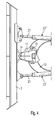
- a construction vehicle 1 has an implement 2 in which it is in particular a dozer blade or blade 3, with the help of a carrying and adjusting device 4 on the vehicle frame 5 arranged and movable, dad means swiveling and lifting and can be lowered.
- the construction vehicle 1 further comprises a chassis 6 with, for example two caterpillars 7 and an upper vehicle 8 with a driver's cab 9 and an engine 10.
- the carrying and adjusting device 4 has as load-bearing components for the shield a carrier 11 and a support piece 12.
- the shield 3 is articulated on the carrier 11 and the support piece 12 is on the Vehicle frame 5 articulated. Furthermore, the carrier 11 and the support piece 12 pivotally connected to each other.
- the linkage of the Shield 3 on the carrier 11 is along a perpendicular to the longitudinal axis of the vehicle 13 standing axis 14 (Fig. 1).
- the carrier 11 and that The support piece 12 is about an axis 15 which is parallel to the axis 14 pivotally connected to each other and the support piece 12 is on Vehicle frame 5 in the area of lateral cheeks 16 around a horizontal lying axis 17 movably mounted.
- One cheek 16 each is arranged laterally on the outside of the support piece 12 and lies in each case inside next to the caterpillars 7.
- the support piece 12 and with it the support 11 are about the axis 17 and the shield 3 can be raised and lowered.
- the hydraulic devices 20 attack each cheek 16.
- Hydraulic devices 23 are on both sides of the cheeks 16 hinged and serve to pivot the shield 3 around the Axis 14. This situation is shown in Fig. 2 and shows that the Shield 3 around the axis 14 from a middle position to the right and is pivotable to the left.
- the carrier 11 is in a central position to the construction vehicle 1 or relative to its vehicle longitudinal axis 13.
- the axis 15 about which the carrier 11 is pivotable on the support piece 12 is stored, does not intersect the vehicle longitudinal axis 13 (Fig. 2). she is off-center.
- a safety or blocking device 24 (Fig. 3) is provided.
- This securing and blocking device 24 either fixes the carrier 11 in the working position on the support piece 12 or releases the support 11 for pivoting about the axis 15. This case is shown in Fig. 5.
- the securing and blocking device 24 supports 11 releases, it is about the axis 15 from the position shown in FIG. 4 in the 5 pivotable position.
- the axis 14 moves in the process from their central position from the vehicle longitudinal axis 13 or from the vertical vehicle center plane to one side of the construction vehicle 1 out.
- the piston rod 21 can be hydraulic Device 23 '(Fig. 4) retracted and the other piston 21 of the other piston-cylinder device 23 ′′ as far as possible be extended (Fig. 5), so that the shield 3 in a to the left directed extreme position. He's only taking a small one now Width relative to the width of the construction vehicle 1.
- the securing and blocking device 24 is more expedient Way of at least one bolt 25 used for blocking or, according to the exemplary embodiment, of two for blocking Bolt 25 (Fig. 3) and a hydraulic device 26 which the Bolt 25 either pushes into carrier-side holding openings 27 or pulls out of these.
- the carrier 11 encompasses in the area of the securing and blocking device 24, the support piece 12 U-shaped, as shown in Fig. 3 is.
- the axis 14 also includes two spaced apart arranged bearing bolts 28 and 29. Your attachment to the carrier 11 and their shield-side connection is known to the person skilled in the art and shown specifically in Fig. 3.
- Carrier tabs 31 arranged on the shield side are in accordance with Embodiment also provided to both storage the bearing bolts 28 and 29 as well as in the region of the articulation points 30 to manufacture with the hydraulic devices 23.
- the Carrier 11 also encompass two shield-side support tabs 31 in a U-shape or it lies with a projection 32 between two shield-side Carrying tabs 31.
- the shield-side articulation point 33 for the Sloping maximum extendable piston rod 21 of the hydraulic Device 23 (Fig. 5) movable or at least partially detachable.
- the articulation point 33 is for the free end of the a piston rod 21 on a pivotable link 34, which in its Working position on the tab 31, for example with a bolt 35 can be blocked.
- the handlebar is used to tilt the plate 3 34 unlocked so that the freedom of movement of the shield 3 a little becomes larger than when the handlebar 34 is locked.
- the hydraulic devices used to adjust the shield 3 23 also change their position when the shield 3 is inclined relative to construction vehicle 1. You also take an inclined position a, as shown in Fig. 5.
- the support piece 12 is a projecting component on the vehicle frame 5. It can be arched (Fig. 5) and together with the cheeks 16 have an approximately U-shaped basic shape.
- a conventional sign 3 has a size corresponding to the representations 2, 4 and 5. Basically, a sign 3 'but also be a little bit larger and can be flanged on to the side Extension parts 40 and 41 are provided. Both that Center piece 42 of the shield 3 'and the two extension parts 40 and 41 each have ends facing one another Flange pieces 43, by means of which they can be connected to one another. This can be done with screws, not shown, and in the flange pieces 43 intended mounting openings 44 are used. Due to the Possibility of the plate 3 or 3 'extremely sloping for transport purposes to arrange to the construction vehicle can therefore also with regard to its Width 3 'changeable as required.
Landscapes
- Engineering & Computer Science (AREA)
- Mechanical Engineering (AREA)
- Mining & Mineral Resources (AREA)
- Civil Engineering (AREA)
- General Engineering & Computer Science (AREA)
- Structural Engineering (AREA)
- Body Structure For Vehicles (AREA)
- Shovels (AREA)
- Road Paving Machines (AREA)
- Road Repair (AREA)
Abstract
Description
Die Erfindung bezieht sich auf ein Baufahrzeug mit einem Arbeitsgerät, insbesondere einem Schild, das um eine vertikale Achse schwenkbar an einem Träger gelagert ist, der um eine horizontale Achse in vertikaler Richtung verschwenkbar am Fahrzeugrahmen gelagert ist, wobei die Schwenkbewegungen mittels hydraulischer Einrichtungen ausführbar sind.The invention relates to a construction vehicle with an implement, in particular a sign that can be swiveled around a vertical axis Carrier is mounted around a horizontal axis in the vertical direction is pivotally mounted on the vehicle frame, the pivoting movements are executable by means of hydraulic devices.
Das Baufahrzeug kann ein Fahrwerk mit Raupen oder mit bereiften Rädern aufweisen. Falls es sich um ein Fahrzeug mit Raupen handelt, so ist es in der Regel notwendig, dieses auf einem Tieflader zu der jeweiligen Baustelle zu transportieren. Mit Rädern versehene Baufahrzeuge können auch selbst zu den Baustellen gefahren werden, obwohl das meist unzweckmäßig ist. So werden Baufahrzeuge mit Rädern in Abhängigkeit von den zu bewältigenden Entfernungen ebenfalls auf Tiefladern transportiert. Bei einem derartigen Transport spielt die Breite des Arbeitsgerätes eine große Rolle. So kommt es immer wieder vor, dass das Arbeitsgerät, beispielsweise ein Schild von die Fahrzeugbreite übersteigender Länge, eine zu große Breite besitzt, so dass es vor dem Transport abmontiert und nachher wieder angebracht werden muß. Das ist mit einem hohen Aufwand verbunden.The construction vehicle can have a chassis with caterpillars or with tires exhibit. If it is a vehicle with caterpillars, it is in usually necessary, this on a flatbed truck to the respective construction site to transport. Wheeled construction vehicles can also do it themselves be driven to the construction sites, although this is usually inappropriate. So construction vehicles with wheels are dependent on those to be mastered Distances also transported on flatbed trucks. With such a Transport the width of the implement plays an important role. So it happens again and again that the implement, for example a Sign of length exceeding vehicle width, width too large has so that it is removed before transport and reattached afterwards must become. This involves a lot of effort.
Aus US 5 634 523 ist nicht nur das eingangs beschriebene Baufahrzeug mit einem Schild bekannt sondern auch bereits vorgesehen, den die Fahrzeugbreite übersteigenden Schild außermittig mit seitlichem Abstand zur Längsmittelebene des Fahrzeugs mit vertikaler Achse am Träger anzulenken, so dass der Schild um diese vertikale Achse in eine Transportstellung verschwenkt werden kann, in der sich der Schild innerhalb der Fahrzeugbreite befindet, ohne dass dazu ein sich übermäßig weit nach vorne erstreckender Träger bzw. eine in größerem Abstand vor dem Fahrzeug angeordnete vertikale Achse für den Schild vorgesehen sein muß. Der Abstand der vertikalen Achse zur Längsmittelebene des Fahrzeugs ist jedoch nicht veränderbar. Das bedeutet, dass während des Arbeitsbetriebs unsymmetrische Kraftverteilungen auftreten und aufzufangen sind, was verschleißfördernd wirkt.From US 5 634 523 is not only the construction vehicle described above known with a sign but also already provided the vehicle width overhanging sign off-center with lateral distance to Articulate the longitudinal median plane of the vehicle with the vertical axis on the carrier, so that the shield is in a transport position about this vertical axis can be pivoted in the sign within the vehicle width without being excessively far forward Carrier or one arranged at a greater distance in front of the vehicle vertical axis for the shield must be provided. The distance However, the vertical axis to the median longitudinal plane of the vehicle is not variable. That means that unbalanced during work Force distributions occur and are to be absorbed, which promotes wear acts.
Dementsprechend liegt der Erfindung die Aufgabe zugrunde, das Baufahrzeug so auszubilden, dass eine Breitenanpassung für den Transport vorgenommen werden kann, ohne dass dafür Nachteile im Arbeitsbetrieb in Kauf genommen werden müssen.Accordingly, the object of the invention is the construction vehicle to be trained in such a way that the width is adjusted for transport can be purchased without disadvantages in the work operation must be taken.
Diese Aufgabe wird erfindungsgemäß dadurch gelöst, dass die vertikale
Achse, um die das Arbeitsgerät schwenkbar ist, in seitlicher Richtung zwischen
einer durch die Fahrzeuglängsachse 13 verlaufenden vertikalen
Längsmittelebene und einer im Abstand parallel zur Längsmittelebene verlaufenden
Längsebene verstellbar ist.This object is achieved in that the vertical
Axis, about which the implement can be pivoted, in the lateral direction between
a vertical through the vehicle
Aus US 4 828 044 ist zwar ein Baufahrzeug bekannt, bei dem der Schild mittig am Träger mit einer in der Längsmittelebene des Fahrzeugs angeordneten vertikalen Achse angelenkt und diese in Querrichtung auslenkbar ist. Hierbei wird die vertikale Achse aber nicht parallel verlagert, sondern nur zur Seite hin gekippt, wobei die Achse in einem unteren Punkt mittels eines Kugelgelenks in der Längsmittelebene gehalten wird und mit einem oberen Bereich seitlich ausgeschwenkt wird. Diese Maßnahme dient dazu, den normalerweise waagerecht ausgerichteten Schild in einer Querebene in eine Schräglage zu verstellen. Mit einer Breitenanpassung zu Transportzwecken hat das nichts zu tun.From US 4,828,044 a construction vehicle is known in which the shield arranged centrally on the carrier with one in the longitudinal center plane of the vehicle vertical axis articulated and this can be deflected in the transverse direction. Here, the vertical axis is not shifted in parallel, but only tilted to the side, the axis at a lower point using a Ball joint is held in the longitudinal median plane and with an upper one Area is swung out sideways. This measure serves the usually level sign in a transverse plane into one To adjust the inclination. With a width adjustment for transport purposes it has nothing to do
Auf Grund der erfindungsgemäßen Ausbildung ist es möglich, für Transportzwecke die Anlenkstelle des Arbeitsgeräts zu verändern. Sie läßt sich z.B. derart zur Seite verlagern, dass das Arbeitsgerät in höherem Maße als bisher am Baufahrzeug verschwenkbar ist. Damit die Lage der Schwenkachse für das Arbeitsgerät aus ihrer mittigen Arbeitsposition in die seitliche Transportposition bewegbar ist, ist ferner vorgesehen, dass das als Träger für das Arbeitsgerät dienende Bauteil fahrzeugseitig verschwenkbar gelagert ist. Hierdurch läßt sich ein Schwenkradium erzielen, der nahezu der Länge des Trägers selbst entspricht. Die Folge hiervon ist, dass sich z.B. ein Schild trotz unmittelbarer Befestigung am Baufahrzeug extrem schräg zur Fahrzeuglängsrichtung einstellen läßt und dadurch weniger Platz in Breitenrichtung benötigt. Due to the training according to the invention, it is possible for transport purposes to change the articulation point of the implement. You can e.g. move to the side in such a way that the implement to a greater extent than is previously pivotable on the construction vehicle. So the location of the Swivel axis for the implement from its central working position in the lateral transport position is movable, it is further provided that the Carrier for the component serving the implement can be pivoted on the vehicle side is stored. This enables a swivel radius to be achieved which is almost the same Length of the carrier itself corresponds. The consequence of this is that e.g. a sign extremely oblique despite being directly attached to the construction vehicle to the vehicle's longitudinal direction and thus less space in the width direction needed.
Weitere Merkmale der Erfindung gehen aus Unteransprüchen und der Beschreibung in Verbindung mit der Zeichnung hervor.Further features of the invention are set out in the dependent claims and Description in connection with the drawing.
Die Erfindung wird nachstehend anhand eines Ausführungsbeispieles, das in der Zeichnung dargestellt ist, näher beschrieben. Dabei zeigen:
- Fig. 1
- eine Seitenansicht eines Raupen aufweisenden Baufahrzeuges mit einem Schild;
- Fig. 2:
- eine Draufsicht auf das Baufahrzeug gemäß Fig. 1
- Fig. 3:
- eine Seitenansicht des Schildes und der ihn tragenden Bauteile in größerem Maßstab;
- Fig. 4:
- eine Draufsicht auf den Schild und der ihn tragenden Bauteile in nochmals anderem Maßstab;
- Fig. 5:
- eine Draufsicht auf den Schild gemäß Fig. 4 in Schrägstellung;
- Fig. 6:
- eine Ansicht eines verlängerbaren Schildes vor dem Zusammenbau;
- Fig. 7:
- eine Draufsicht auf den Schild gemäß Fig. 6 vor dem Zusammenbau und
- Fig. 8:
- eine Seitenansicht des Schildes gemäß den Fig. 6 und 7.
- Fig. 1
- a side view of a crawler construction vehicle with a shield;
- Fig. 2:
- 2 shows a plan view of the construction vehicle according to FIG. 1
- Fig. 3:
- a side view of the shield and the components supporting it on a larger scale;
- Fig. 4:
- a plan view of the shield and the components supporting it in yet another scale;
- Fig. 5:
- a plan view of the shield of Figure 4 in an inclined position.
- Fig. 6:
- a view of an extendable shield before assembly;
- Fig. 7:
- a plan view of the shield of FIG. 6 before assembly and
- Fig. 8:
- a side view of the shield according to FIGS. 6 and 7.
Ein Baufahrzeug 1 weist gemäß Fig. 1 ein Arbeitsgerät 2 auf, bei dem
es sich insbesondere um einen Planierschild bzw. Schild 3 handelt,
der mit Hilfe einer Trage- und Verstelleinrichtung 4 am Fahrzeugrahmen
5 angeordnet und bewegbar, dad heißt schwenkbar sowie anhebbar
und absenkbar ist. According to FIG. 1, a construction vehicle 1 has an implement 2 in which
it is in particular a dozer blade or
Das Baufahrzeug 1 umfaßt ferner ein Fahrwerk 6 mit zum Beispiel
zwei Raupen 7 und ein Oberfahrzeug 8 mit einer Fahrerkabine 9 und
einem Motor 10.The construction vehicle 1 further comprises a
Die Trage- und Verstelleinrichtung 4 weist als tragende Bauteile für
den Schild einen Träger 11 und ein Tragestück 12 auf. Der Schild 3
ist an dem Träger 11 angelenkt und das Tragestück 12 ist an dem
Fahrzeugrahmen 5 angelenkt. Ferner sind der Träger 11 und das Tragestück
12 schwenkbar miteinander verbunden. Die Anlenkung des
Schildes 3 am Träger 11 erfolgt längs einer senkrecht zur Fahrzeuglängsachse
13 stehenden Achse 14 (Fig. 1). Der Träger 11 und das
Tragestück 12 sind um eine parallel zur Achse 14 stehende Achse 15
schwenkbar miteinander verbunden und das Tragestück 12 ist am
Fahrzeugrahmen 5 im Bereich von seitlichen Wangen 16 um eine horizontal
liegende Achse 17 bewegbar gelagert. Jeweils eine Wange 16
ist seitlich außen an dem Tragestück 12 angeordnet und liegt jeweils
innen neben den Raupen 7.The carrying and adjusting device 4 has as load-bearing components for
the shield a
Um die Achse 17 sind das Tragestück 12 und mit ihm der Träger 11
sowie der Schild 3 anhebbar und absenkbar. Dazu dienen aus Kolbenstange
18 und Zylinder 19 bestehende hydraulische Einrichtungen 20
auf beiden Seiten des Baufahrzeuges 1. Die hydraulischen Einrichtungen
20 greifen jeweils an den Wangen 16 an.The
Zwei weitere, ebenfalls aus Kolbenstange 21 und Zylinder 22 bestehende
hydraulische Einrichtungen 23 sind beidseitig an den Wangen
16 angelenkt und dienen zum Verschwenken des Schildes 3 um die
Achse 14. Diese Situation ist in Fig. 2 dargestellt und zeigt, daß der
Schild 3 um die Achse 14 aus einer mittleren Position nach rechts und
nach links verschwenkbar ist. Two more, also consisting of
Der Träger 11 befindet sich hierbei in einer mittigen Lage zum Baufahrzeug
1 bzw. relativ zu dessen Fahrzeuglängsachse 13.The
Die Achse 15, um die der Träger 11 schwenkbar am Tragestück 12
gelagert ist, schneidet nicht die Fahrzeuglängsachse 13 (Fig. 2). Sie
liegt außermittig.The
Damit der Träger 11 im normalen Betrieb nicht um die Achse 15 verschwenkbar
ist, ist ferner eine Sicherungs- bzw. Blockiereinrichtung
24 (Fig. 3) vorgesehen. Diese Sicherung- und Blockiereinrichtung 24
fixiert entweder den Träger 11 in der Arbeitsposition am Tragestück
12 oder gibt den Träger 11 zum Verschwenken um die Achse 15 frei.
Dieser Fall ist in Fig. 5 dargestellt.So that the
Sobald die Sicherungs- und Blockiereinrichtung 24 den Träger 11
freigibt, ist er um die Achse 15 aus der Position gemäß Fig. 4 in die
Position gemäß Fig. 5 verschwenkbar. Die Achse 14 bewegt sich dabei
aus ihrer mittigen Lage von der Fahrzeuglängsachse 13 bzw. aus der
senkrecht stehenden Fahrzeugmitteebene zu einer Seite des Baufahrzeuges
1 hin. Gleichzeitig kann die Kolbenstange 21 der einen hydraulischen
Einrichtung 23' (Fig. 4) eingezogen und die andere Kolben
21 der anderen Kolben-Zylindereinrichtung 23'' maximal weit
ausgefahren werden (Fig. 5), so daß der Schild 3 in eine nach links
gerichtete Extremposition gelangt. Er nimmt jetzt nur noch eine geringe
Breite relativ zur Breite des Baufahrzeuges 1 ein.As soon as the securing and blocking
Die Sicherungs- und Blockiereinrichtung 24 besteht zweckmäßiger
Weise aus mindestens einem zum Blockieren dienenden Bolzen 25
bzw. gemäß Ausführungsbeispiel aus zwei zum Blockieren dienenden
Bolzen 25 (Fig. 3) und einer hydraulischen Einrichtung 26, die die
Bolzen 25 entweder in trägerseitige Halteöffnungen 27 schiebt oder
aus diesen herauszieht. The securing and blocking
Der Träger 11 umgreift im Bereich der Sicherungs- und Blockiereinrichtung
24 das Tragestück 12 U-förmig, wie dies in Fig. 3 dargestellt
ist.The
Die Achse 14 umfaßt ferner gemäß Fig. 3 zwei im Abstand voneinander
angeordnete Lagerbolzen 28 und 29. Ihre Befestigung am Träger
11 und ihre schildseitige Verbindung ist dem Fachmann bekannt und
in Fig. 3 konkret dargestellt.3, the
Seitlich außen sowie bezüglich der Höhe zwischen den beiden Lagerbolzen
28 und 29 befinden sich Anlenkstellen 30 für die freien Enden
der Kolbenstangen 21 der beiden hydraulischen Einrichtungen 23
(Fig. 3 und 4). Schildseitig angeordnete Tragelaschen 31 sind gemäß
Ausführungsbeispiel ferner vorgesehen, um sowohl die Lagerung an
den Lagerbolzen 28 und 29 als auch im Bereich der Anlenkstellen 30
mit den hydraulischen Einrichtungen 23 herzustellen. Dabei kann der
Träger 11 zwei schildseitige Tragelaschen 31 auch U-förmig umgreifen
oder er liegt mit einem Vorsprung 32 zwischen zwei schildseitigen
Tragelaschen 31.Laterally outside and in terms of the height between the two bearing
Um eine optimale Schrägstellung des Schildes 3 zur Fahrzeuglängsachse
13 zu erzielen, ist die schildseitige Anlenkstelle 33 für die beim
Schrägstellen maximal ausfahrbare Kolbenstange 21 der hydraulischen
Einrichtung 23 (Fig. 5) bewegbar oder zumindest teilweise lösbar.
Konkret befindet sich die Anlenkstelle 33 für das freie Ende der
einen Kolbenstange 21 an einem schwenkbaren Lenker 34, der in seiner
Arbeitsposition an der Lasche 31 zum Beispiel mit einem Bolzen
35 blockierbar ist. Zum Schrägstellen des Schildes 3 wird der Lenker
34 entriegelt, so daß die Bewegungsfreiheit des Schildes 3 noch etwas
größer wird als bei verriegeltem Lenker 34.For an optimal inclination of the
Die zum Verstellen des Schildes 3 dienenden hydraulischen Einrichtungen
23 verändern beim Schrägstellen des Schildes 3 auch ihre Lage
relativ zum Baufahrzeug 1. Sie nehmen ebenfalls eine Schrägstellung
ein, wie dies in Fig. 5 dargestellt ist.The hydraulic devices used to adjust the
Das Tragestück 12 ist ein am Fahrzeugrahmen 5 vorstehendes Bauteil.
Es kann bogenförmig sein (Fig. 5) und zusammen mit den Wangen
16 eine etwa U-förmige Grundform besitzen.The
Ein üblicher Schild 3 weist etwa eine Größe entsprechend den Darstellungen
in den Fig. 2, 4 und 5 auf. Grundsätzlich kann ein Schild
3' aber auch noch etwas größer sein und dazu mit seitlich anflanschbaren
Verlängerungsteilen 40 und 41 versehen werden. Sowohl das
Mittelstück 42 des Schildes 3' als auch die beiden Verlängerungsteile
40 und 41 weisen an den einander zugewandten Enden jeweils
Flanschstücke 43 auf, mit deren Hilfe sie miteinander verbindbar sind.
Dazu können nicht dargestellte Schrauben und in den Flanschstücken
43 vorgesehene Befestigungsöffnungen 44 dienen. Aufgrund der
Möglichkeit, den Schild 3 bzw. 3' für Transportzweck extrem schräg
zum Baufahrzeug anzuordnen, kann daher auch ein bezüglich seiner
Breite je nach Bedarf veränderbarer Schild 3' vorgesehen sein.A
Claims (10)
Applications Claiming Priority (2)
| Application Number | Priority Date | Filing Date | Title |
|---|---|---|---|
| DE10116578 | 2001-03-29 | ||
| DE10116578A DE10116578A1 (en) | 2001-03-29 | 2001-03-29 | Construction vehicle with an implement |
Publications (2)
| Publication Number | Publication Date |
|---|---|
| EP1245740A1 true EP1245740A1 (en) | 2002-10-02 |
| EP1245740B1 EP1245740B1 (en) | 2010-04-14 |
Family
ID=7680210
Family Applications (1)
| Application Number | Title | Priority Date | Filing Date |
|---|---|---|---|
| EP02003871A Expired - Lifetime EP1245740B1 (en) | 2001-03-29 | 2002-02-21 | Working vehicle with a work implement |
Country Status (5)
| Country | Link |
|---|---|
| US (1) | US6719066B2 (en) |
| EP (1) | EP1245740B1 (en) |
| CA (1) | CA2377039C (en) |
| DE (2) | DE10116578A1 (en) |
| RU (1) | RU2243327C2 (en) |
Cited By (1)
| Publication number | Priority date | Publication date | Assignee | Title |
|---|---|---|---|---|
| US6719066B2 (en) * | 2001-03-29 | 2004-04-13 | Macmoter S.P.A. | Construction vehicle with a working appliance |
Families Citing this family (12)
| Publication number | Priority date | Publication date | Assignee | Title |
|---|---|---|---|---|
| AT500528B8 (en) * | 2004-10-07 | 2007-02-15 | Peter Doppler | DEVICE FOR RESTORING AND MANUFACTURING WEARABLE SURFACES |
| US7681337B2 (en) * | 2005-10-21 | 2010-03-23 | Batesville Services, Inc. | Plow with blade wing |
| US20070089327A1 (en) * | 2005-10-21 | 2007-04-26 | Watson Gary E | Plow with blade wing |
| US20080210446A1 (en) * | 2007-03-02 | 2008-09-04 | Deere & Company | Dozer blade tilt with independent functioning lift cylinders |
| US8607890B2 (en) * | 2009-09-18 | 2013-12-17 | Clark Equipment Company | Floating pivot joint for work implement |
| RU2459910C1 (en) * | 2011-02-14 | 2012-08-27 | Федеральное государственное бюджетное образовательное учреждение высшего профессионального образования "Ярославский государственный технический университет" | Bulldoser actuator |
| GB2491203B (en) * | 2011-05-27 | 2013-10-02 | Caterpillar Inc | Work machine blade coupling |
| US8418777B1 (en) * | 2011-12-09 | 2013-04-16 | GK Machine, Inc. | Agricultural folding scraper blade |
| GB2500250A (en) * | 2012-03-16 | 2013-09-18 | Pearson Eng Ltd | Mounting assembly for mounting implement to a vehicle |
| US10167893B2 (en) * | 2016-04-05 | 2019-01-01 | Caterpillar Global Mining Llc | Stopper assembly for an implement of a machine |
| MX2019012666A (en) * | 2017-05-02 | 2020-07-22 | Gomaco Corp | Freesteering system for mobile machines. |
| RU2770854C1 (en) * | 2021-10-20 | 2022-04-22 | Федеральное государственное бюджетное образовательное учреждение высшего образования "Ярославский государственный технический университет" ФГБОУВО "ЯГТУ" | Bulldozer equipment |
Citations (9)
| Publication number | Priority date | Publication date | Assignee | Title |
|---|---|---|---|---|
| US2386025A (en) * | 1942-10-09 | 1945-10-02 | Standard Steel Works | Mounting for road rollers and similar devices |
| US3670825A (en) * | 1969-10-09 | 1972-06-20 | Caterpillar Tractor Co | Power angling bulldozer |
| EP0140139A2 (en) * | 1983-09-21 | 1985-05-08 | Erich Prinoth | Smooth shield for a snow vehicle |
| DE4305648A1 (en) * | 1992-02-24 | 1994-02-10 | Josef Nusser | Swivelling mechanism for front mounted snow plough or road sweeper - comprises articulated rectangular shaped framework fixed to back of plough and front of vehicle |
| EP0587175A1 (en) * | 1992-09-11 | 1994-03-16 | MARTIN BEILHACK MASCHINENFABRIK UND HAMMERWERK GmbH | Snow-plough |
| US5634523A (en) * | 1993-06-29 | 1997-06-03 | Kabushiki Kaisha Komatsu Seisakusho | Blade device |
| US5638618A (en) * | 1996-06-07 | 1997-06-17 | Blizzard Corporation | Adjustable wing plow |
| WO1997041309A1 (en) * | 1996-04-25 | 1997-11-06 | Walter Zaugg-Siegenthaler | Method and device for guiding a work implement |
| US5974702A (en) * | 1998-06-01 | 1999-11-02 | Donoghue; John Barry | Snow plow mounting assembly |
Family Cites Families (23)
| Publication number | Priority date | Publication date | Assignee | Title |
|---|---|---|---|---|
| US3645340A (en) * | 1969-11-05 | 1972-02-29 | Case Co J I | Control system for a dozer blade |
| US3759110A (en) * | 1972-01-10 | 1973-09-18 | Case Co J I | Hydraulic angle dozer |
| US4076080A (en) * | 1974-10-21 | 1978-02-28 | Milton I. Larson | Front end loader attachment |
| US4083414A (en) * | 1975-12-30 | 1978-04-11 | Kabushiki Kaisha Komatsu Seisakusho | Combination angling-tilting bulldozer |
| CA1034376A (en) * | 1976-03-26 | 1978-07-11 | J.I. Case Company | Angle control for dozer blade |
| US4081036A (en) * | 1976-07-20 | 1978-03-28 | Kabushiki Kaisha Komatsu Seisakusho | Mounting arrangement for supporting bulldozer blade |
| IT1203190B (en) * | 1978-07-10 | 1989-02-15 | Fiat Allis Macch Movi | EARTH-MOVING MACHINE OF THE SCRAPING BLADE TYPE |
| US4281721A (en) * | 1978-12-12 | 1981-08-04 | Beales Steel Products Ltd. | Bulldozer blade mounting assembly |
| US4248311A (en) * | 1979-04-02 | 1981-02-03 | J. I. Case Company | Side shift blade arrangement |
| US4405019A (en) * | 1981-09-04 | 1983-09-20 | J. I. Case Company | Adjustment and stabilizer mechanism for dozer blade |
| AT379836B (en) * | 1982-07-30 | 1986-03-10 | Bombardier Rotax Wien | DEVICE FOR FASTENING A WORK TOOL ON A VEHICLE |
| US4828044A (en) * | 1987-08-07 | 1989-05-09 | J. I. Case Company | Dozer blade mounting assembly |
| US4828045A (en) * | 1987-11-09 | 1989-05-09 | J. I. Case Company | Dozer blade visual tilt indicator |
| US4834191A (en) * | 1987-12-22 | 1989-05-30 | Vecchio Charles J | Plow for motor grader |
| US5241763A (en) * | 1991-12-17 | 1993-09-07 | Dynan David R | Plow attachment |
| US5285588A (en) * | 1992-07-13 | 1994-02-15 | W. Wally Niemela | Winged plow |
| US5507352A (en) * | 1994-10-25 | 1996-04-16 | Case Corporation | Block apparatus and method for changing dozer blade pitch |
| US5706591A (en) * | 1996-03-13 | 1998-01-13 | Wissmiller; Joseph E. | Hitch for a moldboard snow plow |
| US5899007A (en) * | 1996-06-07 | 1999-05-04 | Blizzard Corporation | Adjustable wing plow |
| US5813476A (en) * | 1996-11-06 | 1998-09-29 | Semper; Luis O. | Blade mounting structure |
| US6393737B2 (en) * | 1999-02-03 | 2002-05-28 | Blizzard Corporation | Plow support assembly |
| US6178669B1 (en) * | 1999-02-03 | 2001-01-30 | Blizzard Corporation | Plow hitch assembly for vehicles |
| DE10116578A1 (en) * | 2001-03-29 | 2002-10-10 | Macmoter Spa | Construction vehicle with an implement |
-
2001
- 2001-03-29 DE DE10116578A patent/DE10116578A1/en not_active Ceased
-
2002
- 2002-02-21 DE DE50214351T patent/DE50214351D1/en not_active Expired - Lifetime
- 2002-02-21 EP EP02003871A patent/EP1245740B1/en not_active Expired - Lifetime
- 2002-03-15 CA CA2377039A patent/CA2377039C/en not_active Expired - Fee Related
- 2002-03-26 US US10/108,942 patent/US6719066B2/en not_active Expired - Fee Related
- 2002-03-29 RU RU2002107955/03A patent/RU2243327C2/en not_active IP Right Cessation
Patent Citations (9)
| Publication number | Priority date | Publication date | Assignee | Title |
|---|---|---|---|---|
| US2386025A (en) * | 1942-10-09 | 1945-10-02 | Standard Steel Works | Mounting for road rollers and similar devices |
| US3670825A (en) * | 1969-10-09 | 1972-06-20 | Caterpillar Tractor Co | Power angling bulldozer |
| EP0140139A2 (en) * | 1983-09-21 | 1985-05-08 | Erich Prinoth | Smooth shield for a snow vehicle |
| DE4305648A1 (en) * | 1992-02-24 | 1994-02-10 | Josef Nusser | Swivelling mechanism for front mounted snow plough or road sweeper - comprises articulated rectangular shaped framework fixed to back of plough and front of vehicle |
| EP0587175A1 (en) * | 1992-09-11 | 1994-03-16 | MARTIN BEILHACK MASCHINENFABRIK UND HAMMERWERK GmbH | Snow-plough |
| US5634523A (en) * | 1993-06-29 | 1997-06-03 | Kabushiki Kaisha Komatsu Seisakusho | Blade device |
| WO1997041309A1 (en) * | 1996-04-25 | 1997-11-06 | Walter Zaugg-Siegenthaler | Method and device for guiding a work implement |
| US5638618A (en) * | 1996-06-07 | 1997-06-17 | Blizzard Corporation | Adjustable wing plow |
| US5974702A (en) * | 1998-06-01 | 1999-11-02 | Donoghue; John Barry | Snow plow mounting assembly |
Cited By (1)
| Publication number | Priority date | Publication date | Assignee | Title |
|---|---|---|---|---|
| US6719066B2 (en) * | 2001-03-29 | 2004-04-13 | Macmoter S.P.A. | Construction vehicle with a working appliance |
Also Published As
| Publication number | Publication date |
|---|---|
| US6719066B2 (en) | 2004-04-13 |
| US20020139545A1 (en) | 2002-10-03 |
| DE10116578A1 (en) | 2002-10-10 |
| DE50214351D1 (en) | 2010-05-27 |
| CA2377039C (en) | 2011-05-24 |
| CA2377039A1 (en) | 2002-09-29 |
| RU2243327C2 (en) | 2004-12-27 |
| EP1245740B1 (en) | 2010-04-14 |
Similar Documents
| Publication | Publication Date | Title |
|---|---|---|
| DE19631042C5 (en) | Road construction machines for roadworks | |
| CH650299A5 (en) | SCREW EXCAVATOR. | |
| DE1944214B2 (en) | RAILLESS MOVABLE ROTARY CRANE UNDERCARRIAGE | |
| DE2658250A1 (en) | MOBILE AND LIFTING BASKET | |
| EP3793929B1 (en) | Vehicle crane comprising a movable adapter between the main boom and the main boom extension | |
| EP1245740A1 (en) | Working vehicle with a work implement | |
| DE2363755C2 (en) | Crawler vehicle with four crawler units | |
| DE9213091U1 (en) | Rotary harrow | |
| EP2042410B1 (en) | Agricultural vehicle | |
| EP0065118A2 (en) | Excavator | |
| EP1676772A2 (en) | Working machine, in particular sieving machine | |
| EP1023825A1 (en) | Suspension and working device or vehicle | |
| DE3032112C2 (en) | Connection device for attaching agricultural machinery to a tractor | |
| CH697556B1 (en) | Excavator has chassis and pivot mounting with rotating assembly bearing, where two chassis sections are arranged to tilt around rotational axis tilted against each other | |
| DE2322504A1 (en) | SELF-PROPELLED ARTICULATED VEHICLE | |
| DE102005037389B4 (en) | Multi-purpose working device | |
| AT396798B (en) | CONSTRUCTION MACHINE WITH AN ATTACHMENT | |
| EP0594160A1 (en) | Machine for use in tree nurseries, gardens and the like | |
| DE19620944C1 (en) | Support device with transverse motion drive for mobile work equipment | |
| DE4407695A1 (en) | Trailer mount for land or construction site use | |
| DE9414597U1 (en) | Drawn mower | |
| DE894565C (en) | Wedge-shaped, front-mounted snow plow that can be pivoted laterally around a pivot shaft arranged in front of the vehicle | |
| DE2710320A1 (en) | Bulldozer with scraper blade fully adjustable from cabin - has hydraulic cylinders to raise and lower and incline blade to vehicle axis | |
| AT379629B (en) | EXCAVATOR | |
| DE10219214B4 (en) | Articulated construction vehicle |
Legal Events
| Date | Code | Title | Description |
|---|---|---|---|
| PUAI | Public reference made under article 153(3) epc to a published international application that has entered the european phase |
Free format text: ORIGINAL CODE: 0009012 |
|
| AK | Designated contracting states |
Kind code of ref document: A1 Designated state(s): AT BE CH CY DE DK ES FI FR GB GR IE IT LI LU MC NL PT SE TR |
|
| AX | Request for extension of the european patent |
Free format text: AL;LT;LV;MK;RO;SI |
|
| 17P | Request for examination filed |
Effective date: 20021211 |
|
| AKX | Designation fees paid |
Designated state(s): DE FR GB IT |
|
| 17Q | First examination report despatched |
Effective date: 20070927 |
|
| GRAP | Despatch of communication of intention to grant a patent |
Free format text: ORIGINAL CODE: EPIDOSNIGR1 |
|
| GRAS | Grant fee paid |
Free format text: ORIGINAL CODE: EPIDOSNIGR3 |
|
| GRAA | (expected) grant |
Free format text: ORIGINAL CODE: 0009210 |
|
| AK | Designated contracting states |
Kind code of ref document: B1 Designated state(s): DE FR GB IT |
|
| REG | Reference to a national code |
Ref country code: GB Ref legal event code: FG4D Free format text: NOT ENGLISH |
|
| REF | Corresponds to: |
Ref document number: 50214351 Country of ref document: DE Date of ref document: 20100527 Kind code of ref document: P |
|
| PLBE | No opposition filed within time limit |
Free format text: ORIGINAL CODE: 0009261 |
|
| STAA | Information on the status of an ep patent application or granted ep patent |
Free format text: STATUS: NO OPPOSITION FILED WITHIN TIME LIMIT |
|
| 26N | No opposition filed |
Effective date: 20110117 |
|
| PGFP | Annual fee paid to national office [announced via postgrant information from national office to epo] |
Ref country code: FR Payment date: 20110301 Year of fee payment: 10 Ref country code: IT Payment date: 20110223 Year of fee payment: 10 |
|
| PGFP | Annual fee paid to national office [announced via postgrant information from national office to epo] |
Ref country code: GB Payment date: 20110221 Year of fee payment: 10 |
|
| GBPC | Gb: european patent ceased through non-payment of renewal fee |
Effective date: 20120221 |
|
| REG | Reference to a national code |
Ref country code: FR Ref legal event code: ST Effective date: 20121031 |
|
| PG25 | Lapsed in a contracting state [announced via postgrant information from national office to epo] |
Ref country code: IT Free format text: LAPSE BECAUSE OF NON-PAYMENT OF DUE FEES Effective date: 20120221 |
|
| PG25 | Lapsed in a contracting state [announced via postgrant information from national office to epo] |
Ref country code: FR Free format text: LAPSE BECAUSE OF NON-PAYMENT OF DUE FEES Effective date: 20120229 Ref country code: GB Free format text: LAPSE BECAUSE OF NON-PAYMENT OF DUE FEES Effective date: 20120221 |
|
| REG | Reference to a national code |
Ref country code: DE Ref legal event code: R119 Ref document number: 50214351 Country of ref document: DE Ref country code: DE Ref legal event code: R409 Ref document number: 50214351 Country of ref document: DE |
|
| REG | Reference to a national code |
Ref country code: DE Ref legal event code: R409 Ref document number: 50214351 Country of ref document: DE |
|
| REG | Reference to a national code |
Ref country code: DE Ref legal event code: R082 Ref document number: 50214351 Country of ref document: DE Representative=s name: TERGAU & WALKENHORST PATENTANWAELTE - RECHTSAN, DE |
|
| REG | Reference to a national code |
Ref country code: DE Ref legal event code: R081 Ref document number: 50214351 Country of ref document: DE Owner name: ANDOR GMBH, DE Free format text: FORMER OWNER: MACMOTER S.P.A., MODIGLIANA, IT Effective date: 20140107 Ref country code: DE Ref legal event code: R082 Ref document number: 50214351 Country of ref document: DE Representative=s name: TERGAU & WALKENHORST PATENTANWAELTE - RECHTSAN, DE Effective date: 20140107 Ref country code: DE Ref legal event code: R081 Ref document number: 50214351 Country of ref document: DE Owner name: ANDOR GMBH, DE Free format text: FORMER OWNER: MACMOTER S.P.A., MODIGLIANA, FORLI, IT Effective date: 20140107 Ref country code: DE Ref legal event code: R082 Ref document number: 50214351 Country of ref document: DE Representative=s name: TERGAU & WALKENHORST PATENTANWAELTE PARTGMBB, DE Effective date: 20140107 |
|
| PGFP | Annual fee paid to national office [announced via postgrant information from national office to epo] |
Ref country code: DE Payment date: 20150224 Year of fee payment: 14 |
|
| REG | Reference to a national code |
Ref country code: DE Ref legal event code: R119 Ref document number: 50214351 Country of ref document: DE |
|
| PG25 | Lapsed in a contracting state [announced via postgrant information from national office to epo] |
Ref country code: DE Free format text: LAPSE BECAUSE OF NON-PAYMENT OF DUE FEES Effective date: 20160901 |