EP1245692A2 - Remote spray coating of nuclear cross-under piping - Google Patents
Remote spray coating of nuclear cross-under piping Download PDFInfo
- Publication number
- EP1245692A2 EP1245692A2 EP01203080A EP01203080A EP1245692A2 EP 1245692 A2 EP1245692 A2 EP 1245692A2 EP 01203080 A EP01203080 A EP 01203080A EP 01203080 A EP01203080 A EP 01203080A EP 1245692 A2 EP1245692 A2 EP 1245692A2
- Authority
- EP
- European Patent Office
- Prior art keywords
- pipe
- carriage
- machine
- support bar
- center portion
- Prior art date
- Legal status (The legal status is an assumption and is not a legal conclusion. Google has not performed a legal analysis and makes no representation as to the accuracy of the status listed.)
- Granted
Links
Images


Classifications
-
- C—CHEMISTRY; METALLURGY
- C23—COATING METALLIC MATERIAL; COATING MATERIAL WITH METALLIC MATERIAL; CHEMICAL SURFACE TREATMENT; DIFFUSION TREATMENT OF METALLIC MATERIAL; COATING BY VACUUM EVAPORATION, BY SPUTTERING, BY ION IMPLANTATION OR BY CHEMICAL VAPOUR DEPOSITION, IN GENERAL; INHIBITING CORROSION OF METALLIC MATERIAL OR INCRUSTATION IN GENERAL
- C23C—COATING METALLIC MATERIAL; COATING MATERIAL WITH METALLIC MATERIAL; SURFACE TREATMENT OF METALLIC MATERIAL BY DIFFUSION INTO THE SURFACE, BY CHEMICAL CONVERSION OR SUBSTITUTION; COATING BY VACUUM EVAPORATION, BY SPUTTERING, BY ION IMPLANTATION OR BY CHEMICAL VAPOUR DEPOSITION, IN GENERAL
- C23C4/00—Coating by spraying the coating material in the molten state, e.g. by flame, plasma or electric discharge
- C23C4/12—Coating by spraying the coating material in the molten state, e.g. by flame, plasma or electric discharge characterised by the method of spraying
- C23C4/14—Coating by spraying the coating material in the molten state, e.g. by flame, plasma or electric discharge characterised by the method of spraying for coating elongate material
- C23C4/16—Wires; Tubes
-
- B—PERFORMING OPERATIONS; TRANSPORTING
- B05—SPRAYING OR ATOMISING IN GENERAL; APPLYING FLUENT MATERIALS TO SURFACES, IN GENERAL
- B05B—SPRAYING APPARATUS; ATOMISING APPARATUS; NOZZLES
- B05B13/00—Machines or plants for applying liquids or other fluent materials to surfaces of objects or other work by spraying, not covered by groups B05B1/00 - B05B11/00
- B05B13/06—Machines or plants for applying liquids or other fluent materials to surfaces of objects or other work by spraying, not covered by groups B05B1/00 - B05B11/00 specially designed for treating the inside of hollow bodies
- B05B13/0627—Arrangements of nozzles or spray heads specially adapted for treating the inside of hollow bodies
- B05B13/0636—Arrangements of nozzles or spray heads specially adapted for treating the inside of hollow bodies by means of rotatable spray heads or nozzles
-
- B—PERFORMING OPERATIONS; TRANSPORTING
- B08—CLEANING
- B08B—CLEANING IN GENERAL; PREVENTION OF FOULING IN GENERAL
- B08B9/00—Cleaning hollow articles by methods or apparatus specially adapted thereto
- B08B9/02—Cleaning pipes or tubes or systems of pipes or tubes
- B08B9/027—Cleaning the internal surfaces; Removal of blockages
- B08B9/04—Cleaning the internal surfaces; Removal of blockages using cleaning devices introduced into and moved along the pipes
- B08B9/049—Cleaning the internal surfaces; Removal of blockages using cleaning devices introduced into and moved along the pipes having self-contained propelling means for moving the cleaning devices along the pipes, i.e. self-propelled
-
- B—PERFORMING OPERATIONS; TRANSPORTING
- B05—SPRAYING OR ATOMISING IN GENERAL; APPLYING FLUENT MATERIALS TO SURFACES, IN GENERAL
- B05B—SPRAYING APPARATUS; ATOMISING APPARATUS; NOZZLES
- B05B13/00—Machines or plants for applying liquids or other fluent materials to surfaces of objects or other work by spraying, not covered by groups B05B1/00 - B05B11/00
- B05B13/02—Means for supporting work; Arrangement or mounting of spray heads; Adaptation or arrangement of means for feeding work
- B05B13/04—Means for supporting work; Arrangement or mounting of spray heads; Adaptation or arrangement of means for feeding work the spray heads being moved during spraying operation
- B05B13/0405—Means for supporting work; Arrangement or mounting of spray heads; Adaptation or arrangement of means for feeding work the spray heads being moved during spraying operation with reciprocating or oscillating spray heads
-
- G—PHYSICS
- G21—NUCLEAR PHYSICS; NUCLEAR ENGINEERING
- G21C—NUCLEAR REACTORS
- G21C17/00—Monitoring; Testing ; Maintaining
- G21C17/017—Inspection or maintenance of pipe-lines or tubes in nuclear installations
-
- Y—GENERAL TAGGING OF NEW TECHNOLOGICAL DEVELOPMENTS; GENERAL TAGGING OF CROSS-SECTIONAL TECHNOLOGIES SPANNING OVER SEVERAL SECTIONS OF THE IPC; TECHNICAL SUBJECTS COVERED BY FORMER USPC CROSS-REFERENCE ART COLLECTIONS [XRACs] AND DIGESTS
- Y10—TECHNICAL SUBJECTS COVERED BY FORMER USPC
- Y10S—TECHNICAL SUBJECTS COVERED BY FORMER USPC CROSS-REFERENCE ART COLLECTIONS [XRACs] AND DIGESTS
- Y10S118/00—Coating apparatus
- Y10S118/10—Pipe and tube inside
Definitions
- the present invention relates to a remote mechanical positioner for use with a thermal spray coating process. Radial and axial velocities and acceleration, parameters which are critical to uniform application of the coating, are controlled using programmed stepper motors. Recent applications of the thermal spray coating process include nuclear turbine cross-under piping.
- the positioning machine is modular and can be easily installed through a 12 x 18-inch manway opening typically found in the cross-under piping.
- Thermal spray coating has been a well-known useful technology for many years, as described in Thermal Spray Technology, "Equipment and Theory"; R. W. Smith, Materials Engineering Institute, pp. 1-3 (1993), and includes combustion coating; plasma coating and electric/wire-arc coating.
- the primary application has been the coating of large digester tanks found in papermills. Recently, it has been thought useful for the inside of nuclear turbine cross-under piping for corrosion-erosion protection. Coating the inside of these pipes is, however, a very labor-intensive job. The surface to be coated must be first cleaned by conventional abrasive blasting to remove scale and surface contaminants.
- a profile abrasive is pressure-blasted onto the surface to produce a white-metal clean surface with a 0.0025cm to 0.0127cm (3 to 5 mil) anchor tooth profile surface finish.
- the surface must be thermal spray coated within four hours or an oxide (rust) will form on the surface inhibiting the bond quality of the thermal spray coating, which is typically a corrosion-erosion resistant material.
- Thermal spraying which includes plasma spraying and other coating processes such as combustion flame and electric/wire arc, is a well-known coating technique described, for example, in U.S. Patent Specifications: 3,839,618; 4,649,858; 5,452,854; and 5,837,959 (Muehlberger; Sakai et al.; Keller; and Muehlberger, et al., respectively).
- the person doing the thermal spray coating has to work on his knees inside a 91 1 ⁇ 2 cm (36-inch) diameter pipe wearing a blasting hood with a separate breathing supply. It is a physically demanding job that requires frequent rest periods, especially when the worker is abrasive blasting or thermal spraying overhead. Visibility is also a problem during either the abrasive blast-cleaning, profiling, or thermal spraying operations.
- the process generates a fair amount of smoke, and the actual thermal spray process literally produces a fountain of molten and particles, which are propelled against the surface to be coating using pressurized air or an inert gas. Approximately 20% of these molten particles wind up on the bottom of the pipe and must be cleaned up with a suitable vacuum cleaner.
- the main feature needed for the design is the ability to easily pass all parts of the machine through the 12 x 18-inch (30.5 x 45.7 cm) elliptical manway, and then assemble them in the cross-under pipe.
- a machine for coating the interior surface of a hollow, axially elongated pipe characterized by comprising: a center portion of a support bar which can be aligned concentric with the centerline of the pipe; at least two tripods having at least three legs to contact the interior of the pipe and support the center portion of the support bar; at least one moveable carriage which can travel axially within the pipe, rotatably attached to the center portion of the support bar, said carriage containing at least one thermal spray coating device which extends from the carriage towards the interior of the pipe; a source of thermal sprayable material; a motor to drive the carriage axially; a motor to rotate the center portion of support bar and the carriage; a programmable controller external to the pipe which is capable of controlling the motors and thermal spray coating device.
- all interior components of the coating apparatus are themselves protected, typically with an abrasion resistant plastic material.
- the extension thermal spray device is adjustable in increments.
- This provides a programmable thermal spraying apparatus for use in the interior of conduits such as axially elongated pipes that can be aligned concentric with the centerline of the pipe and which is adjustable and can coat the inside of the pipe.
- the same machine can also contain an abrasion cleaning/profiling head to first clean the pipe before coating it.
- the main features of the machine 10 include the following design features as shown in Fig. 1. All components are double sealed against the ingress of blasting grit and profiling hardened particles. Sealing is accomplished by double lip seals backed up with felt seals on all rotating surfaces where grit penetration could jam or wear the components.
- the outer surfaces of the two tripod assemblies and 2 and 4, axial motor 6, rotation motor 8, and moveable axial carriage 12 are coated with polyurethane. Tests have shown that the sand and hardened grit simply bounce off the polyurethane thereby completely protecting the aluminum directly underneath the polyurethane.
- the machine is supported on two adjustable tripod assemblies which are directly adjustable to work in a pipe 14 from 32 to about 48 inches (81 to about 123 cm), and beyond, inside diameter.
- a rubber bellows (not shown in Fig. 1) can be used to fit over each tripod leg and prevent the entry of grit into the telescoping legs.
- the center support bar 16 can be a 2.5-inch (6.35 cm) square 0.105-inch (0.26 cm) wall steel tube which can be assembled in any convenient incremental lengths from up to 10 foot (254 cm) long sections typically 5 to 10 foot (152 to 254 cm) sections, which rigidly snap together to form a smooth centered shaft.
- the six tripod legs 18 have adjustable levelers 20 so that the square tube can be aligned concentric with the centerline 22-22 of the pipe 14.
- the square tube slides into the left tripod support and is held in axial position by a shaft clamp.
- the center of the tripod rotates on Kaydon slim-line bearings which permit full 360-degree rotation of the center shaft.
- the Kaydon bearings are pre-loaded against each other to eliminate play and backlash.
- the right tripod support 2 is similar to the left in construction except that it also supports the rotation and axial position motors 8 and 6 respectively. Both of these motors are Compumotor Microstepping motors. Each has 10,000 steps per revolution, which means that all motion factors such as speed, acceleration, peak velocity, and reverse times can be totally and accurately controlled via a programmable controller. This is very important from the standpoint of consistent, repeatable thermal spray coating application. Each motor couples directly to a gearbox to increase torque and generate the optimum spray rate. The axial position gearbox ratio is 50:1 which translates into up to 9 inches (22.8 cm) per second of axial travel.
- the rotation axis uses a harmonic drive gearbox with zero backlash (160:1) ratio resulting in tangential speeds of up to 3 ft. (91 cm) per second.
- the harmonic gear reducer contains a flexspline (an elliptical, nonrigid external gear), a circular spline (a round, rigid internal gear), and a wave generator (an elliptical ball bearing assembly).
- the elliptical wave generator input deflects the flexspline to engage teeth at the major axis.
- the flexspline teeth at minor axis are fully disengaged - where most of the relative motion between teeth occurs.
- the flexspline output rotates in opposite direction to input.
- the rigid circular spline is rotationally fixed.
- the teeth on the nonrigid flexspline and the rigid circular spline are in continuous engagement. Since the flexspline has two teeth fewer than the circular spline, one revolution of the input causes relative motion between the flexspline and the circular spline equal to two teeth. With the circular spline rotationally fixed, the flexspline rotates in the opposite direction to the input at a reduction ratio equal to one-half the number of teeth on the flexspline. This relative rotation may be seen by examining the motion of a single flexspline tooth over one-half an input revolution. The tooth is fully engaged when the major axis of the wave generator input is at 0°.
- the axial carriage 12 rides on the chrome plated steel center tube 16.
- the aluminum housing of the carriage which is polyurethane coated to prevent erosion houses eight polyurethane rollers which roll on the square tube. This housing is pulled along the square tube by a friction-type cable, sprocket chain assembly or other similar type drive 24 which was selected due to its ability to continue to operate with all the abrasive particles present. There are no gears or ball screws to jam with grit.
- the axial carriage has felt wipers, shown generally at 26, to knock the grit off the square tube so the polyurethane wheels ride on a grit-free surface.
- Fig. 1 shows the thermal spray gun 28 attached to the arm on the axial carriage. The manway is shown as 29.
- Fig. 2 shows that if the same arm and drive system operates slowly enough, approximately one inch (2.54 cm) per second peak absolute speed, an abrasion cleaning profiling operation with abrasive grit, using the profiling head 30 can be accomplished.
- the programmable stepper motors can be programmed to move at any desired speed, less than 2.5 cm of arm tip movement per second all the way up to top speeds of 3 feet (91.4 cm) per second.
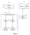
- the control system for the mechanical delivery apparatus consists of a computer controlled, closed loop motion control, and a video inspection camera, not shown in the figures, for remote viewing of the thermal spray operation.
- Fig. 3 shows the block diagram of the control system.
- a 2-axis motion control system is shown as 40 with a display 42, keypad 44 connected in a motion controller 46 which controls motor drives 48 and motor encoders 50.
- a video control 60 contains control 62, video monitor 64 and pan/tilt camera 66.
- the circumferential and axial drives of the thermal spray system both use stepper motors, and the advantage of stepper motors is that they are brushless and will be able to handle the quick changing of direction that is required in the thermal spray operation.
- Each stepper motor has encoders on them that are fed to the motion controller and provide position and speed information.
- the motion controller is the intelligence of the system and has a computer built into it.
- the motion controller has the ability to operate as an embedded system, where as soon as the system is turned on it will automatically run the computer program for that system.
- the motion controller has built-in safety features: it can detect motor stalls, it has over current and over speed trip points, and it can detect an operator emergency stop condition.
- the embedded computer program is stored on battery backed RAM so the program remains even when power is removed from the motion controller.
- the motion controller communicates with the operator through the use of the display and keypad. Through this interface the operator will set up the system parameters depending on whether the system is blasting, profiling or thermal spraying the pipe.
- an additional feature of the control system is the use of a visual system for remotely observing the mechanical system during operation.
- the remote visual system is needed because the operator of the control system is outside of the pipe and during operation will not be able to directly observe the tool. If any part of the operation is malfunctioning it is important for the operator to quickly stop the operation of the tool.
- the visual system consists of a color CCD camera that has a remote focus, auto iris, and zooming capabilities and is mounted in a protective housing.
- the camera can also mount on a platform that can pan and tilt the camera.
- the controls for the camera and the pan/tilt units are mounted in the control system housing which also contains the video monitor.
- the hardware for the motion control and video systems are mounted in a portable enclosure that can be moved around to the proper viewing location.
Landscapes
- Engineering & Computer Science (AREA)
- Chemical & Material Sciences (AREA)
- Mechanical Engineering (AREA)
- Physics & Mathematics (AREA)
- Plasma & Fusion (AREA)
- Chemical Kinetics & Catalysis (AREA)
- Materials Engineering (AREA)
- Metallurgy (AREA)
- Organic Chemistry (AREA)
- Coating By Spraying Or Casting (AREA)
- Spray Control Apparatus (AREA)
Abstract
Description
Claims (12)
- A machine (10) for coating the interior surface of a hollow, axially elongated pipe (14) comprising:(a) a center portion of at least one support bar (16) which can be aligned concentric with the centerline (22) of the pipe (14);(b) at least two tripods having at least three legs (18) to contact the interior of the pipe and support the center portion of the support bar (16);(c) at least one moveable carriage (12) which can travel axially within the pipe (14), rotatably attached to the center portion of the support bar (16), said carriage containing at least one thermal spray coating device (28) which extends from the carriage to the interior of the pipe;(d) a source of thermal sprayable material;(e) a motor (6) to drive the carriage (12) axially;(f) a motor (8) to rotate the center portion of support bar (16) and the carriage (12);(g) a programmable controller (40) external to the pipe which is capable of controlling the motors and thermal spray coating device.
- The machine of Claim 1, wherein all interior components of the coating machine are themselves coated with an abrasion resistant plastic material.
- The machine of Claim 1, wherein the moveable carriage (12) also contains an abrasion cleaning profiling head (30).
- The machine of Claim 1, where all interior components are coated with polyurethane abrasion resistant material.
- The machine of Claim 1, where the legs of the tripod are telescoping legs covered with rubber, and where both motors (6,8) are brushless microstepping motors.
- The machine of Claim 1, where the carriage (12) is moved along the support bar (16) by a friction cable drive.
- The machine of Claim 1, where the carriage is moved along the support bar by a sprocket chain assembly.
- The machine of Claim 1, also containing a video inspection camera.
- The machine of Claim 1, where the thermal (28) spray device is an electric/wire arc coating device.
- The machine of Claim 1, operating inside a pipe (14) to thermal spray a coating on the inside of a pipe, where the thermal spray coating device (28) is adjustable in increments.
- A method of coating an interior surface of a hollow, axially elongated pipe (14), with a machine (10) comprising:(a) a center portion of at least one support bar (16) which can be aligned concentric with the centerline (22) of the pipe (14);(b) at least two tripods having at least three legs (18) to contact the interior of the pipe and support the center portion of the support bar (16);(c)at least one moveable carriage (12) which can travel axially within the pipe (14), rotatably attached to the center portion of the support bar (16), said carriage containing at least one thermal spray coating device (28) which extends from the carriage to the interior of the pipe;(d) a source of thermal sprayable material;(e) a motor (6) to drive the carriage (12) axially;(f) a motor (8) to rotate the center portion of support bar (16) and the carriage (12);(g) a programmable controller (40) external to the pipe which is capable of controlling the motors and thermal spray coating device;
the method comprising the steps of:(1) driving the carriage; and,(2) controlling the thermal spray coating device under the control of the controller; whereby to coat the interior surface. - A method in accordance with claim 11 further comprising the step of programming the programmable controller.
Applications Claiming Priority (2)
| Application Number | Priority Date | Filing Date | Title |
|---|---|---|---|
| US09/821,974 US6508413B2 (en) | 2000-04-06 | 2001-03-30 | Remote spray coating of nuclear cross-under piping |
| US821974 | 2001-03-30 |
Publications (3)
| Publication Number | Publication Date |
|---|---|
| EP1245692A2 true EP1245692A2 (en) | 2002-10-02 |
| EP1245692A3 EP1245692A3 (en) | 2004-02-04 |
| EP1245692B1 EP1245692B1 (en) | 2006-11-29 |
Family
ID=25234754
Family Applications (1)
| Application Number | Title | Priority Date | Filing Date |
|---|---|---|---|
| EP01203080A Expired - Lifetime EP1245692B1 (en) | 2001-03-30 | 2001-08-13 | Remote spray coating of nuclear cross-under piping |
Country Status (3)
| Country | Link |
|---|---|
| US (1) | US6508413B2 (en) |
| EP (1) | EP1245692B1 (en) |
| DE (1) | DE60124858T2 (en) |
Cited By (4)
| Publication number | Priority date | Publication date | Assignee | Title |
|---|---|---|---|---|
| EP1486755A3 (en) * | 2003-06-06 | 2005-03-30 | Breval Technical Services Limited | Conduit inspection apparatus and method |
| US7181985B2 (en) | 2005-05-27 | 2007-02-27 | Breval Technical Services Limited | Conduit inspection apparatus and method |
| EP2503208A1 (en) | 2011-03-23 | 2012-09-26 | Entreprise Philippe Lassarat | System for maintenance of inner conduit surface and related process |
| CN106670030A (en) * | 2016-12-25 | 2017-05-17 | 重庆市永川区泰兴机械厂 | Spraying devices for pipeline inner wall |
Families Citing this family (64)
| Publication number | Priority date | Publication date | Assignee | Title |
|---|---|---|---|---|
| US7126303B2 (en) * | 2003-07-08 | 2006-10-24 | Board Of Regents Of The University Of Nebraska | Robot for surgical applications |
| US7042184B2 (en) * | 2003-07-08 | 2006-05-09 | Board Of Regents Of The University Of Nebraska | Microrobot for surgical applications |
| US20080058989A1 (en) * | 2006-04-13 | 2008-03-06 | Board Of Regents Of The University Of Nebraska | Surgical camera robot |
| US7960935B2 (en) | 2003-07-08 | 2011-06-14 | The Board Of Regents Of The University Of Nebraska | Robotic devices with agent delivery components and related methods |
| KR100662341B1 (en) * | 2004-07-09 | 2007-01-02 | 엘지전자 주식회사 | Display device and its color reproduction method |
| US20060283981A1 (en) * | 2005-06-16 | 2006-12-21 | Mead William T | Spray coating nozzle assembly for coating remote areas |
| JP2007050469A (en) * | 2005-08-17 | 2007-03-01 | Hitachi Plant Technologies Ltd | Blasting device and blasting method |
| CA2861159C (en) * | 2006-06-22 | 2018-02-27 | Board Of Regents Of The University Of Nebraska | Magnetically coupleable robotic devices and related methods |
| US8679096B2 (en) | 2007-06-21 | 2014-03-25 | Board Of Regents Of The University Of Nebraska | Multifunctional operational component for robotic devices |
| US9579088B2 (en) | 2007-02-20 | 2017-02-28 | Board Of Regents Of The University Of Nebraska | Methods, systems, and devices for surgical visualization and device manipulation |
| US20080001005A1 (en) * | 2006-07-02 | 2008-01-03 | Lance Weaver | Apparatus for evenly applying liquids to interior surfaces |
| CA2690808C (en) | 2007-07-12 | 2016-09-27 | Board Of Regents Of The University Of Nebraska | Methods and systems of actuation in robotic devices |
| EP2178431A4 (en) * | 2007-08-15 | 2017-01-18 | Board of Regents of the University of Nebraska | Medical inflation, attachment, and delivery devices and related methods |
| WO2009023851A1 (en) * | 2007-08-15 | 2009-02-19 | Board Of Regents Of The University Of Nebraska | Modular and cooperative medical devices and related systems and methods |
| US7971497B2 (en) * | 2007-11-26 | 2011-07-05 | Air Products And Chemicals, Inc. | Devices and methods for performing inspections, repairs, and/or other operations within vessels |
| US20100012751A1 (en) * | 2008-07-16 | 2010-01-21 | Warren Marc R | Laser Assisted Aiming System for Fluid Nozzles |
| US9114458B2 (en) * | 2009-08-21 | 2015-08-25 | Illinois Tool Works Inc. | Pipe end machining device with axial autofeed |
| US8978579B2 (en) | 2009-11-04 | 2015-03-17 | Ingeníera y Marketing, S.A. | Method and device for regenerating the interior surfaces of conduits by means of thermal spraying of metals |
| WO2011075693A1 (en) * | 2009-12-17 | 2011-06-23 | Board Of Regents Of The University Of Nebraska | Modular and cooperative medical devices and related systems and methods |
| CA2804176A1 (en) | 2010-08-06 | 2013-02-05 | Board Of Regents Of The University Of Nebraska | Methods and systems for handling or delivering materials for natural orifice surgery |
| EP4275634A3 (en) | 2011-06-10 | 2024-01-10 | Board of Regents of the University of Nebraska | Surgical end effector |
| WO2013009887A1 (en) | 2011-07-11 | 2013-01-17 | Board Of Regents Of The University Of Nebraska | Robotic surgical devices, systems and related methods |
| US8800396B2 (en) | 2011-07-14 | 2014-08-12 | Crts, Inc. | Pipeline internal field joint cleaning, coating, and inspection robot |
| EP3730031A1 (en) | 2011-10-03 | 2020-10-28 | Board of Regents of the University of Nebraska | Robotic surgical devices and systems |
| WO2013106569A2 (en) | 2012-01-10 | 2013-07-18 | Board Of Regents Of The University Of Nebraska | Methods, systems, and devices for surgical access and insertion |
| US9498292B2 (en) | 2012-05-01 | 2016-11-22 | Board Of Regents Of The University Of Nebraska | Single site robotic device and related systems and methods |
| JP6228196B2 (en) | 2012-06-22 | 2017-11-08 | ボード オブ リージェンツ オブ ザ ユニバーシティ オブ ネブラスカ | Locally controlled robotic surgical device |
| US9770305B2 (en) | 2012-08-08 | 2017-09-26 | Board Of Regents Of The University Of Nebraska | Robotic surgical devices, systems, and related methods |
| EP2882331A4 (en) | 2012-08-08 | 2016-03-23 | Univ Nebraska | ROBOTIC SURGICAL SYSTEMS AND DEVICES, AND ASSOCIATED METHODS |
| US12295680B2 (en) | 2012-08-08 | 2025-05-13 | Board Of Regents Of The University Of Nebraska | Robotic surgical devices, systems and related methods |
| US20140196662A1 (en) * | 2012-12-21 | 2014-07-17 | Fluor Technologies Corporation | Nanoclad Pipe Weld Repair, Systems and Methods |
| CA2906672C (en) | 2013-03-14 | 2022-03-15 | Board Of Regents Of The University Of Nebraska | Methods, systems, and devices relating to force control surgical systems |
| CA2905948C (en) | 2013-03-14 | 2022-01-11 | Board Of Regents Of The University Of Nebraska | Methods, systems, and devices relating to robotic surgical devices, end effectors, and controllers |
| US10667883B2 (en) | 2013-03-15 | 2020-06-02 | Virtual Incision Corporation | Robotic surgical devices, systems, and related methods |
| JP6479790B2 (en) | 2013-07-17 | 2019-03-06 | ボード オブ リージェンツ オブ ザ ユニバーシティ オブ ネブラスカ | Robotic surgical device, system and related methods |
| MX370557B (en) | 2013-10-03 | 2019-12-17 | Illinois Tool Works | Pivotal tool support for a pipe machining apparatus. |
| WO2015052353A1 (en) | 2013-10-07 | 2015-04-16 | Ingenieria Y Marketing, S.A. | Method and device for inspecting and restoring ducts |
| DE102013223688A1 (en) * | 2013-11-20 | 2015-05-21 | Siemens Aktiengesellschaft | Method and device for the automated application of a spray coating |
| US20150197840A1 (en) * | 2014-01-10 | 2015-07-16 | United Technologies Corporation | Systems and methods for removing overspray |
| WO2015197570A1 (en) * | 2014-06-25 | 2015-12-30 | Siemens Aktiengesellschaft | Device for radially supporting and damping a rod-like component in a cavity and method for mounting the device |
| JP6710199B2 (en) | 2014-09-12 | 2020-06-17 | ボード オブ リージェンツ オブ ザ ユニバーシティ オブ ネブラスカ | Quick release end effector and related systems and methods |
| EP3217890B1 (en) | 2014-11-11 | 2020-04-08 | Board of Regents of the University of Nebraska | Robotic device with compact joint design |
| EP4555965A3 (en) | 2015-08-03 | 2025-07-02 | Virtual Incision Corporation | Robotic surgical devices, systems and related methods |
| GB2545223A (en) * | 2015-12-09 | 2017-06-14 | Rtl Mat Ltd | Apparatus and methods for joining in a tube |
| US10751136B2 (en) | 2016-05-18 | 2020-08-25 | Virtual Incision Corporation | Robotic surgical devices, systems and related methods |
| FR3052533B1 (en) | 2016-06-13 | 2018-11-16 | Battakarst | PROJECTION BELL OF GRENAULES AND SUCTION OF THE PROJECTED GRENAULTS, ROBOT FOR THE RENOVATION OF FORCEED CONDUITS, PROVIDED WITH ONE SUCH BELL |
| EP3503829A4 (en) | 2016-08-25 | 2020-04-15 | Board of Regents of the University of Nebraska | QUICK RELEASE TOOL CONNECTOR AND RELATED SYSTEMS AND METHODS |
| EP4699745A3 (en) | 2016-08-30 | 2026-04-29 | Board of Regents of the University of Nebraska | Robotic device with compact joint design and an additional degree of freedom |
| CN106540831B (en) * | 2016-11-07 | 2018-11-30 | 江苏龙冶节能科技有限公司 | A kind of even application device of raw coke over gas riser Nano self-cleaning coating |
| CN115337111B (en) | 2016-11-22 | 2025-04-25 | 内布拉斯加大学董事会 | Improved coarse positioning device and related system and method |
| CN110462259B (en) | 2016-11-29 | 2022-10-28 | 虚拟切割有限公司 | User controller with user presence detection and related systems and methods |
| WO2018112199A1 (en) | 2016-12-14 | 2018-06-21 | Virtual Incision Corporation | Releasable attachment device for coupling to medical devices and related systems and methods |
| CN111417333B (en) | 2017-09-27 | 2023-08-29 | 虚拟切割有限公司 | Robotic surgical device with tracking camera technology and related systems and methods |
| CN117140580A (en) | 2018-01-05 | 2023-12-01 | 内布拉斯加大学董事会 | Single-arm robotic device with compact joint design and related systems and methods |
| GB201806071D0 (en) | 2018-04-13 | 2018-05-30 | Rolls Royce Power Eng Plc | Apparatus |
| CN121714364A (en) | 2019-01-07 | 2026-03-24 | 虚拟切割有限公司 | Robotic-assisted surgery systems and related devices and methods |
| CN110216033A (en) * | 2019-05-29 | 2019-09-10 | 江苏吉鑫风能科技股份有限公司 | A kind of elongated bore Workpiece painting constructing device and the spraying method using it |
| CN110258733B (en) * | 2019-06-13 | 2021-02-02 | 云数势能科技(深圳)有限公司 | Automatic pipeline cleaning device who changes |
| CN111136072A (en) * | 2020-01-12 | 2020-05-12 | 景高平 | A new type of pipeline dredging equipment |
| CN115843233A (en) | 2020-07-06 | 2023-03-24 | 虚拟切割有限公司 | Surgical robot positioning system and related devices and methods |
| CN113499901B (en) * | 2021-06-09 | 2022-05-24 | 浙江乐歌智能驱动科技有限公司 | Equipment for spraying lubricating grease on inner wall of pipe |
| KR102502764B1 (en) * | 2021-07-16 | 2023-02-23 | 주식회사 에스엠뿌레 | Nozzle assembly for sprayer |
| CN115382708B (en) * | 2022-09-29 | 2023-06-02 | 广东华晟安全职业评价有限公司 | An anti-corrosion spraying device for oil and gas transportation pipelines |
| CN115627437B (en) * | 2022-11-02 | 2024-05-24 | 中国石油大学(华东) | A device for preparing a metal coating on the inner surface of a small diameter pipe |
Family Cites Families (20)
| Publication number | Priority date | Publication date | Assignee | Title |
|---|---|---|---|---|
| US3071107A (en) * | 1960-09-29 | 1963-01-01 | Richard C Stanley | Pipe coating apparatus |
| NL123054C (en) * | 1962-10-10 | |||
| US3839618A (en) | 1972-01-03 | 1974-10-01 | Geotel Inc | Method and apparatus for effecting high-energy dynamic coating of substrates |
| US3960644A (en) * | 1974-09-25 | 1976-06-01 | Mcfadden Eldon C | Pipe lining apparatus |
| US4036173A (en) * | 1975-07-21 | 1977-07-19 | Nicklas Manfred E | Internal coating and sandblasting bug for pipe |
| DE7722908U1 (en) * | 1977-07-22 | 1977-11-24 | Castolin Gmbh, 6000 Frankfurt | Device for automatic build-up welding |
| US4164325A (en) * | 1977-11-21 | 1979-08-14 | Watson John D | High-pressure-rotary-nozzle apparatus |
| US4337723A (en) * | 1980-12-15 | 1982-07-06 | Davis J C | Pipe interior surface coating device |
| JPH065155B2 (en) | 1984-10-12 | 1994-01-19 | 住友金属工業株式会社 | Furnace wall repair device for kiln |
| JPS61186466A (en) * | 1985-02-15 | 1986-08-20 | Purazumeito:Kk | Plasma thermal spraying method of inner wall of tubular structural body |
| US4869936A (en) * | 1987-12-28 | 1989-09-26 | Amoco Corporation | Apparatus and process for producing high density thermal spray coatings |
| GB9202088D0 (en) * | 1992-01-31 | 1992-03-18 | Thomas Robert E | The manufacture of cylindrical components by centrifugal force |
| DE4240991A1 (en) | 1992-12-05 | 1994-06-09 | Plasma Technik Ag | Plasma spray gun |
| CA2119430A1 (en) * | 1993-04-20 | 1994-10-21 | Joseph P. Mercurio | Dense oxide coatings by thermal spraying |
| US5837959A (en) | 1995-09-28 | 1998-11-17 | Sulzer Metco (Us) Inc. | Single cathode plasma gun with powder feed along central axis of exit barrel |
| US5796064A (en) * | 1996-10-29 | 1998-08-18 | Ingersoll-Rand Company | Method and apparatus for dual coat thermal spraying cylindrical bores |
| US5829461A (en) * | 1997-01-10 | 1998-11-03 | Ramsey; Donald | Interior tank cleaning apparatus |
| US5913977A (en) * | 1998-03-25 | 1999-06-22 | Neuco, Inc. | Apparatus and method for internally coating live gas pipe joints or other discontinuities |
| US6051803A (en) | 1998-08-11 | 2000-04-18 | Hale, Jr.; Dorr E. | Pipe cutting apparatus |
| US6171398B1 (en) | 1999-04-12 | 2001-01-09 | Donald W. Hannu | Apparatus for coating a conduit surface |
-
2001
- 2001-03-30 US US09/821,974 patent/US6508413B2/en not_active Expired - Lifetime
- 2001-08-13 EP EP01203080A patent/EP1245692B1/en not_active Expired - Lifetime
- 2001-08-13 DE DE60124858T patent/DE60124858T2/en not_active Expired - Lifetime
Cited By (6)
| Publication number | Priority date | Publication date | Assignee | Title |
|---|---|---|---|---|
| EP1486755A3 (en) * | 2003-06-06 | 2005-03-30 | Breval Technical Services Limited | Conduit inspection apparatus and method |
| US7181985B2 (en) | 2005-05-27 | 2007-02-27 | Breval Technical Services Limited | Conduit inspection apparatus and method |
| EP2503208A1 (en) | 2011-03-23 | 2012-09-26 | Entreprise Philippe Lassarat | System for maintenance of inner conduit surface and related process |
| FR2973096A1 (en) * | 2011-03-23 | 2012-09-28 | Entpr Philippe Lassarat | INTERIOR WALL MAINTENANCE SYSTEM OF A CONDUCT AND METHOD OF IMPLEMENTING THE SAME |
| CN106670030A (en) * | 2016-12-25 | 2017-05-17 | 重庆市永川区泰兴机械厂 | Spraying devices for pipeline inner wall |
| CN106670030B (en) * | 2016-12-25 | 2018-10-19 | 重庆市永川区泰兴机械厂 | Pipe inner-wall spraying device |
Also Published As
| Publication number | Publication date |
|---|---|
| DE60124858D1 (en) | 2007-01-11 |
| US6508413B2 (en) | 2003-01-21 |
| EP1245692A3 (en) | 2004-02-04 |
| EP1245692B1 (en) | 2006-11-29 |
| DE60124858T2 (en) | 2007-05-31 |
| US20020003173A1 (en) | 2002-01-10 |
Similar Documents
| Publication | Publication Date | Title |
|---|---|---|
| US6508413B2 (en) | Remote spray coating of nuclear cross-under piping | |
| US10864640B1 (en) | Articulating arm programmable tank cleaning nozzle | |
| US12090502B2 (en) | Movable electro-hydraulic composite drive spraying robot with large working space | |
| US4690159A (en) | Rotary cleaning device | |
| US20100139019A1 (en) | Cleaning Apparatus for Large Diameter Pipe | |
| US20190374984A1 (en) | Programmable Railcar Tank Cleaning System | |
| CA1319504C (en) | Apparatus for coating internal surfaces | |
| KR101429935B1 (en) | Moving mechanism for blast gun for blasting machine | |
| US20070296964A1 (en) | Inspection apparatus | |
| KR20200035622A (en) | the robot for washing ring shape space of korean steam generator | |
| KR100464462B1 (en) | Blasting apparatus using method of vacuum adsorbing | |
| KR100501927B1 (en) | suspended type painting apparatus | |
| GB2160131A (en) | Hand-held blasting apparatus | |
| CN106737622B (en) | Sand blasting robot | |
| JP2006315176A (en) | Robot arm | |
| JPH08141534A (en) | Pipe cleaning robot | |
| CN119634130A (en) | Support device, nuclear power plant penetration casing grinding and painting device and method | |
| JP2645312B2 (en) | Method and apparatus for spraying cycloids using twin guns | |
| US9827650B2 (en) | Surface media blaster | |
| CN215744378U (en) | Gate panel spraying device | |
| JP2004338071A (en) | Hollow wrist of industrial robot and industrial robot | |
| US11745309B1 (en) | Remotely operated abrasive blasting apparatus, system, and method | |
| JPH019671Y2 (en) | ||
| JP2952057B2 (en) | Bellows cleaning device | |
| JPH07167982A (en) | Inspection system for loop chamber interior of nuclear power plant |
Legal Events
| Date | Code | Title | Description |
|---|---|---|---|
| PUAI | Public reference made under article 153(3) epc to a published international application that has entered the european phase |
Free format text: ORIGINAL CODE: 0009012 |
|
| AK | Designated contracting states |
Kind code of ref document: A2 Designated state(s): AT BE CH CY DE DK ES FI FR GB GR IE IT LI LU MC NL PT SE TR |
|
| AX | Request for extension of the european patent |
Free format text: AL;LT;LV;MK;RO;SI |
|
| PUAL | Search report despatched |
Free format text: ORIGINAL CODE: 0009013 |
|
| AK | Designated contracting states |
Kind code of ref document: A3 Designated state(s): AT BE CH CY DE DK ES FI FR GB GR IE IT LI LU MC NL PT SE TR |
|
| AX | Request for extension of the european patent |
Extension state: AL LT LV MK RO SI |
|
| 17P | Request for examination filed |
Effective date: 20040113 |
|
| 17Q | First examination report despatched |
Effective date: 20040826 |
|
| AKX | Designation fees paid |
Designated state(s): DE FR GB IT |
|
| RAP1 | Party data changed (applicant data changed or rights of an application transferred) |
Owner name: SIEMENS POWER GENERATION, INC. |
|
| GRAP | Despatch of communication of intention to grant a patent |
Free format text: ORIGINAL CODE: EPIDOSNIGR1 |
|
| GRAS | Grant fee paid |
Free format text: ORIGINAL CODE: EPIDOSNIGR3 |
|
| GRAA | (expected) grant |
Free format text: ORIGINAL CODE: 0009210 |
|
| AK | Designated contracting states |
Kind code of ref document: B1 Designated state(s): DE FR GB IT |
|
| REG | Reference to a national code |
Ref country code: GB Ref legal event code: FG4D |
|
| REF | Corresponds to: |
Ref document number: 60124858 Country of ref document: DE Date of ref document: 20070111 Kind code of ref document: P |
|
| ET | Fr: translation filed | ||
| PLBE | No opposition filed within time limit |
Free format text: ORIGINAL CODE: 0009261 |
|
| STAA | Information on the status of an ep patent application or granted ep patent |
Free format text: STATUS: NO OPPOSITION FILED WITHIN TIME LIMIT |
|
| 26N | No opposition filed |
Effective date: 20070830 |
|
| REG | Reference to a national code |
Ref country code: DE Ref legal event code: R081 Ref document number: 60124858 Country of ref document: DE Owner name: SIEMENS ENERGY, INC.(N.D. GES.D. STAATES DELAW, US Free format text: FORMER OWNER: SIEMENS POWER GENERATION, INC., ORLANDO, FLA., US Effective date: 20110516 |
|
| REG | Reference to a national code |
Ref country code: FR Ref legal event code: CD Owner name: SIEMENS ENERGY, INC. Effective date: 20120413 |
|
| PGFP | Annual fee paid to national office [announced via postgrant information from national office to epo] |
Ref country code: FR Payment date: 20140812 Year of fee payment: 14 Ref country code: GB Payment date: 20140815 Year of fee payment: 14 |
|
| PGFP | Annual fee paid to national office [announced via postgrant information from national office to epo] |
Ref country code: IT Payment date: 20140826 Year of fee payment: 14 |
|
| GBPC | Gb: european patent ceased through non-payment of renewal fee |
Effective date: 20150813 |
|
| PG25 | Lapsed in a contracting state [announced via postgrant information from national office to epo] |
Ref country code: IT Free format text: LAPSE BECAUSE OF NON-PAYMENT OF DUE FEES Effective date: 20150813 |
|
| REG | Reference to a national code |
Ref country code: FR Ref legal event code: ST Effective date: 20160429 |
|
| PG25 | Lapsed in a contracting state [announced via postgrant information from national office to epo] |
Ref country code: GB Free format text: LAPSE BECAUSE OF NON-PAYMENT OF DUE FEES Effective date: 20150813 |
|
| PG25 | Lapsed in a contracting state [announced via postgrant information from national office to epo] |
Ref country code: FR Free format text: LAPSE BECAUSE OF NON-PAYMENT OF DUE FEES Effective date: 20150831 |
|
| PGFP | Annual fee paid to national office [announced via postgrant information from national office to epo] |
Ref country code: DE Payment date: 20161020 Year of fee payment: 16 |
|
| REG | Reference to a national code |
Ref country code: DE Ref legal event code: R119 Ref document number: 60124858 Country of ref document: DE |
|
| PG25 | Lapsed in a contracting state [announced via postgrant information from national office to epo] |
Ref country code: DE Free format text: LAPSE BECAUSE OF NON-PAYMENT OF DUE FEES Effective date: 20180301 |