EP1245344A2 - Reintegration of a digital camera in an image processing system which is deplaced from a calibrated position in a non-calibrated position - Google Patents
Reintegration of a digital camera in an image processing system which is deplaced from a calibrated position in a non-calibrated position Download PDFInfo
- Publication number
- EP1245344A2 EP1245344A2 EP02003694A EP02003694A EP1245344A2 EP 1245344 A2 EP1245344 A2 EP 1245344A2 EP 02003694 A EP02003694 A EP 02003694A EP 02003694 A EP02003694 A EP 02003694A EP 1245344 A2 EP1245344 A2 EP 1245344A2
- Authority
- EP
- European Patent Office
- Prior art keywords
- camera
- workpiece
- cameras
- equation
- offset
- Prior art date
- Legal status (The legal status is an assumption and is not a legal conclusion. Google has not performed a legal analysis and makes no representation as to the accuracy of the status listed.)
- Granted
Links
Images
Classifications
-
- B—PERFORMING OPERATIONS; TRANSPORTING
- B25—HAND TOOLS; PORTABLE POWER-DRIVEN TOOLS; MANIPULATORS
- B25J—MANIPULATORS; CHAMBERS PROVIDED WITH MANIPULATION DEVICES
- B25J9/00—Programme-controlled manipulators
- B25J9/16—Programme controls
- B25J9/1694—Programme controls characterised by use of sensors other than normal servo-feedback from position, speed or acceleration sensors, perception control, multi-sensor controlled systems, sensor fusion
-
- B—PERFORMING OPERATIONS; TRANSPORTING
- B25—HAND TOOLS; PORTABLE POWER-DRIVEN TOOLS; MANIPULATORS
- B25J—MANIPULATORS; CHAMBERS PROVIDED WITH MANIPULATION DEVICES
- B25J9/00—Programme-controlled manipulators
- B25J9/16—Programme controls
- B25J9/1679—Programme controls characterised by the tasks executed
- B25J9/1692—Calibration of manipulator
-
- G—PHYSICS
- G01—MEASURING; TESTING
- G01B—MEASURING LENGTH, THICKNESS OR SIMILAR LINEAR DIMENSIONS; MEASURING ANGLES; MEASURING AREAS; MEASURING IRREGULARITIES OF SURFACES OR CONTOURS
- G01B11/00—Measuring arrangements characterised by the use of optical techniques
- G01B11/002—Measuring arrangements characterised by the use of optical techniques for measuring two or more coordinates
-
- G—PHYSICS
- G05—CONTROLLING; REGULATING
- G05B—CONTROL OR REGULATING SYSTEMS IN GENERAL; FUNCTIONAL ELEMENTS OF SUCH SYSTEMS; MONITORING OR TESTING ARRANGEMENTS FOR SUCH SYSTEMS OR ELEMENTS
- G05B2219/00—Program-control systems
- G05B2219/30—Nc systems
- G05B2219/39—Robotics, robotics to robotics hand
- G05B2219/39039—Two cameras detect same reference on workpiece to define its position in space
Definitions
- the invention relates to a method for reintegrating digital cameras given focal length in an image processing system, for subsequent Determination of the position of a workpiece and the position of features of the Workpiece in 3D space using at least two electronic Cameras and digital image processing, in which the cameras on one common world coordinate system are calibrated and then the Workpiece is placed in the space between the cameras, at least one of the cameras previously from a calibrated, known position ( ⁇ A ⁇ ) has been translated into an uncalibrated, unknown position ( ⁇ B ⁇ ), according to the preamble of claim 1.
- the camera positions in advance from the image data of a calibration body or a calibration board.
- Such a process has become known from EP 763 406 A1 in order to manipulate a Workpiece to perform with several interacting with it spatially separated electronic cameras with image processing.
- Each of the at least three spatially separated cameras take one when they are measured your assigned calibration chart with dot patterns, their pictures and the Dot pattern for determining the position of the individual camera in the room processed and their location saved.
- a measurement of the Calibration tables are separated from each other, these values also get saved. Then the body to be measured is placed in the room spent between the cameras.
- a disadvantage of this method is principally that for determining the location of a body in space Calibration boards are used, which must be handled with care and must not be damaged as they also need storage space.
- the main disadvantage is that the calibration boards with a lot of effort must be positioned mechanically in the field of view of the cameras and the Positionability must be extremely repeatable. This reproducibility Ensuring positioning is often associated with considerable costs because the spatial conditions, for example in conveyor technology, are often difficult are.
- the video images and the coordinates of the features of the The workpiece in a coordinate system of the workpiece is represented by a Calculator using the method of bundle compensation to position the workpiece in World coordinates as well as the position of the features of the workpiece in World coordinates calculated.
- the invention has for its object to provide a method with which reintegrates an adjusted camera into the old, non-adjusted position can become what is supposed to happen in a mathematical way, without the pretended Camera new thanks to calibration panels inserted in the production cell calibrated and calculated or measured again using a theodolite got to.
- the object is that, in order to establish the relationship between the world coordinate system ( ⁇ W ⁇ ) and the camera coordinate system ( ⁇ K ⁇ ), at least two measurement marks which have not been measured and are not known in either of the two coordinate systems are introduced as a fixed point in each camera image of each camera.
- the method according to the invention has the advantage that with the same from not in the world coordinate system as well as in the camera coordinate system measured fixed points by reintegrating an adjusted camera Mathematical calculation is carried out without the camera being adjusted calibration plates again inserted in the production cell and recalibrated must be calculated or remeasured using a theodolite.
- such measuring marks are used Fixed points selected that are independent of the workpiece and, for example, on Bottom of the manufacturing cell are arranged, in which is to be measured Workpiece is located.
- this is preferably at a working distance from the camera to the one to be measured Workpiece carried out, which is relatively large to offset the camera, for example, the working distance of the camera is several meters Compared to a few millimeters offset of the camera.
- the A , B ⁇ i are the unknown lengths of the vectors A, B p i from camera position ⁇ A ⁇ or ⁇ B ⁇ to the i-th measuring marks.
- a nonlinear system of equations can be used with the standardized imaging beams can be determined according to equation 4, which with standard methods, such as Linearization according to Newton and compensation calculation, with e.g. SVD decomposition, too solve is.
- the table shows the additional error after an impact against the Reintegration camera is to be expected.
- the object of the invention is particularly in automated production from e.g. Vehicle bodies for detecting the position detection of the Workpiece, in the field of calibration of autonomous mobile systems with cameras, especially with CCD sensors, can be used to create a digital Camera moving from a calibrated position to an uncalibrated position has been relocated, for example by a blow or impact, back into the Image processing system for position detection with a defined coordinate system to reintegrate. It is particularly advantageous that the adjusted Do not recalibrate the camera again using calibration boards or one Theodolites must be measured again.
Abstract
Description
Die Erfindung betrifft ein Verfahren zur Reintegration digitaler Kameras mit gegebener Brennweite in ein Bildverarbeitungssystem, zur nachfolgenden Bestimmung der Position eines Werkstücks und der Position von Merkmalen des Werkstücks im 3D-Raum unter Verwendung von mindestens zwei elektronischen Kameras und digitaler Bildverarbeitung, bei welchem die Kameras auf ein gemeinsames Weltkoordinatensystem kalibriert werden und anschließend das Werkstück in den Raum zwischen den Kameras verbracht wird, wobei wenigstens eine der Kameras zuvor aus einer kalibrierten, bekannten Position ({A}) translatorisch in eine unkalibrierte, unbekannte Position ({B}) versetzt worden ist, gemäß dem Oberbegriff des Anspruchs 1.The invention relates to a method for reintegrating digital cameras given focal length in an image processing system, for subsequent Determination of the position of a workpiece and the position of features of the Workpiece in 3D space using at least two electronic Cameras and digital image processing, in which the cameras on one common world coordinate system are calibrated and then the Workpiece is placed in the space between the cameras, at least one of the cameras previously from a calibrated, known position ({A}) has been translated into an uncalibrated, unknown position ({B}), according to the preamble of claim 1.
In der automatisierten Fertigung von z.B. Fahrzeugkarossen ist die digitale Bildverarbeitung heute Stand der Technik. Eine zentrale Anwendung in diesem Prozess ist die Positionserkennung des Werkstückes. Hierbei sehen kalibrierte Kameras auf das zu bearbeitende Objekt. Aus den sich ergebenden Pixeldaten bestimmter Objektmerkmale wird hiernach die 3-D-Werkstückpose in einem definierten Koordinatensystem berechnet.In the automated production of e.g. Vehicle bodywork is digital image processing State of the art today. A key application in this The process is the position detection of the workpiece. Here calibrated see Cameras on the object to be processed. From the resulting pixel data The 3-D workpiece pose is then defined in one object defined coordinate system is calculated.
Zur Kalibrierung der Kameras stehen zwei Methoden zur Verfügung. Bei der herkömmlichen Methode werden die Kamerapositionen vorab aus den Bilddaten eines Kalibrierkörpers oder einer Kalibriertafel bestimmt. Ein derartiges Verfahren ist durch die EP 763 406 A1 bekannt geworden, um Manipulationen an einem Werkstück durchzuführen, mit mehreren mit diesem zusammenwirkenden räumlich getrennten elektronischen Kameras mit Bildverarbeitung. Jede der mindestens drei räumlich getrennten Kameras nimmt bei deren Einmessung eine ihr zugeordnete Kalibriertafel mit Punktmuster auf, deren Bilder sowie das Punktmuster zur Bestimmung der Lage der einzelnen Kamera im Raum verarbeitet und deren Lage gespeichert werden. Eine Vermessung der Kalibriertafeln zueinander erfolgt hiervon getrennt, wobei diese Werte ebenfalls gespeichert werden. Anschließend wird der zu vermessende Körper in den Raum zwischen den Kameras verbracht. Je ein charakteristischer Punkt auf dem in den Raum verbrachten Körper wird in je einer diesem zugeordneten Kamera abgebildet, so dass dessen Lage im Bild mit seiner konstruktiven vorgegebenen Position des charakteristischen Punktes auf den in den Raum verbrachten Körper zusammen mit den gespeicherten Werten verarbeitet wird; alle derart verarbeiteten Werte charakterisieren die Lage des in den Raum verbrachten Körpers in den sechs räumlichen Freiheitsgraden. Nachteilig an diesem Verfahren ist prinzipiell, dass zum Bestimmen der Lage eines Körpers im Raum Kalibriertafeln verwendet werden, welche sorgfältig gehandhabt werden müssen und nicht beschädigt werden dürfen wie sie auch Lagerplatz benötigen. Der wesentliche Nachteil ist, dass die Kalibriertafeln mit einem großen Aufwand mechanisch im Sichtfeld der Kameras positioniert werden müssen und die Positionierbarkeit äußerst wiederholgenau sein muß. Diese Reproduzierbarkeit der Positionierung zu gewährleisten ist oft mit erheblichen Kosten verbunden, da die räumlichen Verhältnisse zum Beispiel in der Fördertechnik häufig schwierig sind.There are two methods for calibrating the cameras. In the Conventional method, the camera positions in advance from the image data of a calibration body or a calibration board. Such a process has become known from EP 763 406 A1 in order to manipulate a Workpiece to perform with several interacting with it spatially separated electronic cameras with image processing. Each of the at least three spatially separated cameras take one when they are measured your assigned calibration chart with dot patterns, their pictures and the Dot pattern for determining the position of the individual camera in the room processed and their location saved. A measurement of the Calibration tables are separated from each other, these values also get saved. Then the body to be measured is placed in the room spent between the cameras. One characteristic point each on the in the The body is placed in a camera assigned to it mapped so that its location in the picture with its constructive given Position of the characteristic point on the body brought into the room processed together with the stored values; all like that Processed values characterize the location of what has been spent in the room Body in the six spatial degrees of freedom. A disadvantage of this method is principally that for determining the location of a body in space Calibration boards are used, which must be handled with care and must not be damaged as they also need storage space. The The main disadvantage is that the calibration boards with a lot of effort must be positioned mechanically in the field of view of the cameras and the Positionability must be extremely repeatable. This reproducibility Ensuring positioning is often associated with considerable costs because the spatial conditions, for example in conveyor technology, are often difficult are.
Eine weitere Möglichkeit zur Gewinnung der Kamerapositionen ist die Antastung durch ein externes Messgestell, was die Einbringung aufwendig gefertigter Kalibrierkörper in die beengte Fertigungszelle hinfällig macht. Ein derartiges Verfahren ist in der DE 100 16 963.5 vorgeschlagen worden unter Verwendung von mindestens zwei elektronischen Kameras und digitaler Bildverarbeitung, bei welchem die Kameras auf ein gemeinsames Weltkoordinatensystem kalibriert werden und anschließend das Werkstück in den Raum zwischen den Kameras verbracht wird. Zur Erstellung des gemeinsames Weltkoordinatensystems werden die Kameras einzeln als Lochkameramodelle behandelt, wobei eine direkte Vermessung der Position und der Orientierung der Lichteintrittsöffnung einer jeden Kamera erfolgt, indem die Position und die Orientierung der Lichteintrittsöffnung einer jeden Kamera in ihrem passiven Zustand mit einem separaten Meßsystem vermessen wird, welches zur direkten Antastung der Lichteintrittsöffnung imstande ist und welches die Position und die Orientierung der Lichteintrittsöffnung im Weltkoordinatensystem liefert. Das in den Raum zwischen den Kameras verbrachte Werkstück wird durch die nunmehr aktiven Kameras optisch abgebildet, die Videobilder werden mit einem Rechner zum Auffinden von Merkmalen des Werkstücks ausgewertet. Another possibility for obtaining the camera positions is probing by an external measuring frame, which makes the insertion more complex Calibration body in the cramped manufacturing cell. Such a thing The method has been proposed in DE 100 16 963.5 using of at least two electronic cameras and digital image processing, at which calibrates the cameras to a common world coordinate system and then the workpiece in the space between the cameras is spent. To create the common world coordinate system the cameras are treated individually as pinhole models, with a direct one Measurement of the position and orientation of a light entry opening Each camera is made by the position and orientation of the Light entry opening of each camera in its passive state with one separate measuring system is measured, which for direct probing the Light entry opening is capable and which the position and orientation the light entry opening in the world coordinate system. That in the room Workpiece placed between the cameras is now active Cameras are optically imaged, the video images are processed with a computer Finding features of the workpiece evaluated.
Aus der Kenntnis der Position der Kameras bezüglich des Weltkoordinatensystems, der Videobilder und der Koordinaten der Merkmale des Werkstücks in einem Koordinatensystem des Werkstücks werden durch einen Rechner nach der Methode des Bündelausgleichs die Position des Werkstücks in Weltkoordinaten sowie die Position der Merkmale des Werkstücks in Weltkoordinaten errechnet.Knowing the position of the cameras with respect to the World coordinate system, the video images and the coordinates of the features of the The workpiece in a coordinate system of the workpiece is represented by a Calculator using the method of bundle compensation to position the workpiece in World coordinates as well as the position of the features of the workpiece in World coordinates calculated.
Kommt es beispielsweise infolge eines Stoßes gegen das Gehäuse zum Versatz einer Kamera, ist bei beiden vorgenannten Methoden eine erneute Kalibrierung unumgänglich. Im Realfall bedeutet dies, bezogen auf die oben beschriebenen Methoden, dass entweder der Kalibrierkörper in die Fertigungszelle verbracht werden und die Kameraposition neu berechnet, oder im Falle der Kalibrierung durch ein externes Messgestell die Position unter Zuhilfenahme eines Theodoliten neu vermessen werden muss.If, for example, an impact occurs against the housing, it will be offset a camera, is a new calibration in both of the aforementioned methods unavoidable. In the real case, this means based on those described above Methods that either the calibration body is placed in the manufacturing cell and the camera position is recalculated, or in the case of calibration the position with the help of a theodolite through an external measuring frame must be measured again.
Als weiterer Stand der Technik ist zu der benannten Problematik anzugeben:
Der Erfindung liegt die Aufgabe zugrunde, ein Verfahren anzugeben, mit welchem eine verstellte Kamera in die alte, nicht verstellte Position reintegriert werden kann, was auf rechnerische Weise geschehen soll, ohne daß die verstellte Kamera durch abermals in die Fertigungszelle eingebrachte Kalibriertafeln neu kalibriert und berechnet oder mittels eines Theodoliten neu vermessen werden muß.The invention has for its object to provide a method with which reintegrates an adjusted camera into the old, non-adjusted position can become what is supposed to happen in a mathematical way, without the pretended Camera new thanks to calibration panels inserted in the production cell calibrated and calculated or measured again using a theodolite got to.
Die Lösung der Aufgabe besteht erfindungsgemäß darin, daß zur Herstellung des
Zusammenhangs zwischen Weltkoordinatensystem ({W}) und Kamerakoordinatensystem
({K}) mindestens zwei nicht vermessene, in keinem der beiden
Koordinatensysteme bekannte Messmarken als Fixpunkt in jedes Kamerabild
einer jeden Kamera eingebracht werden, so daß Vektoren ( B
Das erfindungsgemäße Verfahren besitzt den Vorteil, dass mit demselben anhand von nicht im Weltkoordinatensystem sowie im Kamerakoordinatensystem vermessenen Fixpunkten eine Reintegration einer verstellten Kamera durch mathematische Berechnung erfolgt, ohne daß die verstellte Kamera durch abermals in die Fertigungszelle eingebrachte Kalibriertafeln neu kalibriert und berechnet oder mittels eines Theodoliten neu vermessen werden muß.The method according to the invention has the advantage that with the same from not in the world coordinate system as well as in the camera coordinate system measured fixed points by reintegrating an adjusted camera Mathematical calculation is carried out without the camera being adjusted calibration plates again inserted in the production cell and recalibrated must be calculated or remeasured using a theodolite.
In einer weiteren Ausgestaltung der Erfindung werden als Meßmarken solche Fixpunkte gewählt, welche unabhängig vom Werkstück sind und zum Beispiel am Boden der Fertigungszelle angeordnet sind, in welcher sich das zu vermessende Werkstück befindet.In a further embodiment of the invention, such measuring marks are used Fixed points selected that are independent of the workpiece and, for example, on Bottom of the manufacturing cell are arranged, in which is to be measured Workpiece is located.
In einer weiteren, bevorzugten Ausgestaltung des Verfahrens wird dieses vorzugsweise bei einem Arbeitsabstand der Kamera zum zu vermessenden Werkstück durchgeführt, welcher zum Versatz der Kamera relativ groß ist, beispielsweise beträgt der Arbeitsabstand der Kamera mehrere Meter im Vergleich zu einigen Millimetern Versatz der Kamera.In a further, preferred embodiment of the method, this is preferably at a working distance from the camera to the one to be measured Workpiece carried out, which is relatively large to offset the camera, for example, the working distance of the camera is several meters Compared to a few millimeters offset of the camera.
Die Erfindung ist nachfolgend an einem Beispiel in der Zeichnung erläutert, in der zeigen:
- Figur 1
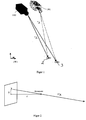
- die Darstellung einer Kamera in einer unbekannten Position {B}, welche aus einer kalibrierten, bekannten Position {A} translatorisch in die unkalibrierte Position {B} versetzt worden ist und
Figur 2- die Abbildung einer Meßmarke im idealisierten Bild einer Lochkamera mit der gegebenen Brennweite f, wobei das idealisierte Bild einer Lochkamera der Berechnung zur Reintegration der verstellten Kamera zugrunde gelegt wird.
- Figure 1
- the representation of a camera in an unknown position {B}, which has been translated from a calibrated, known position {A} into the uncalibrated position {B} and
- Figure 2
- the representation of a measuring mark in the idealized image of a pinhole camera with the given focal length f, the idealized image of a pinhole camera being used as the basis for the calculation for reintegrating the adjusted camera.
Das erfindungsgemäße Verfahren zur Reintegration einer verstellten Kamera 1
wird in seinem Lösungsansatz durchgeführt anhand von weder im Weltkoordinatensystem
{W} noch im Kamerakoordinatensystem {K} vermessenen Fixpunkten:
Folglich ist die Transformation A / B T gesucht, welche die Vektoren B
wobei i=1....n die Anzahl der Messmarken bedeutet mit:

where i = 1 .... n means the number of measuring marks with:
Dabei sind die A , B λ i die nicht bekannten Längen der Vektoren A,B
Ist der Arbeitsabstand der Kamera zum Objekt relativ zum Versatz groß, wenn
also der Arbeitsabstand mehrere Meter zum Versatz von einigen Millimetern
beträgt, so gilt:
Mit den normierten Abbildungsstrahlen kann ein nichtlineares Gleichungssystem nach der Gleichung 4 bestimmt werden, welches mit Standardverfahren, wie Linearisierung nach Newton und Ausgleichrechnung, mit z.B. SVD- Zerlegung, zu lösen ist.A nonlinear system of equations can be used with the standardized imaging beams can be determined according to equation 4, which with standard methods, such as Linearization according to Newton and compensation calculation, with e.g. SVD decomposition, too solve is.
Die nachfolgende Tabelle zeigt den resultierenden Fehler bei der
Positionserkennung nach Reintegration einer Kamera in ein reales System bei
einem Arbeitsabstand der Kamera vom Werkstück bzw. von der Meßmarke von
ungefähr 3 Meter:
Fehler in der Positionserfassung nach Reintegration einer Kamera Position detection error after reintegrating a camera
Die Tabelle zeigt, mit welchem zusätzlichem Fehler nach einem Stoß gegen die Kamera mit Reintegration zu rechnen ist.The table shows the additional error after an impact against the Reintegration camera is to be expected.
Der Gegenstand der Erfindung ist insbesondere in der automatisierten Fertigung von z.B. Fahrzeugkarossen zur Erkennung der Positionserkennung des Werkstückes, auf dem Gebiet der Kalibrierung von autonomen mobilen Systemen mit Kameras, insbesondere mit CCD-Sensoren, einsetzbar, um eine digitale Kamera, welche aus einer kalibrierten Position in eine unkalibrierte Position versetzt worden ist, zum Beispiel durch einen Schlag oder Stoß, wieder in das Bildverarbeitungssystem der Positionserkennung mit definiertem Koordinatensystem zu reintegrieren. Von besonderem Vorteil ist dabei, dass die verstellte Kamera nicht nochmals durch Kalibriertafeln neu kalibriert oder durch einen Theodoliten neu vermessen werden muß.The object of the invention is particularly in automated production from e.g. Vehicle bodies for detecting the position detection of the Workpiece, in the field of calibration of autonomous mobile systems with cameras, especially with CCD sensors, can be used to create a digital Camera moving from a calibrated position to an uncalibrated position has been relocated, for example by a blow or impact, back into the Image processing system for position detection with a defined coordinate system to reintegrate. It is particularly advantageous that the adjusted Do not recalibrate the camera again using calibration boards or one Theodolites must be measured again.
Claims (5)
dadurch gekennzeichnet, daß zur Herstellung des Zusammenhangs zwischen Weltkoordinatensystem ({W}) und Kamerakoordinatensystem ({K}) mindestens zwei nicht vermessene, in keinem der beiden Koordinatensysteme bekannte Messmarken (2,3) als Fixpunkt in jedes Kamerabild einer jeden Kamera (1) eingebracht werden, so daß Vektoren ( B
characterized in that, in order to establish the relationship between the world coordinate system ({W}) and the camera coordinate system ({K}), at least two measurement marks (2, 3) which have not been measured and are not known in either of the two coordinate systems are used as a fixed point in each camera image of each camera (1) be introduced so that vectors ( B

Applications Claiming Priority (2)
| Application Number | Priority Date | Filing Date | Title |
|---|---|---|---|
| DE10115149A DE10115149B4 (en) | 2001-03-27 | 2001-03-27 | Reintegration of a digital camera into an image processing system which has been moved from a calibrated position to an uncalibrated position |
| DE10115149 | 2001-03-27 |
Publications (3)
| Publication Number | Publication Date |
|---|---|
| EP1245344A2 true EP1245344A2 (en) | 2002-10-02 |
| EP1245344A3 EP1245344A3 (en) | 2006-03-08 |
| EP1245344B1 EP1245344B1 (en) | 2009-11-18 |
Family
ID=7679290
Family Applications (1)
| Application Number | Title | Priority Date | Filing Date |
|---|---|---|---|
| EP02003694A Expired - Lifetime EP1245344B1 (en) | 2001-03-27 | 2002-02-19 | Reintegration of a digital camera in an image processing system which is deplaced from a calibrated position in a non-calibrated position |
Country Status (3)
| Country | Link |
|---|---|
| EP (1) | EP1245344B1 (en) |
| AT (1) | ATE448916T1 (en) |
| DE (2) | DE10115149B4 (en) |
Cited By (3)
| Publication number | Priority date | Publication date | Assignee | Title |
|---|---|---|---|---|
| DE102005007536A1 (en) * | 2005-02-17 | 2007-01-04 | Isra Vision Systems Ag | Method for calibrating a measuring system |
| CN103471564A (en) * | 2013-04-19 | 2013-12-25 | 北京卫星环境工程研究所 | Multi-system measurement datum integrated transformation standard |
| CN106123798A (en) * | 2016-03-31 | 2016-11-16 | 北京北科天绘科技有限公司 | A kind of digital photography laser scanning device |
Families Citing this family (1)
| Publication number | Priority date | Publication date | Assignee | Title |
|---|---|---|---|---|
| DE102007008598A1 (en) * | 2007-02-19 | 2008-08-21 | Fraunhofer-Gesellschaft zur Förderung der angewandten Forschung e.V. | Automatic programming of robots to weld stapled profiles onto micropanels using digital image capture |
Citations (5)
| Publication number | Priority date | Publication date | Assignee | Title |
|---|---|---|---|---|
| DE19502459A1 (en) | 1995-01-28 | 1996-08-01 | Wolf Henning | Three dimensional optical measurement of surface of objects |
| EP0763406A1 (en) | 1995-09-15 | 1997-03-19 | ISRA Systemtechnik GmbH | Method of determination of the spatial position of an object |
| EP0700506B1 (en) | 1993-05-24 | 1998-04-08 | Metronor As | Method for geometry measurement |
| US6101455A (en) | 1998-05-14 | 2000-08-08 | Davis; Michael S. | Automatic calibration of cameras and structured light sources |
| DE10016963A1 (en) | 2000-04-06 | 2001-10-25 | Vmt Vision Machine Technic Gmb | Method for determining the position of a workpiece in 3D space |
Family Cites Families (1)
| Publication number | Priority date | Publication date | Assignee | Title |
|---|---|---|---|---|
| DE6940951U (en) * | 1969-10-20 | 1970-03-19 | Globus Teppich Fabrik Walter P | SQUEEGEE FOR APPLYING THE PVC DRIVE FOAM OD. DGL. EXISTING BACK STRENGTHENING OF PARTICULAR TUFTED CARPETS |
-
2001
- 2001-03-27 DE DE10115149A patent/DE10115149B4/en not_active Expired - Lifetime
-
2002
- 2002-02-19 DE DE50213999T patent/DE50213999D1/en not_active Expired - Lifetime
- 2002-02-19 EP EP02003694A patent/EP1245344B1/en not_active Expired - Lifetime
- 2002-02-19 AT AT02003694T patent/ATE448916T1/en not_active IP Right Cessation
Patent Citations (6)
| Publication number | Priority date | Publication date | Assignee | Title |
|---|---|---|---|---|
| EP0700506B1 (en) | 1993-05-24 | 1998-04-08 | Metronor As | Method for geometry measurement |
| DE69409513T2 (en) | 1993-05-24 | 1998-10-15 | Metronor As | METHOD FOR GEOMETRIC MEASUREMENT |
| DE19502459A1 (en) | 1995-01-28 | 1996-08-01 | Wolf Henning | Three dimensional optical measurement of surface of objects |
| EP0763406A1 (en) | 1995-09-15 | 1997-03-19 | ISRA Systemtechnik GmbH | Method of determination of the spatial position of an object |
| US6101455A (en) | 1998-05-14 | 2000-08-08 | Davis; Michael S. | Automatic calibration of cameras and structured light sources |
| DE10016963A1 (en) | 2000-04-06 | 2001-10-25 | Vmt Vision Machine Technic Gmb | Method for determining the position of a workpiece in 3D space |
Non-Patent Citations (8)
Cited By (6)
| Publication number | Priority date | Publication date | Assignee | Title |
|---|---|---|---|---|
| DE102005007536A1 (en) * | 2005-02-17 | 2007-01-04 | Isra Vision Systems Ag | Method for calibrating a measuring system |
| US8520067B2 (en) | 2005-02-17 | 2013-08-27 | Isra Vision Ag | Method for calibrating a measuring system |
| CN103471564A (en) * | 2013-04-19 | 2013-12-25 | 北京卫星环境工程研究所 | Multi-system measurement datum integrated transformation standard |
| CN103471564B (en) * | 2013-04-19 | 2015-05-13 | 北京卫星环境工程研究所 | Multi-system measurement datum integrated transformation standard |
| CN106123798A (en) * | 2016-03-31 | 2016-11-16 | 北京北科天绘科技有限公司 | A kind of digital photography laser scanning device |
| CN106123798B (en) * | 2016-03-31 | 2019-01-08 | 北京北科天绘科技有限公司 | A kind of digital photography laser scanning device |
Also Published As
| Publication number | Publication date |
|---|---|
| DE50213999D1 (en) | 2009-12-31 |
| DE10115149A1 (en) | 2002-10-10 |
| DE10115149B4 (en) | 2004-07-29 |
| EP1245344B1 (en) | 2009-11-18 |
| ATE448916T1 (en) | 2009-12-15 |
| EP1245344A3 (en) | 2006-03-08 |
Similar Documents
| Publication | Publication Date | Title |
|---|---|---|
| EP1848961B1 (en) | Method for calibrating a measuring system | |
| DE102016114337B4 (en) | SYSTEM AND METHOD FOR CONNECTING COORDINATE SPACES MACHINES LIKE ASSEMBLY FIXED IN AN ENVIRONMENT | |
| DE112010005008B4 (en) | System and method for determining camera calibration in runtime | |
| EP2603767B1 (en) | Method for calibrating a measurement system and device for carrying out the method | |
| EP1342051B1 (en) | Calibration of a measuring sensor on a coordinate measuring machine with a ball, whose center is known | |
| DE69937819T2 (en) | Optical determination of the relative positions of bodies in a room | |
| EP2249580B1 (en) | Method for calibrating the image of a camera | |
| DE69819027T2 (en) | 3D inspection of electronic pins with an optical element, which is arranged on the top of a transparent marker plate | |
| DE112013004851T5 (en) | Calibration method and calibration device | |
| WO2005075936A1 (en) | Method for determining the position of an object in a space | |
| DE112007001977T5 (en) | Method for generating three-dimensional model data and device for generating three-dimensional model data | |
| DE102016118620A1 (en) | Measuring system and measuring method | |
| DE10153049B4 (en) | 3D coordination system | |
| DE102021209178A1 (en) | Method and device for determining relative poses and for calibration in a coordinate measuring machine or robot | |
| EP0763406A1 (en) | Method of determination of the spatial position of an object | |
| WO2005031647A1 (en) | Method and device for contactless optical determination of the 3-d position of an object | |
| EP4094897B1 (en) | Hand-eye calibration of camera-guided devices | |
| EP1143221B1 (en) | Method for determining the position of a coordinate system of an object in a 3D space | |
| DE102017126495B4 (en) | Calibration of a stationary camera system for position detection of a mobile robot | |
| DE10048096A1 (en) | Swivel unit has optical sensor calibration sensor creates coordinate transformations | |
| EP1245344A2 (en) | Reintegration of a digital camera in an image processing system which is deplaced from a calibrated position in a non-calibrated position | |
| DE10118514B4 (en) | Method for operating point stabilization in contactless 3D position detection of an object to be measured by means of digital cameras | |
| DE102019110729A1 (en) | Method for aligning at least one calibration body and device for three-dimensional optical measurement of objects | |
| DE10340023B3 (en) | Self-calibration of camera system involves inserting matrices describing transformations into equation giving equation system linear in calibration parameters until it can be fully solved by computer | |
| EP1270410A2 (en) | Method for determining the state parameters of a rigid body in space by using a videometer |
Legal Events
| Date | Code | Title | Description |
|---|---|---|---|
| PUAI | Public reference made under article 153(3) epc to a published international application that has entered the european phase |
Free format text: ORIGINAL CODE: 0009012 |
|
| 17P | Request for examination filed |
Effective date: 20020226 |
|
| AK | Designated contracting states |
Kind code of ref document: A2 Designated state(s): AT BE CH CY DE DK ES FI FR GB GR IE IT LI LU MC NL PT SE TR |
|
| AX | Request for extension of the european patent |
Free format text: AL;LT;LV;MK;RO;SI |
|
| PUAL | Search report despatched |
Free format text: ORIGINAL CODE: 0009013 |
|
| AK | Designated contracting states |
Kind code of ref document: A3 Designated state(s): AT BE CH CY DE DK ES FI FR GB GR IE IT LI LU MC NL PT SE TR |
|
| AX | Request for extension of the european patent |
Extension state: AL LT LV MK RO SI |
|
| AKX | Designation fees paid |
Designated state(s): AT BE CH CY DE DK ES FI FR GB GR IE IT LI LU MC NL PT SE TR |
|
| GRAP | Despatch of communication of intention to grant a patent |
Free format text: ORIGINAL CODE: EPIDOSNIGR1 |
|
| GRAS | Grant fee paid |
Free format text: ORIGINAL CODE: EPIDOSNIGR3 |
|
| GRAA | (expected) grant |
Free format text: ORIGINAL CODE: 0009210 |
|
| AK | Designated contracting states |
Kind code of ref document: B1 Designated state(s): AT BE CH CY DE DK ES FI FR GB GR IE IT LI LU MC NL PT SE TR |
|
| REG | Reference to a national code |
Ref country code: GB Ref legal event code: FG4D Free format text: NOT ENGLISH |
|
| REG | Reference to a national code |
Ref country code: CH Ref legal event code: EP |
|
| REG | Reference to a national code |
Ref country code: IE Ref legal event code: FG4D |
|
| REF | Corresponds to: |
Ref document number: 50213999 Country of ref document: DE Date of ref document: 20091231 Kind code of ref document: P |
|
| REG | Reference to a national code |
Ref country code: NL Ref legal event code: VDEP Effective date: 20091118 |
|
| PG25 | Lapsed in a contracting state [announced via postgrant information from national office to epo] |
Ref country code: FI Free format text: LAPSE BECAUSE OF FAILURE TO SUBMIT A TRANSLATION OF THE DESCRIPTION OR TO PAY THE FEE WITHIN THE PRESCRIBED TIME-LIMIT Effective date: 20091118 Ref country code: ES Free format text: LAPSE BECAUSE OF FAILURE TO SUBMIT A TRANSLATION OF THE DESCRIPTION OR TO PAY THE FEE WITHIN THE PRESCRIBED TIME-LIMIT Effective date: 20100228 Ref country code: PT Free format text: LAPSE BECAUSE OF FAILURE TO SUBMIT A TRANSLATION OF THE DESCRIPTION OR TO PAY THE FEE WITHIN THE PRESCRIBED TIME-LIMIT Effective date: 20100318 Ref country code: SE Free format text: LAPSE BECAUSE OF FAILURE TO SUBMIT A TRANSLATION OF THE DESCRIPTION OR TO PAY THE FEE WITHIN THE PRESCRIBED TIME-LIMIT Effective date: 20091118 |
|
| PG25 | Lapsed in a contracting state [announced via postgrant information from national office to epo] |
Ref country code: CY Free format text: LAPSE BECAUSE OF FAILURE TO SUBMIT A TRANSLATION OF THE DESCRIPTION OR TO PAY THE FEE WITHIN THE PRESCRIBED TIME-LIMIT Effective date: 20091118 |
|
| REG | Reference to a national code |
Ref country code: IE Ref legal event code: FD4D |
|
| RAP2 | Party data changed (patent owner data changed or rights of a patent transferred) |
Owner name: VMT BILDVERARBEITUNGSSYSTEME GMBH |
|
| PG25 | Lapsed in a contracting state [announced via postgrant information from national office to epo] |
Ref country code: DK Free format text: LAPSE BECAUSE OF FAILURE TO SUBMIT A TRANSLATION OF THE DESCRIPTION OR TO PAY THE FEE WITHIN THE PRESCRIBED TIME-LIMIT Effective date: 20091118 Ref country code: IE Free format text: LAPSE BECAUSE OF FAILURE TO SUBMIT A TRANSLATION OF THE DESCRIPTION OR TO PAY THE FEE WITHIN THE PRESCRIBED TIME-LIMIT Effective date: 20091118 Ref country code: NL Free format text: LAPSE BECAUSE OF FAILURE TO SUBMIT A TRANSLATION OF THE DESCRIPTION OR TO PAY THE FEE WITHIN THE PRESCRIBED TIME-LIMIT Effective date: 20091118 |
|
| BERE | Be: lapsed |
Owner name: VMT BILDVERARBEITUNGSSYSTEME G.M.B.H. Effective date: 20100228 Owner name: TECMEDIC G.M.B.H. Effective date: 20100228 |
|
| PLBI | Opposition filed |
Free format text: ORIGINAL CODE: 0009260 |
|
| PLAX | Notice of opposition and request to file observation + time limit sent |
Free format text: ORIGINAL CODE: EPIDOSNOBS2 |
|
| REG | Reference to a national code |
Ref country code: CH Ref legal event code: PL |
|
| 26 | Opposition filed |
Opponent name: ISRA VISION SYSTEMS AG Effective date: 20100817 |
|
| PG25 | Lapsed in a contracting state [announced via postgrant information from national office to epo] |
Ref country code: LI Free format text: LAPSE BECAUSE OF NON-PAYMENT OF DUE FEES Effective date: 20100228 Ref country code: MC Free format text: LAPSE BECAUSE OF NON-PAYMENT OF DUE FEES Effective date: 20100301 Ref country code: CH Free format text: LAPSE BECAUSE OF NON-PAYMENT OF DUE FEES Effective date: 20100228 Ref country code: GR Free format text: LAPSE BECAUSE OF FAILURE TO SUBMIT A TRANSLATION OF THE DESCRIPTION OR TO PAY THE FEE WITHIN THE PRESCRIBED TIME-LIMIT Effective date: 20100219 |
|
| PLAF | Information modified related to communication of a notice of opposition and request to file observations + time limit |
Free format text: ORIGINAL CODE: EPIDOSCOBS2 |
|
| PG25 | Lapsed in a contracting state [announced via postgrant information from national office to epo] |
Ref country code: BE Free format text: LAPSE BECAUSE OF NON-PAYMENT OF DUE FEES Effective date: 20100228 |
|
| PG25 | Lapsed in a contracting state [announced via postgrant information from national office to epo] |
Ref country code: IT Free format text: LAPSE BECAUSE OF FAILURE TO SUBMIT A TRANSLATION OF THE DESCRIPTION OR TO PAY THE FEE WITHIN THE PRESCRIBED TIME-LIMIT Effective date: 20091118 |
|
| PLBB | Reply of patent proprietor to notice(s) of opposition received |
Free format text: ORIGINAL CODE: EPIDOSNOBS3 |
|
| PG25 | Lapsed in a contracting state [announced via postgrant information from national office to epo] |
Ref country code: AT Free format text: LAPSE BECAUSE OF NON-PAYMENT OF DUE FEES Effective date: 20100219 |
|
| PG25 | Lapsed in a contracting state [announced via postgrant information from national office to epo] |
Ref country code: LU Free format text: LAPSE BECAUSE OF NON-PAYMENT OF DUE FEES Effective date: 20100219 |
|
| PG25 | Lapsed in a contracting state [announced via postgrant information from national office to epo] |
Ref country code: TR Free format text: LAPSE BECAUSE OF FAILURE TO SUBMIT A TRANSLATION OF THE DESCRIPTION OR TO PAY THE FEE WITHIN THE PRESCRIBED TIME-LIMIT Effective date: 20091118 |
|
| RAP2 | Party data changed (patent owner data changed or rights of a patent transferred) |
Owner name: VMT VISION MACHINE TECHNIC BILDVERARBEITUNGSSYSTEM |
|
| PLBP | Opposition withdrawn |
Free format text: ORIGINAL CODE: 0009264 |
|
| PLBD | Termination of opposition procedure: decision despatched |
Free format text: ORIGINAL CODE: EPIDOSNOPC1 |
|
| PLBM | Termination of opposition procedure: date of legal effect published |
Free format text: ORIGINAL CODE: 0009276 |
|
| STAA | Information on the status of an ep patent application or granted ep patent |
Free format text: STATUS: OPPOSITION PROCEDURE CLOSED |
|
| 27C | Opposition proceedings terminated |
Effective date: 20130317 |
|
| REG | Reference to a national code |
Ref country code: FR Ref legal event code: PLFP Year of fee payment: 15 |
|
| REG | Reference to a national code |
Ref country code: FR Ref legal event code: PLFP Year of fee payment: 16 |
|
| REG | Reference to a national code |
Ref country code: FR Ref legal event code: PLFP Year of fee payment: 17 |
|
| PGFP | Annual fee paid to national office [announced via postgrant information from national office to epo] |
Ref country code: FR Payment date: 20210217 Year of fee payment: 20 |
|
| PGFP | Annual fee paid to national office [announced via postgrant information from national office to epo] |
Ref country code: DE Payment date: 20210125 Year of fee payment: 20 Ref country code: GB Payment date: 20210222 Year of fee payment: 20 |
|
| REG | Reference to a national code |
Ref country code: DE Ref legal event code: R071 Ref document number: 50213999 Country of ref document: DE |
|
| REG | Reference to a national code |
Ref country code: GB Ref legal event code: PE20 Expiry date: 20220218 |
|
| PG25 | Lapsed in a contracting state [announced via postgrant information from national office to epo] |
Ref country code: GB Free format text: LAPSE BECAUSE OF EXPIRATION OF PROTECTION Effective date: 20220218 |