EP1245305A2 - Press die for molding sipe blade and method for making the press die - Google Patents
Press die for molding sipe blade and method for making the press die Download PDFInfo
- Publication number
- EP1245305A2 EP1245305A2 EP02005034A EP02005034A EP1245305A2 EP 1245305 A2 EP1245305 A2 EP 1245305A2 EP 02005034 A EP02005034 A EP 02005034A EP 02005034 A EP02005034 A EP 02005034A EP 1245305 A2 EP1245305 A2 EP 1245305A2
- Authority
- EP
- European Patent Office
- Prior art keywords
- shape
- sipe blade
- press die
- molding
- mold
- Prior art date
- Legal status (The legal status is an assumption and is not a legal conclusion. Google has not performed a legal analysis and makes no representation as to the accuracy of the status listed.)
- Granted
Links
Images


Classifications
-
- B—PERFORMING OPERATIONS; TRANSPORTING
- B21—MECHANICAL METAL-WORKING WITHOUT ESSENTIALLY REMOVING MATERIAL; PUNCHING METAL
- B21D—WORKING OR PROCESSING OF SHEET METAL OR METAL TUBES, RODS OR PROFILES WITHOUT ESSENTIALLY REMOVING MATERIAL; PUNCHING METAL
- B21D37/00—Tools as parts of machines covered by this subclass
- B21D37/20—Making tools by operations not covered by a single other subclass
-
- B—PERFORMING OPERATIONS; TRANSPORTING
- B29—WORKING OF PLASTICS; WORKING OF SUBSTANCES IN A PLASTIC STATE IN GENERAL
- B29D—PRODUCING PARTICULAR ARTICLES FROM PLASTICS OR FROM SUBSTANCES IN A PLASTIC STATE
- B29D30/00—Producing pneumatic or solid tyres or parts thereof
- B29D30/06—Pneumatic tyres or parts thereof (e.g. produced by casting, moulding, compression moulding, injection moulding, centrifugal casting)
- B29D30/0601—Vulcanising tyres; Vulcanising presses for tyres
- B29D30/0606—Vulcanising moulds not integral with vulcanising presses
-
- B—PERFORMING OPERATIONS; TRANSPORTING
- B60—VEHICLES IN GENERAL
- B60C—VEHICLE TYRES; TYRE INFLATION; TYRE CHANGING; CONNECTING VALVES TO INFLATABLE ELASTIC BODIES IN GENERAL; DEVICES OR ARRANGEMENTS RELATED TO TYRES
- B60C11/00—Tyre tread bands; Tread patterns; Anti-skid inserts
- B60C11/03—Tread patterns
- B60C11/12—Tread patterns characterised by the use of narrow slits or incisions, e.g. sipes
- B60C11/1204—Tread patterns characterised by the use of narrow slits or incisions, e.g. sipes with special shape of the sipe
- B60C11/1218—Three-dimensional shape with regard to depth and extending direction
-
- B—PERFORMING OPERATIONS; TRANSPORTING
- B60—VEHICLES IN GENERAL
- B60C—VEHICLE TYRES; TYRE INFLATION; TYRE CHANGING; CONNECTING VALVES TO INFLATABLE ELASTIC BODIES IN GENERAL; DEVICES OR ARRANGEMENTS RELATED TO TYRES
- B60C11/00—Tyre tread bands; Tread patterns; Anti-skid inserts
- B60C11/03—Tread patterns
- B60C11/12—Tread patterns characterised by the use of narrow slits or incisions, e.g. sipes
- B60C11/1272—Width of the sipe
- B60C11/1281—Width of the sipe different within the same sipe, i.e. enlarged width portion at sipe bottom or along its length
-
- B—PERFORMING OPERATIONS; TRANSPORTING
- B29—WORKING OF PLASTICS; WORKING OF SUBSTANCES IN A PLASTIC STATE IN GENERAL
- B29D—PRODUCING PARTICULAR ARTICLES FROM PLASTICS OR FROM SUBSTANCES IN A PLASTIC STATE
- B29D30/00—Producing pneumatic or solid tyres or parts thereof
- B29D30/06—Pneumatic tyres or parts thereof (e.g. produced by casting, moulding, compression moulding, injection moulding, centrifugal casting)
- B29D30/0601—Vulcanising tyres; Vulcanising presses for tyres
- B29D30/0606—Vulcanising moulds not integral with vulcanising presses
- B29D2030/0607—Constructional features of the moulds
- B29D2030/0613—Means, e.g. sipes or blade-like elements, for forming narrow recesses in the tyres, e.g. cuts or incisions for winter tyres
-
- B—PERFORMING OPERATIONS; TRANSPORTING
- B60—VEHICLES IN GENERAL
- B60C—VEHICLE TYRES; TYRE INFLATION; TYRE CHANGING; CONNECTING VALVES TO INFLATABLE ELASTIC BODIES IN GENERAL; DEVICES OR ARRANGEMENTS RELATED TO TYRES
- B60C11/00—Tyre tread bands; Tread patterns; Anti-skid inserts
- B60C11/03—Tread patterns
- B60C11/12—Tread patterns characterised by the use of narrow slits or incisions, e.g. sipes
- B60C11/1204—Tread patterns characterised by the use of narrow slits or incisions, e.g. sipes with special shape of the sipe
- B60C2011/1213—Tread patterns characterised by the use of narrow slits or incisions, e.g. sipes with special shape of the sipe sinusoidal or zigzag at the tread surface
Definitions
- the present invention relates to a press die for molding a sipe blade and a method for making the press die. More particularly, it relates to a press die for molding a sipe blade which can efficiently mold a sipe blade having a complicated shape such as three-dimensional shape and having excellent mechanical strength characteristics and which can reduce production cost due to its simple structure, and a method for simply and efficiently making a press die for molding a sipe blade having a complicated shape such as a three-dimensional shape by a casting method.
- Tire molds are difficult to make by a machining method because they have complicated designs with sharp dent-shaped corner portions or undercut shapes, and generally they are made by casting methods. Of these molds, many of them are made of aluminum alloys, cast irons or cast steels. This tendency is conspicuous, especially, when the design shapes of tires have many grooves of about 0.1-3.0 mm in width which are called "sipe" (specifically, studless tires, etc.) and these tires molds cannot be made by mechanical methods.
- machining method means molding methods other than those causing contraction in the molding, such as casting, and as examples thereof, mention may be made of various molding methods employed in conventional methods for making metal molds for molding two-dimensional shape sipe blades, such as wire electric discharge machining, NC machining which uses ball end mill, and additionally various methods which can directly mold the shape of metal molds, such as ultrasonic machining and electric discharge machining.
- wire electric discharge machining is employed because partial metal molds consisting of a pair of top and bottom molds can be obtained at a time.
- partial metal molds consisting of a pair of top and bottom molds are obtained by making one of the molds and then making a reversal mold thereof.
- sipes 104 which are thin grooves of about 0.1-3.0 mm in width are sometimes formed in addition to ribs and lugs to improve gripping force and drainage.
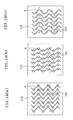
- the sipes 104 are in two-dimensional shape such as corrugated shape and zigzag shape at the ground contact face (profile face) for obtaining the effects to improve gripping force and drainage due to edge effect.
- a three-dimensional shape sipe 107b can improve block stiffness of tire 106 as compared with the conventional two-dimensional shape sipe 107a, the tire 106 does not undergo buckling even at driving and braking and can be further improved in gripping force.
- a sipe blade 111 (hereinafter sometimes referred to merely as “blade”) at a pattern 112 for casting a tire mold(hereinafter sometimes referred to merely as “pattern”) and then casting with a molten metal a blade 114 having finally a shape complementary to sipe 104 (see Fig. 36) to integrate with a metal mold 116 for molding a tire which is a reversal mold.
- a rubber mold 113 and a gypsum mold 115 are used.
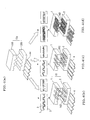
- the sipe blade 111 which is used for conventional method for producing a tire has been mainly produced by a method which comprises press molding a thin plate material 121 which is punched or laser cut (wire electric discharging cutting) using a press die 10a made by wire electric discharge machining.
- the sipe blade 111 shown in Fig. 39 (c) is consisting of a cross vent hole 122, a locking hole 123, a sipe formed portion 124, and a portion 125 which is cast in the metal mold for molding.
- a method for making a sipe blade of three-dimensional shape a method which comprises subjecting a press die for molding to a three-dimensional NC machining by a ball end mill, and press molding a thin raw material using the press die , but this method is high in cost and is not practical.
- a sipe blade of three-dimensional shape is required to be a combination of a plurality of those having basic shapes in which the number of the molded protrusive mountains is changed in the range of about 1-20 protrusive mountains. Therefore, according to conventional methods, metal mold or casting pattern must be made one by one, and this is troublesome.
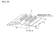
- the sipe blade 141 has a basic shape (primary shape) consisting of protruded shapes (protrusive dimple) 144 and dented shapes (dented dimple) 145 (Fig. 41 (a)), and additionally a molded shape (secondary shape) 143 which is larger than the basic shape in size is given to the whole sipe blade 141 (Fig. 41 (b)), position of disposition of the primary shapes at the top and bottom molds of the divided press die must be changed, and it is very difficult to make a press die for molding with taking these points into consideration.
- primary shape consisting of protruded shapes (protrusive dimple) 144 and dented shapes (dented dimple) 145
- secondary shape secondary shape
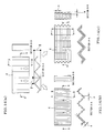
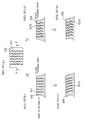
- the curving phenomenon occurs for the following reasons. That is, when the total length shrinkage caused by molding is considered by minimum unit of molding, the reason is as follows.
- the total length shrinkage 158 occurs non-uniformly. Therefore, the average total length shrinkage per one section becomes smaller than the case of two-dimensional molded shape which is the same in amplitude of molded protrusive shape (molded protrusive mountain or molded protrusive dimple). Therefore, when pitch and amplitude of the two-dimensional molded shape are set in correspondence to pitch and maximum amplitude of the three-dimensional molded shape such as protrusive dimple, the two-dimensional molded portion undergoes the greater total length shrinkage at the time of press molding to cause curved deformation as shown in Fig. 42 (a).
- the three-dimensional molded shape of the sipe blades used for conventional tire molds have the following problems.
- the sipe blade 111 which is disposed in the mold 116 and gives the corresponding sipe shape and a working tool interfere with each other (being obstructed by the dented and protruded shape of the sipe blade 111) to make it impossible to form the vent holes 161.
- a great bending load sometimes acts on the tire mold, especially, on the sipe blade at the time of molding of tire.
- This can be explained by a physical model corresponding to the bending of cantilever beam in material dynamics, and when the same material of sipe blade and plate thickness are used, the sipe blade having a molded shape which has a greater section modulus in respect to the axis of bending load can stand the greater bending load. Accordingly, by selecting a sectional shape greater in section modulus, a sipe blade stronger against the same bending moment can be obtained.
- the section modulus here means a material dynamic parameter relating to the sectional shape of a beam as described, for example, in Seike Seiichiro's Kogaku Kiso, "Zairyo Rikigaku (materials dynamics)” published from Kyoritsu Shuppan Co.
- both the sipe blades 111a and 111b produce a maximum bending stress at the section X against a bending load H.
- the two-dimensional molded sipe blade 111b is greater in section modulus at the section X than the planar sipe blade 111a, and, hence, the two-dimensional molded sipe blade 111b is smaller in the maximum bending stress generated at the section X.
- Fig. 49 (a) and Fig. 49 (b) in the case of the three-dimensional sipe blade 111c disclosed in JP-A-2001-1722, the similar phenomenon also occurs, and section modulus of the portion shown by a one-point chain line becomes smallest and, as a result, deformation or breakage is apt to occur at this portion.
- This sipe blade 111c gives satisfactory performance of the resulting tire, but the strength characteristics as a tire mold is not sufficient.
- the present invention has been made in view of the above problems, and the object of the present invention is to provide a press die for molding a sipe blade by which a sipe blade having a complicated shape such as three-dimensional shape and having excellent mechanical strength characteristics can be efficiently molded and which has a simple structure and can reduce the production cost, and a method for making simply and efficiently a press die for molding a sipe blade having a complicated shape such as three-dimensional shape by a casting method.
- the above object can be attained by the following procedures: basically, as a pattern used for the method for making a press die for molding a sipe blade utilizing a casting method, a metal mold having a shape which is reverse to the shape of the press die for molding sipe blade is made by machining or the like, and a portion of the press die for molding a sipe blade to which a load is applied by molding pressure in contact with a material for the sipe blade is allowed to have a shape (normal shape) corresponding to the desired shape of the sipe blade in order to impart the desired shape to the sipe blade, and, besides, a portion to which a load is not applied by the molding pressure without contacting with the material for the sipe blade is allowed to have a relief part which does not correspond to the desired shape of the sipe blade and dose not substantially contact with the sipe blade after molded.
- the present invention has been accomplished. That is, the following press die for molding a
- 1 a pair of partial molds (top mold); 1a: the portion to which a load is applied by molding pressure; 1b: the portion to which no load is applied by molding pressure; 2: a pair of partial molds (bottom mold); 2a: the portion to which a load is applied by molding pressure; 2b: the portion to which no load is applied by molding pressure; 3: material for sipe blade; 4: sipe blade; 4a: conventional sipe blade; 5: first relief part; 5a: groove; 6: a plurality of different three-dimensional shape; 7: a plurality of different three-dimensional shape; 8: crossing part; 9: second relief part; 10: press die for molding sipe blade; 10a: conventional press die for molding sipe blade; 11: pattern; 12: rubber mold; 13: mold for casting; 14: top mold; 15: molten metal; 16: casting (metal mold); 21: first shape; 22: first reversal mold; 23: first sipe blade replica; 23a: pro
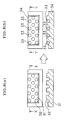
- a press die 10 for molding a sipe blade of the present invention is composed of a pair of the divided parts composing a press die 1 and 2, and a material 3 for the sipe blade is interposed and pressed between the pair of the divided parts composing a press die to mold a sipe blade 4 having a desired shape.
- the press die 10 is characterized in that portions 1a and 2a to which is applied a load caused by a molding pressure in contact with the material 3 for the sipe blade for giving a desired shape to the sipe blade 4 have the shapes corresponding to a desired shape of the sipe blade 4, and portions 1b and 2b to which is not applied a load caused by molding pressure without contacting with the material 3 for the sipe blade are provided with relief parts 5 (in Figs. 1, these have shapes of groove mentioned hereinafter) which do not correspond to the desired shape of the sipe blade 4 and do not substantially contact with the sipe blade after molded.
- do not substantially contact means that the relief parts do not function to give the desired shape to the sipe blade.
- a pair of the divided parts composing a press die 1 and 2 are made using machining method and casting method. Sintering method may be employed in place of the casting method.
- suitable examples are thin plates comprising high-strength materials such as metals having mechanical strength and durability capable of standing tire molding of many times, for example, SUS420J2, SUS631, etc. Thickness is usually about 0.1-2.0 mm though it depends on the width of sipe.
- the shape is not particularly limited, and sipe blades of nearly rectangle are generally used, and demand for those having complicated shapes such as three-dimensional dented and protruded shapes is enhanced.
- sipe blades of complicated shapes such as three-dimensional shapes can be efficiently molded, and it becomes possible to reduce the production cost of the mold per se with simple structure.
- sipe blade 400 having a three-dimensionally dented and protruded shape for example, as shown in Figs. 2, is to be made
- both the shapes of a pair of the divided parts composing a press die 100 and 200 between which a material 300 for sipe blade is interposed must correspond to the three-dimensional dented and protruded shape of the sipe blade 400.
- the metal mold having such a shape by machining method requires many steps for both the preparation of data of the shape and for machining time, and therefore the above method has hardly been employed.
- sipe blades having three-dimensional dented and protruded shapes have hardly been employed.
- each of the first relief part 5 which does not substantially contact with the sipe blade 4 has a depth equal to or greater than the height of the opposing portion which undergoes a load by molding pressure, and, besides, comprises a groove 5a having a bottom horizontal to the surface of the material 3 for the sipe blade.
- Figs. 1 show the case where in correspondence to the shape of the sipe blade 4, a pair of the divided parts composing a press die 1 and 2 have a three-dimensional dented and protruded shape, and the portions 1a and 2a to which is applied a load by molding pressure in contact with the material 3 for the sipe blade have protruded shapes and the portions to which is not applied a load by molding pressure without contacting with the material 3 for the sipe blade have dented shapes.
- the press die for molding sipe blade of the present invention can effectively exhibit the functions.
- the conventional press die 10a for molding sipe blade has a shape faithfully corresponding to the shape of the sipe blade 4 and has the different three-dimensional shapes 6 and 7 in such a state as the crossing part 8 being continuously integrated as shown in Fig. 3(b), but it is very difficult to make the mold 10(a) having the complicated shape.
- the shapes of a pair of the divided parts composing a press die do not necessarily correspond faithfully to a plurality of the different three-dimensional shapes of the sipe blade 4 which are continuously integrated at the crossing part of them; that is, the shapes of a pair of the divided parts composing a press die 1 and 2 may be discontinuous at the crossing part 8 with individually and independently maintaining the plurality of the three-dimensional shapes 6 and 7, and a second relief portion 9 which does not substantially contact with the material for sipe blade is formed at the crossing part 8.
- do not substantially contact means that the relief part does not function to give the desired shape to the sipe blade.
- the metal mold can be adapted to the molding of complicated three-dimensional shape utilizing the fitting (follow-up) characteristics of the sipe blade to the press die at the time of molding, and, hence, it is possible to omit the operation to define the shape of butting part (crossing part) of protrusive shapes (protrusive mountain shape or protrusive dimple) in molding a sipe blade having different three-dimensional shapes which has been troublesome and difficult. Furthermore, it is possible to shorten the time for working the pattern used in making the press die for molding sipe blade of the present invention, and the production cost of the press die per se can be reduced.
- Figs. 3 show the case of butting (crossing) of two different three-dimensional shapes, but this can be also suitably applied to the case of three or more different three-dimensional shapes and three or more butting parts (crossing parts).
- the press die 10 for molding sipe blade of the present invention may be such that in correspondence to the shape of the sipe blade, the shapes of divided parts composing a press die 1 and 2 are three-dimensional dented and protruded shapes having a primary molded shape and a secondary molded shape and have a plurality of protruded portions 162 to which a load is applied by the molding pressure in contact with the material 3 for sipe blade and are disposed so that a curved surface formed by connecting the apexes of the protruded portions 162 forms a primary molded shape (corrugated shape in Figs. 4).
- FIG. 4 (a) shows a conventional sipe blade 4a having a two-dimensional molded shape of only primary molded shape (corrugated shape)
- Fig. 4 (b) shows a sipe blade 4 having a three-dimensional molded shape to which secondary molded shape (protruded shape) is also imparted
- Fig. 4 (c) shows a sipe blade 4 having a three-dimensional molded shape to which secondary molded shape (dented shape) is also imparted
- Fig. 4 (d) shows a sipe blade 4 having a three-dimensional molded shape to which secondary molded shape (changes of plate thickness) is also imparted.
- Fig. 4 (b) shows a sipe blade 4 having a three-dimensional molded shape to which secondary molded shape (protruded shape) is also imparted
- Fig. 4 (c) shows a sipe blade 4 having a three-dimensional molded shape to which secondary molded shape (dented shape) is also imparted
- a sipe blade 4 having a three-dimensional molded shape to which secondary molded shape (shape of changes of plate thickness) is also imparted can be made at a time by one metal mold (a pair of the divided parts composing a press die 1 and 2).
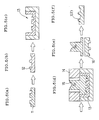
- the method for making a press die for molding a sipe blade according to the present invention is a method for making the press die 10 for molding a sipe blade as shown in Figs. 1 which comprises a pair of the divided parts composing a press die 1 and 2, between which a material 3 for sipe blade is interposed and pressed to mold the sipe blade 4 having the desired shape.
- the method for making a press die for molding a sipe blade of the present invention comprises forming patterns having a shape reverse to the shape of a pair of the divided parts composing a press die, and then forming from the patterns castings having a shape reverse to that of the patterns, and it is characterized in that a plurality of patterns having a shape reverse to the shape of the pair of the divided parts composing a press die are formed so that the portion to which a load is applied by molding pressure in contact with the material for the sipe blade have shapes corresponding to the desired shape of the sipe blade and the portions to which a load is not applied by molding pressure without contacting with the material for the sipe blade are provided with a first relief part which does not correspond to the desired shape of the sipe blade and does not substantially contact with the sipe blade after molded, and then castings having a shape reverse to the pattern are made, for example, by a casting method.
- the method will be explained below, referring to Figs. 5.
- a pattern 11 having a shape reverse to that of a pair of the divided parts composing a press die 1 is formed, for example, by machining method.
- a plurality of patterns 11 having a shape reverse to the shape of the pair of divided parts composing a press die 1 and 2 as shown in Fig. 5 (a) are formed so that, as shown in Figs. 1, the shape of the pair of divided parts composing a press die 1 and 2 which are final objectives is such that the portion 1a to which a load is applied by a molding pressure in contact with the material 3 for the sipe blade for giving a desired shape to the sipe blade 4 has the shape corresponding to the desired shape of the sipe blade 4, and the portion to which no load is applied by molding pressure without contacting with the material 3 for the sipe blade is provided with a first relief part 5.
- the pattern 11 is preferably made of materials which are easy in working and stable in size, such as gypsum, various resins (e.g., epoxy resins), metals and the like by machining method.
- materials which are easy in working and stable in size such as gypsum, various resins (e.g., epoxy resins), metals and the like by machining method.
- a rubber mold 12 having a shape reverse to the shape of the pattern is formed as shown in Fig. 5 (b).
- the rubber mold 12 is preferably formed of a silicone rubber or the like.
- a casting mold 13 having a shape reverse to the shape of the rubber mold is made from the rubber mold.
- material of the mold for casting 13 can be optionally selected depending on the casting alloy (mentioned later) cast in the press die, but a mold for casting made of ceramics can be used even when the casting alloy is an iron-based alloy of high casting temperatures.
- a molten metal 15 which is a molten casting alloy is cast in the fired mold for casting 13 (top mold 14).
- the casting alloys include high-strength materials such as tool steels (SK materials, SKD materials, etc.), beryllium copper alloys (BeA275C), etc. Above all, beryllium copper alloys are preferred. When beryllium copper alloys are used, if the material of the sipe blade is a steel material, dragging or seizing to the metal mold hardly occurs to make it easy to carry out the press molding operation of sipe blade.
- a casting 16 is recovered from the mold for casting and cut to the desired shape.
- the casting method there may be employed the above-mentioned ceramic mold method (Shaw process), and other precision casting methods (lost wax process, gypsum casting process), and die cast process. Furthermore, a sintering may be employed in place of the casting.
- the first relief part 5 which does not substantially contact with the sipe blade has a depth equal to or greater than the height of the protruded shape of the opposing portions of divided part composing a press die and, besides, comprises a groove 5a having a bottom horizontal to the surface of the material for the sipe blade as shown in Figs. 1, namely, the case where the pattern has a shape reverse to the shape thereof.
- Figs. 5 there is shown the case where the shape of the portions 1a and 2a to which a load is applied by the molding pressure in contact with the material 3 for the sipe blade is allowed to have a protruded shape and the shape of the portions to which a load is not applied by the molding pressure without contacting with the material 3 for the sipe blade is allowed to have dented shape so as to give a three-dimensional dented and protruded shape to a pair of divided parts composing a press die 1 and 2 in correspondence to the shape of the sipe blade 4 as shown in Figs. 1, namely, the case where the pattern has the shape reverse to the shape of a pair of divided parts composing a press die 1 and 2.
- the method for making a press die for molding sipe blade according to the present invention may be such that a plurality of protruded portions 162 to which a load is applied by the molding pressure in contact with the material 3 for the sipe blade are formed and simultaneously apexes of protruded portions 162 are disposed so that a curved face formed by connecting the apexes forms a primary molded shape (corrugated shape in Figs. 4) so as to give a three-dimensional dented and protruded shape to a pair of divided parts composing a press die 1 and 2 in correspondence to the shape of the sipe blade as shown in Figs. 4.
- the protruded shape portion protruded mountain portion or protruded dimple portion
- the dented shape portion dented valley portion or dented dimple portion
- the present invention makes it possible to efficiently mold a sipe blade of complicated shape such as a three-dimensional shape by utilizing to maximum the casting method which uses a pattern having a shape reverse to that of the press die for molding and, further, utilizing the fitting (follow-up) characteristics to the press die at the time of molding of the sipe blade.
- a plurality of pattern parts A-F divided into basic shapes commonly included in the plurality of the shapes are previously prepared and these pattern parts A-F may be optionally combined to construct the pattern 11 (Fig. 6 (a) shows the case where six kinds of pattern parts A-F of basic shapes are made).
- Fig. 6 (a) shows the case where six kinds of pattern parts A-F of basic shapes are made, and in this case, each of the plurality of the pattern parts may be made or they may be made by working one by one and each of them is duplicated, thereby making a plurality of the pattern parts.
- Fig. 6 (b) shows respectively the case of combining 3 pattern parts A, 3 pattern parts B, 1 pattern part C, 2 pattern parts D, 2 pattern parts E, and 1 pattern part F, thereby forming part 11
- Fig. 6 (c) shows the case of combining 5 pattern parts A, 5 pattern parts B, 1 pattern part C, 6 pattern parts D, 6 pattern parts E, and 1 pattern part F, thereby forming part 11.
- patterns can be efficiently made for making press die differing in the number of molded protruded portions. Moreover, by previously making pattern parts of various basic shapes, patterns can be rapidly completed only by combining (fabricating) them when necessary. Moreover, only the pattern is formed by such combination, and the press die per se can be made by the above-mentioned casting method using the pattern. Therefore, the press die for molding sipe blade can be allowed to have a continuous shape, and the problems in strength can also be solved, being different from conventional methods (where metal molds for molding are fabricated).
- the method for making the press die for molding sipe blade according to the present invention may be such that shapes of a plurality of the divided parts composing a press die 1 and 2 do not faithfully correspond to a plurality of different three-dimensional shapes of the sipe blade 4 which are continuously integrated, but shape of a pair of the divided parts composing a press die 1 and 2 are allowed to have a discontinuous shape individually and independently maintaining a plurality of three-dimensional shapes 6 and 7 of the sipe blade 4, and simultaneously a second relief part 9 which does not substantially contact with the material for sipe blade is formed at the crossing part 8, and patterns are formed corresponding thereto.
- a press die for molding sipe blade having primary molded shape (minimum dented and protruded shape) and additionally secondary molded shape (molded shape greater in wavelength than the primary molded shape) can be easily reproduced in one shape of metal mold.
- a first reversal mold having a shape reverse to the shape of the pattern is formed, a first sipe blade replica comprising a material easy in molding, such as sheet wax, is molded using the resulting reversal mold, a second shape is imparted to this first sipe blade replica using a given molding mold to mold a second sipe blade replica having both the first shape and the second shape, a pair of second reversal molds having a shape reverse to the shape of the second sipe blade replica are formed using the second sipe blade replica, and a casting having both the first shape and the second shape can be formed from the second reversal mold using a casting method. Further detailed explanation will be made below, referring to Figs. 7.
- a pattern 11 having a first shape 21 which is reverse to the primary molded shape of the objective final metal mold is made by a machining method.
- the pattern 11 is preferably made of materials easy in working and stable in size, such as gypsum, various resins (e.g., epoxy resins) and metals by a machining method.
- a first reversal mold 22 having the first shape is formed.
- the first reversal mold 22 is preferably made of, for example, gypsum, various resins (e.g., epoxy resins), etc.
- a first sipe blade replica 23 comprising a material easy in molding such as sheet wax and having the first molded shape is molded from the first reversal mold.
- This first sipe blade replica 23 has protruded shape 23a and dented shape 23b.
- the first sipe blade replica 23 preferably has the same thickness as of sipe blade, and as the materials thereof, mention may be made of, for example, thermosetting resins, sheet waxes, lead sheets, etc.
- a molding mold 24 for secondary molded shape using a molding mold 24 for secondary molded shape, a second shape corresponding to the secondary molded shape is imparted to the first sipe blade replica 23, and a second sipe blade replica 25 having both the first shape and the second shape is molded.
- the molding mold 24 for the secondary molded shape may be a gauge, and, besides, there is no need to use top and bottom molds and only one of them may be used.
- Preferred materials of the molding mold 24 for the secondary molded shape are, for example, gypsum, various resins (e.g., epoxy resins), etc.
- a resin e.g., epoxy resins
- a resin e.g., epoxy resins
- a rubber material is disposed on another side of the second sipe blade replica 25 on the backing material 26 to form a rubber mold 27 for a top mold.
- the second sipe blade replica 25 is removed to obtain a pair of second reversal molds having both the first shape and the second shape (rubber mold 27 for top mold and rubber mold 28 for bottom mold).
- a casting having both the first shape and the second shape can be formed from the second reversal mold (rubber mold 27 for top mold and rubber mold 28 for bottom mold) using a casting method.
- a press die having both the primary molded shape and the secondary molded shape can be simply made by the casting method.
- the second reversal molds 27, 28 (see Figs. 7), or combination thereof (pattern 31, etc.)
- a press die for molding a sipe blade having protruded shapes which correspond to dented shapes 32 of the pattern 31 and which are smaller in the number than the number of the dented shapes 32 is made, and the dented shape portion 32 of the pattern 31 is filled with a filler 33 so that the surface of the pattern 31 is in one plane with the dented shape portions 32, thereby forming a new pattern 34 and a casting having a shape reverse to the shape of this new pattern 34 can be formed from the new pattern 34.
- the filler 33 mention may be made of gypsum, various resins (e.g., epoxy resins), clay, etc.
- the time required for making the pattern can be shortened, and, besides, the new pattern 34 can be easily restored to the former pattern 31 by removing the filler 33 and can be used repeatedly. Thus, cost can be reduced.
- the sipe blade is sometimes distorted due to the difference in spreading length of the molded shapes at the time of press molding of the sipe blade.
- the drawn shape (peripheral shape) of the material of sipe blade (plane) can be set in the state of estimating the distorting portion, but requires experiential values by troublesome experiments and the like. Therefore, if possible, the peripheral shape may be trimmed (to cut) after press molding, but in case the peripheral shape is made by physical exterior force of cutting die (trimming die), it is very difficult to reproduce all of the surface shapes in the vicinity of the peripheral portion of the sipe blade by cutting die as reversal shapes. As other methods, it is considered to perform cutting by directional energy such as laser cutting, but in this case, there is a limit in irregular shape which can be followed up, and, besides, a great expense is necessary and this is not practical from the point of cost.
- the method for making trimming die for trimming a sipe blade according to the present invention has been accomplished in view of the above problems.
- the method for making a trimming die for trimming a sipe blade according to the present invention is a method for making a trimming die for trimming a sipe blade (trimming die) having a desired shape from a sipe blade rough mold (not shown) which is larger in size than the shape 41 to be trimmed (necessary peripheral shape) (see Fig. 9 (a)), characterized in that a third sipe blade replica 42 (see Fig. 9 (a)) larger than sipe blade and comprising a material easy in molding such as sheet wax is molded from the pattern 11 (see Figs.
- a pair of third reversal molds (rubber molds) 43 and 44 are made using said third sipe blade replica 42 and the backing material 26 (Fig. 9 (b) - 9 (e)); and a metal mold 45 for trimming (trimming die) (inner mold 45a, outer mold 45b) are formed using the third reversal molds 43 and 44 by a casting method (Fig. 9 (f)).
- the method for making a press die for molding sipe blade according to the present invention may be a method in which a press die 10 for molding sipe blade comprising a pair of the divided parts composing a press die 1 and 2, between which a material for sipe blade (not shown) is interposed and pressed to mold a sipe blade having a desired shape, is made by forming a pattern (not shown) having a shape reverse to the shape of the pair of the divided parts composing a press die 1 and 2 and then forming a casting (not shown) having a shape having a shape reverse to the pattern, characterized in that the portion of the pattern corresponding to the dented and protruded shape 163 in the secondary molded shape of the pair of the divided parts composing a press die 1 and 2 is formed by using a cutter mark in a chemical molding method, for example, chemical etching, a physical corrosion method or a machining method so that the pair of the metal molds 1 and 2 have a three-dimensional dented and protruded shape having a primary
- Fig. 10 (a) a secondary molded shape provided with the dented and protruded shape 163
- Fig. 10 (b) which is a sectional view taken along plane X of Fig. 10 (b)
- the sipe blade 4 shown in Fig. 10 (a) can be molded.
- FIGs. 11 are a sectional view showing the order of steps employing chemical molding method (chemical etching)).
- a basic pattern 164 of the primary molded shape and the reversal shape of the press die for molding sipe blade is formed (Fig. 11 (a)).
- materials of the pattern 164 are not limited as far as they can be chemically etched, and examples thereof are aluminum alloys, steel materials, copper alloys, etc.
- the area where the protruded shape of the dented and protruded shape on the surface of the pattern 164 is formed is subjected to masking with mask 165 (Fig. 11 (b)).
- the pattern 164 having the masking on the desired area of the surface is dipped in an etching solution 165a to remove by dissolution the area which is not masked (area which forms dented shape) (Fig. 11 (c)).
- the mask 165 is peeled off to obtain a pattern 166 on which a dented and protruded shape 163 is formed (Fig. 11 (d)).
- a rubber mold 167 having a shape reverse to the dented and protruded shape of the pattern 166 is formed (Fig. 11 (e)).
- a mold for casting 168 having a shape reverse to that of the rubber mold 167 is formed (Fig. 11 (f)).
- secondary molded shape e.g., complicated geometrical dented and protruded shape caused by the change in plate thickness
- primary molded shape e.g., corrugated shape
- the method for making a press die for molding sipe blade according to the present invention can be applied not only to the formation of the geometrical shape obtained by change in plate thickness, but also to the formation of shapes of natural objects such as leather, rocky and leaves patterns by the change in plate thickness.
- the method for making a press die for molding sipe blade according to the present invention may be such that so as to give a three-dimensional dented and protruded shape having a primary molded shape and a secondary molded shape provided with dented and protruded shape to the above-mentioned pair of divided parts composing a press die, a porous material is used as a material of the pattern (pattern material) (Fig.
- the above-mentioned press die for molding sipe blade and the sipe blade for the metal mold for molding tires which is produced by the production method according to the present invention are excellent in accuracy of size and have beautiful appearance even in the case of complicated shape such as three-dimensional shape.
- the sipe blade for tire mold according to the present invention is preferably such as having a conventional two-dimensional molded sipe shape of 1-5 mm in 1/2 pitch and 1-5 mm in amplitude of a primary molded shape (e.g., corrugated shape) as a basic shape, to which a two-dimensional or three-dimensional molded shape of smaller pitch of 0.05-2.5 mm in 1/2 pitch and 0.05-2.5 mm in amplitude of secondary molded shape is imparted.
- a primary molded shape e.g., corrugated shape
- sipe blade for tire mold of the present invention will be explained below.
- Specific Example 1 As Specific Example 1 of sipe blade for tire mold of the present invention, mention may be made of one which has a two-dimensionally definable primary molded shape, in which is present a two-dimensionally definable secondary molded shape which does not involve change in plate thickness and is smaller than the primary molded shape.
- the 1/2 pitch p and the amplitude w of the secondary molded shape are preferably set in the following ranges in respect to the 1/2 pitch P and the amplitude W of the primary molded shape. P/20 ⁇ p ⁇ P/2 W/20 ⁇ w ⁇ W/2
- the orientation of impartation of the secondary molded shape may be either the impartation of the secondary molded shape to the section A-A as shown in Fig. 14 (b) or the impartation of the secondary molded shape to the section B-B as shown in Fig. 14 (c), and, besides, the secondary molded shape may be imparted with inclination.
- the secondary molded shape it is preferred that it is not imparted to the cast-in portion for easy drawing of the sipe blade from the tire mold at the time of repairing of the tire mold.
- sipe blade for tire mold of the present invention mention may be made of one which has a two-dimensionally definable primary molded shape, in which is present a two-dimensionally definable secondary molded shape which involves change in plate thickness and is smaller than the primary molded shape.
- groove width wg, groove depth d and ungrooved section (ligament) wl in the secondary molded shape formed by the change in plate thickness are preferably set within the following ranges in respect to the 1/2 pitch P and the amplitude W of the primary molded shape and plate thickness (thickness of sipe blade) T. 0.05 ⁇ wg ⁇ [(P 2 +W 2 ) 1/2 ]/2 0.05 ⁇ wl ⁇ [(P 2 +W 2 ) 1/2 ]/2 0.05 ⁇ d ⁇ T/3
- the orientation of impartation of the secondary molded shape may be either the impartation of the secondary molded shape to the section C-C as shown in Fig. 16 (b) or the impartation of the secondary molded shape to the section D-D as shown in Fig. 16 (c), and, besides, the secondary molded shape may be imparted with inclination.
- the secondary molded shape may be disposed either by synchronization of various shapes or by shifting of phases as in (i)-(iv). In the case of imparting the secondary molded shape to the section D-D, it is preferred that it is not imparted to the cast-in portion for easy drawing of the sipe blade from the tire mold at the time of repairing of the tire mold.
- the sipe blade of Specific Example 2 is larger than that of Specific Example 1 in the proportion of the primary molded shape in the whole shape of the sipe blade, and, hence, the former sipe blade can be used in the similar manner to the conventional sipe blade of two-dimensional molded shape and can provide tires improved in performance without damaging flexural strength.
- a method of press molding by a bender a method of making primary and secondary molded shapes at a stretch by a press
- a method of previously imparting the secondary molded shape to the sipe blade material (plate material) by grinding, chemical etching, blasting or the like and press molding it by a metal mold for imparting the primary molded shape.
- the secondary molded shape is imparted to the sipe blade material by chemical etching or blasting, it is preferred to carry out the chemical etching or blasting with masking the portions which should not be made thin in thickness.
- sipe blade for tire mold of the present invention mention may be made of one which has a two-dimensionally definable primary molded shape, in which is present a two-dimensionally undefinable secondary molded shape which does not involve change in plate thickness and is smaller than the primary molded shape.
- widths we and wf and depth d of the secondary molded shape are preferably set within the following ranges in respect to the 1/2 pitch P and the amplitude W of the primary molded shape and plate thickness (thickness of the sipe blade) T. 2T ⁇ we, wf ⁇ P/2 2T ⁇ d ⁇ W/2
- the orientation of impartation of the secondary molded shape may be any of the impartation of the secondary molded shape (protruded shape) to the section E-E as shown in Fig. 18(b), the impartation of the secondary molded shape (dented shape) to the section E-E as shown in Fig. 18 (c) and the impartation of the secondary molded shape to the section F-F, and, besides, the secondary molded shape may be imparted to the inclined part (see Fig. 18 (d)).
- the secondary molded shape may be formed with changing the directions of dent and protrusion as shown in Figs. 18 (b) - 18 (d), but it is preferred that there are formed spaces between sipe blades 4 of various shapes shown in Figs. 19 (a) - 19 (c) in which vent holes 161 can be made in the case of making vent holes 161 in the tire mold.
- sipe blade for tire mold of the present invention mention may be made of one which has a two-dimensionally definable primary molded shape in which is present a two-dimensionally definable secondary molded shape which is formed by the change in plate thickness and is smaller than the primary molded shape.
- groove width lg and wg, groove depth d and ungrooved sections (ligament) 11 and wl in the secondary molded shape formed by the change in plate thickness are preferably set within the following ranges in respect to the 1/2 pitch P and the amplitude W of the primary molded shape and plate thickness (thickness of sipe blade) T. 0.05 ⁇ lg,wg ⁇ [(P 2 +W 2 ) 1/2 ]/2 0.05 ⁇ ll,w1 ⁇ [(P 2 +W 2 ) 1/2 ]/2 0.05 ⁇ d ⁇ T/3
- the orientation of impartation of the secondary molded shape may be either the impartation of the secondary molded shape (such changes in plate thickness as the groove widths lg, wg and the ungrooved sections (ligaments) 11, wl being opposed to each other) to the section G-G and the section H-H as shown in Fig. 20 (b) or the impartation of the secondary molded shape (such changes in plate thickness as the groove widths lg, wg and the ungrooved sections (ligaments) 11, wl being alternately opposed) to the section G-G and the section H-H as shown in Fig. 20 (c).
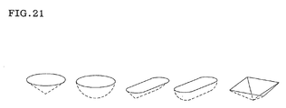
- the secondary molded shape may be not only the conical dented shape as shown in Figs. 20 (b) - 20 (c), but also the hemispherical dented shape, hemicylindrical dented shape, quadrangular pyramid dented shape (diamond cut shape), etc. as shown in Fig. 21.
- Molding of the sipe blade of Specific Example 4 may be carried out by embossing of the plate-like material before the formation of the primary molded shape or by chemical etching or sand blasting.
- press molding may be carried out at one time using a metal mold having combined primary molded shape and secondary molded shape which is made by casting method using the methods shown in Figs. 10 to Figs. 13.
- the tire mold which is formed using such a sipe blade can mold tires further improved in performances such as gripping power and the like.
- a pattern 51 for a press die having the shape as shown in Figs. 22 was prepared, and the press die for molding sipe blade was made through casting by ceramic mold method.
- a synthetic wood (chemiwood material) was used as a material of the pattern
- a silicone rubber (trade name: TSE350 manufactured by Toshiba Silicone Co., Ltd.) was used as a material of the rubber mold
- a ceramic casting mold material with ethyl silicate 40 as a binder was used as a material of the mold for casting (Shaw process mold for casting)
- beryllium copper alloy (BeA275C) was used as the casting alloy.
- Size of the pattern 51 was enlarged by 20/1000 equally in all axes taking the shrinkage caused by the casting into consideration. Furthermore, the size in Figs. 22 shows an aimed size of a completed final metal mold. As the casting method, general Shaw process was employed. In this way, a casting having a shape reverse to the shape of the pattern 51 could be made at a high accuracy.
- the resulting casting was subjected to a solution heat treatment of 800°C ⁇ 3 hr and then an aging treatment of 360°C ⁇ 3 hr, and this was used in the state of a hardness HRC of 40 as a press die for molding sipe blade.
- SUS304 stainless steel
- press molding was carried out under a pressure of 10 tons, and as a result, there could be molded a three-dimensional molded sipe blade having good bent shape which was a combined type of dented and protruded dimple shape zigzag disposition and triangular bent mountain shape without causing scoring and tearing. Distortion of the blade at the press molding was removed by correcting in drawn shape.
- the peripheral shape of the sipe blade after molded was 15 ⁇ 60 mm.
- a press die for molding was made in the same manner as in Example 1, using the pattern used in Example 1 in which the dented shape (dented dimple shape) of 5 rows in the central part and the dented portions (grooves) of the triangular bent mountain shape of 3 rows were filled with gypsum to make the surface in plane state.
- a press die for molding free from the bent mountain shape of the corresponding portion could be made, and the sipe blade could be molded without any problems (a sipe blade in which the shape of the corresponding portion was plane with bent shape on both sides could be molded).
- the peripheral shape of the sipe blade after molded was 15 ⁇ 60 mm.
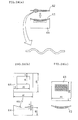
- a pattern 61 for a press die having the primary molded shape (the first shape) as shown in Figs. 23 was prepared, and from the resulting pattern 61, two reversal molds of epoxy resin was produced. Using them, a first replica 62 made of sheet wax having a thickness of 0.3 mm as shown in Fig. 24(a) was molded, and re-bent using a bender 64 for the secondary molded shape (the second shape) as shown in Fig. 24 (b) to mold a second replica 63 having both the primary molded shape and the secondary molded shape (the first shape and the second shape) as shown in Fig. 24 (c).
- sipe blade of the desired shape When an SUS304 material of 0.3 mm in plate thickness was press molded using the above press die, a sipe blade of the desired shape could be obtained. Furthermore, when a tire was molded using the resulting sipe blade, a sipe of the same shape as of the second replica 63 could be formed in the tire. Due to the casting shrinkage of the press die, the size of the sipe blade was smaller by about 20/1000 than the second replica 63.
- Two sets of press dies for molding having both the primary molded shape and the secondary molded shape were made in the same manner as in Example 3, and from each of them, inner mold 71 and outer mold 72 as shown in Fig. 25 were cut out by wire electrical discharge machining. They were re-fabricated to make top and bottom trimming dies 73 and 74. The clearance between the top mold 73 and the bottom mold 74 was set at not more than 0.01 mm.
- sipe blade molded in Example 3 (SUS304 material of 0.3 mm in plate thickness) was subjected to trimming process by the top and bottom molds 73 and 74 made above, a sipe blade having the peripheral shape same as the shape of the mold could be obtained.
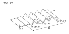
- a pattern 182 for top mold and a pattern 183 for bottom mold having the shape as shown in Figs. 26 (a) - 26 (b) and having a size of each part corresponding to the numerical value multiplied by 1/0.9800 were made by skiving a synthetic wood (chemiwood) by machining.
- the numerical values shown in Figs. 26 (a) - 26 (b) were aimed size after casting. The reason for the multiplication by 1/0.9800 was for enlargement of size in the pattern for supplementing the shrinkage of 20/1000.
- Figs. 26 (c) - 26 (d) are sectional views taken along the line I-I and the line J-J of Figs. 26 (a) - 26 (b), respectively.
- a press die for molding sipe blade (a bending mold having a shape reverse to the shape of the pattern 182 for top mold and the pattern 183 for bottom mold) was completed in the same manner as in Example 1.
- SUS304 stainless steel
- SUS304 stainless steel
- the peripheral shape of the sipe blade after molded was 18 ⁇ 30 mm.
- a pattern 182 for top mold and a pattern 183 for bottom mold having the shape as shown in Figs. 28 (a) - 26 (b) and having a size of each part corresponding to the shown numerical value multiplied by 1/0.9800 were made by skiving a synthetic wood (chemiwood) by machining.
- the numerical values shown in Figs. 28 (a) - 28 (b) were the size aimed at after casting. The reason for the multiplication by 1/0.9800 was for enlargement of size in the pattern for supplementing the shrinkage of 20/1000.
- Figs. 28 (c) - 28 (d) are sectional views taken along the line K-K and the line L-L of Figs. 28 (a) - 28 (b), respectively.
- a press die for molding sipe blade (a press die having a shape reverse to the shape of the pattern 182 for top mold and the pattern 183 for bottom mold) was completed in the same manner as in Example 1.
- SUS304 stainless steel
- SUS304 stainless steel
- the peripheral shape of the sipe blade after molded was 12.5 ⁇ 20 mm.
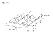
- a pattern 182 for top mold and a pattern 183 for bottom mold having the shape as shown in Figs. 30 (a) - 30 (b) and having a size of each part corresponding to the shown numerical value multiplied by 1/0.9800 were made by skiving a synthetic wood (chemiwood) by machining.
- the numerical values shown in Figs. 30 (a) - 30 (b) were the size aimed at after casting. The reason for the multiplication by 1/0.9800 was for enlargement of size in the pattern for supplementing the shrinkage of 20/1000.
- Figs. 30 (c) - 30 (d) are sectional views taken along the line M-M, the line N-N and the line O-O of Figs. 30 (a) - 30 (b), respectively.
- a press die for molding sipe blade (a press die having a shape reverse to the shape of the pattern 182 for top mold and the pattern 183 for bottom mold) was completed in the same manner as in Example 1.
- SUS304 stainless steel
- SUS304 stainless steel
- the peripheral shape of the sipe blade after molded was 14 ⁇ 20 mm.
- a pattern 182 for top mold and a pattern 183 for bottom mold having the shape as shown in Figs. 32 (a) - 32 (b) and having a size of each part corresponding to the shown numerical value multiplied by 1/0.9800 were made by skiving a synthetic wood (chemiwood) by machining.
- the numerical values shown in Figs. 32 (a) - 32 (b) were the size aimed at after casting. The reason for the multiplication by 1/0.9800 was for enlargement of size in the pattern for supplementing the shrinkage of 20/1000.
- Figs. 32 (a)- 32 (b) there are shown sectional views taken along the line S-S and the line T-T.
- Fig. 32 (c) is a sectional view taken along the line U-U of Figs. 32 (a) - 32 (b).
- Figs. 32 (d) - 32 (e) are enlarged views of the section H and the section I.
- a press die for molding sipe blade (a press die having a shape reverse to the shape of the pattern 182 for top mold and the pattern 183 for bottom mold) was completed in the same manner as in Example 1.
- SUS304 stainless steel
- SUS304 stainless steel
- the peripheral shape of the sipe blade after molded was 14 ⁇ 20 mm.
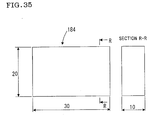
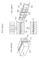
- a pattern 184 for changing of plate thickness (common use for top and bottom molds) having the shape as shown in Fig. 34 (a) and having a size of each part corresponding to the shown numerical value multiplied by 1/0.9800 was made by skiving a square material from an aluminum alloy material (material of JIS A5052) by machining and locally dissolving out the surface of the square material by chemical etching (a masking tape having openings of the corresponding design was applied to the surface of the square material, followed by etching with an aqueous hydrogen fluoride solution).
- Fig. 34 (a) a sectional view taken along the line P-P is shown.
- Fig. 34 (b) is an enlarged view of the section J.
- Fig. 34 (b) shows a sectional view taken along the line Q-Q.
- the engagement of the top and bottom molds of the press die was zigzag as shown in Fig. 34 (b), and the protruded portions of 0.6 mm ⁇ in diameter and 0.15 mm in height were engaged.
- a plane material used in pressing in Examples 5-7 was preliminarily molded under a pressure of 15 tons, and thereafter press molded by the press molds made in the above examples, and as a result, dented and protruded shape (protrusion 185 of the top mold and protrusion 186 of the bottom mold of about 0.05-0.10 mm at plate thickness level could be imparted to the sipe blades 4 of three-dimensional molded shape of Examples 5-7 at a pitch of 0.8 mm (namely, three-dimensional molded shape could be imparted).
- a pattern 184 for changing of plate thickness (common use for top and bottom molds) having the shape as shown in Fig. 35 was made by skiving from a material of G-1 foamed gypsum (water content 65%, foaming rate 50%, manufactured by Noritake Gypsum Co., Ltd.) in the state of free water being removed.
- the surface of this pattern 184 for changing of plate thickness (common use for top and bottom molds) was in such a state that innumerable foams of about 0.02-0.3 mm in diameter ⁇ were exposed.
- Fig. 35 shows a sectional view taken along the line R-R.
- the present invention provides a press die for molding sipe blade according to which a sipe blade having complicated shape such as three-dimensional shape and, besides, excellent mechanical strength characteristics can be efficiently molded, and, further, production cost can be reduced with a simple structure, and, further, provides a method for making a press die for molding sipe blade according to which a sipe blade having complicated shape such as three-dimensional shape can be simply and efficiently made by casting method.
- a press die for molding a sipe blade which can efficiently mold a sipe blade having a complicated shape such as three-dimensional shape and having excellent mechanical strength characteristics and which can reduce production cost due to its simple structure, and further provided is a method for simply and efficiently making a press die for molding a sipe blade having a complicated shape such as a three-dimensional shape by a casting method.
- the press die 10 for molding the sipe blade of the present invention is composed of a pair of the divided parts composing a press die 1 and 2, and a material 3 for the sipe blade is interposed and pressed between the pair of the divided parts composing a press die to mold a sipe blade 4 having a desired shape, and is characterized in that portions 1a and 2a to which is applied a load caused by a molding pressure in contact with the material 3 for the sipe blade for giving a desired shape to the sipe blade 4 have the shapes corresponding to a desired shape of the sipe blade 4, and portions 1b and 2b to which is not applied a load caused by molding pressure without contacting with the material 3 for the sipe blade are provided with first relief parts 5 which do not correspond to the desired shape of the sipe blade 4 and do not substantially contact with the sipe blade after molded.
Landscapes
- Engineering & Computer Science (AREA)
- Mechanical Engineering (AREA)
- Moulds For Moulding Plastics Or The Like (AREA)
- Tires In General (AREA)
Abstract
Description
The sipes 104 are in two-dimensional shape such as corrugated shape and zigzag shape at the ground contact face (profile face) for obtaining the effects to improve gripping force and drainage due to edge effect. Recently, for further improvement of tire performance, it is demanded that not only the profile face, but also the shape in the direction of diameter of tire have the similar two-dimensional shape (moreover, complicated curved faces such as three-dimensional shape), namely, it is demanded to make the shape of sipes to three-dimensional shape.
1: a pair of partial molds (top mold); 1a: the portion to which a load is applied by molding pressure; 1b: the portion to which no load is applied by molding pressure; 2: a pair of partial molds (bottom mold); 2a: the portion to which a load is applied by molding pressure; 2b: the portion to which no load is applied by molding pressure; 3: material for sipe blade; 4: sipe blade; 4a: conventional sipe blade; 5: first relief part; 5a: groove; 6: a plurality of different three-dimensional shape; 7: a plurality of different three-dimensional shape; 8: crossing part; 9: second relief part; 10: press die for molding sipe blade; 10a: conventional press die for molding sipe blade; 11: pattern; 12: rubber mold; 13: mold for casting; 14: top mold; 15: molten metal; 16: casting (metal mold); 21: first shape; 22: first reversal mold; 23: first sipe blade replica; 23a: protruded shape; 23b: dented shape; 24: molding mold for secondary molded shape; 25: second sipe blade replica; 26: backing material; 27: rubber mold for top mold; 28: rubber mold for bottom mold; 31: pattern, etc.; 32: dented shape; 33: filler; 34: new pattern; 41: shape to be trimmed; 42: third sipe blade replica; 43: third reversal mold; 44: third reversal mold; 45: metal mold for trimming (trimming die); 45a: inner mold; 45b: outer mold; 51: pattern; 61: pattern; 62: First replica; 63: second replica; 64: bending mold for secondary molded shape (second shape); 71: inner mold; 72: outer mold; 73: trimming die (top mold); 74: trimming die (bottom mold); 101: tire; 102: thick groove such as rib; 103: thick groove such as lug; 104: sipe; 106: tire; 107: sipe; 107a:conventional two-dimensional shape sipe; 107b: three-dimensional shape sipe; 111: sipe blade; 111a: plane sipe blade; 111b: two-dimensional molded sipe blade; 111c: three-dimensional molded sipe blade; 112: pattern for casting for molding tire; 113: rubber mold; 114: blade for tire mold; 115: gypsum casting; 116: tire mold; 116a: tire mold (top and bottom integral mold); 117: wire; 121: thin plate material; 122: cross vent hole; 123: locking hole; 124: sipe forming part; 125: cast in part; 131: divided press die; 132: divided press die ; 133: combined (fabricated) press die ; 134: combined (fabricated) press die ; 135: combined (fabricated) press die ; 141: sipe blade; 142: basic shape (primary shape); 143: larger molded shape (secondary shape); 144: protruded shape (protruded dimple); 145: dented shape (dented dimple); 151: originally supposed trimmed shape; 152: sipe blade of curved shape; 153: two-dimensional shape; 154: three-dimensional shape; 155: material of trimmed shape of two-dimensional shape sipe blade; 156: total shrinkage in length; 157: material of trimmed shape of three-dimensional shape sipe blade; 158: total shrinkage in length; 159: crank molded shape; 160: tire after molded; 161: vent hole; 162: protruded shape portion; 163: dented and protruded shape; 164: (basic) pattern; 165: mask; 165a: etching solution; 166: pattern with dented and protruded shape; 167: rubber mold; 168: mold for casting; 169: casting; 170: hot top; 171: product part; 172: material of pattern; 173: cutter mark; 174: pattern after worked; 175: rubber mold; 176: porous pattern; 180: projection corresponding to rib; 181: projection corresponding to lug; 182: pattern for top mold; 183: pattern for bottom mold; 184: pattern for changing of plate thickness; 185: top mold protrusion; 186: bottom mold protrusion; 100, 200: conventional pair of partial metal molds; 300: material for sipe blade; 400: sipe blade; A-F: pattern parts; G: direction of removal of metal mold; H: bending load.
Moreover, only the pattern is formed by such combination, and the press die per se can be made by the above-mentioned casting method using the pattern. Therefore, the press die for molding sipe blade can be allowed to have a continuous shape, and the problems in strength can also be solved, being different from conventional methods (where metal molds for molding are fabricated).
As Specific Example 1 of sipe blade for tire mold of the present invention, mention may be made of one which has a two-dimensionally definable primary molded shape, in which is present a two-dimensionally definable secondary molded shape which does not involve change in plate thickness and is smaller than the primary molded shape.
Distortion of the blade at the press molding was removed by correcting in drawn shape.
Claims (23)
- A press die for molding a sipe blade which comprises a pair of divided parts composing a press die between which a material of a sipe blade is interposed and pressed to mold a sipe blade having a desired shape, characterized in that
a portion of each of the pair of the divided parts composing a press die to which a load is applied by a molding pressure in contact with the material for the sipe blade has a shape corresponding to a desired shape of the sipe blade in order to impart the desired shape to the sipe blade, and the portion to which a load is not applied by the molding pressure without contacting with the material for the sipe blade has a relief part which dose not substantially contact with the sipe blade after molded. - A press die for molding a sipe blade according to claim 1, wherein the pair of the divided parts composing a press die are made using a machining method or a casting method.
- A press die for molding a sipe blade according to claim 1 or 2, wherein a first relief part which does not substantially contact with the sipe blade has a depth equal to or greater than the height of the opposing portions to which a load is applied by the molding pressure and which comprises a groove having a bottom horizontal to the surface of the material of the sipe blade.
- A press die for molding a sipe blade according to any one of claims 1 to 3, wherein the pair of the divided parts composing a press die have three-dimensional dented and protruded shape corresponding to the shape of the sipe blade, the portion of the metal molds to which a load is applied by the molding pressure due to contact with the material of the sipe blade has a protruded shape, and the portion to which a load is not applied by the molding pressure without contacting with the material for the sipe blade has a dented shape.
- A press die for molding a sipe blade according to claim 4, wherein the shapes of the pair of the divided parts composing a press die are discontinuous with individually and independently maintaining the plurality of the three-dimensional shapes, and a second relief portion is formed at the crossing part which does not substantially contact with the material for sipe blade.
- A press die for molding a sipe blade according to claim 4, wherein in correspondence to the shapes of the sipe blade, the shapes of a pair of divided parts composing a press die are three-dimensional dented and protruded shapes having a primary molded shape and a secondary molded shape and have a plurality of protruded shape portions to which a load is applied by the molding pressure in contact with the material for sipe blade and are disposed so that a curved face formed by connecting the apexes of the protruded shape portions forms a primary molded shape.
- A method for making a press die for molding a sipe blade comprising a pair of divided parts composing a press die between which a material of the sipe blade is interposed and pressed to mold a sipe blade having a desired shape by forming a pattern having a shape reverse to the shape of the pair of the divided parts composing a press die and then forming from the pattern a casting having a shape reverse to that of the pattern, characterized in that a plurality of patterns having a shape reverse to the shape of the pair of the divided parts composing a press die are formed so that the pair of the metal molds have such shape that the portion to which a load is applied by molding pressure in contact with the material for the sipe blade have shapes corresponding to the desired shape of the sipe blade and the portion to which a load is not applied by molding pressure without contacting with the material for the sipe blade is provided with a first relief part which does not correspond to the desired shape of the sipe blade and does not substantially contact with the sipe blade after molded, and then castings having shapes reverse to the patterns are formed.
- A method for making a press die for molding a sipe blade according to claim 7, wherein a plurality of the patterns having a shape reverse to the shape of the pair of the divided parts composing a press die are formed by a machining method and then the castings having the shape reverse to the patterns are formed by a casting method.
- A method for making a press die for molding a sipe blade according to claim 7 or 8, wherein the first relief part which does not substantially contact with the sipe blade comprises a groove having a depth equal to or greater than the height of the protruded shape of the opposing divided parts composing a press die and, besides, having a bottom horizontal to the surface of the material for the sipe blade.
- A method for making a press die for molding a sipe blade according to any one of claims 7 to 9, wherein the shape of the portions to which a load is applied by the molding pressure in contact with the material for the sipe blade is allowed to have a protruded shape and the shape of the portions to which a load is not applied by the molding pressure without contacting with the material for the sipe blade is allowed to have a dented shape so as to give a three-dimensional dented and protruded shape to a pair of divided parts composing a press die in correspondence to the shape of the sipe blade.
- A method for making a press die for molding a sipe blade according to claim 10, wherein a plurality of protruded portions to which a load is applied by the molding pressure in contact with the material for the sipe blade are formed and simultaneously apexes of the protruded portions are disposed so that a curved face formed by connecting the apexes forms the primary molded shape so as to give a three-dimensional dented and protruded shape to a pair of divided parts composing a press die in correspondence to the shape of the sipe blade.
- A method for making a press die for molding a sipe blade according to any one of claims 7 to 11, wherein a plurality of pattern parts divided into basic shapes commonly included in the plurality of the shapes of the sipe blade are previously prepared so that sipe blades having a plurality of shapes can be optionally provided, and these pattern parts are optionally combined to construct a pattern.
- A method for making a press die for molding a sipe blade according to any one of claims 7 to 11, wherein the pattern is formed so that the shapes of the pair of the divided parts composing a press die are discontinuous with individually and independently maintaining a plurality of the shapes, and a second relief part is formed at the crossing part which does not substantially contact with the material for sipe blade.
- A method for making a press die for molding a sipe blade according to any one of claims 7 to 13, wherein a first reversal mold having a first shape reverse to the shape of the pattern or combination thereof is formed, a first sipe blade replica comprising a material easy in molding, such as sheet wax, is molded using the resulting reversal mold using the resulting reversal mold, a second shape is imparted to this first sipe blade replica using a given mold to mold a second sipe blade replica having both the first shape and the second shape, a pair of second reversal molds having a shape reverse to the shape of the second sipe blade replica is formed using the second sipe blade replica, and a casting having both the first shape and the second shape is formed from the second reversal mold using a casting method.
- A method for making a press die for molding a sipe blade having less protruded shapes than the dented shapes of the pattern and/or the second reversal mold obtained in the intermediate stage in the method mentioned in any one of claims 7-14 using said pattern or said second reversal mold obtained in the intermediate stage in the method of any one of claims 7-14, or combination thereof (pattern, etc.), characterized in that the dented shape portion of the pattern and/or the second reversal mold is filled with a filler so that the surface of the dented shape portion is in one plane, thereby forming a new pattern, and a casting having a shape reverse to the shape of this new pattern is formed from the new pattern by a casting method.
- A method for making a metal mold for trimming a sipe blade (trimming die) having a given shape from a sipe blade rough mold which is larger in size than the sipe blade and formed by molding a material for sipe blade, characterized in that a third sipe blade replica larger than the sipe blade and comprising a material easy in molding such as sheet wax is molded from the pattern, the first reversal mold having the shape reverse to the shape of the new pattern or the mold for the secondary molded shape formed in the intermediate stage of the method mentioned in any one of claims 7 to 15, or combination thereof (reversal mold, etc.), a pair of third reversal molds are made using the third sipe blade replica, and a metal mold for trimming is formed using the third reversal mold by a casting method.
- A method for making a press die for molding a sipe blade comprising a pair of divided parts composing a press die between which a material of the sipe blade is interposed and pressed to mold a sipe blade having a desired shape by forming a pattern having a shape reverse to the shape of the pair of the divided parts composing a press die and then forming a casting having a shape reverse to the shape of the pattern, characterized in that the portion of the pattern corresponding to the dented and protruded shape in the secondary molded shape the pair of the divided parts composing a press die is formed by using a cutter mark in a chemical molding method, a physical corrosion method or a machining method so that the pair of the metal molds have a three-dimensional dented and protruded shape having a primary molded shape and a secondary molded shape provided with a dented and protruded shape.
- A method for making a press die for molding a sipe blade according to claim 17, wherein a chemical etching method is employed as the chemical molding method.
- A method for making a press die for molding a sipe blade comprising a pair of divided parts composing a press die between which a material of the sipe blade is interposed and pressed to mold a sipe blade having a desired shape by forming a pattern having a shape reverse to the shape of the pair of the divided parts composing a press die and then forming a casting having a shape reverse to the shape of the pattern, characterized in that the portion of the pattern corresponding to the dented and protruded shape in the secondary molded shape of the pair of the divided parts composing a press die is formed by using a porous material as a material of the pattern so that the pair of the metal molds have a three-dimensional dented and protruded shape having a primary molded shape and a secondary molded shape provided with a dented and protruded shape.
- A sipe blade for a tire mold, which is molded using a press die for molding sipe blade mentioned in any one of claims 1 to 6.
- A sipe blade for a tire mold, which is molded using a press die for molding sipe blade made by a method for making a press die for molding a sipe blade mentioned in any one of claims 7 to 15 and 17 to 19.
- A sipe blade for a tire mold according to claim 20 or 21, which has a 1/2 pitch of 1-5 mm and an amplitude of 1-5 mm of the primary molded shape and a 1/2 pitch of 0.05-2.5 mm and an amplitude of 0.05-2.5 mm of the secondary molded shape.
- A tire mold formed by using the sipe blade for tire mold mentioned in any one of claims 20 to 22.
Applications Claiming Priority (4)
| Application Number | Priority Date | Filing Date | Title |
|---|---|---|---|
| JP2001091447 | 2001-03-27 | ||
| JP2001091447 | 2001-03-27 | ||
| JP2001315662 | 2001-10-12 | ||
| JP2001315662A JP3811045B2 (en) | 2001-03-27 | 2001-10-12 | Sipe blade molding die and manufacturing method thereof |
Publications (3)
| Publication Number | Publication Date |
|---|---|
| EP1245305A2 true EP1245305A2 (en) | 2002-10-02 |
| EP1245305A3 EP1245305A3 (en) | 2004-04-07 |
| EP1245305B1 EP1245305B1 (en) | 2009-11-04 |
Family
ID=26612271
Family Applications (1)
| Application Number | Title | Priority Date | Filing Date |
|---|---|---|---|
| EP02005034A Expired - Lifetime EP1245305B1 (en) | 2001-03-27 | 2002-03-06 | Press die for molding sipe blade and method for making the press die |
Country Status (4)
| Country | Link |
|---|---|
| US (1) | US6792828B2 (en) |
| EP (1) | EP1245305B1 (en) |
| JP (1) | JP3811045B2 (en) |
| DE (1) | DE60234228D1 (en) |
Cited By (4)
| Publication number | Priority date | Publication date | Assignee | Title |
|---|---|---|---|---|
| WO2013011335A1 (en) * | 2011-07-19 | 2013-01-24 | Tauform Abroncsgyártó Kft. | Lamella for forming a sipe and a tyre provided by such a sipe, and a method for forming said lamella |
| EP2440416A4 (en) * | 2009-06-12 | 2013-10-30 | Michelin & Cie | PROGRESSIVE MOLDING ELEMENT FOR PNEUMATIC, PNEUMATIC AND PNEUMATIC TIRES FORMED THEREBY |
| CN105728573A (en) * | 2016-05-05 | 2016-07-06 | 太仓小小精密模具有限公司 | Production process of impact-resistant die |
| CN108883671A (en) * | 2016-04-06 | 2018-11-23 | 株式会社普利司通 | Tire model and tire |
Families Citing this family (54)
| Publication number | Priority date | Publication date | Assignee | Title |
|---|---|---|---|---|
| FR2826911A1 (en) * | 2001-07-09 | 2003-01-10 | Michelin Soc Tech | Motor vehicle tyre tread has circumferential ribs with stepped and angled transverse incisions |
| JP2005505456A (en) * | 2001-10-11 | 2005-02-24 | ソシエテ ド テクノロジー ミシュラン | Treads with incisions, and laminar forming these incisions |
| GB2405678B (en) * | 2003-09-03 | 2007-03-07 | Nsk Europ Ltd | A bearing assembly |
| US7143799B2 (en) * | 2003-11-20 | 2006-12-05 | The Goodyear Tire & Rubber Company | Three-dimensional sipes for treads |
| FR2871735B1 (en) * | 2004-06-16 | 2006-08-04 | Michelin Soc Tech | ROLLER BAND HAVING ZIGZAG AND BLADE INCISIONS FOR MOLDING SUCH INCISIONS |
| CN100371178C (en) * | 2004-07-16 | 2008-02-27 | 邓业清 | Method for preparing pattern cutter |
| US7467652B2 (en) * | 2004-08-06 | 2008-12-23 | The Goodyear Tire & Rubber Company | Three-dimensional tread sipes and mold blade for forming three-dimensional tread sipes |
| US20060108905A1 (en) | 2004-11-25 | 2006-05-25 | Samsung Electronics Co., Ltd. | Mold for fabricating barrier rib and method of fabricating two-layered barrier rib using same |
| US7793692B2 (en) * | 2005-10-31 | 2010-09-14 | The Goodyear Tire & Rubber Company | Pneumatic tire tread having sipe that devolves into groove as tread wears |
| CN101384441B (en) * | 2006-02-20 | 2010-12-01 | 株式会社普利司通 | Pneumatic tire |
| JP5168810B2 (en) * | 2006-04-07 | 2013-03-27 | 横浜ゴム株式会社 | A pneumatic tire and a mold for molding the pneumatic tire. |
| JP4993955B2 (en) * | 2006-06-16 | 2012-08-08 | 株式会社ブリヂストン | Sipe blade manufacturing method |
| US20070295435A1 (en) * | 2006-06-26 | 2007-12-27 | Gia Van Nguyen | Tire and tire tread with sipes of defined curvature |
| US7546861B2 (en) * | 2006-06-26 | 2009-06-16 | The Goodyear Tire & Rubber Company | Tire with tread having crossed configuration sipe |
| US8056438B2 (en) * | 2006-11-16 | 2011-11-15 | Shimano Components (Malaysia) Sdn. Bhd. | Bicycle shift control device |
| FR2909588B1 (en) * | 2006-12-07 | 2009-01-16 | Michelin Soc Tech | TREAD BAND WITH DOUBLE ORIENTATION INCISIONS. |
| JP4315985B2 (en) * | 2007-02-07 | 2009-08-19 | 東洋ゴム工業株式会社 | Pneumatic tire |
| JP5152961B2 (en) * | 2007-04-26 | 2013-02-27 | 株式会社ブリヂストン | Manufacturing method and manufacturing apparatus of master model for die casting for tire vulcanization |
| JP4894606B2 (en) * | 2007-05-02 | 2012-03-14 | 横浜ゴム株式会社 | Method and apparatus for manufacturing tire mold |
| JP5518473B2 (en) * | 2007-05-29 | 2014-06-11 | 株式会社ブリヂストン | Pneumatic tire |
| WO2009054175A1 (en) * | 2007-10-24 | 2009-04-30 | Honda Motor Co., Ltd. | Press mold for sheet metal forming, method of treating press mold surface, and process for manufacturing automobile body |
| BRPI0823159A8 (en) * | 2008-10-03 | 2017-12-19 | Societe De Tech Michelin E Michelin Recherche Et Technique S A | CURLING MOLD ELEMENT FOR TIRE SLIP AND TREAD |
| US8522680B2 (en) | 2008-10-07 | 2013-09-03 | Faye Angevine | Apparatus for forming embossed and printed images |
| JP5215903B2 (en) * | 2009-02-19 | 2013-06-19 | 東洋ゴム工業株式会社 | Pneumatic tire |
| JP5270417B2 (en) * | 2009-03-26 | 2013-08-21 | 東洋ゴム工業株式会社 | Pneumatic tire |
| JP5231349B2 (en) * | 2009-07-09 | 2013-07-10 | 東洋ゴム工業株式会社 | Pneumatic tire |
| US8393365B2 (en) * | 2009-12-11 | 2013-03-12 | The Goodyear Tire & Rubber Company | Tire tread having serrated grooves |
| JP5526998B2 (en) * | 2010-05-10 | 2014-06-18 | 横浜ゴム株式会社 | Pneumatic tire |
| JP5516492B2 (en) * | 2010-05-11 | 2014-06-11 | 横浜ゴム株式会社 | Pneumatic tire |
| JP5454510B2 (en) * | 2010-07-23 | 2014-03-26 | 横浜ゴム株式会社 | Pneumatic tire |
| JP5599692B2 (en) * | 2010-11-02 | 2014-10-01 | 東洋ゴム工業株式会社 | Pneumatic tire |
| US8789461B2 (en) | 2011-01-03 | 2014-07-29 | Bai Win Mercantile Corp (H.K.) Ltd. | Double-sided paper embossing apparatus |
| JP5429267B2 (en) * | 2011-11-28 | 2014-02-26 | 横浜ゴム株式会社 | Pneumatic tire |
| US9616716B2 (en) | 2011-12-14 | 2017-04-11 | Bridgestone Americas Tire Operations, Llc | Three dimensional sipe |
| FR3022830B1 (en) * | 2014-06-30 | 2017-05-19 | Michelin & Cie | PNEUMATIC MOLD ELEMENT HAVING HIGH CONTRAST TEXTURE |
| FR3022831B1 (en) * | 2014-06-30 | 2017-03-03 | Michelin & Cie | PNEUMATIC MOLD INSERT HAVING HIGH CONTRAST TEXTURE |
| FR3024060B1 (en) | 2014-07-28 | 2021-01-29 | Michelin & Cie | ADDITIVE POWDER-BASED MANUFACTURING PROCESS OF A PIECE, IN PARTICULAR A LINING FLAP FOR A TIRE MOLD, AND AN ASSOCIATED REINFORCEMENT ELEMENT |
| FR3024059A1 (en) | 2014-07-28 | 2016-01-29 | Michelin & Cie | PROCESS FOR THE ADDITIVE MANUFACTURE OF A POWDER OF A PIECE, IN PARTICULAR A PADDING LAMINATE FOR A PNEUMATIC MOLD |
| JP6472022B2 (en) * | 2014-12-25 | 2019-02-20 | Toyo Tire株式会社 | Pneumatic tire and its mold |
| JP6472023B2 (en) | 2014-12-25 | 2019-02-20 | Toyo Tire株式会社 | Pneumatic tire and its mold |
| JP6600537B2 (en) * | 2015-11-19 | 2019-10-30 | 株式会社ブリヂストン | Tire vulcanization mold and manufacturing method thereof |
| FR3045452B1 (en) * | 2015-12-18 | 2018-02-16 | Compagnie Generale Des Etablissements Michelin | PNEUMATIC MOLD TRIM SLIDERS AND METHOD OF MANUFACTURING THE SAME |
| WO2017191839A1 (en) * | 2016-05-02 | 2017-11-09 | 横浜ゴム株式会社 | Rubber member, tire, and method of manufacturing rubber member |
| EP3335909B1 (en) | 2016-12-19 | 2021-10-13 | Nokian Renkaat Oyj | A pneumatic tire, a tread band, and a tread block comprising a sipe, and a lamella plate for the manufacture thereof |
| PL234619B1 (en) * | 2018-04-09 | 2020-03-31 | Lubelska Polt | Device for disintegration of the structure |
| US11101056B1 (en) | 2019-09-23 | 2021-08-24 | AFC Cable Systems. Inc. | Low-profile cable armor |
| US11587699B2 (en) * | 2019-09-23 | 2023-02-21 | AFC Cable Systems, Inc. | Low-profile cable armor |
| USD935731S1 (en) | 2019-09-23 | 2021-11-16 | AFC Cable System, Inc. | Low-profile cable armor |
| DE102019217819A1 (en) * | 2019-11-19 | 2021-05-20 | Continental Reifen Deutschland Gmbh | Pneumatic vehicle tires |
| EP4271561A1 (en) * | 2020-12-29 | 2023-11-08 | Compagnie Generale Des Etablissements Michelin | Flexible mold segment with sipe element having a projection for use in forming a tire |
| FR3124803B1 (en) | 2021-06-30 | 2023-10-06 | Michelin & Cie | Austenitic stainless steel powder and its production process |
| US12269195B2 (en) * | 2021-07-14 | 2025-04-08 | The Goodyear Tire & Rubber Company | Process for manufacturing a tread molding element of a tire-mold comprising a thermosetting polymer |
| FR3138818B1 (en) | 2022-08-09 | 2025-07-11 | Michelin & Cie | Metal parts with low coefficient of thermal expansion and high mechanical resistance |
| US20250303651A1 (en) * | 2024-04-01 | 2025-10-02 | Goodrich Corporation | Clamshell shape forming systems and methods |
Family Cites Families (22)
| Publication number | Priority date | Publication date | Assignee | Title |
|---|---|---|---|---|
| US2224337A (en) * | 1937-03-30 | 1940-12-10 | Akron Standard Mold Co | Method of making tire molds |
| US2388528A (en) * | 1944-04-07 | 1945-11-06 | Jr John S Curtiss | Die and method of making same |
| US2736924A (en) * | 1953-10-01 | 1956-03-06 | Morris Bean & Company | Bladed tire molds and method |
| US2763924A (en) | 1953-12-29 | 1956-09-25 | Bellometti Ugo | Process and apparatus for manufacturing tubes, tanks and hollow bodies generally from metal in sheet or band form |
| US2848910A (en) * | 1955-03-22 | 1958-08-26 | Firestone Tire & Rubber Co | Tire molds and method of making same |
| US3343430A (en) * | 1965-12-15 | 1967-09-26 | Budd Co | Method of making metal forming dies |
| US3327570A (en) * | 1965-12-16 | 1967-06-27 | Shaler Company | Tire molds |
| US3581535A (en) | 1968-07-11 | 1971-06-01 | Goodyear Tire & Rubber | Method and apparatus for making blades |
| US3608602A (en) | 1968-12-03 | 1971-09-28 | Uniroyal Inc | Stone rejecting tire tread and mold insert therefor |
| US3696655A (en) | 1971-02-16 | 1972-10-10 | Goodyear Tire & Rubber | Apparatus for making blades |
| US4987799A (en) * | 1989-08-18 | 1991-01-29 | Elliott Soth | Stamping die replica and method of manufacture thereof |
| JP2808424B2 (en) * | 1995-07-13 | 1998-10-08 | 直己 前田 | Method for producing press mold comprising cement-based composition |
| JP3715008B2 (en) * | 1995-11-17 | 2005-11-09 | 株式会社ブリヂストン | Tire vulcanizing mold and sipe blade manufacturing method used for tire vulcanizing mold |
| JP4081177B2 (en) | 1997-07-07 | 2008-04-23 | 株式会社ブリヂストン | Pneumatic tire |
| JP3506896B2 (en) | 1998-01-14 | 2004-03-15 | 株式会社リコー | Near magnetic field probe, near magnetic field probe unit, near magnetic field probe array, and magnetic field measurement system |
| DE19856950B4 (en) | 1998-12-10 | 2007-08-30 | Umformtechnik Stade Gmbh | Apparatus and method for producing beaded sheets with a plurality of closed beads |
| US6196818B1 (en) * | 1999-03-15 | 2001-03-06 | Bridgestone/Firestone Research, Inc. | Mold section and die ribs for tire curing mold |
| JP4441949B2 (en) | 1999-06-22 | 2010-03-31 | 横浜ゴム株式会社 | Pneumatic tire |
| JP3574007B2 (en) | 1999-07-15 | 2004-10-06 | 日本碍子株式会社 | Manufacturing method of bending mold |
| JP3712109B2 (en) * | 2000-09-14 | 2005-11-02 | 日本碍子株式会社 | 3D bending mold manufacturing method, sipe blade or vanishing model manufacturing method, and tire mold manufacturing method |
| JP3805639B2 (en) * | 2001-04-24 | 2006-08-02 | 日本碍子株式会社 | Manufacturing method of tire mold |
| JP3681654B2 (en) * | 2001-05-15 | 2005-08-10 | 日本碍子株式会社 | Manufacturing method of sipe blade for tire mold |
-
2001
- 2001-10-12 JP JP2001315662A patent/JP3811045B2/en not_active Expired - Fee Related
-
2002
- 2002-02-19 US US10/078,134 patent/US6792828B2/en not_active Expired - Fee Related
- 2002-03-06 EP EP02005034A patent/EP1245305B1/en not_active Expired - Lifetime
- 2002-03-06 DE DE60234228T patent/DE60234228D1/en not_active Expired - Lifetime
Cited By (4)
| Publication number | Priority date | Publication date | Assignee | Title |
|---|---|---|---|---|
| EP2440416A4 (en) * | 2009-06-12 | 2013-10-30 | Michelin & Cie | PROGRESSIVE MOLDING ELEMENT FOR PNEUMATIC, PNEUMATIC AND PNEUMATIC TIRES FORMED THEREBY |
| WO2013011335A1 (en) * | 2011-07-19 | 2013-01-24 | Tauform Abroncsgyártó Kft. | Lamella for forming a sipe and a tyre provided by such a sipe, and a method for forming said lamella |
| CN108883671A (en) * | 2016-04-06 | 2018-11-23 | 株式会社普利司通 | Tire model and tire |
| CN105728573A (en) * | 2016-05-05 | 2016-07-06 | 太仓小小精密模具有限公司 | Production process of impact-resistant die |
Also Published As
| Publication number | Publication date |
|---|---|
| JP3811045B2 (en) | 2006-08-16 |
| EP1245305A3 (en) | 2004-04-07 |
| US20020139164A1 (en) | 2002-10-03 |
| US6792828B2 (en) | 2004-09-21 |
| JP2002355823A (en) | 2002-12-10 |
| DE60234228D1 (en) | 2009-12-17 |
| EP1245305B1 (en) | 2009-11-04 |
Similar Documents
| Publication | Publication Date | Title |
|---|---|---|
| EP1245305B1 (en) | Press die for molding sipe blade and method for making the press die | |
| KR100511851B1 (en) | Method of manufacturing inner blade for electric razor | |
| JP2009023231A (en) | Manufacturing method of tire mold | |
| KR102020244B1 (en) | A product formed multidirectional latent images and Manufacturing Method | |
| CN110773699A (en) | Method for controlling extrusion forming residual stress of forged blade | |
| JP2000145607A (en) | Method for manufacturing blade of fluid machine | |
| JP3640807B2 (en) | Press forming method | |
| JP3574007B2 (en) | Manufacturing method of bending mold | |
| CN115740209B (en) | Multistage stamping forming process for automobile spring rocker arm shell | |
| JP3712109B2 (en) | 3D bending mold manufacturing method, sipe blade or vanishing model manufacturing method, and tire mold manufacturing method | |
| EP1582316A2 (en) | Method for manufacturing an inner cutter for an electric shaver | |
| JP3062096B2 (en) | Aggregate, mold for molding tire using the same, and method for producing them | |
| JPS59218228A (en) | Manufacture of press die | |
| JP2003136541A (en) | Method for manufacturing three-dimensional blade plate embedded in tire molding die and die for manufacturing three-dimensional blade plate | |
| JP2000326030A (en) | Manufacturing method of hollow member | |
| JP2000197945A (en) | Deburring device for crankshaft forgings | |
| JPS6150064B2 (en) | ||
| JP3681654B2 (en) | Manufacturing method of sipe blade for tire mold | |
| JP3735176B2 (en) | Injection mold and manufacturing method thereof | |
| JP4817183B2 (en) | Washer manufacturing method | |
| JP3708812B2 (en) | Method for manufacturing tire mold having fine recess | |
| JP3805639B2 (en) | Manufacturing method of tire mold | |
| JPS5838631A (en) | Forging die | |
| JPH06328153A (en) | Manufacture of steel strip with irregular shaped section | |
| JP2838877B2 (en) | Golf club manufacturing method |
Legal Events
| Date | Code | Title | Description |
|---|---|---|---|
| PUAI | Public reference made under article 153(3) epc to a published international application that has entered the european phase |
Free format text: ORIGINAL CODE: 0009012 |
|
| AK | Designated contracting states |
Kind code of ref document: A2 Designated state(s): AT BE CH CY DE DK ES FI FR GB GR IE IT LI LU MC NL PT SE TR |
|
| AX | Request for extension of the european patent |
Free format text: AL;LT;LV;MK;RO;SI |
|
| PUAL | Search report despatched |
Free format text: ORIGINAL CODE: 0009013 |
|
| AK | Designated contracting states |
Kind code of ref document: A3 Designated state(s): AT BE CH CY DE DK ES FI FR GB GR IE IT LI LU MC NL PT SE TR |
|
| AX | Request for extension of the european patent |
Extension state: AL LT LV MK RO SI |
|
| RIC1 | Information provided on ipc code assigned before grant |
Ipc: 7B 21D 13/02 B Ipc: 7B 21D 37/20 A |
|
| 17P | Request for examination filed |
Effective date: 20040402 |
|
| AKX | Designation fees paid |
Designated state(s): DE FR IT |
|
| 17Q | First examination report despatched |
Effective date: 20070726 |
|
| GRAP | Despatch of communication of intention to grant a patent |
Free format text: ORIGINAL CODE: EPIDOSNIGR1 |
|
| GRAS | Grant fee paid |
Free format text: ORIGINAL CODE: EPIDOSNIGR3 |
|
| GRAA | (expected) grant |
Free format text: ORIGINAL CODE: 0009210 |
|
| AK | Designated contracting states |
Kind code of ref document: B1 Designated state(s): DE FR IT |
|
| REF | Corresponds to: |
Ref document number: 60234228 Country of ref document: DE Date of ref document: 20091217 Kind code of ref document: P |
|
| PLBE | No opposition filed within time limit |
Free format text: ORIGINAL CODE: 0009261 |
|
| STAA | Information on the status of an ep patent application or granted ep patent |
Free format text: STATUS: NO OPPOSITION FILED WITHIN TIME LIMIT |
|
| 26N | No opposition filed |
Effective date: 20100805 |
|
| PGFP | Annual fee paid to national office [announced via postgrant information from national office to epo] |
Ref country code: FR Payment date: 20110304 Year of fee payment: 10 Ref country code: IT Payment date: 20110326 Year of fee payment: 10 |
|
| PGFP | Annual fee paid to national office [announced via postgrant information from national office to epo] |
Ref country code: DE Payment date: 20110331 Year of fee payment: 10 |
|
| REG | Reference to a national code |
Ref country code: FR Ref legal event code: ST Effective date: 20121130 |
|
| REG | Reference to a national code |
Ref country code: DE Ref legal event code: R119 Ref document number: 60234228 Country of ref document: DE Effective date: 20121002 |
|
| PG25 | Lapsed in a contracting state [announced via postgrant information from national office to epo] |
Ref country code: FR Free format text: LAPSE BECAUSE OF NON-PAYMENT OF DUE FEES Effective date: 20120402 |
|
| PG25 | Lapsed in a contracting state [announced via postgrant information from national office to epo] |
Ref country code: IT Free format text: LAPSE BECAUSE OF NON-PAYMENT OF DUE FEES Effective date: 20120306 |
|
| PG25 | Lapsed in a contracting state [announced via postgrant information from national office to epo] |
Ref country code: DE Free format text: LAPSE BECAUSE OF NON-PAYMENT OF DUE FEES Effective date: 20121002 |