EP1244289A2 - Laser scanner and a copying machine using the same - Google Patents
Laser scanner and a copying machine using the same Download PDFInfo
- Publication number
- EP1244289A2 EP1244289A2 EP02005382A EP02005382A EP1244289A2 EP 1244289 A2 EP1244289 A2 EP 1244289A2 EP 02005382 A EP02005382 A EP 02005382A EP 02005382 A EP02005382 A EP 02005382A EP 1244289 A2 EP1244289 A2 EP 1244289A2
- Authority
- EP
- European Patent Office
- Prior art keywords
- section
- laser beam
- laser
- rotary speed
- reference value
- Prior art date
- Legal status (The legal status is an assumption and is not a legal conclusion. Google has not performed a legal analysis and makes no representation as to the accuracy of the status listed.)
- Withdrawn
Links
Images





Classifications
-
- B—PERFORMING OPERATIONS; TRANSPORTING
- B41—PRINTING; LINING MACHINES; TYPEWRITERS; STAMPS
- B41J—TYPEWRITERS; SELECTIVE PRINTING MECHANISMS, i.e. MECHANISMS PRINTING OTHERWISE THAN FROM A FORME; CORRECTION OF TYPOGRAPHICAL ERRORS
- B41J2/00—Typewriters or selective printing mechanisms characterised by the printing or marking process for which they are designed
- B41J2/435—Typewriters or selective printing mechanisms characterised by the printing or marking process for which they are designed characterised by selective application of radiation to a printing material or impression-transfer material
- B41J2/47—Typewriters or selective printing mechanisms characterised by the printing or marking process for which they are designed characterised by selective application of radiation to a printing material or impression-transfer material using the combination of scanning and modulation of light
- B41J2/471—Typewriters or selective printing mechanisms characterised by the printing or marking process for which they are designed characterised by selective application of radiation to a printing material or impression-transfer material using the combination of scanning and modulation of light using dot sequential main scanning by means of a light deflector, e.g. a rotating polygonal mirror
-
- H—ELECTRICITY
- H04—ELECTRIC COMMUNICATION TECHNIQUE
- H04N—PICTORIAL COMMUNICATION, e.g. TELEVISION
- H04N1/00—Scanning, transmission or reproduction of documents or the like, e.g. facsimile transmission; Details thereof
- H04N1/04—Scanning arrangements, i.e. arrangements for the displacement of active reading or reproducing elements relative to the original or reproducing medium, or vice versa
- H04N1/047—Detection, control or error compensation of scanning velocity or position
- H04N1/053—Detection, control or error compensation of scanning velocity or position in main scanning direction, e.g. synchronisation of line start or picture elements in a line
-
- H—ELECTRICITY
- H04—ELECTRIC COMMUNICATION TECHNIQUE
- H04N—PICTORIAL COMMUNICATION, e.g. TELEVISION
- H04N1/00—Scanning, transmission or reproduction of documents or the like, e.g. facsimile transmission; Details thereof
- H04N1/04—Scanning arrangements, i.e. arrangements for the displacement of active reading or reproducing elements relative to the original or reproducing medium, or vice versa
- H04N1/113—Scanning arrangements, i.e. arrangements for the displacement of active reading or reproducing elements relative to the original or reproducing medium, or vice versa using oscillating or rotating mirrors
- H04N1/1135—Scanning arrangements, i.e. arrangements for the displacement of active reading or reproducing elements relative to the original or reproducing medium, or vice versa using oscillating or rotating mirrors for the main-scan only
-
- H—ELECTRICITY
- H04—ELECTRIC COMMUNICATION TECHNIQUE
- H04N—PICTORIAL COMMUNICATION, e.g. TELEVISION
- H04N2201/00—Indexing scheme relating to scanning, transmission or reproduction of documents or the like, and to details thereof
- H04N2201/024—Indexing scheme relating to scanning, transmission or reproduction of documents or the like, and to details thereof deleted
- H04N2201/02406—Arrangements for positioning elements within a head
- H04N2201/02439—Positioning method
-
- H—ELECTRICITY
- H04—ELECTRIC COMMUNICATION TECHNIQUE
- H04N—PICTORIAL COMMUNICATION, e.g. TELEVISION
- H04N2201/00—Indexing scheme relating to scanning, transmission or reproduction of documents or the like, and to details thereof
- H04N2201/04—Scanning arrangements
- H04N2201/047—Detection, control or error compensation of scanning velocity or position
- H04N2201/04701—Detection of scanning velocity or position
- H04N2201/0471—Detection of scanning velocity or position using dedicated detectors
-
- H—ELECTRICITY
- H04—ELECTRIC COMMUNICATION TECHNIQUE
- H04N—PICTORIAL COMMUNICATION, e.g. TELEVISION
- H04N2201/00—Indexing scheme relating to scanning, transmission or reproduction of documents or the like, and to details thereof
- H04N2201/04—Scanning arrangements
- H04N2201/047—Detection, control or error compensation of scanning velocity or position
- H04N2201/04701—Detection of scanning velocity or position
- H04N2201/04732—Detecting at infrequent intervals, e.g. once or twice per line for main-scan control
-
- H—ELECTRICITY
- H04—ELECTRIC COMMUNICATION TECHNIQUE
- H04N—PICTORIAL COMMUNICATION, e.g. TELEVISION
- H04N2201/00—Indexing scheme relating to scanning, transmission or reproduction of documents or the like, and to details thereof
- H04N2201/04—Scanning arrangements
- H04N2201/047—Detection, control or error compensation of scanning velocity or position
- H04N2201/04701—Detection of scanning velocity or position
- H04N2201/04744—Detection of scanning velocity or position by detecting the scanned beam or a reference beam
-
- H—ELECTRICITY
- H04—ELECTRIC COMMUNICATION TECHNIQUE
- H04N—PICTORIAL COMMUNICATION, e.g. TELEVISION
- H04N2201/00—Indexing scheme relating to scanning, transmission or reproduction of documents or the like, and to details thereof
- H04N2201/04—Scanning arrangements
- H04N2201/047—Detection, control or error compensation of scanning velocity or position
- H04N2201/04753—Control or error compensation of scanning position or velocity
- H04N2201/04755—Control or error compensation of scanning position or velocity by controlling the position or movement of a scanning element or carriage, e.g. of a polygonal mirror, of a drive motor
-
- H—ELECTRICITY
- H04—ELECTRIC COMMUNICATION TECHNIQUE
- H04N—PICTORIAL COMMUNICATION, e.g. TELEVISION
- H04N2201/00—Indexing scheme relating to scanning, transmission or reproduction of documents or the like, and to details thereof
- H04N2201/04—Scanning arrangements
- H04N2201/047—Detection, control or error compensation of scanning velocity or position
- H04N2201/04753—Control or error compensation of scanning position or velocity
- H04N2201/04794—Varying the control or compensation during the scan, e.g. using continuous feedback or from line to line
Definitions
- This invention relates to a laser scanner that can suitably be applied to an electrophotography type image forming device in the recording section of a digital copying machine.
- the present invention also relates to a copying machine realized by using such a laser beam scanner.
- a digital copying machine is adapted to read a document by means of a document reading device and copying the document on a sheet of paper by means of an image forming device on the basis of the image data obtained by reading the document.
- the original reading device and the image forming device are configured and regulated in such a way that the document reading characteristics of the former and the printing characteristics of the latter match each other so that the obtained image may be an exact copy of the document.
- the two sets of characteristics may be mismatching due to the variance in the make of those devices and other reasons. Then, it will no longer be able to obtain an exact copy of the document.
- the pitch of arrangement of straight lines may be narrowed in the copy as shown in FIG. 7 because of the mismatching of the reading characteristics of the document reading device and the printing characteristics of the image forming device.
- the pitch of arrangement of straight lines may be enlarged in the copy as shown in FIG. 8.
- reference symbol 7a denotes an operation board to be used for inputting data relating to the rotary speed of polygon mirror 2 and reference symbol 8a denotes a selected value output section for outputting a value selected on the basis of the data input through the operation board 7a
- reference symbol 9a denotes a conversion table for storing numerical values corresponding to the selected value
- a frequency divider circuit 13 divides the frequency of the master clock to a ratio given from the conversion table 9a and outputting the obtained signal to a polygon motor drive circuit 14 as polygon drive clock.
- the polygon motor drive circuit 14 drives the polygon motor 3 so as to make it turn by a predetermined angle per unit time in synchronism with the polygon drive clock applied to it from frequency divider circuit 13.
- a laser scanner A of the above described type is generally designed to cause a laser beam emitted from a stationary laser diode 1 to scan the photosensitive surface of a photosensitive drum 100 by making the revolving polygon mirror 2 reflect the emitted laser beam. Therefore, the scanning cycle time, that is the time necessary for the laser beam to scan a line, is determined by the rotary speed of the polygon mirror 2.
- the laser scanner A modulates the laser beam according to the image data given to it at a rate that is determined on the basis of the relationship between the scanning cycle time and the amount of image data on the line to be scanned.
- the scanning speed of the laser beam can be modified by regulating the rotary speed of the polygon mirror 2. Therefore, the pitch of arrangement of the lines drawn in the sub-scanning direction in FIG. 6 can be modified by utilizing the modifiable scanning speed.
- S1, S6 and S9 denote respective timings at which the laser beam passes through a photodetector 4.
- S1 shows the timing that is obtained when the polygon mirror 2 is driven to rotate at a standard rotary speed.
- S6 shows the timing that is obtained when the polygon mirror 2 is driven to rotate at a rotary speed higher than that of S1.
- S9 shows the timing that is obtained when the polygon mirror 2 is driven to rotate at a speed lower than that of S1. While the photodetector 4 is stationary, the time interval necessary for the laser beam to get to the photodetector repetitively can be modified by modifying the rotary speed of the polygon mirror 2.
- S2, S7 and S10 in FIG. 9 denote output signals of the photodetector 4 that correspond to S1, S6 and S9 respectively. Any of them may be used as horizontal synchronizing signal (HSYNC signal).
- S3 in FIG. 9 denotes an HSYNC start signal for causing the photodetector 4 to emit a laser beam.
- Counter circuit 6a starts counting by referring to the rising edge of the output of the photodetector 4.
- the HSYNC start signal S3 is brought up to level "H” at the timing when the counter circuit 6a has counted a predetermined number (e. g., 9726 clocks). Then, the HSYNC start signal S3 is brought down to level "L” at the rising edge of the output of the photodetector 4.
- the HSYNC start signal S3 corresponds to the timing of 31.
- S4 in FIG. 9 denotes an image data signal containing the data of the image to be printed in a printing area.
- the image data signal is always transferred at a predetermined rate in synchronism with the master clock or an arbitrarily selected dot clock.
- S5, S8 and S11 in FIG. 9 denote light modulation signals for actually controlling the emission of a laser beam. They correspond to S1, S6 and S9 respectively. These light modulation signals are formed by adding the HSYNC signal and the image data signal by means of OR circuit 11. Since these light modulation signals S5, S8 and S11 are defined in a manner independent from the rotary motion of the polygon mirror 2 except the timing of the falling edge of the HSYNC start signal, they show same timings.
- FIG. 9 shows the timings of each of the above described signals when the rotary speed of the polygon mirror 2 is changed.
- the timing of the printing operation in a scanning period does not change if the rotary speed of the polygon mirror 2 is changed.
- the time necessary for the laser beam to scan a physical printing area on the photosensitive member 100 across the entire width thereof varies, although the width of the printing area is invariably fixed. Therefore, the width of the printing area as indicated by a, b and c in FIG. 9 appears to vary as a function of the rotary speed of the polygon mirror 2 because it is expressed in terms of time.
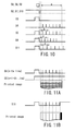
- FIG. 10 illustrates the relationship of the light modulation signals S5, S8 and S11 in terms of a printing area or a single scanning period.
- the intervals of laser beam emissions is shorter than those of laser beam emissions by means of the light modulation signal S5 that corresponds to a standard rotary speed of the polygon mirror 2.
- the intervals of laser beam emissions is longer than those of laser beam emissions by means of the light modulation signal S5.
- the pitch of forming pixels on the photosensitive member 100 is modified.
- the pitch of arrangement of pixels on the photosensitive member 100 can be regulated by regulating the rotary speed of the polygon mirror 2.
- the pitch of arrangement along the main-scanning direction of the drawn lines is reduced as shown in FIG. 7, the problem is dissolved by raising the rotary speed of the polygon mirror.
- the pitch of arrangement of the drawn lines is 46.9 mm as shown in FIG. 7, although it is supposed to be equal to 58.6 mm as shown in FIG. 6, the rotary speed of the polygon mirror 2 is raised to a level 1.25 times higher than the current level of rotary speed on the basis of the ratio of 58.6 mm/46.9 mm.
- the pitch of arrangement of the drawn lines is 70.3 mm as shown in FIG. 8, although it is supposed to be equal to 58.6 mm as shown in FIG. 6, the rotary speed of the polygon mirror 2 is reduced to a level 1/1.25 times lower than the current level of rotary speed on the basis of the ratio of 58.6 mm/70.3 mm.
- the scanning laser beam may pass the photodetector 4 before the HSYNC start signal is brought up to level "H" as a point T1 shown in FIG. 9. Then, the laser beam will be emitted continuously over a long period TA until the scanning laser beam passes the photodetector 4 the next time. Then, a straight line that does not exist in the original will be printed in the main-scanning direction by every two main scanning lines as shown in FIG. 11A.
- the laser beam is emitted continuously, starting from a time substantially in advance of the time when the scanning laser beam passes the photodetector 4.
- the laser beam may be emitted continuously while it is still operated in the effective printing area as indicated by TB in FIG. 9.
- a wrong black stripe running in the sub-scanning direction is printed as shown in FIG. 11B.
- the object of the present invention to provide a laser scanner that can regulate the pitch of arrangement of pixels in the main-scanning direction without degrading the image quality by regulating the rotary speed of the polygon mirror and a copying machine realized by using such a laser scanner.
- a laser scanner that can regulate the pitch of arrangement of pixels by regulating the rotary speed of the polygon mirror without degrading image quality.
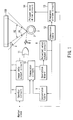
- FIG. 1 is a schematic block diagram of the first embodiment of laser scanner according to the invention, illustrating a principal part thereof.
- the laser scanner of this embodiment causes a laser beam to scan photosensitive drum 100 and makes the latter to be exposed to light as the emission of the laser beam is intermittently suspended.
- the laser scanner comprises a laser diode 1, a polygon mirror 2 operating as deflection optical system, a polygon motor 3, a photodetector 4 operating as laser detection section, an image data output circuit 5 operating as light emission control section, a counter circuit 6 operating as counting section, a operation board 7, a selected value output circuit 8, a conversion table operating as reference value output section and reference value modifying section, a comparator circuit 10 operating as forced light emission control section, an OR circuit 11, a conversion table 12, a frequency divider circuit 13 arid a polygon motor drive circuit 14.
- a horizontal synchronization detecting/control section is realized by the counter circuit 6, the conversion table 9 and the comparator circuit 10, whereas a rotary motion control section is formed by the conversion table 12, the frequency divider circuit 13 and the polygon motor drive circuit 14.
- the laser diode 1 emits a laser beam toward the polygon mirror 2 in order to irradiate the photosensitive drum 100 with the laser beam. More specifically, the laser beam emitted from the laser diode 1 is modulated according to the light modulation signal output from the OR circuit 11 as the laser diode 1 is turned ON/OFF according to the light modulation signal.
- the polygon mirror 2 is driven to rotate at a constant speed by the polygon motor 3. As a result, the laser beam emitted from the laser diode 1 is caused to scan an area indicated by A1 in FIG. 1.
- the photo detector 4 is arranged at a position corresponding to the effective area of the photo-sensitive drum 100 and located off the scanning area of the laser beam.
- the output of the photo detector 4 is brought down to level "L” and outputs an HSYNC signal only when the photo detector 4 is irradiated by the laser beam.
- the image data output circuit 5 serially outputs the data of the image to be printed on a line by line basis in synchronism with a fixed clock.
- the image data output circuit 5 determines the timing of starting to output the image data of a line according to the HSYNC signal output from the photodetector 4.
- the counter circuit 6 is provided with a master clock.
- the master clock is a reference clock that defines the timings of basic operations of the image forming device in which the laser scanner is mounted.
- the counter circuit 6 counts the master clock and supplies the count value to the comparator circuit 10.
- the count value of the counter circuit 6 is reset by an HSYNC signal.
- the operation board 7 has a key input section and other operating sections and receives user instructions for specifying a selected value for the rotary speed of the polygon mirror 2.
- the selected value output circuit 8 outputs the selected value specified by the user and received by the operation board 7.
- the conversion table 9 stores possible counts of the master clock, each of which corresponds to a scanning period of the laser beam, which by turn corresponds to each of the values that can be selected and output from the selected value output circuit 8 in the condition where such a selected value can be output from the selected value output circuit 8.
- the conversion table 9 applies the count that is stored in it and corresponds to the selected value output from the selected value output circuit 8 to the comparator circuit 10.
- the comparator circuit 10 compares the count value sent from the counter circuit 6 and the reference value given by the conversion table 9 and outputs an HSYNC start signal that is brought up to level "H" only when the count value is not smaller than the reference value.
- the OR circuit 11 adds the image data signal output from the image data output circuit 5 and the HSYNC start signal output from the comparator circuit 10 to generate a light modulation signal.
- the conversion table 12 stores predetermined frequency dividing ratios, each of which corresponds to a selected value that can be output from the selected value output circuit 8.
- the conversion table 12 outputs a frequency dividing ratio corresponding to the selected value output from the selected value output circuit 8 to the frequency divider circuit 13.
- the frequency divider circuit 13 divides the frequency of the master clock to the ratio given by the conversion table 12 and sends the signal obtained as a result of the frequency division to the polygon motor drive circuit 14 as polygon drive clock.
- the polygon motor drive circuit 14 drives the polygon motor 3 so as to make it rotate by a predetermined angle per unit time in synchronism with the polygon drive clock given from the frequency divider circuit 13.
- the polygon mirror 2 is driven to rotate by the polygon motor 3 so as to make the laser beam emitted from the laser diode 1 to scan the inside of the area A1.
- the polygon motor 3 is driven to rotate by a predetermined angle per unit time in synchronism with the polygon drive clock obtained by dividing the frequency of the master clock to a predetermined frequency dividing ratio by means of the frequency divider circuit 13.
- the rotary speed of the polygon motor 3 is determined as a function of the frequency dividing ratio of the frequency divider circuit 13.
- the operation board 7 receives an instruction of the user in order to modify the rotary speed of the polygon mirror 2. More specifically, the range of selected values that the user can specify may be between “0" and "255" and the default value (to be referred to as selected default value hereinafter) may be "128". The user can specify a value found within the above range in order to raise or reduce the rotary speed of the polygon mirror 2 by way of the operation board 7. Then, the selected value output circuit 8 output the value specified by the user. When the specified value is equal to the default value of "128", the conversion table 12 outputs a frequency dividing ratio that makes the rotary speed of the polygon motor 3 equal to the default value. In other words, when the selected value is equal to the default value of "128", the rotary speed of the polygon motor 3 will also be equal to the default value.
- the selected value output circuit 8 changes the selected value it outputs to the value specified by the user.
- the conversion table 12 stores numerical values selected to change the frequency dividing ratio at a rate inversely proportional to the change in the selected value and outputs one of the numerical value that corresponds to the selected value.
- the frequency of the polygon drive clock is reduced to by turn reduce the rotary speed of the polygon motor 3.
- the frequency of the polygon drive clock is raised to by turn raise the rotary speed of the polygon motor 3.
- the laser beam emitted from the laser diode 1 is modulated at a rate same as the rate at which image data are output from the image data output circuit 5. Additionally, since the image data output circuit 5 outputs image data at a constant rate, the laser beam is modulated at a constant rate.
- the pitch of irradiation of the laser beam that corresponds to the arrangement of pixels on the photosensitive drum 100 is changed as the rotary speed of the polygon motor 3 is changed.
- the pitch of arrangement of pixels in the main-scanning direction is regulated as the selected value is modified.
- the HSYNC signal to be used for causing the image output circuit 5 to output image data signals in synchronism with the scanning operation of the laser beam is generated by the photodetector 4, the counter circuit 6 and the comparator circuit 10 in a manner as described below.
- the photodetector 4 detects the laser beam and the counter circuit 6 is reset at the timing for bringing down the HSYNC signal to level "L".
- the counter circuit 6 counts the count of the master clock from the time when the photodetector 4 detects the laser beam.
- the count value is constantly compared with the reference value output from the conversion table 9 by the comparator circuit 10. As long as the count value is smaller than the reference value, the comparator circuit 10 holds the HSYNC signal to level "L". Therefore, only the image data signal output from the image data output circuit 5 appears in the light modulation signal.
- the comparator circuit 10 brings the HSYNC signal to level "H". As a result, the light modulation signal is constantly held to level “H” so that the photo detector 4 can detect the laser beam. Thereafter, since the counter circuit 6 is reset as a result detection by the photodetector 4 of the laser beam, the count value becomes smaller than the reference value so that the comparator circuit 10 brings back the HSYNC signal to level "L” and the emission of the laser beam is suspended continuously.
- the laser beam is forcibly emitted from the time after the elapse of a predetermined time period since the detection of the laser beam by the photodetector 4 to the next detection of the of the laser beam by the photodetector 4 so as to allow the photodetector to detect the laser beam.
- the time period from the time when the laser beam is detected by the photodetector 4 to the start of the forced emission of laser beam is defined by the reference value output from the conversion table 9, which reference value is modified by the selected value output from the selected value output circuit 8.
- the conversion table 9 stores values as shown in FIG. 2.
- the conversion table 9 outputs a numerical value that corresponds to the selected value output from the selected value output circuit 8 as reference value.
- the conversion table 9 outputs the counter default value of "9726" as reference value. Therefore, the period from the time of detection by the photodetector 4 of the laser beam to the start of the next forced emission of the laser beam is made to be equal to the period obtained by subtracting a certain margin from the scanning period corresponding to the default rotary speed of the polygon motor 3. Then, since the default value is selected for the rotary speed of the polygon motor 3, the forced emission of laser beam is started at a time slightly earlier than the time when the scanning position of the laser beam returns to the position of the photodetector 4, or at a time slightly earlier than the end of a scanning period.
- the reference value is reduced to "9688".
- the period from the detection by the photodetector 4 of the laser beam to the next forced emission of laser beam is reduced by 9688/9726 ⁇ 0.996, or about 0.4%, from the default state.
- the cycle period of forced emission of laser beam is also reduced along with the reduction of each scanning period due to a raised rotary speed of the polygon motor 3. Therefore, the forced emission of laser beam is started at a time slightly earlier than the time when the scanning laser beam returns to the position of the photodetector 4.
- the reference value is raised to "9783".
- the period from the detection by the photo detector 4 of the laser beam to the next formed emission of laser beam is extended by 9783/9726 ⁇ 1.006, or about 0.6% from the default state.
- the cycle period of forced emission of laser beam is also increased along with the increase of each scanning period due to a reduced rotary speed of the polygon motor 3. Therefore, the forced emission of laser beam is started at a time slightly earlier than the time when the scanning laser beam returns to the position of the photodetector 4.
- the emitted laser beam can become astray.
- the emission of laser beam is strictly and reliably limited to such a situation that the scanning laser beam is located outside the effective scanning area A2 and in the vicinity of the photodetector 4. Therefore, the emitted laser beam can be effectively prevented from becoming astray. In other words, of stray laser beams can be effectively prevented from occurring.
- the developing agent can be wasted due to the exposure to the laser beam in that area.
- this embodiment can reliably prevent such waste of developing agent.
- FIG. 3 is a schematic block diagram of the second embodiment of laser scanner according to the invention, illustrating a principal part thereof.
- the components same as or similar to those of the first embodiment are denoted respectively by the same reference symbols and will not be described any further.
- the laser scanner of this embodiment comprises a laser diode 1, a polygon mirror 2 operating as deflection optical system, a polygon motor 3, a photodetector 4 operating as laser detection section, an image data output circuit 5 operating as light emission control section, a operation board 7, a selected value output circuit 8, an OR circuit 11, a conversion table 12, a frequency divider circuit 13, a polygon motor drive circuit 14, a counter circuit 21 operating as forced light emission control section and a count value selecting section 22 operating as count-up value selecting section.
- a horizontal synchronization detecting/control section is realized by the counter circuit 21 and the count value selecting section.
- this embodiment is realized by replacing the counter circuit 6, the conversion table 9 and the comparator circuit 10 with the counter circuit 21 and the count value selecting section 22.
- the counter circuit 21 is provided with a master clock.
- the counter circuit 21 counts up the master clock to a count-up value that is selected in advance.
- the counter circuit 21 sets the level of its output to level "L” if the count value is short of the selected count-up value, whereas it sets the level of its output to level “H” if the count value gets to the selected count-up value.
- the output of the counter circuit 21 is applied to the OR circuit 11 as HSYNC start signal.
- the count value of the counter circuit 21 is reset by an HSYNC signal.
- the count value selecting section 22 is typically realized by using a microcomputer. If the selected value output from the selected value output circuit 8 is changed, the count value selecting section 22 counts up to the changed selected value and specifies the obtained count-up value to the counter circuit 21.
- HSYNC signals for making the image data output circuit 5 output image data signals in synchronism with the scanning laser beam are generated by the photodetector 4 and the counter circuit 21 in a manner as described below.
- the counter circuit 21 is reset at the timing of bringing the HSYNC signal down to level "L". As a result, the counter circuit 21 counts the master clock from the time when the photodetector 4 detects the laser beam. Since the counter circuit 21 holds its output level to "L” until the count value gets to the count-up value selected in advance, the HSYNC start signal remains at level "L” for a while after the detection by the photodetector 4 of the laser beam. Therefore, only the image data signal output from the image data output circuit 5 appears in the light modulation signal.
- the counter circuit 21 brings its output to level “H” and therefore the HSYNC start signal is also brought up to level “H”.
- the light modulation signal is constantly held to level “H” so that the photodetector 4 now can detect a laser beam.
- the count value falls below the selected count-up value to bring the HSYNC start signal down to level "L” and the constant emission of laser beam is suspended.
- the forced emission of laser beam continues from the time comes after a predetermined time period since the detection by the photo detector 4 of the laser beam to the time when the laser beam is detected again by the photodetector 4 so that the photodetector 4 can detect the laser beam at any time.
- the time period from the time when the laser beam is detected by the photodetector 4 to the time when the forced emission of laser beam starts is defined by the count-up value specified to the counter circuit 21.
- the count-up value is selected by the count-up selecting section 22 by means of the processing operation as described below.
- the count value selecting section 22 carries out a processing operation as shown in FIG. 4 in a predetermined operation period that may typically be the time period between the time when a start command is issued from the control section that controls the overall operation of the image forming device in which the laser scanner is mounted and the time when a stop command is issued from the control section.
- the count value selecting section 22 sets the value of the variable B computed in Step ST3 in the counter circuit 21 as count-up value (Step ST4).
- the count value selecting section 22 waits for a change in the updated selected value output from the selected value output circuit 8 that is made by substituting the variable A (Step ST5 and Step ST6).
- the count value selecting section 22 sets a count-up value that corresponds to the changed selected value in the counter circuit 21 by carrying out the steps starting from Step ST2 once again.
- the counter default value is selected as count-up value and hence the time period from the time when the laser beam is detected by the photodetector 4 to the time when the next forced emission of laser beam starts is equal to the time period obtained by subtracting a certain margin from the scanning period corresponding to the default rotary speed of the polygon motor 3. Then, as the default rotary speed is selected for the polygon motor 3, the forced emission of laser beam is started slightly before the end of the scanning period, or the time when the scanning laser beam returns to the position of the photodetector 4.
- the time period from the detection by the photodetector 4 of the laser beam to the next forced emission of laser beam is reduced by 9688/9726 ⁇ 0.996, or about 0.4%, from the default state.
- the cycle period of forced emission of laser beam is also reduced along with the reduction of each scanning period due to a raised rotary speed of the polygon motor 3. Therefore, the forced emission of laser beam is started at a time slightly earlier than the time when the scanning laser beam returns to the position of the photodetector 4.
- the period from the detection by the photo detector 4 of the laser beam to the next formed emission of laser beam is extended by 9783/9726 ⁇ 1.006, or about 0.6% from the default state.
- the cycle period of forced emission of laser beam is also increased along with the increase of each scanning period due to a reduced rotary speed of the polygon motor 3. Therefore, the forced emission of laser beam is started at a time slightly earlier than the time when the scanning laser beam returns to the position of the photodetector 4.
- the emitted laser beam can become astray.
- the emission of laser beam is strictly and reliably limited to such a situation that the scanning laser beam is located outside the effective scanning area A2 and in the vicinity of the photodetector 4. Therefore, the emitted laser beam can be effectively prevented from becoming astray. In other words, of stray laser beams can be effectively prevented from occurring.
- the developing agent can be wasted due to the exposure to the laser beam in that area.
- this embodiment can reliably prevent such waste of developing agent.
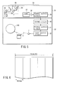
- the first or second embodiment of laser scanner may be mounted in a copying machine as shown in FIG. 5.
- the copying machine comprises a scanner section 31 and a printer section 32.
- the document 33 placed on the document table of the scanner section 31 is exposed to light emitted from exposure lamp 35 arranged on a carriage 34.
- the light irradiating the characteristics and the images on the surface of the document 33 is reflected by the mirrors arranged in carriages 34 and 36.
- the reflected light shows variations in the quantity of light per unit time to reflect the variations in the optical density of the surface of the document.
- the reflected light is focused on CCD sensor 38 by lens 37.
- the light reflected from the surface of the document and focused on the CCD sensor 38 is then transformed into a digital image signal as a result of photoelectric conversion.
- the image signal is subjected to a fundamental correcting operation of scanner control circuit 39 that relates to the original reading optical system such as the CCD sensor 38.
- the image signal is further subjected to the processing operation of system circuit 40 such as compression or expansion.
- Printer control circuit 41 performs image correction operations necessary for printing on the image data transmitted from the system circuit 40, rearranges the data good for printing an image and sends the data to the laser control circuit 42.
- the laser control circuit 42 drives the laser and corrects the temperature of the latter in order to drive the laser diode 1 for photoelectric conversion of the image data signal.
- the laser beam representing the light signal obtained by the photoelectric conversion of the image data signal performed by the laser diode 1 is then made to scan the surface of the photosensitive drum 100 for exposure.
- Embodiment 1 uses a conversion table 9 for generating reference values
- the generation of reference values may be realized by using software instead of using the conversion table 9 as in the case of Embodiment 2.
- a conversion table may alternatively be used as in the case of the first Embodiment.
- the output of the counter circuit 21 of the second Embodiment is held to level “L” until its count value that is counted up by the master clock gets to a predetermined count-up value and brought up to level “H” when the count value gets to the predetermined count-up value, it may alternatively be so arranged that the count-up value selected by the count value selecting section 22 is counted down by the counter circuit 21.
- the output of the counter circuit 21 is held to level “L” until the count value of the counter circuit 21 that is counted down by the master clock get to "0" and brought up to level "H” when the output gets to "0".
Landscapes
- Engineering & Computer Science (AREA)
- Multimedia (AREA)
- Signal Processing (AREA)
- Facsimile Scanning Arrangements (AREA)
- Mechanical Optical Scanning Systems (AREA)
- Laser Beam Printer (AREA)
- Fax Reproducing Arrangements (AREA)
Abstract
Description
S9 shows the timing that is obtained when the
The conversion table 9 applies the count that is stored in it and corresponds to the selected value output from the selected value output circuit 8 to the
As long as the count value is smaller than the reference value, the
The count-up value is selected by the count-up selecting
The document 33 placed on the document table of the
The laser beam representing the light signal obtained by the photoelectric conversion of the image data signal performed by the
Claims (16)
- A laser scanner for causing a laser beam to scan in the main-scanning direction by deflecting the laser beam by means of a deflector section, said laser scanner comprising:a speed control section (14) configured to control the rotary speed of said deflector section; anda laser detection section (4) arranged within the scanning range of said laser beam and configured to obtain a horizontal synchronizing signal by detecting said laser beam, characterized by comprisinga horizontal synchronization detecting/control section (6, 9, 10, 21, 22) configured to detect said horizontal synchronizing signal by forced emission of laser beam after a predetermined time period since the detection of said laser beam by said laser detector section, said predetermined time period being variable as a function of said rotary speed.
- The laser scanner according to claim 1, characterized in thatsaid predetermined time period is so selected that it is made short when the rotary speed of the deflector section is raised and it is made long when the rotary speed of the deflector section is reduced.
- A laser scanner according to claim 1, characterized by further comprising:a light emission control section (5) configured to control the operation of turning ON/OFF said laser beam according to image data applied to it to be carried out at a constant rate after the detection of said laser beam by said laser detector section; anda reference value changing section (8) configured to change the selected reference value so as to make it correspond to the rotary speed of said deflector section,said horizontal synchronization detecting/control section (6, 10) start a counting operation of a counter in response to the detection of said laser beam by said laser detector section and cause forced emission of laser beam in response to the completion of counting a reference value by said counter.
- The laser scanner according to claim 3, characterized by further comprising:an input section (7) configured to receive the rotary speed of said deflector section as input, said rotary speed of said deflector section input from said input section being output to said speed control section and said reference value changing section.
- The laser scanner according to claim 3, characterized in that
said horizontal synchronization detecting/control section having:a counter (6) configured to count reference clock signals after the detection of the laser beam by said laser detecting section;a reference value output section (9) configured to output said reference value; anda forced light emission control section (10) configured to compare the count value output from said counter and said reference value output from said reference value output section and causes forced emission of laser beam depending on the outcome of said comparison. - The laser scanner according to claim 3, characterized in that
said horizontal synchronization detecting/control section (21, 22) comprising:a forced light emission control section (21) configured to continue the operation of counting said clock signals until the count value gets to a predetermined value and cause forced emission of laser beam when said count value get to said predetermined value; anda count value selecting section (22) configured to select said reference value and setting it as said count value in said forced light emission control section. - The laser scanner according to claim 6, characterized in that
said count value selecting section (22) is comprised by a microcomputer. - A copying machine according to claim 3, characterized by further comprising:an image data reading section (31) configured to read image data.
- The laser scanner according to claim 8, characterized in that
said horizontal synchronization detecting/control section (21, 22) comprising:a forced light emission control section (21) configured to continue the operation of counting said clock signals until the count value gets to a predetermined value and cause forced emission of laser beam when said count value get to said predetermined value; anda count value selecting section (22) configured to select said reference value and setting it as said count value in said forced light emission control section. - The laser scanner according to claim 6, characterized in that
said count value selecting section (22) is comprised by a microcomputer. - The copying machine according to claim 8, characterized by further comprising
an input section (7) adapted to receive the rotary speed of said deflector section as input,
said rotary speed of said deflector section input from said input section being output to said speed control section and said reference value changing section. - The copying machine according to claim 8, characterized in that
said horizontal synchronization detecting/control section comprising:a counter (6) configured to count reference clock signals after the detection of the laser beam by said laser detection section;a reference value output section (9) configured to output said reference value; anda forced light emission control section (10) configured to compare the count value output from said counter and said reference value output from said reference value output section and causes forced emission of laser beam depending on the outcome of said comparison. - The copying machine according to claim 5 or 8, characterized in that
said counter (6) is reset when the laser beam is detected by said laser detection section. - The copying machine according to claim 5 or 8, characterized in that
said reference value output section (9) has a conversion table. - The copying machine according to claim 14, characterized in that
said conversion table (9) contains a variable reference value that is inversely proportional to the rotary speed of said deflector section. - A scanning method of a laser scanner adapted to cause a laser beam to scan in the main-scanning direction by deflecting the laser beam by means of a deflector section, said method comprising:detecting the laser beam; andcausing forced emission of laser beam aftera predetermined time period since the detection of said laser beam, said predetermined time period being variable as a function of said rotary speed of said deflector section.
Applications Claiming Priority (2)
| Application Number | Priority Date | Filing Date | Title |
|---|---|---|---|
| JP2001082611A JP4746756B2 (en) | 2001-03-22 | 2001-03-22 | Laser scanner |
| JP2001082611 | 2001-03-22 |
Publications (2)
| Publication Number | Publication Date |
|---|---|
| EP1244289A2 true EP1244289A2 (en) | 2002-09-25 |
| EP1244289A3 EP1244289A3 (en) | 2004-06-09 |
Family
ID=18938536
Family Applications (1)
| Application Number | Title | Priority Date | Filing Date |
|---|---|---|---|
| EP02005382A Withdrawn EP1244289A3 (en) | 2001-03-22 | 2002-03-15 | Laser scanner and a copying machine using the same |
Country Status (4)
| Country | Link |
|---|---|
| US (1) | US6680744B2 (en) |
| EP (1) | EP1244289A3 (en) |
| JP (1) | JP4746756B2 (en) |
| CN (1) | CN1228960C (en) |
Families Citing this family (4)
| Publication number | Priority date | Publication date | Assignee | Title |
|---|---|---|---|---|
| JP4340168B2 (en) * | 2003-05-08 | 2009-10-07 | 株式会社リコー | Horizontal synchronization signal state diagnosis method for optical scanning device |
| KR100677586B1 (en) * | 2005-05-23 | 2007-02-02 | 삼성전자주식회사 | Image Alignment Registration Apparatus and Method |
| JP6702768B2 (en) * | 2016-03-18 | 2020-06-03 | キヤノン株式会社 | Image forming device |
| JP2022153933A (en) * | 2021-03-30 | 2022-10-13 | 株式会社リコー | Optical writing device, image forming device and control method |
Family Cites Families (11)
| Publication number | Priority date | Publication date | Assignee | Title |
|---|---|---|---|---|
| JPS61235810A (en) * | 1985-04-12 | 1986-10-21 | Hitachi Ltd | Synchronism deciding device for laser beam printer |
| JP2771157B2 (en) * | 1986-08-05 | 1998-07-02 | キヤノン株式会社 | Optical scanning device |
| JP3082916B2 (en) * | 1988-12-05 | 2000-09-04 | キヤノン株式会社 | Recording device |
| JP3165707B2 (en) * | 1991-06-18 | 2001-05-14 | キヤノン株式会社 | Optical scanning type image forming apparatus |
| JPH05281487A (en) | 1992-04-06 | 1993-10-29 | Ricoh Co Ltd | Optical writing device |
| US5541637A (en) * | 1992-07-30 | 1996-07-30 | Brother Kogyo Kabushiki Kaisha | Image exposure apparatus with compensation for variations in scanning rate |
| JPH07234368A (en) | 1995-01-30 | 1995-09-05 | Ricoh Co Ltd | Image forming device |
| JP3647190B2 (en) * | 1997-03-25 | 2005-05-11 | キヤノン株式会社 | Image forming apparatus and control method thereof |
| JPH1134385A (en) * | 1997-07-18 | 1999-02-09 | Hitachi Koki Co Ltd | Printer control device and printer control method |
| JP2001174728A (en) * | 1999-12-15 | 2001-06-29 | Fuji Xerox Co Ltd | Lighting control method of light source and image forming apparatus |
| JP2002023096A (en) * | 2000-07-12 | 2002-01-23 | Canon Inc | Image forming method and image forming apparatus |
-
2001
- 2001-03-22 JP JP2001082611A patent/JP4746756B2/en not_active Expired - Fee Related
-
2002
- 2002-03-14 US US10/096,904 patent/US6680744B2/en not_active Expired - Fee Related
- 2002-03-15 EP EP02005382A patent/EP1244289A3/en not_active Withdrawn
- 2002-03-21 CN CNB021077517A patent/CN1228960C/en not_active Expired - Fee Related
Also Published As
| Publication number | Publication date |
|---|---|
| CN1228960C (en) | 2005-11-23 |
| EP1244289A3 (en) | 2004-06-09 |
| US20020135669A1 (en) | 2002-09-26 |
| CN1377176A (en) | 2002-10-30 |
| JP2002283611A (en) | 2002-10-03 |
| US6680744B2 (en) | 2004-01-20 |
| JP4746756B2 (en) | 2011-08-10 |
Similar Documents
| Publication | Publication Date | Title |
|---|---|---|
| EP0930773B1 (en) | Light beam scanning apparatus and image forming apparatus | |
| US11126108B2 (en) | Image forming apparatus and image forming method for correcting a position of a target image | |
| JP2000071510A (en) | Image forming device | |
| JP2588880B2 (en) | Image density correction device | |
| US6680744B2 (en) | Laser scanner and a copying machine using the same | |
| US7466472B2 (en) | Image forming apparatus, image forming method, program and computer readable information recording medium | |
| US7385732B2 (en) | Image reading apparatus, image forming apparatus and image reading method | |
| JP2008284854A (en) | Light beam scanning apparatus and image forming apparatus | |
| US7804514B2 (en) | Light beam scanning apparatus and image forming apparatus | |
| US20080100691A1 (en) | Frequency modulator | |
| JP4455084B2 (en) | Image forming apparatus | |
| JP2003103829A (en) | Image forming apparatus and resist adjustment method | |
| EP1746466B1 (en) | Optical writing device, optical writing method, and image forming apparatus | |
| JP3078421B2 (en) | Digital image forming apparatus and laser scanning light correction method for digital image forming apparatus | |
| JP4204682B2 (en) | Image forming apparatus | |
| JP4599556B2 (en) | Optical apparatus and image forming apparatus | |
| JP4866057B2 (en) | Optical device, image forming apparatus, and lighting position changing method | |
| JP4076205B2 (en) | Image forming apparatus | |
| JP3165707B2 (en) | Optical scanning type image forming apparatus | |
| JP2000289303A (en) | Image forming device | |
| JPH0575800A (en) | Optical writing controller | |
| JP2002036624A (en) | Image forming device | |
| JP2004223767A (en) | Image forming device | |
| JPH06178034A (en) | Digital copier with automatic registration correction function | |
| JPH11143306A (en) | Image data processing device |
Legal Events
| Date | Code | Title | Description |
|---|---|---|---|
| PUAI | Public reference made under article 153(3) epc to a published international application that has entered the european phase |
Free format text: ORIGINAL CODE: 0009012 |
|
| 17P | Request for examination filed |
Effective date: 20020315 |
|
| AK | Designated contracting states |
Kind code of ref document: A2 Designated state(s): AT BE CH CY DE DK ES FI FR GB GR IE IT LI LU MC NL PT SE TR |
|
| AX | Request for extension of the european patent |
Free format text: AL;LT;LV;MK;RO;SI |
|
| PUAL | Search report despatched |
Free format text: ORIGINAL CODE: 0009013 |
|
| AK | Designated contracting states |
Kind code of ref document: A3 Designated state(s): AT BE CH CY DE DK ES FI FR GB GR IE IT LI LU MC NL PT SE TR |
|
| AX | Request for extension of the european patent |
Extension state: AL LT LV MK RO SI |
|
| AKX | Designation fees paid |
Designated state(s): DE FR GB |
|
| 17Q | First examination report despatched |
Effective date: 20050608 |
|
| GRAP | Despatch of communication of intention to grant a patent |
Free format text: ORIGINAL CODE: EPIDOSNIGR1 |
|
| STAA | Information on the status of an ep patent application or granted ep patent |
Free format text: STATUS: THE APPLICATION IS DEEMED TO BE WITHDRAWN |
|
| 18D | Application deemed to be withdrawn |
Effective date: 20090221 |