EP1243874B2 - Solar collector and absorber support - Google Patents
Solar collector and absorber support Download PDFInfo
- Publication number
- EP1243874B2 EP1243874B2 EP02005085A EP02005085A EP1243874B2 EP 1243874 B2 EP1243874 B2 EP 1243874B2 EP 02005085 A EP02005085 A EP 02005085A EP 02005085 A EP02005085 A EP 02005085A EP 1243874 B2 EP1243874 B2 EP 1243874B2
- Authority
- EP
- European Patent Office
- Prior art keywords
- absorber
- solar collector
- collector according
- lower cover
- limb
- Prior art date
- Legal status (The legal status is an assumption and is not a legal conclusion. Google has not performed a legal analysis and makes no representation as to the accuracy of the status listed.)
- Expired - Lifetime
Links
Images
Classifications
-
- F—MECHANICAL ENGINEERING; LIGHTING; HEATING; WEAPONS; BLASTING
- F24—HEATING; RANGES; VENTILATING
- F24S—SOLAR HEAT COLLECTORS; SOLAR HEAT SYSTEMS
- F24S25/00—Arrangement of stationary mountings or supports for solar heat collector modules
- F24S25/20—Peripheral frames for modules
-
- F—MECHANICAL ENGINEERING; LIGHTING; HEATING; WEAPONS; BLASTING
- F24—HEATING; RANGES; VENTILATING
- F24S—SOLAR HEAT COLLECTORS; SOLAR HEAT SYSTEMS
- F24S10/00—Solar heat collectors using working fluids
- F24S10/70—Solar heat collectors using working fluids the working fluids being conveyed through tubular absorbing conduits
- F24S10/75—Solar heat collectors using working fluids the working fluids being conveyed through tubular absorbing conduits with enlarged surfaces, e.g. with protrusions or corrugations
- F24S10/753—Solar heat collectors using working fluids the working fluids being conveyed through tubular absorbing conduits with enlarged surfaces, e.g. with protrusions or corrugations the conduits being parallel to each other
-
- F—MECHANICAL ENGINEERING; LIGHTING; HEATING; WEAPONS; BLASTING
- F24—HEATING; RANGES; VENTILATING
- F24S—SOLAR HEAT COLLECTORS; SOLAR HEAT SYSTEMS
- F24S25/00—Arrangement of stationary mountings or supports for solar heat collector modules
- F24S25/60—Fixation means, e.g. fasteners, specially adapted for supporting solar heat collector modules
- F24S25/63—Fixation means, e.g. fasteners, specially adapted for supporting solar heat collector modules for fixing modules or their peripheral frames to supporting elements
- F24S25/632—Side connectors; Base connectors
-
- F—MECHANICAL ENGINEERING; LIGHTING; HEATING; WEAPONS; BLASTING
- F24—HEATING; RANGES; VENTILATING
- F24S—SOLAR HEAT COLLECTORS; SOLAR HEAT SYSTEMS
- F24S80/00—Details, accessories or component parts of solar heat collectors not provided for in groups F24S10/00-F24S70/00
- F24S80/40—Casings
-
- F—MECHANICAL ENGINEERING; LIGHTING; HEATING; WEAPONS; BLASTING
- F24—HEATING; RANGES; VENTILATING
- F24S—SOLAR HEAT COLLECTORS; SOLAR HEAT SYSTEMS
- F24S25/00—Arrangement of stationary mountings or supports for solar heat collector modules
- F24S2025/01—Special support components; Methods of use
- F24S2025/011—Arrangements for mounting elements inside solar collectors; Spacers inside solar collectors
-
- F—MECHANICAL ENGINEERING; LIGHTING; HEATING; WEAPONS; BLASTING
- F24—HEATING; RANGES; VENTILATING
- F24S—SOLAR HEAT COLLECTORS; SOLAR HEAT SYSTEMS
- F24S25/00—Arrangement of stationary mountings or supports for solar heat collector modules
- F24S2025/01—Special support components; Methods of use
- F24S2025/016—Filling or spacing means; Elastic means
-
- F—MECHANICAL ENGINEERING; LIGHTING; HEATING; WEAPONS; BLASTING
- F24—HEATING; RANGES; VENTILATING
- F24S—SOLAR HEAT COLLECTORS; SOLAR HEAT SYSTEMS
- F24S25/00—Arrangement of stationary mountings or supports for solar heat collector modules
- F24S2025/01—Special support components; Methods of use
- F24S2025/017—Tensioning means
-
- Y—GENERAL TAGGING OF NEW TECHNOLOGICAL DEVELOPMENTS; GENERAL TAGGING OF CROSS-SECTIONAL TECHNOLOGIES SPANNING OVER SEVERAL SECTIONS OF THE IPC; TECHNICAL SUBJECTS COVERED BY FORMER USPC CROSS-REFERENCE ART COLLECTIONS [XRACs] AND DIGESTS
- Y02—TECHNOLOGIES OR APPLICATIONS FOR MITIGATION OR ADAPTATION AGAINST CLIMATE CHANGE
- Y02E—REDUCTION OF GREENHOUSE GAS [GHG] EMISSIONS, RELATED TO ENERGY GENERATION, TRANSMISSION OR DISTRIBUTION
- Y02E10/00—Energy generation through renewable energy sources
- Y02E10/40—Solar thermal energy, e.g. solar towers
- Y02E10/44—Heat exchange systems
-
- Y—GENERAL TAGGING OF NEW TECHNOLOGICAL DEVELOPMENTS; GENERAL TAGGING OF CROSS-SECTIONAL TECHNOLOGIES SPANNING OVER SEVERAL SECTIONS OF THE IPC; TECHNICAL SUBJECTS COVERED BY FORMER USPC CROSS-REFERENCE ART COLLECTIONS [XRACs] AND DIGESTS
- Y02—TECHNOLOGIES OR APPLICATIONS FOR MITIGATION OR ADAPTATION AGAINST CLIMATE CHANGE
- Y02E—REDUCTION OF GREENHOUSE GAS [GHG] EMISSIONS, RELATED TO ENERGY GENERATION, TRANSMISSION OR DISTRIBUTION
- Y02E10/00—Energy generation through renewable energy sources
- Y02E10/40—Solar thermal energy, e.g. solar towers
- Y02E10/47—Mountings or tracking
Definitions
- the invention relates to a solar collector.
- a first solar collector or a solar collector is from the DE 199 15 504 A1 known.
- the structure of this solar collector has proven itself. In the assembled position, the top cover is directed towards the sun. Below are the absorber, the thermal insulation material and the sun's radiation away from the ground or the lower cover.
- a disadvantage of the known types of mounting for absorbers is that the absorber e.g. can slip during transport or during assembly.
- the absorber should be secured against slipping and it should be possible for a free expansion in thermal changes.
- the invention solves this problem by the subject matter of claim 1.
- the spring element ensures structurally simple manner uncomplicated installation and the necessary thermal mobility of the absorber holder, which avoids tension and damage to the absorber sheets.
- the absorber holder also has at its end facing the absorber on a holding leg for grasping the absorber edge or for engaging in a recess of the absorber.
- the holding leg is designed to engage in the axial end of a tube arranged on the absorber, which points with its free end to the collector frame.
- the absorber holder is preferably designed to resiliently enclose the absorber relative to the rest of the collector.
- the absorber holder is further mounted on the lower cover, pivotally, so that simply by pivoting the absorber holder, a fixation of the absorber in the solar collector can be achieved.
- the absorber holder as a wire bow, which can be suspended with one of its free ends pivotally in receptacles in the lower cover.
- the formation of the absorber holder as a wire hanger can be realized particularly inexpensive. For example, it makes sense to manufacture the wire clip from spring steel wire.
- a wire can relatively easily be accommodated in lower cover receptacles, e.g. Tabs or eyes, rotatably mounted.
- a fixation can be achieved in a simple manner by a bend of the wire bracket.
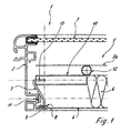
- FIG. 1 shows a solar collector 1 with a housing, which is formed here of a frame with frame profiles 2, which surround the solar collector on its outer sides.
- the frame profile holds an upper, the sun opposing cover - usually a glass 3 - a lower cover - usually a plate. 4
- the actual absorber is arranged, which lies over an insulating layer 6, which in turn is arranged on the sheet 4.
- the absorber has here an absorber plate 5a and pipes 12 to the water pipe.
- the absorber with baffles for a hot air collector.
- a pipe section 10 In the edge region between the absorber 5 and the frame profile 2 is located below the absorber plate 5a, a pipe section 10.
- the tube is formed substantially perpendicular to the main extension of the frame profile 2.
- an absorber holder 7 In the free end of the tube 10, which faces the frame section 2, engages an absorber holder 7, which is designed here as a wire bracket made of spring steel wire.
- the wire hanger engages in the lower area in a tab 8 of the bottom plate 4 a.
- Tabs 8 in the floor panel 4 can be formed in a simple manner by punching. It is advantageous that the tabs 8 can still form above the frame profile 2, so that the punches for the tabs 8 are not visible from the outside and do not lead to leaks.
- the wire hanger has at one of its ends on a leg which is guided as a rotation axis 9 through the bottom plate tab 8. Directly behind the bottom plate tab 8 of the wire bow is bent upwards and extends in the locking position for the absorber to the absorber, in which it engages with a retaining leg 13, which is formed by a U-shaped bent portion of the wire bracket.
- a spring element of the leg which protrudes from the tube 10
- the holder 7 is also resiliently supported on the frame profile 2.
- the rotation axis 9 of the holder 7 is pivotally mounted on the bottom 4, i. it can be tilted to the side to insert the absorber 5 in the solar panel 1.
- the absorber 5 is fixed in a simple manner in the solar collector, wherein the supported on the collector frame 2 spring element 11 allows the compensation of material strains in case of temperature fluctuations in a simple manner.
- the holding leg 13 may also be formed so as to receive the absorber sheet 5a, e.g. U-shaped at the edge surrounds (not shown here).
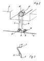
- FIG. 2 shows a partial excerpt FIG. 1 in isometric view. It can be seen clearly the insulation 6 and the free end of the tube 10, in which engages the absorber holder or the holding leg 13 of the absorber holder.
- a cranked end 14 at the end of the axis of rotation 9 forming leg of the wire bracket prevents the slide out of the holder 7 in the assembled position.
- the spring element 11 either by a straight leg according to the illustration of FIG. 3 as well as by a cranked training or by another spring element (eg a coil spring) can be formed.
- the collector holder as in the side view substantially Z-shaped plate, one leg of the Z is fixed to the bottom plate and wherein the further leg of the Z engages in a free tube end of the tube 10 (here not shown). It is important that this Z-shaped holder is supported by a spring leg on the solar collector, the spring action should also be designed so that for mounting the absorber 5 a sufficiently wide folding back of the absorber holder 7 is possible. It should also be noted that it is also possible to use the absorber holder instead of corrosion-free spring steel, e.g. made of plastic or other material, which has the required spring properties.
Abstract
Description
Die Erfindung betrifft einen Sonnenkollektor.The invention relates to a solar collector.
Ein erster Sonnenkollektor bzw. ein Solarkollektor ist aus der
Weiterhin ist aus der
Aus dem Stand der Technik ist es bekannt, die Absorbermontage einfach dadurch zu bewerkstelligen, daß die Absorber in den Rahmen oder ein sonstiges Gehäuse eingelegt werden. Teilweise werden hierbei die Absorber durch die Verbindung der Absorberrohrleitungen gehalten, teilweise ist es auch üblich, die Absorber mehr oder weniger formschlüssig in das Dämmaterial einzubetten.From the prior art, it is known to accomplish the absorber assembly simply by the absorbers are inserted into the frame or other housing. In some cases, the absorbers are held by the connection of the absorber pipes, sometimes it is also common to embed the absorber more or less positively in the insulating material.
Es ist ebenfalls bekannt, Absorberbleche in Nuten zu klemmen oder starr an der Außenwand des Kollektors zu befestigen.It is also known to clamp absorber sheets in grooves or rigidly attach to the outer wall of the collector.
Nachteilig an den bekannten Montagearten für Absorber ist es, daß der Absorber z.B. beim Transport oder bei der Montage verrutschen kann.A disadvantage of the known types of mounting for absorbers is that the absorber e.g. can slip during transport or during assembly.
Nach einer Erkenntnis der Erfindung ist es ferner nachteilig, den Absorber starr im Kollektorgehäuse oder am Kollektorrahmen zu montieren, da eine starre Befestigung nicht die erforderliche thermische Beweglichkeit gewährleistet, welche bei größeren Wärmeschwankungen erforderlich ist, um Spannungen und Beschädigungen der Absorberfläche zu vermeiden.After a finding of the invention, it is also disadvantageous to mount the absorber rigidly in the collector housing or on the collector frame, since a rigid attachment does not ensure the required thermal mobility, which is required for larger heat fluctuations to avoid tension and damage to the absorber surface.
Gerade die bekannten Montagearten, welche eine starre Befestigung des Absorbers im Sonnenkollektor lehren, bringen zudem den Nachteil mit sich, daß die Montage des Absorbers relativ umständlich und zeitaufwendig ist, da z. B. wie in der
Es ist daher die Aufgabe der Erfindung, den gattungsgemäßen Sonnenkollektor dahingehend weiterzuentwickeln, daß die Montage des Absorbers im Sonnenkollektor auf konstruktiv einfache Weise ermöglicht wird. Vorzugsweise soll der Absorber dabei gegen ein Verrutschen gesichert sein und es soll ein freies Ausdehnen bei thermischen Veränderungen möglich sein.It is therefore an object of the invention to develop the generic solar collector to the effect that the assembly of the absorber in the solar collector is made possible in a structurally simple manner. Preferably, the absorber should be secured against slipping and it should be possible for a free expansion in thermal changes.
Die Erfindung löst diese Aufgabe durch den Gegenstand des Anspruches 1. Das Federelement gewährleistet auf konstruktiv einfache Weise eine unkomplizierte Montage und die nötige thermische Beweglichkeit der Absorberhalterung, was Spannungen und Beschädigungen der Absorberbleche vermeidet.The invention solves this problem by the subject matter of claim 1. The spring element ensures structurally simple manner uncomplicated installation and the necessary thermal mobility of the absorber holder, which avoids tension and damage to the absorber sheets.
Nach der Erfindung weist der Absorberhalter zudem an seinem dem Absorber zugewandten Ende einen Halteschenkel zum Umgreifen des Absorberrandes oder zum Eingriff in eine Ausnehmung des Absorbers auf. Insbesondere hat es sich bewährt, wenn der Halteschenkel zum Eingriff in das axiale Ende eines am Absorber angeordneten Rohres ausgelegt ist, welches mit seinem freien Ende zum Kollektorrahmen zeigt.According to the invention, the absorber holder also has at its end facing the absorber on a holding leg for grasping the absorber edge or for engaging in a recess of the absorber. In particular, it has proven useful if the holding leg is designed to engage in the axial end of a tube arranged on the absorber, which points with its free end to the collector frame.
Bevorzugt ist dazu der Absorberhalter dazu ausgelegt, den Absorber relativ zum übrigen Kollektor federnd einzufassen.For this purpose, the absorber holder is preferably designed to resiliently enclose the absorber relative to the rest of the collector.
Nach Erfindung ist der Absorberhalter weiterhin an der unteren Abdeckung, verschwenkbar gelagert, so daß einfach durch das Verschwenken des Absorberhalters eine Fixierung des Absorbers im Sonnenkollektor erzielbar ist.After the invention, the absorber holder is further mounted on the lower cover, pivotally, so that simply by pivoting the absorber holder, a fixation of the absorber in the solar collector can be achieved.
Eine umständliche Montage mit Schrauben oder sonstigen Befestigungselementen wird auf diese Weise vermieden und die Montage wird deutlich vereinfacht.A cumbersome installation with screws or other fasteners is avoided in this way and the installation is greatly simplified.
Nach einer weiteren besonders bevorzugten Variante der Erfindung ist vorgesehen, den Absorberhalter als Drahtbügel auszubilden, welcher mit einem seiner freien Enden verschwenkbar in Aufnahmen in der unteren Abdeckung einhängbar ist. Die Ausbildung des Absorberhalters als Drahtbügel läßt sich besonders kostengünstig realisieren. Es bietet sich beispielsweise an, den Drahtbügel aus Federstahldraht zu fertigen.According to a further particularly preferred variant of the invention, it is provided to form the absorber holder as a wire bow, which can be suspended with one of its free ends pivotally in receptacles in the lower cover. The formation of the absorber holder as a wire hanger can be realized particularly inexpensive. For example, it makes sense to manufacture the wire clip from spring steel wire.
Zudem kann ein Draht relativ einfach in Aufnahmen der unteren Abdeckung, z.B. Laschen oder Ösen, drehbar gelagert werden. Eine Fixierung läßt sich auf einfache Weise durch eine Abkröpfung des Drahtbügels erreichen.In addition, a wire can relatively easily be accommodated in lower cover receptacles, e.g. Tabs or eyes, rotatably mounted. A fixation can be achieved in a simple manner by a bend of the wire bracket.
Es ist ferner möglich, eine Auslegung des Absorberhalters als Drahtbügel und ein freies Ende des Drahtbügels dazu zu nutzen, eine federnde Vorspannung zwischen dem Absorber und der Kollektorwandung bzw. dem Kollektorrahmen zu erzielen.It is also possible to use a design of the absorber holder as a wire bracket and a free end of the wire bracket to achieve a resilient bias between the absorber and the collector wall or the collector frame.
Besonders bevorzugt wird der Bügeldraht des Drahtbügels wie folgt ausgebildet:
- der Drahtbügel weist in einer ersten Ansicht im wesentlichen eine Art L-Form auf,
- wobei der kürzere Schenkel des L verschwenkbar an der unteren Abdeckung gelagert ist,
- wobei ferner der längere Schenkel des L wiederum zu einer Art U gebogen ist und der Grundbereich des U-Schenkels derartig zum übrigen Schenkel abgebogen ist, daß er als Halteschenkel mit dem Absorber in Eingriff steht,
- wobei der freie Schenkel des U das sich am Kollektorrahmen abstützende Federelement ausbildet.
- the wire bow has in a first view essentially a kind of L-shape,
- wherein the shorter leg of the L is pivotally mounted on the lower cover,
- further wherein the longer leg of the L is in turn bent to a kind U and the base portion of the U-leg is bent in such a way to the remaining leg that it is in the form of a holding leg with the absorber,
- wherein the free leg of the U forms the collector frame supporting spring element.
Mit dieser Variante der Erfindung wird auf kostengünstige Weise sowohl die Verschwenkbarkeit des Absorberhalters als auch die federnde Abstützung am übrigen Sonnenkollektor realisierbar.With this variant of the invention is on cost-effective manner, both the pivotability of the absorber holder and the resilient support on the remaining solar panel feasible.
Nachfolgend wird die Erfindung anhand von Ausführungsbeispielen unter Bezug auf die Zeichnung näher beschrieben.The invention will be described in more detail by means of exemplary embodiments with reference to the drawing.
Es zeigt:
- Figur 1
- einen Schnitt eines Randbereiches eines Sonnenkollektors;
Figur 2- eine perspektivische Ansicht eines Ausschnitts aus
Figur 1 und - Figur 3
- eine Seitenansicht eines Absorberhalters.
- FIG. 1
- a section of an edge region of a solar collector;
- FIG. 2
- a perspective view of a section
FIG. 1 and - FIG. 3
- a side view of an absorber holder.
Die
Das Rahmenprofil hält eine obere, der Sonne entgegengerichtete Abdeckung - in der Regel eine Glasscheibe 3 - eine untere Abdeckung - in der Regel ein Blech 4.The frame profile holds an upper, the sun opposing cover - usually a glass 3 - a lower cover - usually a plate. 4
Im Inneren des Sonnenkollektors ist der eigentliche Absorber angeordnet, welcher über einer Dämmschicht 6 liegt, welche wiederum auf dem Blech 4 angeordnet ist.In the interior of the solar collector, the actual absorber is arranged, which lies over an
Der Absorber weist hier ein Absorberblech 5a sowie Rohre 12 zur Wasserleitung auf. Alternativ ist es auch möglich, den Absorber mit Leitblechen für einen Warmluftkollektor zu versehen.The absorber has here an absorber plate 5a and
Im Randbereich zwischen dem Absorber 5 und dem Rahmenprofil 2 liegt unterhalb des Absorberbleches 5a ein Rohrstück 10. Das Rohr ist im wesentlichen senkrecht zur Haupterstreckung des Rahmenprofils 2 ausgebildet. In das freie Ende des Rohres 10, welches zum Rahmenprofil 2 hin zeigt, greift ein Absorberhalter 7 ein, der hier als Drahtbügel aus Federstahldraht ausgebildet ist.In the edge region between the
Der Drahtbügel greift im unteren Bereich in eine Lasche 8 des Bodenbleches 4 ein. Laschen 8 im Bodenblech 4 lassen sich auf einfache Weise durch Stanzen ausbilden. Dabei ist es vorteilhaft, daß sich die Laschen 8 noch oberhalb des Rahmenprofils 2 ausbilden lassen, so daß die Stanzungen für die Laschen 8 von außen nicht sichtbar sind und nicht zu Undichtigkeiten führen.The wire hanger engages in the lower area in a
Der Drahtbügel weist an einem seiner Enden einen Schenkel auf, der als Drehachse 9 durch die Bodenblechlasche 8 geführt ist. Direkt hinter der Bodenblechlasche 8 ist der Drahtbügel nach oben hin abgebogen und erstreckt sich in der Arretierstellung für den Absorber bis zum Absorber, in welches er mit einem Halteschenkel 13 eingreift, welcher durch einen U-förmig gebogenen Abschnitt des Drahtbügels ausgebildet wird. Mittels eines Federelements des Schenkels, welches aus dem Rohr 10 vorsteht, ist der Halter 7 zudem federnd am Rahmenprofil 2 abgestützt.The wire hanger has at one of its ends on a leg which is guided as a
Durch die Drehachse 9 ist der Halter 7 am Boden 4 verschwenkbar gelagert, d.h. er kann zur Seite gekippt werden, um den Absorber 5 in den Sonnenkollektor 1 einzusetzen. Sodann wird der Absorberhalter 1 bzw. werden vorteilhafterweise zwei Absorberhalter 7 auf einander gegenüberliegenden Seiten des Absorbers 5 in die Arretierstellung verschwenkt, in welcher die Halteschenkel der drahtbügelartigen Absorberhalter 7 jeweils in die freien Enden der Rohre 10 eingreifen. Hierdurch wird der Absorber 5 auf einfache Weise im Sonnenkollektor fixiert, wobei das am Kollektorrahmen 2 abgestützte Federelement 11 auf einfache Weise den Ausgleich von Materialdehnungen bei Temperaturschwankungen ermöglicht.By the
Alternativ kann der Halteschenkel 13 auch derart ausgebildet sein, daß er das Absorberblech 5a z.B. U-förmig am Rand umgreift (hier nicht dargestellt).Alternatively, the holding
Ein gekröpftes Ende 14 am Ende des die Drehachse 9 bildenden Schenkels des Drahtbügels verhindert das Herausgleiten des Halters 7 in der Montagestellung.A cranked
Angemerkt werden soll noch, daß das Federelement 11 entweder durch einen geraden Schenkel gemäß der Darstellung der
Abschließend sei erwähnt, daß es auch denkbar ist, den Kollektorhalter als in der Seitenansicht im wesentlichen Z-förmiges Blech auszubilden, wobei ein Schenkel des Z am Bodenblech befestigt ist und wobei der weitere Schenkel des Z in ein freies Rohrende des Rohres 10 eingreift (hier nicht dargestellt). Wichtig ist dabei, daß dieser Z-förmige Halter mittels eines Federschenkels am Sonnenkollektor abgestützt ist, wobei die Federwirkung ferner derart ausgelegt sein soll, daß zum Montieren des Absorbers 5 ein genügend weites Zurückklappen des Absorberhalters 7 möglich ist. Angemerkt werden soll noch, daß es auch möglich ist, den Absorberhalter anstelle von korrosionsfreiem Federstahl z.B. aus Kunststoff oder einem sonstigen Material herzustellen, welches die geforderten Federeigenschaften aufweist.Finally, it should be mentioned that it is also conceivable to form the collector holder as in the side view substantially Z-shaped plate, one leg of the Z is fixed to the bottom plate and wherein the further leg of the Z engages in a free tube end of the tube 10 (here not shown). It is important that this Z-shaped holder is supported by a spring leg on the solar collector, the spring action should also be designed so that for mounting the absorber 5 a sufficiently wide folding back of the
- 11
- Sonnenkollektorsolar panel
- 22
- Rahmenprofilframe profile
- 33
- Glasscheibepane
- 44
- Blechsheet
- 55
- Absorberabsorber
- 5a5a
- Absorberblechabsorber plate
- 66
- Dämmschichtdamp course
- 77
- Halterholder
- 88th
- BodenblechlascheFloor panel flap
- 99
- Drehachseaxis of rotation
- 1010
- Rohrpipe
- 1111
- Federelementspring element
- 1212
- 1313
- Halteschenkelholding leg
- 1414
- EndeThe End
Claims (12)
- Solar collector having a frame, preferably comprising frame profiles (2), and having a lower cover - in particular a plate (4) - and having an upper cover - in particular a panel (3) - and having an absorber (5) which has at least one absorber plate (5a) and which is preferably arranged above an insulating layer (6) between the lower and the upper cover, the absorber (5) being secured to the solar collector by means of an absorber support (7) which has a spring element (11), wherein the absorber support is mounted on the lower cover (4) of the solar collector such that it can pivot, and wherein, at its end which faces away from the lower cover (4), the absorber support (7) has a retaining limb (13) for surrounding the absorber edge or for engaging in a recess in the absorber (5) wherein the spring element is a spring web which is supported on the frame of the absorber.
- Solar collector according to Claim 1, characterized in that the retaining limb (13) is designed to engage in the axial, free end of a tube (10) which is arranged on the absorber (5).
- Solar collector according to one of the preceding claims, characterized in that the absorber support (7) is in the form of a wire bracket which can be suspended by one of its ends (rotation shaft 9) in holding devices (8) in the lower cover such that it can pivot.
- Solar collector according to Claim 3, characterized in that the wire bracket is composed of stainless spring steel.
- Solar collector according to one of the preceding claims, characterized in that the holding devices in the base plate are in the form of punched-out sections (8) in the base plate (4) or lugs attached to the lower cover.
- Solar collector according to Claim 3 or 4, characterized in that, in a first view, the wire bracket essentially has a type of L shape, with the shorter limb of the L being mounted on the lower cover (4) such that it can pivot, and with the longer limb of the L again being bent into a type of U, the base region of the U being in the form of a retaining limb (13) for engaging in the absorber (5), and a free limb of the wire bracket forming the spring element which is supported on the collector frame (2).
- Solar collector according to Claim 3, 4 or 6, characterized in that the limb of the absorber support which forms the rotation shaft (9) is provided with a bent section (14) which retains/fixes the wire bracket on the lower absorber plate (4).
- Solar collector according to one of the preceding claims, characterized in that a multiplicity of absorber supports (7) is mounted on the lower cover (4).
- Solar collector according to one of the preceding claims, characterized in that the absorber (5) is fixed to the solar collector (1) by means of two absorber supports (7) which are arranged on two mutually opposite sides.
- Solar collector according to one of the preceding claims, characterized in that the absorber support is in the form of a substantially Z-shaped plate.
- Solar collector according to one of Claims 3, 4, 6 or 7, characterized in that the holding devices for holding the wire bracket in the base of the absorber support are in the form of lugs in the base plate (4), these lugs being covered by the frame profile (2).
- Solar collector according to one of the preceding claims, characterized in that the retaining limb (13) of the absorber support (7) holds the edge of the absorber plate (5a) in a U-shaped manner.
Applications Claiming Priority (2)
| Application Number | Priority Date | Filing Date | Title |
|---|---|---|---|
| DE20105162U | 2001-03-23 | ||
| DE20105162U DE20105162U1 (en) | 2001-03-23 | 2001-03-23 | Solar panel and absorber holder |
Publications (4)
| Publication Number | Publication Date |
|---|---|
| EP1243874A2 EP1243874A2 (en) | 2002-09-25 |
| EP1243874A3 EP1243874A3 (en) | 2004-03-03 |
| EP1243874B1 EP1243874B1 (en) | 2006-05-31 |
| EP1243874B2 true EP1243874B2 (en) | 2009-10-28 |
Family
ID=7954805
Family Applications (1)
| Application Number | Title | Priority Date | Filing Date |
|---|---|---|---|
| EP02005085A Expired - Lifetime EP1243874B2 (en) | 2001-03-23 | 2002-03-07 | Solar collector and absorber support |
Country Status (5)
| Country | Link |
|---|---|
| EP (1) | EP1243874B2 (en) |
| AT (1) | ATE328252T1 (en) |
| DE (2) | DE20105162U1 (en) |
| ES (1) | ES2261539T5 (en) |
| PT (1) | PT1243874E (en) |
Families Citing this family (6)
| Publication number | Priority date | Publication date | Assignee | Title |
|---|---|---|---|---|
| DE602005014394D1 (en) * | 2005-06-16 | 2009-06-18 | Vkr Holding As | SOLAR PANEL |
| DE202007002920U1 (en) | 2007-02-26 | 2007-07-05 | Kbb Kollektorbau Gmbh | Solar collector has transparent cover plate, and two connecting unit subjecting heat exchanger to stress are arranged between heat exchanger and retaining frame |
| IL183052A (en) * | 2007-05-08 | 2011-04-28 | Magen Eco Energy A C S Ltd | Enclosure for a solar collector |
| DE102010010899B4 (en) * | 2010-03-05 | 2020-02-13 | Handtmann Systemtechnik Gmbh | solar collector |
| DE102010021426B4 (en) * | 2010-05-25 | 2013-10-02 | Handtmann Systemtechnik Gmbh | solar collector |
| DE202011109586U1 (en) | 2011-12-24 | 2012-01-30 | Institut Für Solarenergieforschung Gmbh | Solar collector with glass pane arranged upwards, which reduces heat radiation and which is in direct contact with the top-down heat exchanger combination |
Citations (3)
| Publication number | Priority date | Publication date | Assignee | Title |
|---|---|---|---|---|
| JPH02233943A (en) † | 1989-03-03 | 1990-09-17 | Takashi Mori | Solar heat collecting device |
| JPH035670A (en) † | 1989-06-01 | 1991-01-11 | Takashi Mori | Sunlight collection device |
| DE19904646A1 (en) † | 1999-02-05 | 2000-08-10 | Horst Schwarz | Solar collector comprises symmetrical, transparent, self-supporting housing consisting of two equal machined, automatically produced housing halves formed after joining with prefabricated absorber |
Family Cites Families (5)
| Publication number | Priority date | Publication date | Assignee | Title |
|---|---|---|---|---|
| US4341200A (en) * | 1978-08-21 | 1982-07-27 | Ametek, Inc. | Solar energy collector sub-assemblies and combinations thereof |
| US4201190A (en) * | 1978-08-21 | 1980-05-06 | Ametek, Inc. | Solar energy collector assembly and sub-assemblies thereof |
| US4214575A (en) * | 1979-01-24 | 1980-07-29 | Sunworks, Inc. | Solar energy collector |
| DE19752594A1 (en) * | 1997-11-27 | 1999-06-10 | Detlef Fischer | Solar collector panel of absorber plates with tubes and air cushion seal |
| DE19915504B4 (en) | 1999-04-07 | 2006-07-20 | SCHÜCO International KG | Frame profile for a solar collector |
-
2001
- 2001-03-23 DE DE20105162U patent/DE20105162U1/en not_active Expired - Lifetime
-
2002
- 2002-03-07 DE DE50206953T patent/DE50206953D1/en not_active Expired - Lifetime
- 2002-03-07 AT AT02005085T patent/ATE328252T1/en not_active IP Right Cessation
- 2002-03-07 PT PT02005085T patent/PT1243874E/en unknown
- 2002-03-07 ES ES02005085T patent/ES2261539T5/en not_active Expired - Lifetime
- 2002-03-07 EP EP02005085A patent/EP1243874B2/en not_active Expired - Lifetime
Patent Citations (3)
| Publication number | Priority date | Publication date | Assignee | Title |
|---|---|---|---|---|
| JPH02233943A (en) † | 1989-03-03 | 1990-09-17 | Takashi Mori | Solar heat collecting device |
| JPH035670A (en) † | 1989-06-01 | 1991-01-11 | Takashi Mori | Sunlight collection device |
| DE19904646A1 (en) † | 1999-02-05 | 2000-08-10 | Horst Schwarz | Solar collector comprises symmetrical, transparent, self-supporting housing consisting of two equal machined, automatically produced housing halves formed after joining with prefabricated absorber |
Also Published As
| Publication number | Publication date |
|---|---|
| EP1243874A2 (en) | 2002-09-25 |
| DE20105162U1 (en) | 2001-06-13 |
| PT1243874E (en) | 2006-09-29 |
| DE50206953D1 (en) | 2006-07-06 |
| ES2261539T3 (en) | 2006-11-16 |
| EP1243874A3 (en) | 2004-03-03 |
| EP1243874B1 (en) | 2006-05-31 |
| ES2261539T5 (en) | 2010-04-05 |
| ATE328252T1 (en) | 2006-06-15 |
Similar Documents
| Publication | Publication Date | Title |
|---|---|---|
| EP1593908B1 (en) | Fluorescent lamp holder | |
| DE102005002838B4 (en) | Holder for a video projector | |
| EP1243874B2 (en) | Solar collector and absorber support | |
| DE10228883B3 (en) | Holding clamp for fixing the getters in containers of any cross-section in closed vacuum systems and container for use in closed vacuum systems, especially collector pipe | |
| DE202005010363U1 (en) | Sealing element for solar collectors has flange part for mounting element to collector housing, connected to tubular part containing pipes | |
| DE102006017224A1 (en) | Anti-roll bar fastening device for motor vehicle, has bearing unit surrounding section of anti-roll bar, and clamp-shaped component for retaining bearing unit and section of bar, where fastening units fasten clamp-shaped component | |
| DE4307604B4 (en) | Holder for a lamp | |
| DE102017007324A1 (en) | Facade construction unit | |
| DE3725632A1 (en) | Rigid guide elbow for plastics pipes | |
| DE8615470U1 (en) | Pipe guide bend | |
| DE202015106900U1 (en) | Mast device with base for a lightning mast | |
| DE102008052136A1 (en) | Guide rail for cable-traction window regulator of motor vehicle, has guide roller for redirecting cable of cable-traction window regulator, guide receiving external traction, and catch supporting front side of external traction | |
| EP3073169B1 (en) | Open accessory with spring tension | |
| DE102022106755B4 (en) | Winding device for use on a sun protection device | |
| DE2545483C3 (en) | Electric coffee maker | |
| DE102016218723B4 (en) | Device for compensating length changes of plastic pipes | |
| EP3372915B1 (en) | Fluidic installation | |
| EP1272797B1 (en) | Lamp supports, in particular for low voltage lamps and fittings, in particular table, standard or wall lamps | |
| DE1441725C (en) | Clamp for the joint ball of a rod antenna | |
| DE10163679C1 (en) | Fixing clamp securing oscillation damper to overhead line cable has oscillation damper inserted in U-shaped open channel by movement perpendicular to its longitudinal direction | |
| DE2911884C2 (en) | Spacers | |
| EP3196527A1 (en) | Support assembly | |
| DE202006012516U1 (en) | Sun protection device | |
| EP0272370A1 (en) | Guiding bend for a pipe | |
| DE2405388C3 (en) | Cross profile clamp for suspended ceilings |
Legal Events
| Date | Code | Title | Description |
|---|---|---|---|
| PUAI | Public reference made under article 153(3) epc to a published international application that has entered the european phase |
Free format text: ORIGINAL CODE: 0009012 |
|
| AK | Designated contracting states |
Kind code of ref document: A2 Designated state(s): AT BE CH CY DE DK ES FI FR GB GR IE IT LI LU MC NL PT SE TR |
|
| AX | Request for extension of the european patent |
Free format text: AL;LT;LV;MK;RO;SI |
|
| PUAL | Search report despatched |
Free format text: ORIGINAL CODE: 0009013 |
|
| AK | Designated contracting states |
Kind code of ref document: A3 Designated state(s): AT BE CH CY DE DK ES FI FR GB GR IE IT LI LU MC NL PT SE TR |
|
| AX | Request for extension of the european patent |
Extension state: AL LT LV MK RO SI |
|
| 17P | Request for examination filed |
Effective date: 20040824 |
|
| AKX | Designation fees paid |
Designated state(s): AT BE CH CY DE DK ES FI FR GB GR IE IT LI LU MC NL PT SE TR |
|
| 17Q | First examination report despatched |
Effective date: 20041112 |
|
| GRAP | Despatch of communication of intention to grant a patent |
Free format text: ORIGINAL CODE: EPIDOSNIGR1 |
|
| GRAS | Grant fee paid |
Free format text: ORIGINAL CODE: EPIDOSNIGR3 |
|
| GRAA | (expected) grant |
Free format text: ORIGINAL CODE: 0009210 |
|
| AK | Designated contracting states |
Kind code of ref document: B1 Designated state(s): AT BE CH CY DE DK ES FI FR GB GR IE IT LI LU MC NL PT SE TR |
|
| PG25 | Lapsed in a contracting state [announced via postgrant information from national office to epo] |
Ref country code: GB Free format text: LAPSE BECAUSE OF FAILURE TO SUBMIT A TRANSLATION OF THE DESCRIPTION OR TO PAY THE FEE WITHIN THE PRESCRIBED TIME-LIMIT Effective date: 20060531 Ref country code: IT Free format text: LAPSE BECAUSE OF FAILURE TO SUBMIT A TRANSLATION OF THE DESCRIPTION OR TO PAY THE FEE WITHIN THE PRESCRIBED TIME-LIMIT;WARNING: LAPSES OF ITALIAN PATENTS WITH EFFECTIVE DATE BEFORE 2007 MAY HAVE OCCURRED AT ANY TIME BEFORE 2007. THE CORRECT EFFECTIVE DATE MAY BE DIFFERENT FROM THE ONE RECORDED. Effective date: 20060531 Ref country code: FI Free format text: LAPSE BECAUSE OF FAILURE TO SUBMIT A TRANSLATION OF THE DESCRIPTION OR TO PAY THE FEE WITHIN THE PRESCRIBED TIME-LIMIT Effective date: 20060531 Ref country code: IE Free format text: LAPSE BECAUSE OF FAILURE TO SUBMIT A TRANSLATION OF THE DESCRIPTION OR TO PAY THE FEE WITHIN THE PRESCRIBED TIME-LIMIT Effective date: 20060531 |
|
| REG | Reference to a national code |
Ref country code: CH Ref legal event code: EP Ref country code: GB Ref legal event code: FG4D Free format text: NOT ENGLISH |
|
| REG | Reference to a national code |
Ref country code: IE Ref legal event code: FG4D Free format text: LANGUAGE OF EP DOCUMENT: GERMAN |
|
| REF | Corresponds to: |
Ref document number: 50206953 Country of ref document: DE Date of ref document: 20060706 Kind code of ref document: P |
|
| REG | Reference to a national code |
Ref country code: CH Ref legal event code: NV Representative=s name: KATZAROV S.A. |
|
| PG25 | Lapsed in a contracting state [announced via postgrant information from national office to epo] |
Ref country code: SE Free format text: LAPSE BECAUSE OF FAILURE TO SUBMIT A TRANSLATION OF THE DESCRIPTION OR TO PAY THE FEE WITHIN THE PRESCRIBED TIME-LIMIT Effective date: 20060831 Ref country code: DK Free format text: LAPSE BECAUSE OF FAILURE TO SUBMIT A TRANSLATION OF THE DESCRIPTION OR TO PAY THE FEE WITHIN THE PRESCRIBED TIME-LIMIT Effective date: 20060831 |
|
| REG | Reference to a national code |
Ref country code: GR Ref legal event code: EP Ref document number: 20060402567 Country of ref document: GR |
|
| REG | Reference to a national code |
Ref country code: PT Ref legal event code: SC4A Effective date: 20060808 |
|
| REG | Reference to a national code |
Ref country code: ES Ref legal event code: FG2A Ref document number: 2261539 Country of ref document: ES Kind code of ref document: T3 |
|
| GBV | Gb: ep patent (uk) treated as always having been void in accordance with gb section 77(7)/1977 [no translation filed] |
Effective date: 20060531 |
|
| ET | Fr: translation filed | ||
| REG | Reference to a national code |
Ref country code: IE Ref legal event code: FD4D |
|
| PLBI | Opposition filed |
Free format text: ORIGINAL CODE: 0009260 |
|
| 26 | Opposition filed |
Opponent name: SOLVIS GMBH & CO. KG Effective date: 20070228 |
|
| PLAX | Notice of opposition and request to file observation + time limit sent |
Free format text: ORIGINAL CODE: EPIDOSNOBS2 |
|
| NLR1 | Nl: opposition has been filed with the epo |
Opponent name: SOLVIS GMBH & CO. KG |
|
| PLAF | Information modified related to communication of a notice of opposition and request to file observations + time limit |
Free format text: ORIGINAL CODE: EPIDOSCOBS2 |
|
| PLBB | Reply of patent proprietor to notice(s) of opposition received |
Free format text: ORIGINAL CODE: EPIDOSNOBS3 |
|
| PG25 | Lapsed in a contracting state [announced via postgrant information from national office to epo] |
Ref country code: MC Free format text: LAPSE BECAUSE OF NON-PAYMENT OF DUE FEES Effective date: 20070331 |
|
| PGFP | Annual fee paid to national office [announced via postgrant information from national office to epo] |
Ref country code: AT Payment date: 20090323 Year of fee payment: 8 |
|
| PGFP | Annual fee paid to national office [announced via postgrant information from national office to epo] |
Ref country code: NL Payment date: 20090324 Year of fee payment: 8 Ref country code: PT Payment date: 20090227 Year of fee payment: 8 |
|
| PGFP | Annual fee paid to national office [announced via postgrant information from national office to epo] |
Ref country code: CH Payment date: 20090325 Year of fee payment: 8 Ref country code: GR Payment date: 20090320 Year of fee payment: 8 |
|
| PGFP | Annual fee paid to national office [announced via postgrant information from national office to epo] |
Ref country code: BE Payment date: 20090330 Year of fee payment: 8 |
|
| PG25 | Lapsed in a contracting state [announced via postgrant information from national office to epo] |
Ref country code: LU Free format text: LAPSE BECAUSE OF NON-PAYMENT OF DUE FEES Effective date: 20070307 Ref country code: CY Free format text: LAPSE BECAUSE OF FAILURE TO SUBMIT A TRANSLATION OF THE DESCRIPTION OR TO PAY THE FEE WITHIN THE PRESCRIBED TIME-LIMIT Effective date: 20060531 |
|
| PUAH | Patent maintained in amended form |
Free format text: ORIGINAL CODE: 0009272 |
|
| STAA | Information on the status of an ep patent application or granted ep patent |
Free format text: STATUS: PATENT MAINTAINED AS AMENDED |
|
| PG25 | Lapsed in a contracting state [announced via postgrant information from national office to epo] |
Ref country code: TR Free format text: LAPSE BECAUSE OF FAILURE TO SUBMIT A TRANSLATION OF THE DESCRIPTION OR TO PAY THE FEE WITHIN THE PRESCRIBED TIME-LIMIT Effective date: 20060531 |
|
| 27A | Patent maintained in amended form |
Effective date: 20091028 |
|
| AK | Designated contracting states |
Kind code of ref document: B2 Designated state(s): AT BE CH CY DE DK ES FI FR GB GR IE IT LI LU MC NL PT SE TR |
|
| REG | Reference to a national code |
Ref country code: CH Ref legal event code: AEN Free format text: AUFRECHTERHALTUNG DES PATENTES IN GEAENDERTER FORM |
|
| NLR2 | Nl: decision of opposition |
Effective date: 20091028 |
|
| NLV1 | Nl: lapsed or annulled due to failure to fulfill the requirements of art. 29p and 29m of the patents act | ||
| REG | Reference to a national code |
Ref country code: ES Ref legal event code: DC2A Date of ref document: 20100127 Kind code of ref document: T5 |
|
| REG | Reference to a national code |
Ref country code: PT Ref legal event code: MM4A Free format text: LAPSE DUE TO NON-PAYMENT OF FEES Effective date: 20100907 |
|
| BERE | Be: lapsed |
Owner name: *SCHUCO INTERNATIONAL K.G. Effective date: 20100331 |
|
| PG25 | Lapsed in a contracting state [announced via postgrant information from national office to epo] |
Ref country code: GR Free format text: LAPSE BECAUSE OF FAILURE TO SUBMIT A TRANSLATION OF THE DESCRIPTION OR TO PAY THE FEE WITHIN THE PRESCRIBED TIME-LIMIT Effective date: 20100129 |
|
| REG | Reference to a national code |
Ref country code: CH Ref legal event code: PL |
|
| PG25 | Lapsed in a contracting state [announced via postgrant information from national office to epo] |
Ref country code: AT Free format text: LAPSE BECAUSE OF NON-PAYMENT OF DUE FEES Effective date: 20100307 |
|
| PG25 | Lapsed in a contracting state [announced via postgrant information from national office to epo] |
Ref country code: PT Free format text: LAPSE BECAUSE OF NON-PAYMENT OF DUE FEES Effective date: 20100907 |
|
| PG25 | Lapsed in a contracting state [announced via postgrant information from national office to epo] |
Ref country code: LI Free format text: LAPSE BECAUSE OF NON-PAYMENT OF DUE FEES Effective date: 20100331 Ref country code: CH Free format text: LAPSE BECAUSE OF NON-PAYMENT OF DUE FEES Effective date: 20100331 Ref country code: BE Free format text: LAPSE BECAUSE OF NON-PAYMENT OF DUE FEES Effective date: 20100331 |
|
| PGFP | Annual fee paid to national office [announced via postgrant information from national office to epo] |
Ref country code: FR Payment date: 20110401 Year of fee payment: 10 |
|
| PGFP | Annual fee paid to national office [announced via postgrant information from national office to epo] |
Ref country code: ES Payment date: 20110324 Year of fee payment: 10 |
|
| PGFP | Annual fee paid to national office [announced via postgrant information from national office to epo] |
Ref country code: IT Payment date: 20110329 Year of fee payment: 10 |
|
| PG25 | Lapsed in a contracting state [announced via postgrant information from national office to epo] |
Ref country code: NL Free format text: LAPSE BECAUSE OF FAILURE TO SUBMIT A TRANSLATION OF THE DESCRIPTION OR TO PAY THE FEE WITHIN THE PRESCRIBED TIME-LIMIT Effective date: 20060531 |
|
| REG | Reference to a national code |
Ref country code: FR Ref legal event code: ST Effective date: 20121130 |
|
| PG25 | Lapsed in a contracting state [announced via postgrant information from national office to epo] |
Ref country code: FR Free format text: LAPSE BECAUSE OF NON-PAYMENT OF DUE FEES Effective date: 20120402 |
|
| PG25 | Lapsed in a contracting state [announced via postgrant information from national office to epo] |
Ref country code: IT Free format text: LAPSE BECAUSE OF NON-PAYMENT OF DUE FEES Effective date: 20120307 |
|
| PGFP | Annual fee paid to national office [announced via postgrant information from national office to epo] |
Ref country code: DE Payment date: 20130328 Year of fee payment: 12 |
|
| REG | Reference to a national code |
Ref country code: ES Ref legal event code: FD2A Effective date: 20130710 |
|
| PG25 | Lapsed in a contracting state [announced via postgrant information from national office to epo] |
Ref country code: ES Free format text: LAPSE BECAUSE OF NON-PAYMENT OF DUE FEES Effective date: 20120308 |
|
| REG | Reference to a national code |
Ref country code: DE Ref legal event code: R119 Ref document number: 50206953 Country of ref document: DE |
|
| REG | Reference to a national code |
Ref country code: DE Ref legal event code: R119 Ref document number: 50206953 Country of ref document: DE Effective date: 20141001 |
|
| PG25 | Lapsed in a contracting state [announced via postgrant information from national office to epo] |
Ref country code: DE Free format text: LAPSE BECAUSE OF NON-PAYMENT OF DUE FEES Effective date: 20141001 |