EP1243855A2 - Sealing arrangement for the connection of two pipes - Google Patents
Sealing arrangement for the connection of two pipes Download PDFInfo
- Publication number
- EP1243855A2 EP1243855A2 EP02005680A EP02005680A EP1243855A2 EP 1243855 A2 EP1243855 A2 EP 1243855A2 EP 02005680 A EP02005680 A EP 02005680A EP 02005680 A EP02005680 A EP 02005680A EP 1243855 A2 EP1243855 A2 EP 1243855A2
- Authority
- EP
- European Patent Office
- Prior art keywords
- sealing
- ring
- sealing arrangement
- arrangement according
- pipes
- Prior art date
- Legal status (The legal status is an assumption and is not a legal conclusion. Google has not performed a legal analysis and makes no representation as to the accuracy of the status listed.)
- Granted
Links
Images

Classifications
-
- F—MECHANICAL ENGINEERING; LIGHTING; HEATING; WEAPONS; BLASTING
- F01—MACHINES OR ENGINES IN GENERAL; ENGINE PLANTS IN GENERAL; STEAM ENGINES
- F01N—GAS-FLOW SILENCERS OR EXHAUST APPARATUS FOR MACHINES OR ENGINES IN GENERAL; GAS-FLOW SILENCERS OR EXHAUST APPARATUS FOR INTERNAL COMBUSTION ENGINES
- F01N13/00—Exhaust or silencing apparatus characterised by constructional features ; Exhaust or silencing apparatus, or parts thereof, having pertinent characteristics not provided for in, or of interest apart from, groups F01N1/00 - F01N5/00, F01N9/00, F01N11/00
- F01N13/18—Construction facilitating manufacture, assembly, or disassembly
- F01N13/1838—Construction facilitating manufacture, assembly, or disassembly characterised by the type of connection between parts of exhaust or silencing apparatus, e.g. between housing and tubes, between tubes and baffles
- F01N13/1844—Mechanical joints
-
- F—MECHANICAL ENGINEERING; LIGHTING; HEATING; WEAPONS; BLASTING
- F01—MACHINES OR ENGINES IN GENERAL; ENGINE PLANTS IN GENERAL; STEAM ENGINES
- F01N—GAS-FLOW SILENCERS OR EXHAUST APPARATUS FOR MACHINES OR ENGINES IN GENERAL; GAS-FLOW SILENCERS OR EXHAUST APPARATUS FOR INTERNAL COMBUSTION ENGINES
- F01N13/00—Exhaust or silencing apparatus characterised by constructional features ; Exhaust or silencing apparatus, or parts thereof, having pertinent characteristics not provided for in, or of interest apart from, groups F01N1/00 - F01N5/00, F01N9/00, F01N11/00
- F01N13/18—Construction facilitating manufacture, assembly, or disassembly
- F01N13/1805—Fixing exhaust manifolds, exhaust pipes or pipe sections to each other, to engine or to vehicle body
- F01N13/1827—Sealings specially adapted for exhaust systems
-
- F—MECHANICAL ENGINEERING; LIGHTING; HEATING; WEAPONS; BLASTING
- F16—ENGINEERING ELEMENTS AND UNITS; GENERAL MEASURES FOR PRODUCING AND MAINTAINING EFFECTIVE FUNCTIONING OF MACHINES OR INSTALLATIONS; THERMAL INSULATION IN GENERAL
- F16L—PIPES; JOINTS OR FITTINGS FOR PIPES; SUPPORTS FOR PIPES, CABLES OR PROTECTIVE TUBING; MEANS FOR THERMAL INSULATION IN GENERAL
- F16L27/00—Adjustable joints, Joints allowing movement
- F16L27/10—Adjustable joints, Joints allowing movement comprising a flexible connection only, e.g. for damping vibrations
- F16L27/1004—Adjustable joints, Joints allowing movement comprising a flexible connection only, e.g. for damping vibrations introduced in exhaust pipes for hot gases
Definitions
- the invention relates to a sealing arrangement for sealing a junction of two pipes, one of which is at the junction engages in the other, the sealing arrangement having a sealing ring and a fixing ring for fixing the sealing ring on the Connection point includes.
- the invention preferably relates to a sealing arrangement for sealing the junction of two Pipes of an exhaust pipe system for exhaust systems.
- Such exhaust pipe systems often have a plurality of thin-walled ones Metal pipes on, being at the junction of two pipes one of the two pipes with its one end in the adjacent end of the other tube is inserted.
- the junction between the Pipe is by means of a sealing arrangement of the type considered here against the escape of flue gases etc. caused by the exhaust pipe system to be dissipated to seal.
- a sealing arrangement of the type mentioned is from DE 200 11 766 U1 known.
- the sealing ring of this known sealing arrangement has a special profile of two over a connecting section interconnected legs to limit one to the inside of the sealing profile ring open circulation groove.
- the circumferential groove takes radially outwards arched and to create a positive connection between the tubes provided beads on.
- a radially outside on the serves as a fixing ring Sealing ring seated tube spring.
- the invention has for its object a sealing arrangement to provide the type mentioned, which with simple means a effective sealing of the connection point enables and reliable works.
- the invention proposes that the Fixing ring is set up, the sealing ring directly at the end edge or to fix it at the axial end of the radially outer tube in such a way that the sealing ring is the connection point at the transition between the seals radially inner tube to the radially outer tube circumferentially.
- the invention enables the use of a sealing ring with a simple, uncomplicated profile, for example round profile, for Sealing the connection point. It can be, for example act simple commercial O-ring.
- a major advantage is moreover it can be seen in the fact that the sealing ring is the connection point directly in the area of the radial transition from the inner tube to seals the outer tube at the end edge of the outer tube. flue gas and / or condensate cannot escape at the connection point. It should also be added that the sealing arrangement according to the invention can ensure a reliable seal even if an easy-to-install sealing ring with a relatively small cross-section is used.
- the sealing arrangement according to the invention is the fixing ring as a clamping band with each other in the circumferential direction overlapping and fixed to each other in the area of overlap Clamp band ends trained.
- the circumferential length of the clamping band should be changeable adjustable and fixable, as for example by Hose clamps or pipe clamps are known ago. By changing the The circumferential length of the clamping band can be that of the clamping band on the sealing ring applied contact pressure can be varied.
- Clamping tapes also in sealing arrangements according to the invention for different pipe diameters can be used.
- the fixing ring preferably designed as a clamping band the sealing ring in the assembly arrangement all around radially outside like a hood enclose so that the sealing ring in front of outer, e.g. mechanical Influences is protected.
- the fixing ring can be used for hood-shaped encirclement and fixing the sealing ring can be formed in a suitable manner, the Dome-like cross section of the fixing ring, for example, radially curved outwards have the shape of an arc or V-shape or U-shape can be designed.
- the two tubes in the area of their overlapping ends radially outward each ensure a positive connection Beading on, in a further preferred embodiment of the Sealing arrangement the clamping band the beads radially outside hood-like enclose.
- One advantage of this development of the invention is stabilization the connection of the two pipe ends in the axial direction. About that in addition, by appropriate choice of the tension of the clamping band a fixation of the two pipes against twisting around the perpendicular to their rotating connection axis can be reached. On Another advantage of this training in combination with the bead is in it to see that the sealing arrangement in its intended Sealing position is securely fixed.
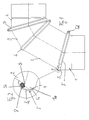
- a pipe bend is shown schematically, as typically in an exhaust pipe system can occur.
- the elbow consists of a plurality of interconnected pipes 1, 2, 3 and 4, which are preferred have a circular cross-section and in the example from one Metal, e.g. Stainless steel or aluminum.
- One of the pipes reaches into the other Tube one.
- Each of the three junctions shown in Fig. 1 is with one sealed respective sealing arrangement according to the invention.
- the adjacent tubes 1 and 2 are each with a bead Mistake.
- the bead 1a of the tube 1 can be seen in Figures 1 and 2, the end of the tube 2 with a not shown bead lies radially within the bead 1a.
- the connection needs the pipes 1 and 2 are not to be made by means of beads, the two Pipe ends of pipes 1 and 2 can e.g. also trained in this way be that the inner radius of a tube is greater than or equal to the outer radius of the other pipe, so the pipe end with the larger one Diameter pushed over the pipe end with the smaller diameter can be.
- the junction between tube 1 and tube 2 is at the end of the radially outer tube 1 directly in the area of step S. the sealing arrangement 5, 8 sealed.
- a commercially available O-ring serves as the sealing ring 8 an elastomeric material, such as rubber.
- the O-ring 8 will all around by a hood enclosing it radially from the outside Clamping band 5 fixed to step S and at the same time against the axial end of the radially outer tube 1 and pressed against the tube 2, so that all around the sealing effect of the O-ring 8 is reinforced.
- the clamping band 5 thus forms a fixing ring for fixing the sealing ring 8 in the sealing position.
- it consists of a metal, e.g. Stainless steel or aluminum.
- a force is exerted in the direction of step S, creating a force component of the O-ring 8 all the way to the axial end of the radially outer Tube 1 is generated and a force component all around the tube 2nd acts, so that the sealing effect of the connection point all around is reinforced.
- the clamping band 5 encloses like a hood the bead 1a radially from the outside, with the O-ring 8 lying away Leg 5a of the clamping band 5 on the shoulder facing away from the O-ring 8 the bead 1a comes to rest.
- the sealing arrangement 5, 8 is fixed in the axial direction. At the same time, this fixes the connection between the two Pipes 1 and 2 against loosening of the two pipes 1 and 2 from each other.
- a suitable tension of the clamping band 5 can by Friction of the sealing arrangement with the two tubes 1 and 2 additionally prevents twisting of the two tubes 1 and 2 relative to each other become.
- the clamping band 5 is in the manner of a hose clamp formed, its ends 5e, 5f in the circumferential direction to each other overlap in one area and the circumferential length of the clamping band 5 by changing the overlap area, for example via a Screw gear 5d is adjustable and fixable.
- the clamping band 5 in which a circumferential length is set, in which the clamping band 5 easily over the connection points of the pipes streaked, placed over the junction of the two pipes 1 and 2 becomes.
- the circumference of the clamping band 5 is reduced so far that the O-ring 8 and the bead 1a are enclosed like a hood, so that the O-ring 8 immediately at the axial end of the radially outer Pipe is fixed so that it is the connection point at the transition between seals the radially inner tube 2 to the radially outer tube 1 all around.
- the scope of the clamping band 5 is preferably set in this way and fixes that the clamping band 5 exerts pressure on the O-ring 8 exercises such that the sealing effect of the O-ring 8 is reinforced and that the connection between tube 1 and tube 2 in particular is fixed in such a way that twisting of the two tubes 1 and 2 against each other is prevented.
- the sealing arrangement 5, 8 a simple and effective measure for sealing and Fixing the connection point.
- the elements 5, 8 can be compared be compact and filigree, so that the sealing arrangement looks inconspicuous or pleasing from the optical design.
- sealing ring 8 with an O-ring Round cross-section was used in alternative embodiments Sealing rings with suitable other cross sections are used become.
Landscapes
- Engineering & Computer Science (AREA)
- General Engineering & Computer Science (AREA)
- Mechanical Engineering (AREA)
- Chemical & Material Sciences (AREA)
- Combustion & Propulsion (AREA)
- Joints With Sleeves (AREA)
- Gasket Seals (AREA)
Abstract
Description
Die Erfindung bezieht sich auf eine Dichtungsanordnung zur Abdichtung einer Verbindungsstelle zweier Rohre, von denen eines an der Verbindungsstelle in das andere eingreift, wobei die Dichtungsanordnung einen Dichtungsring und einen Fixierring zur Fixierung des Dichtungsrings an der Verbindungsstelle umfasst. Vorzugsweise bezieht sich die Erfindung auf eine Dichtungsanordnung zur Abdichtung der Verbindungsstelle zweier Rohre eines Abgasleitungssystems für Abgasanlagen.The invention relates to a sealing arrangement for sealing a junction of two pipes, one of which is at the junction engages in the other, the sealing arrangement having a sealing ring and a fixing ring for fixing the sealing ring on the Connection point includes. The invention preferably relates to a sealing arrangement for sealing the junction of two Pipes of an exhaust pipe system for exhaust systems.
Derartige Abgasleitungssysteme weisen oftmals eine Mehrzahl von dünnwandigen Metallrohren auf, wobei an der Verbindungsstelle zweier Rohre eines der beiden Rohre mit seinem einen Ende in das benachbarte Ende des anderen Rohrs eingeschoben ist. Die Verbindungsstelle zwischen den Rohren ist mittels einer Dichtungsanordnung der hier betrachteten Art gegen das Austreten von Rauchgasen etc., die durch das Abgasleitungssystem abgeführt werden sollen, abzudichten.Such exhaust pipe systems often have a plurality of thin-walled ones Metal pipes on, being at the junction of two pipes one of the two pipes with its one end in the adjacent end of the other tube is inserted. The junction between the Pipe is by means of a sealing arrangement of the type considered here against the escape of flue gases etc. caused by the exhaust pipe system to be dissipated to seal.
Eine Dichtungsanordnung der eingangs genannten Art ist aus der DE 200 11 766 U1 bekannt. Der Dichtungsring dieser bekannten Dichtungsanordnung weist ein Spezialprofil aus zwei über einen Verbindungsabschnitt miteinander verbundene Schenkeln zur Begrenzung einer zur Innenseite des Dichtprofilrings hin offenen Umlaufnut auf. In der Montageanordnung an der Verbindungsstelle nimmt die Umlaufnut radial nach außen gewölbte und zur Herstellung eines Formschlusses zwischen den Rohren vorgesehene Sicken auf. Als Fixierring dient eine radial außen auf dem Dichtungsring aufsitzende Schlauchfeder. A sealing arrangement of the type mentioned is from DE 200 11 766 U1 known. The sealing ring of this known sealing arrangement has a special profile of two over a connecting section interconnected legs to limit one to the inside of the sealing profile ring open circulation groove. In the assembly arrangement at the connection point the circumferential groove takes radially outwards arched and to create a positive connection between the tubes provided beads on. A radially outside on the serves as a fixing ring Sealing ring seated tube spring.
Der Erfindung liegt die Aufgabe zugrunde, eine Dichtungsanordnung der eingangs genannten Art bereitzustellen, die mit einfachen Mitteln eine wirksame Abdichtung der Verbindungsstelle ermöglicht und zuverlässig funktioniert.The invention has for its object a sealing arrangement to provide the type mentioned, which with simple means a effective sealing of the connection point enables and reliable works.
Zur Lösung der Aufgabe wird erfindungsgemäß vorgeschlagen, dass der Fixierring dazu eingerichtet ist, den Dichtungsring unmittelbar an der Endkante bzw. an dem axialen Ende des radial äußeren Rohrs so zu fixieren, dass der Dichtungsring die Verbindungsstelle am Übergang zwischen dem radial inneren Rohr zu dem radial äußeren Rohr umlaufend abdichtet.To achieve the object, the invention proposes that the Fixing ring is set up, the sealing ring directly at the end edge or to fix it at the axial end of the radially outer tube in such a way that the sealing ring is the connection point at the transition between the seals radially inner tube to the radially outer tube circumferentially.
Die Erfindung ermöglicht die Verwendung eines Dichtungsringes mit einem einfachen, unkompliziert herstellbaren Profil, beispielsweise Rundprofil, zur Abdichtung der Verbindungsstelle. Es kann sich beispielsweise um einen einfachen handelsüblichen O-Ring handeln. Ein wesentlicher Vorteil ist überdies darin zu sehen, dass der Dichtungsring die Verbindungsstelle unmittelbar im Bereich des radialen Überganges von dem inneren Rohr zu dem äußeren Rohr an der Endkante des äußeren Rohres abdichtet. Rauchgas und/oder Kondensat kann somit an der Verbindungsstelle nicht austreten. Hinzuzufügen ist noch, dass die erfindungsgemäße Dichtungsanordnung eine zuverlässige Abdichtung auch dann gewährleisten kann, wenn ein einfach zu montierender Dichtungsring mit relativ kleinem Querschnitt verwendet wird.The invention enables the use of a sealing ring with a simple, uncomplicated profile, for example round profile, for Sealing the connection point. It can be, for example act simple commercial O-ring. A major advantage is moreover it can be seen in the fact that the sealing ring is the connection point directly in the area of the radial transition from the inner tube to seals the outer tube at the end edge of the outer tube. flue gas and / or condensate cannot escape at the connection point. It should also be added that the sealing arrangement according to the invention can ensure a reliable seal even if an easy-to-install sealing ring with a relatively small cross-section is used.
In einer bevorzugten Ausgestaltung der erfindungsgemäßen Dichtungsanordnung ist der Fixierring als Klemmband mit einander in Umfangsrichtung überlappenden und im Bereich der Überlappung aneinander festgelegten Klemmbandenden ausgebildet. Die Umfangslänge des Klemmbandes sollte veränderbar einstellbar und fixierbar sein, wie dies beispielsweise von Schlauchklemmen bzw. Rohrschellen her bekannt ist. Durch Verändern der Umfangslänge des Klemmbandes kann der vom Klemmband auf den Dichtungsring ausgeübte Anpressdruck variiert werden. Ferner können derartige Klemmbänder auch in erfindungsgemäßen Dichtungsanordnungen für unterschiedliche Rohrdurchmesser verwendet werden.In a preferred embodiment of the sealing arrangement according to the invention is the fixing ring as a clamping band with each other in the circumferential direction overlapping and fixed to each other in the area of overlap Clamp band ends trained. The circumferential length of the clamping band should be changeable adjustable and fixable, as for example by Hose clamps or pipe clamps are known ago. By changing the The circumferential length of the clamping band can be that of the clamping band on the sealing ring applied contact pressure can be varied. Furthermore, such Clamping tapes also in sealing arrangements according to the invention for different pipe diameters can be used.
In einer bevorzugten Weiterbildung der erfindungsgemäßen Dichtungsanordnung kann der vorzugsweise als Klemmband ausgebildete Fixierring den Dichtungsring in der Montageanordnung umlaufend radial außen haubenartig umschließen, so dass der Dichtungsring vor äußeren, z.B. mechanischen Einflüssen geschützt ist.In a preferred development of the sealing arrangement according to the invention can the fixing ring, preferably designed as a clamping band the sealing ring in the assembly arrangement all around radially outside like a hood enclose so that the sealing ring in front of outer, e.g. mechanical Influences is protected.
Der Fixierring kann in jeder zur haubenförmigen Umfassung und zur Fixierung des Dichtungsrings geeigneten Weise ausgebildet sein, wobei der haubenartig radial nach außen gewölbte Querschnitt des Fixierrings beispielsweise die Form eines Bogens haben oder V-förmig oder U-förmig gestaltet sein kann.The fixing ring can be used for hood-shaped encirclement and fixing the sealing ring can be formed in a suitable manner, the Dome-like cross section of the fixing ring, for example, radially curved outwards have the shape of an arc or V-shape or U-shape can be designed.
Weisen die beiden Rohre im Bereich ihrer einander überlappenden Enden radial nach außen jeweils eine eine formschlüssige Verbindung gewährleistende Sicke auf, so kann in einer weiteren bevorzugten Ausbildung der Dichtungsanordnung das Klemmband die Sicken radial außen haubenartig umschließen. Ein Vorteil dieser Weiterbildung der Erfindung ist eine Stabilisierung der Verbindung der beiden Rohrenden in axialer Richtung. Darüber hinaus kann durch entsprechende Wahl der Spannung des Klemmbandes eine Fixierung der beiden Rohre gegen Verdrehung um die senkrecht zu ihrer umlaufenden Verbindung stehenden Achse erreicht werden. Ein weiterer Vorteil dieser Weiterbildung in Kombination mit der Sicke ist darin zu sehen, dass auch die Dichtungsanordnung in ihrer bestimmungsgemäßen Abdichtposition sicher fixiert ist.Point the two tubes in the area of their overlapping ends radially outward each ensure a positive connection Beading on, in a further preferred embodiment of the Sealing arrangement the clamping band the beads radially outside hood-like enclose. One advantage of this development of the invention is stabilization the connection of the two pipe ends in the axial direction. About that in addition, by appropriate choice of the tension of the clamping band a fixation of the two pipes against twisting around the perpendicular to their rotating connection axis can be reached. On Another advantage of this training in combination with the bead is in it to see that the sealing arrangement in its intended Sealing position is securely fixed.
Die vorliegende Erfindung wird im Folgenden anhand der beiliegenden Zeichnungen näher erläutert werden. Es zeigen:
- Fig. 1
- einen Rohrbogen aus mehreren miteinander verbundenen Rohren, deren Verbindungsstellen jeweils mittels einer erfindungsgemäßen Dichtungsanordnung abgedichtet sind; wobei eine der Dichtungsanordnungen bei I aufgebrochen bzw. geschnitten dargestellt ist.
- Fig. 2
- eine Darstellung eines vergrößerten Querschnitts des Details I aus Fig. 1;
- Fig. 3
- eine parallel zu einer Ringachse verlaufende Ansicht des Fixierrings der erfindungsgemäßen Dichtungsanordnung, und
- Fig. 4
- eine senkrecht zur Ringachse verlaufende Ansicht des Fixierrings der erfindungsgemäßen Dichtungsanordnung.
- Fig. 1
- a pipe bend made of several interconnected pipes, the connection points of which are each sealed by means of a sealing arrangement according to the invention; wherein one of the sealing arrangements at I is shown broken or cut.
- Fig. 2
- a representation of an enlarged cross section of detail I of Fig. 1;
- Fig. 3
- a view parallel to a ring axis of the fixing ring of the sealing arrangement according to the invention, and
- Fig. 4
- a view perpendicular to the ring axis of the fixing ring of the sealing arrangement according to the invention.
In Fig. 1 ist schematisch ein Rohrbogen gezeigt, wie er typischerweise in
einem Abgasleitungssystem vorkommen kann. Der Rohrbogen besteht aus
einer Mehrzahl miteinander verbundener Rohre 1, 2, 3 und 4, die bevorzugt
einen kreisrunden Querschnitt aufweisen und im Beispielsfall aus einem
Metall, z.B. Edelstahl oder Aluminium, bestehen. An einer Verbindungsstelle
von jeweils zwei Rohren greift jeweils eines der Rohre in das andere
Rohr ein. Jede der drei in Fig. 1 gezeigten Verbindungsstellen ist mit einer
jeweiligen erfindungsgemäßen Dichtungsanordnung abgedichtet. Im Folgenden
wird die Verbindungsstelle der Rohre 1 und 2 und deren Abdichtung
als Beispiel im Detail beschrieben.In Fig. 1, a pipe bend is shown schematically, as typically in
an exhaust pipe system can occur. The elbow consists of
a plurality of interconnected
Die einander benachbarten Rohre 1 und 2 sind jeweils mit einer Sicke
versehen. Die Sicke 1a des Rohres 1 ist in den Figuren 1 und 2 erkennbar,
wobei das Ende des Rohrs 2 mit einer nicht dargestellten Sicke formschlüssig
radial innerhalb der Sicke 1a liegt. Allerdings braucht die Verbindung
der Rohre 1 und 2 nicht grundsätzlich mittels Sicken zu erfolgen, die beiden
Rohrenden der Rohre 1 und 2 können z.B. auch derart ausgebildet
sein, dass der Innenradius des einen Rohres größer oder gleich dem Außenradius
des anderen Rohres ist, so dass das Rohrende mit dem größeren
Durchmesser über das Rohrende mit dem kleineren Durchmesser geschoben
werden kann.The
Die Verbindungsstelle zwischen dem Rohr 1 und dem Rohr 2 wird am Ende
des radial außen liegenden Rohrs 1 unmittelbar im Bereich der Stufe S mit
der erfindungsgemäßen Dichtungsanordnung 5, 8 abgedichtet.The junction between
Als Dichtungsring 8 dient im Beispielsfall ein handelsüblicher O-Ring aus
einem elastomeren Material, beispielsweise Gummi. Der O-Ring 8 wird
umlaufend durch ein ihn von radial außen haubenartig umschließendes
Klemmband 5 an der Stufe S fixiert und gleichzeitig gegen das axiale Ende
des radial äußeren Rohres 1 sowie gegen das Rohr 2 gedrückt, so dass
umlaufend die Abdichtwirkung des O-Rings 8 verstärkt wird. Das Klemmband
5 bildet somit einen Fixierring zur Fixierung des Dichtungsringes 8 in
der Dichtungsposition. Es besteht im Beispielsfall aus einem Metall, z.B.
Edelstahl oder Aluminium.In the example, a commercially available O-ring serves as the
Der haubenartige Querschnitt des Klemmbands 5 wird, wie in Fig. 2 gezeigt,
durch zwei Schenkel 5a und 5b gebildet, die über einen Verbindungsabschnitt
5c miteinander verbunden sind und die vom Verbindungsabschnitt
5c aus radial nach innen verlaufen. Im vorliegenden Ausführungsbeispiel
wird dabei durch den Schenkel 5b umlaufend auf den O-Ring 8
eine Kraft in Richtung der Stufe S ausgeübt, wodurch eine Kraftkomponente
des O-Rings 8 umlaufend auf das axiale Ende des radial äußeren
Rohrs 1 erzeugt wird und eine Kraftkomponente umlaufend auf das Rohr 2
wirkt, so dass umlaufend die Abdichtungswirkung der Verbindungsstelle
verstärkt wird.The hood-like cross section of the
Wie in Fig. 2 dargestellt, umschließt das Klemmband 5 haubenartig auch
die Sicke 1a radial von außen, wobei der dem O-Ring 8 entfernt liegende
Schenkel 5a des Klemmbands 5 an der dem O-Ring 8 abgewandten Schulter
der Sicke 1a zu liegen kommt. Durch das Anliegen des Schenkels 5a an
der Sicke 1a und durch das Anliegen des anderen Schenkels 5b an dem 0-Ring
8 erfolgt eine Fixierung der Dichtungsanordnung 5, 8 in axialer Richtung.
Gleichzeitig erfolgt dadurch eine Fixierung der Verbindung der beiden
Rohre 1 und 2 gegen ein Lösen der beiden Rohre 1 und 2 voneinander.
Durch die Wahl einer geeigneten Spannung des Klemmbands 5 kann durch
Reibschluss der Dichtungsanordnung mit den beiden Rohren 1 und 2 zusätzlich
ein Verdrehen der beiden Rohre 1 und 2 relativ zueinander verhindert
werden.As shown in Fig. 2, the
Wie in Fig. 3 dargestellt, ist das Klemmband 5 in der Art einer Schlauchschelle
ausgebildet, wobei seine Enden 5e, 5f in Umfangsrichtung einander
in einem Bereich überlappen und wobei die Umfangslänge des Klemmbands
5 durch Veränderung des Überlappungsbereichs zum Beispiel über ein
Schraubengetriebe 5d veränderbar einstellbar und fixierbar ist.As shown in Fig. 3, the
Bei der Montage der Dichtungsanordnung 5, 8 kann in einem ersten Schritt
der O-Ring 8 am Ende des radial außen liegenden Rohrs 1 der bereits
verbundenen Rohre 1 und 2 an die Verbindungsstelle angelegt werden,
wobei dann das Klemmband 5, bei dem eine Umfangslänge eingestellt ist,
bei der sich das Klemmband 5 leicht über die Verbindungsstellen der Rohre
streifen lässt, über die Verbindungsstelle der beiden Rohre 1 und 2 gelegt
wird. Nach der Positionierung des Klemmbands 5 an der vorgesehenen
Verbindungsstelle wird der Umfang des Klemmbands 5 so weit verringert,
dass der O-Ring 8 und die Sicke 1a haubenartig umschlossen werden, so
dass der O-Ring 8 unmittelbar an dem axialen Ende des radial äußeren
Rohrs so fixiert wird, dass er die Verbindungsstelle am Übergang zwischen
dem radial inneren Rohr 2 zu dem radial äußeren Rohr 1 umlaufend abdichtet.
Der Umfang des Klemmbands 5 wird dabei vorzugsweise so eingestellt
und fixiert, dass das Klemmband 5 einen Druck auf den O-Ring 8
ausübt, derart, dass die Dichtwirkung des O-Rings 8 verstärkt wird und
dass die Verbindung zwischen dem Rohr 1 und dem Rohr 2 insbesondere
in der Weise fixiert wird, dass eine Verdrehung der beiden Rohre 1 und 2
gegeneinander verhindert wird.In the assembly of the
Wie in den Figuren dargestellt und oben erläutert, stellt die Dichtungsanordnung
5, 8 eine einfache und wirksame Maßnahme zur Abdichtung und
Fixierung der Verbindungsstelle dar. Die Elemente 5, 8 können vergleichsweise
kompakt und filigran ausgebildet sein, so dass die Dichtungsanordnung
von der optischen Gestaltung her unauffällig bzw. gefällig aussieht.As shown in the figures and explained above, the sealing
Wenngleich im Ausführungsbeispiel als Dichtungsring 8 ein O-Ring mit
Rundquerschnitt herangezogen wurde, können in alternativen Ausführungsbeispielen
Dichtungsringe mit geeigneten anderen Querschnitten verwendet
werden.Although in the embodiment as a
Claims (11)
dadurch gekennzeichnet, dass der Fixierring (5) dazu eingerichtet ist, den Dichtungsring (8) unmittelbar an der Endkante des radial äußeren Rohrs (1) so zu fixieren, dass der Dichtungsring (8) die Verbindungsstelle am Übergang zwischen dem radial inneren Rohr (2) zu dem radial äußeren Rohr (1) umlaufend abdichtet.Sealing arrangement for sealing a connection point of two pipes (1, 2), one of which (2) engages in the other (1) at the connection point, the sealing arrangement comprising a sealing ring (8) and a fixing ring (5) for fixing the sealing ring (8 ) at the junction,
characterized in that the fixing ring (5) is set up to fix the sealing ring (8) directly at the end edge of the radially outer tube (1) in such a way that the sealing ring (8) the connection point at the transition between the radially inner tube (2 ) seals all around to the radially outer tube (1).
Applications Claiming Priority (2)
| Application Number | Priority Date | Filing Date | Title |
|---|---|---|---|
| DE20105012U | 2001-03-22 | ||
| DE20105012U DE20105012U1 (en) | 2001-03-22 | 2001-03-22 | Sealing arrangement for sealing a connection point of two interconnected pipes |
Publications (3)
| Publication Number | Publication Date |
|---|---|
| EP1243855A2 true EP1243855A2 (en) | 2002-09-25 |
| EP1243855A3 EP1243855A3 (en) | 2003-10-08 |
| EP1243855B1 EP1243855B1 (en) | 2007-09-26 |
Family
ID=7954698
Family Applications (1)
| Application Number | Title | Priority Date | Filing Date |
|---|---|---|---|
| EP02005680A Expired - Lifetime EP1243855B1 (en) | 2001-03-22 | 2002-03-12 | Sealing arrangement for the connection of two pipes |
Country Status (3)
| Country | Link |
|---|---|
| EP (1) | EP1243855B1 (en) |
| AT (1) | ATE374342T1 (en) |
| DE (2) | DE20105012U1 (en) |
Citations (6)
| Publication number | Priority date | Publication date | Assignee | Title |
|---|---|---|---|---|
| US2269664A (en) * | 1941-03-14 | 1942-01-13 | United Specialties Co | Seal construction |
| DE868542C (en) * | 1941-02-09 | 1953-02-26 | Westdeutsche Mannesmannroehren | Socket pipe connection |
| US3913955A (en) * | 1973-07-05 | 1975-10-21 | Deere & Co | Sealed coupling for exhaust pipe sections |
| DE3509774A1 (en) * | 1985-03-19 | 1986-10-02 | Witzenmann GmbH, Metallschlauch-Fabrik Pforzheim, 7530 Pforzheim | Pipe connection |
| EP0546893A1 (en) * | 1991-12-13 | 1993-06-16 | Daniel Urion | Segment/exhaust fume conduit with double push-in sleeve |
| EP1223375A1 (en) * | 2001-01-08 | 2002-07-17 | Bluetech Holding S.A. | Sealing ring for modular ducts and modular duct incorporating said ring |
-
2001
- 2001-03-22 DE DE20105012U patent/DE20105012U1/en not_active Expired - Lifetime
-
2002
- 2002-03-12 EP EP02005680A patent/EP1243855B1/en not_active Expired - Lifetime
- 2002-03-12 AT AT02005680T patent/ATE374342T1/en not_active IP Right Cessation
- 2002-03-12 DE DE50210949T patent/DE50210949D1/en not_active Expired - Lifetime
Patent Citations (6)
| Publication number | Priority date | Publication date | Assignee | Title |
|---|---|---|---|---|
| DE868542C (en) * | 1941-02-09 | 1953-02-26 | Westdeutsche Mannesmannroehren | Socket pipe connection |
| US2269664A (en) * | 1941-03-14 | 1942-01-13 | United Specialties Co | Seal construction |
| US3913955A (en) * | 1973-07-05 | 1975-10-21 | Deere & Co | Sealed coupling for exhaust pipe sections |
| DE3509774A1 (en) * | 1985-03-19 | 1986-10-02 | Witzenmann GmbH, Metallschlauch-Fabrik Pforzheim, 7530 Pforzheim | Pipe connection |
| EP0546893A1 (en) * | 1991-12-13 | 1993-06-16 | Daniel Urion | Segment/exhaust fume conduit with double push-in sleeve |
| EP1223375A1 (en) * | 2001-01-08 | 2002-07-17 | Bluetech Holding S.A. | Sealing ring for modular ducts and modular duct incorporating said ring |
Also Published As
| Publication number | Publication date |
|---|---|
| EP1243855B1 (en) | 2007-09-26 |
| DE50210949D1 (en) | 2007-11-08 |
| EP1243855A3 (en) | 2003-10-08 |
| ATE374342T1 (en) | 2007-10-15 |
| DE20105012U1 (en) | 2001-09-13 |
Similar Documents
| Publication | Publication Date | Title |
|---|---|---|
| DE69825637T2 (en) | Sealing ring for tubular element | |
| DE2518001C2 (en) | Pipe seal for sealing between two pipe ends that can be joined together | |
| DE60320226T2 (en) | ANCHORING DEVICE FOR PIPE COUPLING | |
| EP0432436B1 (en) | Flexible pipe component for exhaust conduits of internal combustion engines used on vehicles | |
| DE3339169A1 (en) | CONNECTOR TO CONNECT THE END OF TWO TUBES | |
| DE3541194A1 (en) | PIPE CLAMPING DEVICE | |
| EP0769648B1 (en) | Hose clip | |
| DE3926626A1 (en) | Pipe coupling for two pipe ends - includes annular elastomer sleeve with thermal insulating layer | |
| DE102017121994A1 (en) | Clamp with sealing element | |
| DD298542A5 (en) | PIPE COUPLING | |
| DE2922403A1 (en) | PIPE CONNECTION | |
| DE19542463B4 (en) | pipe coupling | |
| EP0897505B1 (en) | Pipe coupling | |
| EP1243855B1 (en) | Sealing arrangement for the connection of two pipes | |
| DE102006029242B4 (en) | flange | |
| DE19735261C1 (en) | Connector for plastics pipes | |
| DE4103702C1 (en) | ||
| DE102012005943A1 (en) | Device for connecting e.g. plastic pipes with different outer diameters in e.g. drainage application, has elements counteracting change of clearance of wall breakthroughs in circumferential direction and associated to wall breakthroughs | |
| EP0498322B1 (en) | Device for the sealed connection of the smoothed cylindrical ends of two pipes | |
| DE2634349C2 (en) | Pipe connection | |
| DE102009033247B3 (en) | Clutch with notches | |
| DE60205661T2 (en) | Device for the tight coupling of two rigid tubes of the same diameter | |
| DE3246136C1 (en) | Pipe coupling | |
| DE102013015895B4 (en) | Press fitting and connection arrangement with such a press fitting | |
| EP3401584B1 (en) | Pipe, in particular exhaust pipe |
Legal Events
| Date | Code | Title | Description |
|---|---|---|---|
| PUAI | Public reference made under article 153(3) epc to a published international application that has entered the european phase |
Free format text: ORIGINAL CODE: 0009012 |
|
| AK | Designated contracting states |
Kind code of ref document: A2 Designated state(s): AT BE CH CY DE DK ES FI FR GB GR IE IT LI LU MC NL PT SE TR |
|
| AX | Request for extension of the european patent |
Free format text: AL;LT;LV;MK;RO;SI |
|
| PUAL | Search report despatched |
Free format text: ORIGINAL CODE: 0009013 |
|
| AK | Designated contracting states |
Kind code of ref document: A3 Designated state(s): AT BE CH CY DE DK ES FI FR GB GR IE IT LI LU MC NL PT SE TR |
|
| AX | Request for extension of the european patent |
Extension state: AL LT LV MK RO SI |
|
| 17P | Request for examination filed |
Effective date: 20040310 |
|
| AKX | Designation fees paid |
Designated state(s): AT BE CH CY DE DK ES FI FR GB GR IE IT LI LU MC NL PT SE TR |
|
| RAP1 | Party data changed (applicant data changed or rights of an application transferred) |
Owner name: KUTZNER + WEBER GMBH |
|
| 17Q | First examination report despatched |
Effective date: 20060308 |
|
| GRAP | Despatch of communication of intention to grant a patent |
Free format text: ORIGINAL CODE: EPIDOSNIGR1 |
|
| GRAS | Grant fee paid |
Free format text: ORIGINAL CODE: EPIDOSNIGR3 |
|
| GRAA | (expected) grant |
Free format text: ORIGINAL CODE: 0009210 |
|
| AK | Designated contracting states |
Kind code of ref document: B1 Designated state(s): AT BE CH CY DE DK ES FI FR GB GR IE IT LI LU MC NL PT SE TR |
|
| REG | Reference to a national code |
Ref country code: GB Ref legal event code: FG4D Free format text: NOT ENGLISH |
|
| REG | Reference to a national code |
Ref country code: CH Ref legal event code: EP |
|
| REG | Reference to a national code |
Ref country code: CH Ref legal event code: NV Representative=s name: A. BRAUN, BRAUN, HERITIER, ESCHMANN AG PATENTANWAE |
|
| REF | Corresponds to: |
Ref document number: 50210949 Country of ref document: DE Date of ref document: 20071108 Kind code of ref document: P |
|
| REG | Reference to a national code |
Ref country code: IE Ref legal event code: FG4D Free format text: LANGUAGE OF EP DOCUMENT: GERMAN |
|
| GBT | Gb: translation of ep patent filed (gb section 77(6)(a)/1977) |
Effective date: 20071204 |
|
| PG25 | Lapsed in a contracting state [announced via postgrant information from national office to epo] |
Ref country code: FI Free format text: LAPSE BECAUSE OF FAILURE TO SUBMIT A TRANSLATION OF THE DESCRIPTION OR TO PAY THE FEE WITHIN THE PRESCRIBED TIME-LIMIT Effective date: 20070926 |
|
| ET | Fr: translation filed | ||
| PG25 | Lapsed in a contracting state [announced via postgrant information from national office to epo] |
Ref country code: ES Free format text: LAPSE BECAUSE OF FAILURE TO SUBMIT A TRANSLATION OF THE DESCRIPTION OR TO PAY THE FEE WITHIN THE PRESCRIBED TIME-LIMIT Effective date: 20080106 Ref country code: GR Free format text: LAPSE BECAUSE OF FAILURE TO SUBMIT A TRANSLATION OF THE DESCRIPTION OR TO PAY THE FEE WITHIN THE PRESCRIBED TIME-LIMIT Effective date: 20071227 |
|
| REG | Reference to a national code |
Ref country code: IE Ref legal event code: FD4D |
|
| PG25 | Lapsed in a contracting state [announced via postgrant information from national office to epo] |
Ref country code: PT Free format text: LAPSE BECAUSE OF FAILURE TO SUBMIT A TRANSLATION OF THE DESCRIPTION OR TO PAY THE FEE WITHIN THE PRESCRIBED TIME-LIMIT Effective date: 20080226 |
|
| REG | Reference to a national code |
Ref country code: CH Ref legal event code: PFA Owner name: KUTZNER + WEBER GMBH Free format text: KUTZNER + WEBER GMBH#FRAUENSTRASSE 32#82216 MAISACH (DE) -TRANSFER TO- KUTZNER + WEBER GMBH#FRAUENSTRASSE 32#82216 MAISACH (DE) |
|
| PG25 | Lapsed in a contracting state [announced via postgrant information from national office to epo] |
Ref country code: SE Free format text: LAPSE BECAUSE OF FAILURE TO SUBMIT A TRANSLATION OF THE DESCRIPTION OR TO PAY THE FEE WITHIN THE PRESCRIBED TIME-LIMIT Effective date: 20071226 |
|
| PG25 | Lapsed in a contracting state [announced via postgrant information from national office to epo] |
Ref country code: DK Free format text: LAPSE BECAUSE OF FAILURE TO SUBMIT A TRANSLATION OF THE DESCRIPTION OR TO PAY THE FEE WITHIN THE PRESCRIBED TIME-LIMIT Effective date: 20070926 |
|
| PLBE | No opposition filed within time limit |
Free format text: ORIGINAL CODE: 0009261 |
|
| STAA | Information on the status of an ep patent application or granted ep patent |
Free format text: STATUS: NO OPPOSITION FILED WITHIN TIME LIMIT |
|
| 26N | No opposition filed |
Effective date: 20080627 |
|
| PG25 | Lapsed in a contracting state [announced via postgrant information from national office to epo] |
Ref country code: IE Free format text: LAPSE BECAUSE OF FAILURE TO SUBMIT A TRANSLATION OF THE DESCRIPTION OR TO PAY THE FEE WITHIN THE PRESCRIBED TIME-LIMIT Effective date: 20070926 Ref country code: MC Free format text: LAPSE BECAUSE OF NON-PAYMENT OF DUE FEES Effective date: 20080331 |
|
| PG25 | Lapsed in a contracting state [announced via postgrant information from national office to epo] |
Ref country code: CY Free format text: LAPSE BECAUSE OF FAILURE TO SUBMIT A TRANSLATION OF THE DESCRIPTION OR TO PAY THE FEE WITHIN THE PRESCRIBED TIME-LIMIT Effective date: 20070926 |
|
| PGFP | Annual fee paid to national office [announced via postgrant information from national office to epo] |
Ref country code: FR Payment date: 20100402 Year of fee payment: 9 |
|
| PGFP | Annual fee paid to national office [announced via postgrant information from national office to epo] |
Ref country code: AT Payment date: 20100311 Year of fee payment: 9 Ref country code: GB Payment date: 20100322 Year of fee payment: 9 |
|
| PG25 | Lapsed in a contracting state [announced via postgrant information from national office to epo] |
Ref country code: LU Free format text: LAPSE BECAUSE OF NON-PAYMENT OF DUE FEES Effective date: 20080312 |
|
| PG25 | Lapsed in a contracting state [announced via postgrant information from national office to epo] |
Ref country code: TR Free format text: LAPSE BECAUSE OF FAILURE TO SUBMIT A TRANSLATION OF THE DESCRIPTION OR TO PAY THE FEE WITHIN THE PRESCRIBED TIME-LIMIT Effective date: 20070926 |
|
| PGFP | Annual fee paid to national office [announced via postgrant information from national office to epo] |
Ref country code: IT Payment date: 20100326 Year of fee payment: 9 Ref country code: NL Payment date: 20100325 Year of fee payment: 9 |
|
| PGFP | Annual fee paid to national office [announced via postgrant information from national office to epo] |
Ref country code: BE Payment date: 20100506 Year of fee payment: 9 |
|
| PGFP | Annual fee paid to national office [announced via postgrant information from national office to epo] |
Ref country code: CH Payment date: 20110324 Year of fee payment: 10 |
|
| PGFP | Annual fee paid to national office [announced via postgrant information from national office to epo] |
Ref country code: DE Payment date: 20101231 Year of fee payment: 10 |
|
| BERE | Be: lapsed |
Owner name: KUTZNER + WEBER G.M.B.H. Effective date: 20110331 |
|
| REG | Reference to a national code |
Ref country code: NL Ref legal event code: V1 Effective date: 20111001 |
|
| GBPC | Gb: european patent ceased through non-payment of renewal fee |
Effective date: 20110312 |
|
| PG25 | Lapsed in a contracting state [announced via postgrant information from national office to epo] |
Ref country code: AT Free format text: LAPSE BECAUSE OF NON-PAYMENT OF DUE FEES Effective date: 20110312 |
|
| REG | Reference to a national code |
Ref country code: FR Ref legal event code: ST Effective date: 20111130 |
|
| PG25 | Lapsed in a contracting state [announced via postgrant information from national office to epo] |
Ref country code: BE Free format text: LAPSE BECAUSE OF NON-PAYMENT OF DUE FEES Effective date: 20110331 |
|
| PG25 | Lapsed in a contracting state [announced via postgrant information from national office to epo] |
Ref country code: NL Free format text: LAPSE BECAUSE OF NON-PAYMENT OF DUE FEES Effective date: 20111001 Ref country code: FR Free format text: LAPSE BECAUSE OF NON-PAYMENT OF DUE FEES Effective date: 20110331 |
|
| PG25 | Lapsed in a contracting state [announced via postgrant information from national office to epo] |
Ref country code: GB Free format text: LAPSE BECAUSE OF NON-PAYMENT OF DUE FEES Effective date: 20110312 Ref country code: IT Free format text: LAPSE BECAUSE OF NON-PAYMENT OF DUE FEES Effective date: 20110312 |
|
| REG | Reference to a national code |
Ref country code: CH Ref legal event code: PL |
|
| PG25 | Lapsed in a contracting state [announced via postgrant information from national office to epo] |
Ref country code: CH Free format text: LAPSE BECAUSE OF NON-PAYMENT OF DUE FEES Effective date: 20120331 Ref country code: LI Free format text: LAPSE BECAUSE OF NON-PAYMENT OF DUE FEES Effective date: 20120331 |
|
| REG | Reference to a national code |
Ref country code: DE Ref legal event code: R119 Ref document number: 50210949 Country of ref document: DE Effective date: 20121002 |
|
| PG25 | Lapsed in a contracting state [announced via postgrant information from national office to epo] |
Ref country code: DE Free format text: LAPSE BECAUSE OF NON-PAYMENT OF DUE FEES Effective date: 20121002 |