EP1243817B1 - Continuously variable transmission having an accurate pressure control system - Google Patents
Continuously variable transmission having an accurate pressure control system Download PDFInfo
- Publication number
- EP1243817B1 EP1243817B1 EP20010201087 EP01201087A EP1243817B1 EP 1243817 B1 EP1243817 B1 EP 1243817B1 EP 20010201087 EP20010201087 EP 20010201087 EP 01201087 A EP01201087 A EP 01201087A EP 1243817 B1 EP1243817 B1 EP 1243817B1
- Authority
- EP
- European Patent Office
- Prior art keywords
- pressure
- valve
- hydraulic circuit
- flow
- medium
- Prior art date
- Legal status (The legal status is an assumption and is not a legal conclusion. Google has not performed a legal analysis and makes no representation as to the accuracy of the status listed.)
- Expired - Lifetime
Links
- 230000005540 biological transmission Effects 0.000 title claims abstract description 96
- 230000001419 dependent effect Effects 0.000 claims description 6
- 238000000034 method Methods 0.000 claims description 6
- 230000008569 process Effects 0.000 claims description 6
- 230000008901 benefit Effects 0.000 description 15
- 230000008859 change Effects 0.000 description 8
- 238000010276 construction Methods 0.000 description 7
- 230000000694 effects Effects 0.000 description 4
- 230000006872 improvement Effects 0.000 description 3
- 238000012546 transfer Methods 0.000 description 3
- 230000001133 acceleration Effects 0.000 description 2
- 230000007423 decrease Effects 0.000 description 2
- 230000003247 decreasing effect Effects 0.000 description 2
- 238000013461 design Methods 0.000 description 2
- 238000013178 mathematical model Methods 0.000 description 2
- 230000004043 responsiveness Effects 0.000 description 2
- 230000006978 adaptation Effects 0.000 description 1
- 238000011161 development Methods 0.000 description 1
- 230000003993 interaction Effects 0.000 description 1
- 238000005461 lubrication Methods 0.000 description 1
- 238000012986 modification Methods 0.000 description 1
- 230000004048 modification Effects 0.000 description 1
- 238000000926 separation method Methods 0.000 description 1
- 230000007704 transition Effects 0.000 description 1
Images


Classifications
-
- F—MECHANICAL ENGINEERING; LIGHTING; HEATING; WEAPONS; BLASTING
- F16—ENGINEERING ELEMENTS AND UNITS; GENERAL MEASURES FOR PRODUCING AND MAINTAINING EFFECTIVE FUNCTIONING OF MACHINES OR INSTALLATIONS; THERMAL INSULATION IN GENERAL
- F16H—GEARING
- F16H9/00—Gearings for conveying rotary motion with variable gear ratio, or for reversing rotary motion, by endless flexible members
-
- F—MECHANICAL ENGINEERING; LIGHTING; HEATING; WEAPONS; BLASTING
- F16—ENGINEERING ELEMENTS AND UNITS; GENERAL MEASURES FOR PRODUCING AND MAINTAINING EFFECTIVE FUNCTIONING OF MACHINES OR INSTALLATIONS; THERMAL INSULATION IN GENERAL
- F16H—GEARING
- F16H61/00—Control functions within control units of change-speed- or reversing-gearings for conveying rotary motion ; Control of exclusively fluid gearing, friction gearing, gearings with endless flexible members or other particular types of gearing
- F16H61/02—Control functions within control units of change-speed- or reversing-gearings for conveying rotary motion ; Control of exclusively fluid gearing, friction gearing, gearings with endless flexible members or other particular types of gearing characterised by the signals used
- F16H61/0202—Control functions within control units of change-speed- or reversing-gearings for conveying rotary motion ; Control of exclusively fluid gearing, friction gearing, gearings with endless flexible members or other particular types of gearing characterised by the signals used the signals being electric
- F16H61/0204—Control functions within control units of change-speed- or reversing-gearings for conveying rotary motion ; Control of exclusively fluid gearing, friction gearing, gearings with endless flexible members or other particular types of gearing characterised by the signals used the signals being electric for gearshift control, e.g. control functions for performing shifting or generation of shift signal
- F16H61/0206—Layout of electro-hydraulic control circuits, e.g. arrangement of valves
-
- F—MECHANICAL ENGINEERING; LIGHTING; HEATING; WEAPONS; BLASTING
- F16—ENGINEERING ELEMENTS AND UNITS; GENERAL MEASURES FOR PRODUCING AND MAINTAINING EFFECTIVE FUNCTIONING OF MACHINES OR INSTALLATIONS; THERMAL INSULATION IN GENERAL
- F16H—GEARING
- F16H61/00—Control functions within control units of change-speed- or reversing-gearings for conveying rotary motion ; Control of exclusively fluid gearing, friction gearing, gearings with endless flexible members or other particular types of gearing
- F16H61/66—Control functions within control units of change-speed- or reversing-gearings for conveying rotary motion ; Control of exclusively fluid gearing, friction gearing, gearings with endless flexible members or other particular types of gearing specially adapted for continuously variable gearings
- F16H61/662—Control functions within control units of change-speed- or reversing-gearings for conveying rotary motion ; Control of exclusively fluid gearing, friction gearing, gearings with endless flexible members or other particular types of gearing specially adapted for continuously variable gearings with endless flexible members
- F16H61/66272—Control functions within control units of change-speed- or reversing-gearings for conveying rotary motion ; Control of exclusively fluid gearing, friction gearing, gearings with endless flexible members or other particular types of gearing specially adapted for continuously variable gearings with endless flexible members characterised by means for controlling the torque transmitting capability of the gearing
Landscapes
- Engineering & Computer Science (AREA)
- General Engineering & Computer Science (AREA)
- Mechanical Engineering (AREA)
- Control Of Transmission Device (AREA)
- Transmissions By Endless Flexible Members (AREA)
Abstract
Description
- The present invention relates to a continuously variable transmission according to the preamble of
claim 1. Such a transmission is known from DE-A-195 19 163. The known transmission comprises a first rotatable disc pair, at least one of the discs thereof being axially displaceable under the influence of a first pressure in a first medium chamber of a piston-cylinder assembly associated with the said first disc pair, a second rotatable disc pair, at least one of the discs thereof being axially displaceable under the influence of a second pressure in a second medium chamber of a piston-cylinder assembly associated with the said second disc pair, a drive belt running around said disc pairs at variable running radii defining a transmission ratio of the transmission, and a hydraulic control system coupled to the said medium chambers for influencing the hydraulic pressures therein. - The present invention further relates to the use of such a continuously variable transmission for performing a traction process in a vehicle or to a mechanical load process in an aeroplane or ship, in particular to a mechanical load process where an engine drives the said first disc pair at a variable rotational speed and a load is driven by the said second disc pair at an essentially constant rotational speed, wherein the load may be a constant frequency electrical generator.
- The known control system is provided with a pressure valve for controlling the second pressure that prevails in a second hydraulic circuit comprising the said second medium chamber and to which second hydraulic circuit a pump is attached for supplying the control system with a flow of medium, i.e. the so called pump flow, and a flow valve for influencing the first pressure that prevails in a first hydraulic circuit comprising the said first medium chamber by allowing a flow of medium either from second hydraulic circuit to the first hydraulic circuit, or from the first hydraulic circuit to a medium sink or reservoir, or no flow at all. The pressure level of each of the first pressure and the second pressure in combination with an active surface area of the respective medium chamber determines a clamping force that is exerted by the respective disc pair on a part of the drive belt running between the discs thereof. These clamping forces allow a transfer of torque between a disc pair and the belt through friction and, moreover, influence the transmission ratio. Since this construction only allows the first pressure to become equal to or smaller than the second pressure, the active surface area of the first medium chamber is made larger than that of the second medium chamber so as to still allow the clamping force exerted by the first disc pair to become larger than that of the second disc pair. In known transmission designs the ratio between the said active surface areas to this end varies between about 1.8 and 2.5.
- This pressure control system according to the known art has the disadvantage that its range of applications is limited. In particular it appeared in practice that an accurate adjustment of small amounts of medium flow from the second hydraulic circuit through the flow valve to the first hydraulic circuit, which are required during regularly occurring steady state transmission conditions wherein the transmission ratio is to be maintained constant, is hardly possible with the aid of the known control system at least with a desired degree of accuracy.
- It is remarked that form the German patent application No. 195 19 163 there is known a control system provided with a hydraulic circuit having a alternative layout. The system is intended and suited for fail safe operation of the transmission, i.e. without using electronically controlled valves. In this system the second hydraulic circuit and the first hydraulic circuit are arranged in series with respect to the medium flow supplied into the second hydraulic circuit by a source thereof, such as e.g. the said pump, and wherein a first valve is situated between the said first and second hydraulic circuits, which valve is suited for and capable of affecting a flow of medium from the second circuit to the first circuit such that a flow dependent pressure difference may be effected between the said first and second pressures. In this control system a relatively large flow of medium passes through the first valve. In steady state transmission conditions the entire medium flow supplied into the second hydraulic circuit flows through the first valve and during a shifting of the transmission ratio the flow through the first valve will be somewhat elevated or decreased because of the accompanying change of the volume of the second medium chamber. It is noted that leakage of the medium in particular from the pressure chambers to the environment is considered negligible. A second valve suited for and capable of affecting a flow of medium from the first hydraulic circuit to the medium sink, whereby the first pressure is set. This control system provides only one medium sink connection, instead of two as in the previously discussed system. This reduces the flow of waist medium and in addition decreases the loss of energy, which energy is included in pressurised medium.
- In this latter known system the first valve directly sets the pressure in the second medium chamber and the second valve directly sets the pressure in the first medium chamber. According to the invention, however, an improved controllability is advantageously realised in the continuously variable transmission that is characterised according to
claim 1. - The transmission according to the present invention is provided with a control system, wherein the second valve, although directly affecting the first pressure, is in fact used to control the second pressure. Such pressure control may be performed using a known valve control system wherein a valve setting is influenced in dependence on a hydraulic or electronic signal that represents the difference between an actual, i.e. measured, pressure, and a desired pressure. Such a valve control system is well known and is e.g. described in EP-B-0.451.887. Preferably, the construction of the second valve conforms to that of the known pressure valve.
- This pressure control arrangement wherein the pressure valve is located between the first hydraulic circuit and the medium sink has the advantage that when the second pressure changes, i.e. increases or decreases, the first pressure has the tendency to change accordingly. Thereby the ratio between said pressures advantageously changes only slightly, if at all, as does the transmission ratio, which varies in dependency on such pressure ratio. This has the significant advantage that when the pressure levels are changed, e.g. as a result of a change in the torque level to be transferred, no large adaptations of the control system and in particular of the first valve are required to maintain a constant transmission ratio. Such control behaviour is considered desirable, since this means that the mutual interaction of transmission ratio control and belt-disc friction control, which would complicate and destabilise the controllability thereof, is reduced improving the responsiveness of the system and yielding a stable and accurate transmission control.
- Yet a further significant advantage of this latter pressure control system according to the invention is revealed when the transmission is at stand still, i.e. when the disc pairs are not rotating and may be understand as follows. In many known control systems only a single pressure sensor is adopted to save cost. This usually means that the second pressure is controlled by minimising the difference between a pressure level measured by means of the said pressure sensor and a desired pressure level, whereas the first pressure is controlled indirectly by allowing the first pressure to change in a direction that changes the actual transmission ratio towards a desired transmission ratio. Moreover, the first pressure level may be calculated from the measured transmission ratio and the second pressure level by using a mathematical model of the transmission such as the IDE-model, which is relatively well known in the art. However, at standstill of the transmission when the disc pairs and the belt are not rotating, the actual transmission ratio can usually not be determined and, moreover, the known mathematical models are invalid. It follows that in this situation the known control system will not be able to adequately control the first pressure, particularly because for the flow valve there is no fixed relation between a hydraulic or electronic control signal for influencing the setting of the flow valve and the level first pressure actually set. In these circumstances the first pressure may unwittingly become too low to prevent mutual slip of the belt and the first disc pair. This may disadvantageously result in a loss of transmission efficiency and wear of the drive belt. With the arrangement according to the invention this problem is overcome by the fact that the second pressure is measured by the said sensor, whereas the pressure valve, which is controlled based on this measured pressure, is situated between the first hydraulic circuit and the medium sink. This means that during standstill the level of both the second pressure and the first pressure are relatively accurately known. The second pressure is known, because it may be measured by means of the pressure sensor, whereas the first pressure may be accurately approximated or estimated, because the control characteristic of the pressure valve that sets this pressure shows a relatively accurate predetermined relation between a hydraulic or electronic control signal for influencing the setting of the pressure control valve and the level of the first pressure actually set by the said valve. So ultimately a speedy and reliable fine tuning of the transmission ratio and corresponding transmission parameters is now possible at standstill, whereby the first pressure is being controlled directly, namely by the pressure control valve. Accordingly, the invention also relates a control system incorporating a pressure sensor for determining the medium pressure prevailing in the second circuit and a pressure valve for controlling the first pressure having a control characteristic that shows a predetermined relation between a control signal for influencing the setting of the pressure valve and the level of the pressure actually set by the valve.
- As a consequence of the aforementioned advantages application possibilities of the continuously variable transmission according to the invention have been extended, such that the system can now also be used effectively for Constant Speed Drive (CSD) applications. Such CSD applications occur when driving electrical generators, such as on board of air planes and are characterised by the feature that the speed of the generator and thus the transmission ratio is to be controlled within narrow constraints. Moreover, the control system maintains the advantage of the prior art control system, wherein the first pressure is equal to or lower than the second pressure, over other systems, such as are e.g. known from US-6.126.138, which advantage entails that only two separate valves are required and that these valves are of relatively simple and cheap design.
- At present the continuously variable transmission and the use thereof will be elucidated further together with their additional advantages, while reference is being made to the appended drawing, wherein similar components are being referred to by means of the same reference numerals. In the drawing:
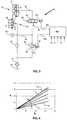
- Figure 1 is a schematic representation of a driveline incorporating a continuously variable transmission;
- Figure 2 is a side elevation of the continuously variable transmission as seen in cross section;
- Figure 3 is a schematic representation of an electro-hydraulic control system for a continuously variable transmission according to the known art;
- Figure 4 illustrates the relation between the transmission ratio and the ratio between the first and second pressure for the transmission according to the known art;
- Figure 5 is a schematic representation of a control system in a first embodiment of the invention;
- Figure 6 is a schematic representation of a control system in a second embodiment of the invention;
- Figure 7 is a schematic representation of a control system in a third embodiment of the invention;
- Figure 8 is an optimised version of the third embodiment of the invention according to figure 7.
-
- Figure 1 schematically shows a driveline, as e.g. used for vehicular propulsion or for driving an electrical generator, provided with an engine and a load, as well as a continuously
variable transmission 1 provided there between. The transmission comprises a firstrotatable disc pair 10, at least onedisc 11 of thediscs first medium chamber 15 defined by a piston-cylinder assembly first disc pair 10, a secondrotatable disc pair 20, at least onedisc 21 of thediscs second medium chamber 25 defined by a piston-cylinder assembly second disc pair 20, and adrive belt 2 running around said first andsecond disc pairs transmission 1. In the transmission configuration shown in figure 1, the running radius R10 of thedrive belt 2 around thefirst disc pair 10 is smaller than the running radius R20 around thesecond disc pair 20. In this configuration, when the engine drives the load, a torque TE generated by the engine on thefirst disc pair 10 is increased by thetransmission 1 when it is transferred to the load, whereas a rotational speed of engine NE is decreased. Such transmission conditions where the running radius R10 is smaller than the running radius R20 are so-called decelerating conditions, whereas transmission conditions where the running radius R10 is larger than the running radius R20 are so-called accelerating conditions. By controlling the first pressure P1 and the second pressure P2, respective clamping forces, which are exerted by therespective disc pairs drive belt 2 running between thediscs transmission 1 is provided with a -pressure- control system that will be discussed later on. The clamping forces allow torque to be transferred between thedisc pairs belt 2 through friction and, moreover, their mutual force ratio determines the instantaneous transmission ratio i of thetransmission 1, which may be varied between a most decelerating transmission ratio iD and a most accelerating transmission ratio iA. - Figure 2 shows a side elevation of the
transmission 1 according to the cross section A-A indicated in figure 1. Thedrive belt 2 is shown to run at the smaller running radius R10 ondisc 12 of thefirst disc pair 10 and at the larger running radius R20 ondisc 21 of thesecond disc pair 20. Thetransmission 1 may be equipped with several types of drive belt such as a rubber belt or a chain. However, thedrive belt 2 shown in figure 2 is a so-called push belttype drive belt 2, which is composed of a large number of plate-like transverse elements or blocks 3 that are provided freely movable along the circumference of an endless tensile means or carrier 4. This type ofdrive belt 2 is well known and is characterised by the feature that the engine torque TE may be transferred between the disc pairs 10 and 20 by the blocks 3 pushing each other forward in a direction of rotation DR. - In figure 3 a
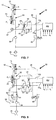
pressure control system 30 for the knowntransmission 1 is schematically illustrated showing only the relevant parts thereof. Thecontrol system 30 according to the contemporary state of the art comprises an electronic part and a hydraulic part, whereby electromagneticallyoperable valves control system 30 compriseshydraulic circuits medium chamber 15 and a secondhydraulic circuit 34 includes the secondmedium chamber 25. The control system is further provided with: - a
pressure valve 32 situated between the secondhydraulic circuit 34 and amedium sink 35 for controlling the second pressure P2 that prevails in the secondhydraulic circuit 34 by allowing a smaller or larger flow of medium from the secondhydraulic circuit 34 to themedium sink 35, - a
flow valve 31 situated between the secondhydraulic circuit 34 and the firsthydraulic circuit 33 for controlling the first pressure P1 that prevails in the firsthydraulic circuit 33 by allowing a smaller of larger flow of medium either from the second hydraulic 34 circuit to the firsthydraulic circuit 33, or from the firsthydraulic circuit 33 to amedium sink 35, and - a
pump 36 for generating a flow of medium, i.e. a so-called pump flow, from themedium sink 35 to thesecond circuit 34. - The structure and functioning of hydraulic valves such as the
pressure valve 32 and flowvalve 31 are generally known in the art, however, it is summarised here that the known valve types usually comprise a valve body axially movably provided in a valve housing, whereby the relative (axial) position of the valve body within said housing determines a cross sectional surface area available for a medium flow through the valve between two of possibly several hydraulic channels connected to the valve. Such position is denoted as the valve setting. The said relative position of the valve body may be varied by varying at least one of several forces that usually act on at least two axially oriented end faces the valve body located on opposite ends thereof determining its position and/or movement within the valve housing, which at least one force is denoted here as the pilot force PF. The pilot force PF may, for instance, be realised mechanically by a so-called solenoid in dependency on an electric pilot signal PS. It is also known in the art to adopt a solenoid operated valve for converting the said pilot signal PS into a hydraulic pilot pressure that acts on an axially oriented end face of the valve body thus realising the pilot force PF that is dependent on the level of the pilot pressure and the specific surface area of the end face on which it acts. - In figure 3 it is indicated that the electronic part of the
control system 30 comprises a control unit CU, which unit is used for determining -an electronic representation of- desired levels of the first pressure P1 and of the second pressure P2 based on any number and origin of input signals usually including at least the rotational speed of the engine NE, the engine torque TE, the transmission ratio i and the second pressure P2, the latter being measured by means of apressure sensor 37 associated with the secondhydraulic circuit 34. The control unit CU also converts these desired pressure levels P1 and P2 into respective pilot signals PS1 and PS2 so as to effect valve settings of theflow valve 31 and thepressure valve 32 appropriate for realising these desired pressures P1 and P2. The valve setting of theflow valve 31 is determined by a balance between a force effected by aspring 38 and a first pilot force PF1 realised in dependency on a first pilot signal PS1, whereas the valve setting of thepressure valve 32 is determined by a balance between on the one hand a force effected by the second pressure P2 by means of apressure feedback duct 39 and on the other hand a force effected by aspring 40 and a second pilot force PF2 realised in dependency on a second pilot signal PS2. The pressure level of each of the said first pressure P1 and the said second pressure P2 in combination with an active surface area of the respectivemedium chamber 15; 25 determines the clamping force that is exerted by therespective disc pair drive belt 2. These clamping forces allow a transfer of torque between thedrive belt 2 and the disc pairs 10; 20 through friction and, moreover, influence the transmission ratio i. Because the known construction only allows the first pressure P1 to become equal to or smaller than the second pressure P2, an active surface area of the firstmedium chamber 15 is made larger than that of the secondmedium chamber 25 to allow the clamping force exerted by thefirst disc pair 10 to become larger than that of thesecond disc pair 20. This is realised by the larger diameter D1 of themedium chamber 15 of thefirst disc pair 10 compared to the diameter D2 of themedium chamber 25 of thesecond disc pair 20 as indicated in figure 3. Finally, withreference numeral 41 it is indicated in figure 3 that the knowncontrol system 30 usually is provided with a medium cooler and filter. - In figure 4 the effect of the level of the first pressure P1 and the second pressure P2 on the transmission ratio i are illustrated as a graph. In this example the second pressure P2 may be controlled up to a level of 65 bar in dependency on the amount of torque that is to be transferred between the
drive belt 2 and thesecond disc pair 20. The characteristics of thecontrol system 30 including the relative size of the said active surface areas are chosen such that for any given level of the second pressure P2, the first pressure P1 may be varied between a level P1-MIN realising the most decelerating transmission ratio iD and a level P1-MAX realising the most accelerating transmission ratio iA of thetransmission 1. - The known
transmission 1 and more in particular the knownflow valve 31 has the disadvantage that it is not particularly suited for accurate adjustment of small medium flows that regularly occur during operation of thetransmission 1. Such accurate adjustments are, however, highly desirable for achieving optimum transmission efficiency and for optimising operational reliability. Another disadvantage of the known transmission is that there is no immediate relation between the first pilot signal PS1 and the first pressure P1 that is actually set. For example, when the first pilot signal PS1 corresponds to a valve setting where theflow valve 31 is closed, i.e. allowing no medium flow at all, the first pressure P1 may have, or obtain through medium leakage, any value between the level of the second pressure P2 and a pressure prevailing in themedium sink 35, which usually is equal to the atmospheric pressure of about 1 bar. Particular at standstill, or shortly thereafter during acceleration of the load, the clamping force at thefirst disc pair 10 may unwittingly become too low for adequate torque transfer between thedrive belt 2 and thediscs first disc pair 10, which disadvantageously results in slip of thedrive belt 2 between the saiddiscs - , The invention, as is illustrated in figures 5 to 8, provides for a continuously
variable transmission 1 having animproved control system 30 that is characterised by the features that the firsthydraulic circuit 33, the secondhydraulic circuit 34 and thepump 36 are hydraulically arranged in series and that there is provided afirst valve 42; 43; 44 connecting the saidhydraulic circuits first valve 42; 43; 44 is capable of realising a variable pressure difference between the first pressure P1 and the second pressure P2 prevailing in the said first andsecond circuits hydraulic circuits transmission 1 according to the invention has the advantage that a relatively large flow of medium passes through thefirst valve 42; 43; 44, which has an advantageous effect on the accuracy with which the control system may operate. In steady state transmission conditions the entire flow supplied to the secondhydraulic circuit 34 advantageously flows through thefirst valve 42; 43; 44. - In a first embodiment of the invention, which is schematically shown in figure 5, the
first valve 42; 43; 44 comprises a variablerestrictor type valve 42. Such a variablerestrictor type valve 42 is capable of restricting, alternatively denoted impeding, the medium flow between the saidcircuits circuits control system 30 is further provided with asecond valve 45 situated between the firsthydraulic circuit 33 and amedium sink 35 for influencing the first pressure P1 by allowing a smaller or larger flow of medium from the firsthydraulic circuit 33 to themedium sink 35. Preferably, thesecond valve 45 conforms to the known pressurecontrol type valve 32. The variable flowrestrictor type valve 42 has the particular advantage that it is of relatively simple construction and accordingly may be implemented relatively cheaply. - In a second embodiment of the invention that is schematically shown in figure 6 the
first valve 42; 43; 44 comprises a variable pressuredifferential type valve 43. The valve setting of this type of valve is not only determined by the level or magnitude of first pilot signal PS1, but also by the level of the first pressure P1 and the level of the second pressure P2. Preferably, the latter influences are realised by providing ducts, e.g. as indicated in figure 6 as thedotted lines control type valve 43. Thereby, the influence of each of the pressures P1 and P2 is preferably such that changes in that respective pressure P1; P2 are counteracted. This arrangement has the advantage that, when the second pressure P2 changes, e.g. increases in accordance with an increase in engine torque TE that is to be transferred by thetransmission 1, the first pressure P1 has the tendency to change accordingly, whereby the pressure ratio between said pressures P1 and P2 advantageously changes only slightly if at all, resulting in a stable transmission ratio i. Moreover, by selecting suitable surface areas of the said end faces of the said valve body on which the pressures P1 and P2 act, it may be realised that for a given magnitude of the first pilot signal PS1 and the accompanying transmission ratio i, the said pressure ratio and thus also the transmission ratio i remains virtually constant. Preferably this transmission ratio i corresponds to the most decelerating transmission condition iD, because in this condition thetransmission 1 is usually the most highly loaded and, moreover, this arrangement advantageously ensures that in all other transmission conditions an increase in the second pressure P2 results in an increase in the first pressure P1 and vice versa. The latter behaviour conforms to a generally preferred transmission behaviour, whereby the transmission ratio i becomes more decelerating when the engine torque TE increases and vice versa. The differential pressure type valve and its particular advantages, albeit in combination with a conventional control system, are extensively described in the unpublished European patent application 00204670.4. - In a third embodiment of the invention that is schematically shown in figure 7 the
first valve 42; 43; 44 comprises a variable flowcontrol type valve 44. The valve setting of this type ofvalve 44 is not only determined in dependency on the first pilot signal PS1, but also in dependency on the amount of said flow of medium from thesecond circuit 34 to thefirst circuit 33. In the figure 7 it is shown that this may be realised by allowing a flow dependent pressure drop over a restrictor 48 positioned in the firsthydraulic circuit 33 immediately after a variable pressure differential type valve 55, whereby the valve setting of variable pressure differential type valve 55 is influenced by the said pressure drop. Preferably, the latter is realised by providing ducts, e.g. as is also indicated in figure 7 by the dottedlines control type valve 44 are counteracted. According to the invention this arrangement has the particular advantage that when the setting of thesecond valve 45 is changed, for example such that the first pressure P1 increases, the variable flowcontrol type valve 44 adjust itself so as to maintain a constant flow between thehydraulic circuits transmission 1 without mutual notional slip of thebelt 2 and the disc pairs 10 and 20. - For optimising the above mentioned advantageous control behaviour, the invention suggests two further improvements to the third embodiment of the invention that are illustrated in figure 8. According to a first improvement the pump flow should be as constant as possible to realise an optimum stability of the control system. Hereby it is prevented that -a change in- the pump flow would additionally and disadvantageously influence the valve setting of the variable flow
control type valve 44, that is, independent from changes in the setting of thesecond valve 45. However, this is not normally the case since the pump flow will usually depend on the pressure gradient over thepump 36 and accordingly on the first pressure P1 as well as on other parameters. Moreover, it is remarked that the same engine that drives thetransmission 1 and the load often also drives thepump 36. Accordingly, the medium flow generated by thepump 36 depends on the engine speed NE and thus will vary during operation of thetransmission 1. The invention provides a solution to this problem in the addition of athird valve 49 that realises a fixed amount of medium flow from thepump 36 into the secondhydraulic circuit 34 by branching-off into a furtherhydraulic circuit 50 of an mount of flow that is generated by thepump 36 in excess a the said fixed amount. According to the invention, suchthird valve 49 may comprise a restrictor 51, which is constituted by a narrowing in a hydraulic channel or duct carrying the pump flow into thesecond circuit 34 and which realises a pump flow dependent pressure drop, and apressure control valve 52 situated between thesecond circuit 34 and the furtherhydraulic circuit 50, which is operable under the influence of the said pressure drop in such a manner that medium flow is increasingly branched-off when the said pressure drop increases and vice versa. According to the invention, for a reliable transmission operation, thepump 36 is dimensioned such that it can provide an amount of flow equal to or slightly larger than the said constant amount of flow under all circumstances during normal operation. When thepump 36 is directly driven by the same engine that drives the load, this means that thepump 36 is preferably dimensioned such that it is capable of delivering the said constant amount of flow at the lowest engine speed NE that occurs during normal operation, e.g. idle engine speed in automotive applications. The branched-off flow need not be fed directly into thereservoir 35, but may be advantageously used for other typical functions of thecontrol system 30 such as lubrication or clutch control. - It is noted that, since the medium flow through the
control system 30 and the pressures P1; P2 prevailing therein mutually influence each other, the responsiveness and control behaviour of in fact every embodiment of thecontrol system 30 according to the invention may be improved considerably by incorporating the above-mentionedthird valve 49. However, the effects thereof are considered the most desirable in combination with the third embodiment of the invention. - According to the invention the control behaviour of the third embodiment of the invention may be further optimised by a second improvement that entails constructing the variable flow
control type valve 44 as twosub-valves first sub-valve 53 is a variable restrictor type valve similar to thevalve 42 used in the first embodiment of the invention and the second sub-valve 54 is a pressure differential type valve similar to thevalve 43 used in the second embodiment of the invention. Bothvalves ducts restrictor type valve 53. The saidducts second sub-valve 54. The second sub-valve 54 actually determines the flow between the first and secondhydraulic circuits first sub-valve 53, disturbs the pressures and flows prevailing in the control system only slightly, whereas the real work of controlling the first pressure P1 by determining the flow between thefirst circuit 33 and thesecond circuit 34 is performed by another valve, i.e. the pressure differential typesecond sub-valve 54. Such separation of functions can significantly improve the stability of the control behaviour of thesystem 30. - In yet a further development of the invention, applicable to any embodiment of the invention, the second pilot signal PS2 of the
second valve 45, which for this purpose preferably is of the known pressure valve type, is determined by the CU based on the difference between an actual, i.e. measured second pressure P2, and a desired pressure P2 determined by the control unit CU. Rather surprisingly, thepressure sensor 37 is, according to the invention, thus associated with thesecond circuit 34 although thesecond valve 45 is situated between thefirst circuit 33 and themedium sink 35. Accordingly, thesecond valve 45 influences the second pressure P2 only indirectly because of the presence of thefirst valve 42; 43; 44 situated between thesecond valve 45 and the secondhydraulic circuit 34. This unconventional arrangement has the unexpected advantage that, even when using only asingle pressure sensor 37, at standstill both said pressures P1 and P2 are relatively accurately known, because the second pressure P2 may be measured by means of thepressure sensor 37, whereas the first pressure P1 may be estimated using a predetermined characteristic of the pressure valve typesecond valve 45, which characteristic provides an approximation of the pressure set by thesecond valve 45, being the first pressure P1, in dependency on the level or magnitude of the second pilot signal PS2 and may be determined with sufficient accuracy. Thereby, the said slip of thedrive belt 2 during standstill or initial acceleration may be prevented adequately and reliably. - Whilst the above has been described with reference to essentially preferred embodiments and best possible modes it will be understood that these embodiments are by no means to be construed as limiting examples of the
transmissions 1 andcontrol systems 30 concerned, because various modifications, features and combination of features falling within the scope of the appended claims are now within reach of the skilled person.
Claims (9)
- Continuously variable transmission (1) comprising a first rotatable disc pair (10), at least one (11) of the discs (11, 12) thereof being axially displaceable under the influence of a first pressure (P1) in a first medium chamber (15) of a piston-cylinder assembly (13, 14) associated with the said first disc pair (10), a second rotatable disc pair (20), at least one (21) of the discs (21, 22) thereof being axially displaceable under the influence of a second pressure (P2) in a second medium chamber (25) of a piston-cylinder assembly (23, 24) associated with the said second disc pair (20) and a pressure control system (30) comprising a first hydraulic circuit (33) including the said first medium chamber (15), a second hydraulic circuit (34) including the said second medium chamber (25), a source (36) for supplying a medium flow into the second hydraulic circuit (34) and a first hydraulic valve (42; 43; 44) situated between the said hydraulic circuits (33 and 34), whereby the second hydraulic circuit (34) and the first hydraulic circuit (33) are arranged in series with respect to the said medium flow, whereby the first valve (42; 43; 44) is capable of affecting a flow of medium from the second hydraulic circuit (34) to the first hydraulic circuit (33) such that a pressure difference may be effected between the second pressure (P2) and the first pressure (P1) and whereby the control system (30) is further provided with a second valve (45) capable of affecting a flow of medium from the first hydraulic circuit (33) to a medium sink (35) such that a first pressure (P1) is set, characterised in that, the second valve (45) is controlled in dependency on a desired second pressure and an actually measured second pressure (P2) such that a difference there between is minimised.
- Continuously variable transmission according to claim 1, characterised in that the second valve (45) is a pressure control type valve having a predetermined control characteristic between a pressure valve control signal (PS2) and the pressure (P1) set by the valve.
- Continuously variable transmission according to claim 1 or 2, characterised in that the first valve (42; 43; 44) comprises a variable restrictor type valve (42), which valve (42) is capable of controlling the cross sectional surface area of an opening available for the said flow of medium from the second hydraulic circuit (34) to the first hydraulic circuit (33) in dependency on a first pilot signal (PS1)
- Continuously variable transmission according to claim 1 or 2, characterised in that the first valve (42; 43; 44) is a variable pressure differential type valve (43) by means of which the said pressure difference may be influenced in dependency on all three of a first pilot signal (PS1), the first pressure (P1) and the second pressure (P2).
- Continuously variable transmission according to claim 1 or 2, characterised in that the first valve (42; 43; 44) comprises a variable flow control type valve (44) by means of which the said pressure difference may be influenced in dependency on a first pilot signal (PS1) and on the amount of said flow of medium through the valve (44).
- Continuously variable transmission according to claim 5, characterised in that the variable flow control type valve (44) is composed of a restrictor (48) for realising a flow dependent pressure drop in the said flow of medium from the second hydraulic circuit (34) to the first hydraulic circuit (33) and a pressure differential type valve (55) operable under the influence of the said pressure drop and a first pilot signal (PS1).
- Continuously variable transmission according to claim 5, characterised in that the variable flow control type valve (44) is composed of a variable restrictor type valve (53) for realising a flow dependent pressure drop in the said flow of medium from the second hydraulic circuit (34) to the first hydraulic circuit (33) in dependency on a first pilot signal (PS1) and a pressure differential type valve (54) operable under the influence of the said pressure drop.
- Continuously variable transmission according to any one of the preceding claims, characterised in that the control system (30) is further provided with a third valve (49; 51, 52) for making the said medium flow into the second hydraulic circuit (34) constant by branching-off into a further hydraulic circuit (50) of any excess amount of flow generated by the said source (36).
- Use of the continuously variable transmission according to any one of the preceding claims for performing a traction process in a vehicle or to a mechanical load process in an aeroplane or ship, preferably for performing a mechanical load process wherein an engine drives the said first disc pair 10 at a variable rotational speed NE and a load is driven by the said second disc pair 20 at an essentially constant rotational speed.
Priority Applications (5)
| Application Number | Priority Date | Filing Date | Title |
|---|---|---|---|
| DE60106722T DE60106722T2 (en) | 2001-03-23 | 2001-03-23 | Stepless transmission with a precise pressure control device |
| AT01201087T ATE280917T1 (en) | 2001-03-23 | 2001-03-23 | CONTINUOUSLY VARIABLE TRANSMISSION WITH AN ACCURATE PRESSURE CONTROL DEVICE |
| EP20010201087 EP1243817B1 (en) | 2001-03-23 | 2001-03-23 | Continuously variable transmission having an accurate pressure control system |
| PCT/EP2002/003174 WO2002077493A1 (en) | 2001-03-23 | 2002-03-21 | Continuously variable transmission having an accurate pressure control system |
| JP2002575509A JP4205429B2 (en) | 2001-03-23 | 2002-03-21 | Continuously variable transmission with precision pressure control system |
Applications Claiming Priority (1)
| Application Number | Priority Date | Filing Date | Title |
|---|---|---|---|
| EP20010201087 EP1243817B1 (en) | 2001-03-23 | 2001-03-23 | Continuously variable transmission having an accurate pressure control system |
Publications (2)
| Publication Number | Publication Date |
|---|---|
| EP1243817A1 EP1243817A1 (en) | 2002-09-25 |
| EP1243817B1 true EP1243817B1 (en) | 2004-10-27 |
Family
ID=8180052
Family Applications (1)
| Application Number | Title | Priority Date | Filing Date |
|---|---|---|---|
| EP20010201087 Expired - Lifetime EP1243817B1 (en) | 2001-03-23 | 2001-03-23 | Continuously variable transmission having an accurate pressure control system |
Country Status (5)
| Country | Link |
|---|---|
| EP (1) | EP1243817B1 (en) |
| JP (1) | JP4205429B2 (en) |
| AT (1) | ATE280917T1 (en) |
| DE (1) | DE60106722T2 (en) |
| WO (1) | WO2002077493A1 (en) |
Families Citing this family (2)
| Publication number | Priority date | Publication date | Assignee | Title |
|---|---|---|---|---|
| ITFI20130156A1 (en) | 2013-07-01 | 2015-01-02 | Scuola Superiore Sant Anna | TORSIONAL SPRING |
| JP6439756B2 (en) * | 2016-07-07 | 2018-12-19 | トヨタ自動車株式会社 | Control device for vehicle transmission |
Family Cites Families (6)
| Publication number | Priority date | Publication date | Assignee | Title |
|---|---|---|---|---|
| IT1201307B (en) | 1985-06-03 | 1989-01-27 | Penna Flli | Variable attitude awning for vehicle |
| DE3938539A1 (en) * | 1989-11-21 | 1991-06-06 | Ford Werke Ag | CONTROL SYSTEM FOR A CONTINUOUSLY ADJUSTABLE CONE DISC BELT GEARBOX |
| NL9000860A (en) | 1990-04-12 | 1991-11-01 | Doornes Transmissie Bv | ELECTRONICALLY CONTROLLED CONTINUOUSLY VARIABLE TRANSMISSION. |
| DE19519163A1 (en) * | 1995-05-24 | 1996-11-28 | Bosch Gmbh Robert | Hydraulic emergency control for changing the hydraulic oil pressures in the hydraulic conical pulley axial adjustment of a continuously variable belt transmission to vary the clamping force ratios |
| NL1002245C2 (en) | 1996-02-05 | 1997-08-07 | Doornes Transmissie Bv | Continuously variable transmission. |
| US6126138A (en) | 1998-12-30 | 2000-10-03 | Hamilton Sundstrand Corporation | Pressure reducing valve and continuously variable transmission with control arrangement using same |
-
2001
- 2001-03-23 AT AT01201087T patent/ATE280917T1/en not_active IP Right Cessation
- 2001-03-23 DE DE60106722T patent/DE60106722T2/en not_active Expired - Lifetime
- 2001-03-23 EP EP20010201087 patent/EP1243817B1/en not_active Expired - Lifetime
-
2002
- 2002-03-21 WO PCT/EP2002/003174 patent/WO2002077493A1/en active Application Filing
- 2002-03-21 JP JP2002575509A patent/JP4205429B2/en not_active Expired - Fee Related
Also Published As
| Publication number | Publication date |
|---|---|
| ATE280917T1 (en) | 2004-11-15 |
| WO2002077493A1 (en) | 2002-10-03 |
| DE60106722T2 (en) | 2005-11-10 |
| DE60106722D1 (en) | 2004-12-02 |
| JP4205429B2 (en) | 2009-01-07 |
| EP1243817A1 (en) | 2002-09-25 |
| JP2004522094A (en) | 2004-07-22 |
Similar Documents
| Publication | Publication Date | Title |
|---|---|---|
| US4669336A (en) | Apparatus for controlling line pressure used in V-belt type continuously variable transmission for automobile | |
| EP0304085B1 (en) | Hydraulic control device for belt-and-pulley type continuously variable transmission for a vehicle | |
| US4534243A (en) | Hydraulic control system for a V-belt transmission | |
| EP0228884B1 (en) | System for controlling transmission ratio of a continuously variable transmission for a motor vehicle | |
| US6623386B1 (en) | Oil-hydraulic circuit of belt-type continuous variable speed-change transmission | |
| US20010023217A1 (en) | Hydraulic control system for a continuously variable transmission | |
| EP0117696A1 (en) | Hydraulic apparatus for a continuously variable transmission | |
| GB2260379A (en) | Control system for continuously-variable transmission | |
| JPH0586511B2 (en) | ||
| EP0982512B1 (en) | Clutch hydraulic controller | |
| EP0289025B1 (en) | Belt-and-pulley type continuously variable transmission | |
| US20110118066A1 (en) | Sheave positioning device | |
| KR100564195B1 (en) | Shift hydraulic pressure control apparatus for belt type continuously variable transmission | |
| US6350215B1 (en) | Hydraulic control system for pressure control of a CVT variator with limp home mode | |
| US5156572A (en) | Speed shift control system of a continuous transmission | |
| GB2298907A (en) | An electrohydraulic control system for a continuously-variable transmission. | |
| JP2994003B2 (en) | Hydraulic control device for hydraulically operated transmission | |
| US6503169B2 (en) | Apparatus for controlling a power transmission device | |
| EP1243817B1 (en) | Continuously variable transmission having an accurate pressure control system | |
| EP1217266B1 (en) | Control system and continuously variable transmission provided therewith | |
| JP4164787B2 (en) | Gear ratio control device for continuously variable transmission | |
| KR100504419B1 (en) | Emergency hydraulic control for adjusting a constant clamping force ratio with regard to a continuously variable tranmission | |
| KR100357553B1 (en) | Hydraulic control system for continuously variable transmission | |
| JP2004522094A5 (en) | ||
| JP2792370B2 (en) | Hydraulic control device for continuously variable transmission |
Legal Events
| Date | Code | Title | Description |
|---|---|---|---|
| PUAI | Public reference made under article 153(3) epc to a published international application that has entered the european phase |
Free format text: ORIGINAL CODE: 0009012 |
|
| AK | Designated contracting states |
Kind code of ref document: A1 Designated state(s): AT BE CH CY DE DK ES FI FR GB GR IE IT LI LU MC NL PT SE TR |
|
| AX | Request for extension of the european patent |
Free format text: AL;LT;LV;MK;RO;SI |
|
| 17P | Request for examination filed |
Effective date: 20030325 |
|
| AKX | Designation fees paid |
Designated state(s): AT BE CH CY DE DK ES FI FR GB GR IE IT LI LU MC NL PT SE TR |
|
| 17Q | First examination report despatched |
Effective date: 20030526 |
|
| GRAP | Despatch of communication of intention to grant a patent |
Free format text: ORIGINAL CODE: EPIDOSNIGR1 |
|
| GRAS | Grant fee paid |
Free format text: ORIGINAL CODE: EPIDOSNIGR3 |
|
| GRAA | (expected) grant |
Free format text: ORIGINAL CODE: 0009210 |
|
| AK | Designated contracting states |
Kind code of ref document: B1 Designated state(s): AT BE CH CY DE DK ES FI FR GB GR IE IT LI LU MC NL PT SE TR |
|
| PG25 | Lapsed in a contracting state [announced via postgrant information from national office to epo] |
Ref country code: IT Free format text: LAPSE BECAUSE OF FAILURE TO SUBMIT A TRANSLATION OF THE DESCRIPTION OR TO PAY THE FEE WITHIN THE PRESCRIBED TIME-LIMIT;WARNING: LAPSES OF ITALIAN PATENTS WITH EFFECTIVE DATE BEFORE 2007 MAY HAVE OCCURRED AT ANY TIME BEFORE 2007. THE CORRECT EFFECTIVE DATE MAY BE DIFFERENT FROM THE ONE RECORDED. Effective date: 20041027 Ref country code: FI Free format text: LAPSE BECAUSE OF FAILURE TO SUBMIT A TRANSLATION OF THE DESCRIPTION OR TO PAY THE FEE WITHIN THE PRESCRIBED TIME-LIMIT Effective date: 20041027 Ref country code: CH Free format text: LAPSE BECAUSE OF FAILURE TO SUBMIT A TRANSLATION OF THE DESCRIPTION OR TO PAY THE FEE WITHIN THE PRESCRIBED TIME-LIMIT Effective date: 20041027 Ref country code: TR Free format text: LAPSE BECAUSE OF FAILURE TO SUBMIT A TRANSLATION OF THE DESCRIPTION OR TO PAY THE FEE WITHIN THE PRESCRIBED TIME-LIMIT Effective date: 20041027 Ref country code: LI Free format text: LAPSE BECAUSE OF FAILURE TO SUBMIT A TRANSLATION OF THE DESCRIPTION OR TO PAY THE FEE WITHIN THE PRESCRIBED TIME-LIMIT Effective date: 20041027 Ref country code: AT Free format text: LAPSE BECAUSE OF FAILURE TO SUBMIT A TRANSLATION OF THE DESCRIPTION OR TO PAY THE FEE WITHIN THE PRESCRIBED TIME-LIMIT Effective date: 20041027 |
|
| REG | Reference to a national code |
Ref country code: GB Ref legal event code: FG4D |
|
| REG | Reference to a national code |
Ref country code: CH Ref legal event code: EP |
|
| REG | Reference to a national code |
Ref country code: IE Ref legal event code: FG4D |
|
| REF | Corresponds to: |
Ref document number: 60106722 Country of ref document: DE Date of ref document: 20041202 Kind code of ref document: P |
|
| PG25 | Lapsed in a contracting state [announced via postgrant information from national office to epo] |
Ref country code: SE Free format text: LAPSE BECAUSE OF FAILURE TO SUBMIT A TRANSLATION OF THE DESCRIPTION OR TO PAY THE FEE WITHIN THE PRESCRIBED TIME-LIMIT Effective date: 20050127 Ref country code: GR Free format text: LAPSE BECAUSE OF FAILURE TO SUBMIT A TRANSLATION OF THE DESCRIPTION OR TO PAY THE FEE WITHIN THE PRESCRIBED TIME-LIMIT Effective date: 20050127 Ref country code: DK Free format text: LAPSE BECAUSE OF FAILURE TO SUBMIT A TRANSLATION OF THE DESCRIPTION OR TO PAY THE FEE WITHIN THE PRESCRIBED TIME-LIMIT Effective date: 20050127 |
|
| PG25 | Lapsed in a contracting state [announced via postgrant information from national office to epo] |
Ref country code: ES Free format text: LAPSE BECAUSE OF FAILURE TO SUBMIT A TRANSLATION OF THE DESCRIPTION OR TO PAY THE FEE WITHIN THE PRESCRIBED TIME-LIMIT Effective date: 20050207 |
|
| PG25 | Lapsed in a contracting state [announced via postgrant information from national office to epo] |
Ref country code: CY Free format text: LAPSE BECAUSE OF FAILURE TO SUBMIT A TRANSLATION OF THE DESCRIPTION OR TO PAY THE FEE WITHIN THE PRESCRIBED TIME-LIMIT Effective date: 20050323 Ref country code: IE Free format text: LAPSE BECAUSE OF NON-PAYMENT OF DUE FEES Effective date: 20050323 Ref country code: LU Free format text: LAPSE BECAUSE OF NON-PAYMENT OF DUE FEES Effective date: 20050323 |
|
| PG25 | Lapsed in a contracting state [announced via postgrant information from national office to epo] |
Ref country code: MC Free format text: LAPSE BECAUSE OF NON-PAYMENT OF DUE FEES Effective date: 20050331 |
|
| REG | Reference to a national code |
Ref country code: CH Ref legal event code: PL |
|
| PLBE | No opposition filed within time limit |
Free format text: ORIGINAL CODE: 0009261 |
|
| STAA | Information on the status of an ep patent application or granted ep patent |
Free format text: STATUS: NO OPPOSITION FILED WITHIN TIME LIMIT |
|
| ET | Fr: translation filed | ||
| 26N | No opposition filed |
Effective date: 20050728 |
|
| REG | Reference to a national code |
Ref country code: IE Ref legal event code: MM4A |
|
| PG25 | Lapsed in a contracting state [announced via postgrant information from national office to epo] |
Ref country code: PT Free format text: LAPSE BECAUSE OF NON-PAYMENT OF DUE FEES Effective date: 20050327 |
|
| PGFP | Annual fee paid to national office [announced via postgrant information from national office to epo] |
Ref country code: BE Payment date: 20100323 Year of fee payment: 10 |
|
| BERE | Be: lapsed |
Owner name: *VAN DOORNE'S TRANSMISSIE B.V. Effective date: 20110331 |
|
| PG25 | Lapsed in a contracting state [announced via postgrant information from national office to epo] |
Ref country code: BE Free format text: LAPSE BECAUSE OF NON-PAYMENT OF DUE FEES Effective date: 20110331 |
|
| PGFP | Annual fee paid to national office [announced via postgrant information from national office to epo] |
Ref country code: FR Payment date: 20130329 Year of fee payment: 13 Ref country code: GB Payment date: 20130318 Year of fee payment: 13 |
|
| PGFP | Annual fee paid to national office [announced via postgrant information from national office to epo] |
Ref country code: NL Payment date: 20130318 Year of fee payment: 13 |
|
| PGFP | Annual fee paid to national office [announced via postgrant information from national office to epo] |
Ref country code: DE Payment date: 20130523 Year of fee payment: 13 |
|
| REG | Reference to a national code |
Ref country code: DE Ref legal event code: R119 Ref document number: 60106722 Country of ref document: DE |
|
| REG | Reference to a national code |
Ref country code: NL Ref legal event code: V1 Effective date: 20141001 |
|
| GBPC | Gb: european patent ceased through non-payment of renewal fee |
Effective date: 20140323 |
|
| REG | Reference to a national code |
Ref country code: FR Ref legal event code: ST Effective date: 20141128 |
|
| REG | Reference to a national code |
Ref country code: DE Ref legal event code: R119 Ref document number: 60106722 Country of ref document: DE Effective date: 20141001 |
|
| PG25 | Lapsed in a contracting state [announced via postgrant information from national office to epo] |
Ref country code: GB Free format text: LAPSE BECAUSE OF NON-PAYMENT OF DUE FEES Effective date: 20140323 Ref country code: DE Free format text: LAPSE BECAUSE OF NON-PAYMENT OF DUE FEES Effective date: 20141001 Ref country code: FR Free format text: LAPSE BECAUSE OF NON-PAYMENT OF DUE FEES Effective date: 20140331 |
|
| PG25 | Lapsed in a contracting state [announced via postgrant information from national office to epo] |
Ref country code: NL Free format text: LAPSE BECAUSE OF NON-PAYMENT OF DUE FEES Effective date: 20141001 |