EP1243782A2 - Double jet engine inlet - Google Patents
Double jet engine inlet Download PDFInfo
- Publication number
- EP1243782A2 EP1243782A2 EP02075713A EP02075713A EP1243782A2 EP 1243782 A2 EP1243782 A2 EP 1243782A2 EP 02075713 A EP02075713 A EP 02075713A EP 02075713 A EP02075713 A EP 02075713A EP 1243782 A2 EP1243782 A2 EP 1243782A2
- Authority
- EP
- European Patent Office
- Prior art keywords
- air inlet
- engine
- aircraft
- passage
- boundary layer
- Prior art date
- Legal status (The legal status is an assumption and is not a legal conclusion. Google has not performed a legal analysis and makes no representation as to the accuracy of the status listed.)
- Granted
Links
Images

Classifications
-
- F—MECHANICAL ENGINEERING; LIGHTING; HEATING; WEAPONS; BLASTING
- F02—COMBUSTION ENGINES; HOT-GAS OR COMBUSTION-PRODUCT ENGINE PLANTS
- F02C—GAS-TURBINE PLANTS; AIR INTAKES FOR JET-PROPULSION PLANTS; CONTROLLING FUEL SUPPLY IN AIR-BREATHING JET-PROPULSION PLANTS
- F02C7/00—Features, components parts, details or accessories, not provided for in, or of interest apart form groups F02C1/00 - F02C6/00; Air intakes for jet-propulsion plants
- F02C7/04—Air intakes for gas-turbine plants or jet-propulsion plants
-
- B—PERFORMING OPERATIONS; TRANSPORTING
- B64—AIRCRAFT; AVIATION; COSMONAUTICS
- B64D—EQUIPMENT FOR FITTING IN OR TO AIRCRAFT; FLIGHT SUITS; PARACHUTES; ARRANGEMENT OR MOUNTING OF POWER PLANTS OR PROPULSION TRANSMISSIONS IN AIRCRAFT
- B64D33/00—Arrangement in aircraft of power plant parts or auxiliaries not otherwise provided for
- B64D33/02—Arrangement in aircraft of power plant parts or auxiliaries not otherwise provided for of combustion air intakes
-
- F—MECHANICAL ENGINEERING; LIGHTING; HEATING; WEAPONS; BLASTING
- F02—COMBUSTION ENGINES; HOT-GAS OR COMBUSTION-PRODUCT ENGINE PLANTS
- F02K—JET-PROPULSION PLANTS
- F02K3/00—Plants including a gas turbine driving a compressor or a ducted fan
- F02K3/02—Plants including a gas turbine driving a compressor or a ducted fan in which part of the working fluid by-passes the turbine and combustion chamber
- F02K3/04—Plants including a gas turbine driving a compressor or a ducted fan in which part of the working fluid by-passes the turbine and combustion chamber the plant including ducted fans, i.e. fans with high volume, low pressure outputs, for augmenting the jet thrust, e.g. of double-flow type
-
- B—PERFORMING OPERATIONS; TRANSPORTING
- B64—AIRCRAFT; AVIATION; COSMONAUTICS
- B64C—AEROPLANES; HELICOPTERS
- B64C39/00—Aircraft not otherwise provided for
- B64C39/10—All-wing aircraft
- B64C2039/105—All-wing aircraft of blended wing body type
-
- B—PERFORMING OPERATIONS; TRANSPORTING
- B64—AIRCRAFT; AVIATION; COSMONAUTICS
- B64D—EQUIPMENT FOR FITTING IN OR TO AIRCRAFT; FLIGHT SUITS; PARACHUTES; ARRANGEMENT OR MOUNTING OF POWER PLANTS OR PROPULSION TRANSMISSIONS IN AIRCRAFT
- B64D33/00—Arrangement in aircraft of power plant parts or auxiliaries not otherwise provided for
- B64D33/02—Arrangement in aircraft of power plant parts or auxiliaries not otherwise provided for of combustion air intakes
- B64D2033/0253—Arrangement in aircraft of power plant parts or auxiliaries not otherwise provided for of combustion air intakes specially adapted for particular type of aircraft
- B64D2033/026—Arrangement in aircraft of power plant parts or auxiliaries not otherwise provided for of combustion air intakes specially adapted for particular type of aircraft for supersonic or hypersonic aircraft
-
- Y—GENERAL TAGGING OF NEW TECHNOLOGICAL DEVELOPMENTS; GENERAL TAGGING OF CROSS-SECTIONAL TECHNOLOGIES SPANNING OVER SEVERAL SECTIONS OF THE IPC; TECHNICAL SUBJECTS COVERED BY FORMER USPC CROSS-REFERENCE ART COLLECTIONS [XRACs] AND DIGESTS
- Y02—TECHNOLOGIES OR APPLICATIONS FOR MITIGATION OR ADAPTATION AGAINST CLIMATE CHANGE
- Y02T—CLIMATE CHANGE MITIGATION TECHNOLOGIES RELATED TO TRANSPORTATION
- Y02T50/00—Aeronautics or air transport
- Y02T50/10—Drag reduction
Definitions
- the present invention generally relates to an engine inlet system for a turbofan propulsion engine and, more particularly, to an engine inlet system that is capable of separately diverting boundary layer air and free-stream air into a turbofan propulsion engine
- the wings of the aircraft provide aerodynamic lift and further support the weight of the fuselage.
- Engines are then coupled to the wings and/or the fuselage to provide thrust for propelling the aircraft.
- blended wing-body aircraft In a blended wing-body aircraft, the fuselage and wings are joined to form a smooth curve along the exterior of the aircraft with no discrete interface between the fuselage and the wing. In order to maintain the aerodynamic efficiency and lift characteristics of a blended wing-body aircraft, it has been determined that an aft-mounted engine configuration provides the least disturbance of airflow over the wing-body surface, thereby maintaining the aerodynamic efficiencies and advantages of the blended wing-body design.
- Aerodynamic lift is the result of the movement of fluid (e.g. air) over the surface of the wing.
- fluid e.g. air
- such fluid movement produces a boundary layer between a region of low static pressure and a region of high static pressure.
- Such delay or prevention of the flow separation improves the aerodynamic characteristics of the wing surface, thereby providing a wing that produces less drag relative to a wing having a separated flow field.
- boundary layer air that typically forms along the wing surfaces and fuselage is of low velocity and low static pressure. Because low energy air causes poor engine performance, some aircraft have employed some type of boundary layer diverter system to prevent the boundary layer air from entering the engine inlet.
- baffles may increase the weight, the cost of production, mechanical complexity, and the cost of maintenance of the aircraft. Also, the engines would be mounted higher up, causing nose-down moments and increased wetted area.
- a dual boundary layer engine inlet for a turbofan propulsion engine of an aircraft having an advantageous construction is provided.
- the engine inlet includes a first air inlet positioned generally within the boundary layer flowing around the exterior surface of the aircraft.
- a first passageway fluidly interconnects the first air inlet and the jet propulsion engine to provide air from the boundary layer to the bypass to reduce aerodynamic drag.
- a second air inlet is positioned generally outside of the boundary layer. This second passageway fluidly interconnecting the second air inlet and the turbofan propulsion engine to provide free-stream air outside of the boundary layer to the core and compressor of the turbofan engine to maintain engine efficiency.
- the dual boundary layer engine inlet system of the present invention may find utility in a variety of different aircraft applications, such as subsonic aircraft, supersonic aircraft, and conventional fuselage-wing aircraft.
- aircraft applications such as subsonic aircraft, supersonic aircraft, and conventional fuselage-wing aircraft.
- the following disclosure simply relates to the preferred embodiment as illustrated in the drawings, however, such description should not be interpreted as a limitation of the scope of the present application.
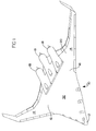
- blended wing-body aircraft 10 having a fuselage 12 and a pair of wings 14.
- Blended wing-body aircraft 10 of the preferred embodiment is characterized by the smooth shallow curve formed by the exterior structural panels between fuselage 12 and wings 14. Unlike conventional aircraft designs, blended wing-body aircraft 10 has no discrete interface between fuselage 12 and wings 14. The exterior skin of fuselage 12 and wings 14 join together to form a blended region 16. Fuselage 12, wings 14, and blended region 16 cooperate to define a substantially uninterrupted wing member capable of providing aerodynamic lift to blended wing-body aircraft 10 according to known aerodynamic principles.
- Blended wing-body aircraft 10 further includes a plurality of turbofan propulsion engines 18. As illustrated in the figures, the presently preferred embodiment includes three turbofan propulsion engines 18 generally mounted to an aft region 20 of blended wing-body aircraft 10. It should be appreciated, however, that the principles of the present invention may be employed in aircraft having any number of engines.
- turbofan propulsion engine 18 served by the presently preferred embodiment is a turbofan-type jet engine.
- turbofan propulsion engine 18 includes an aft-mounted bypass fan section 22 and a turbine section 24.
- Turbine section 24 is disposed concentrically within bypass fan section 22.
- Turbine section 24 generally includes a compressor casing 28 and an exhaust nozzle 30.
- a turbine rotor 31 is operably mounted within compressor casing 28 and is mechanically linked to a compressor 32.
- Compressor 32 is disposed within a compressor casing 28.
- a rear cone 34 is mounted within exhaust nozzle 30 so as to provide proper thrust flow from turbofan propulsion engine 18.
- Bypass fan section 22 includes a plurality of fan blades 21 in a fan casing 38 so as to provide "cold" flow thrust from outlet 40 of bypass fan section 22.
- feed air is supplied to turbofan propulsion engine 18 via a dual boundary layer engine inlet system 42.
- Engine inlet system 42 includes a compressor air inlet duct 44 and a bypass air duct 46.
- bypass air duct 46 includes an inlet end 48 and an outlet end 50.
- inlet end 48 of bypass air duct 46 is generally rectangular in shape such that it is positioned and substantially follows the curvature of an upper surface 52 of blended wing-body aircraft 10. It should be understood that upper surface 52 of blended wing-body aircraft and, consequently, inlet end 48 of bypass air duct 46 may include any inlet end profile that is conducive to the curvature shape of the aircraft or other aerodynamic requirements.
- Outlet end 50 of bypass air duct 46 is generally circular in cross-section so as to provide a proper fit with an inlet end 54 of bypass fan section 22 of turbofan propulsion engine 18. Therefore, bypass air duct 46 includes a generally complex three-dimensional transition from the generally rectangular inlet end 48 to the generally circular outlet end 50.
- Compressor air inlet duct 44 of engine inlet system 42 is generally S-shaped having an inlet end 56 and an outlet end 58.
- Inlet end 56 of compressor air inlet duct 44 is generally semi-circular in shape (FIG. 3) and is positioned on top of or in a "piggy-back" position relative to bypass air duct 46. That is, a generally flat surface 60 of inlet end 56 of compressor air inlet duct 44 is positioned upon a corresponding top surface 62 of bypass air duct 46.
- Outlet end 58 of air inlet duct 44 is generally circular in shape and of sufficient size so as to be coupled to an inlet end 64 of compressor casing 28.
- a grid 61 serves as a trap for moisture and foreign objects, before the boundary layer air enters the compressor air inlet duct.
- air inlet duct 44 is positioned within a more high energy free-stream air. Accordingly, during flight, boundary layer air, generally indicated at 66 (FIG. 2), flows over upper surface 52 of blended wing-body aircraft 10. Inlet end 48 of bypass air duct 46 is generally disposed within this boundary layer air 66 so as to provide fluid communication of boundary layer air 66 to bypass fan section 22 of turbofan propulsion engine 18.
- bypass fan 21 in bypass fan section 22 produces a reduced pressure at inlet end 54 of bypass fan section 22.
- This reduced pressure condition further exists within bypass air duct 46 and serves to scavenge the flow of boundary layer air 66 over upper surface 52 of blended wing-body aircraft 10. That is, the reduced pressure condition within bypass air duct 46 helps to enhance or promote the flow of boundary layer air 66 over a larger longitudinal portion of upper surface 52 relative to aircraft of conventional design not utilizing this reduced pressure condition.
- inlet end 56 of turbine air duct 44 is positioned substantially above boundary layer air 66 (FIG. 2) and, thus, is open to free-stream air, generally indicated at 68.
- free-stream air 68 is supplied to inlet end 56 of compressor inlet 58.
- free-stream air serves to improve the engine efficiency of known jet propulsion engines.
- the dual boundary layer engine inlet system provides a number of aerodynamic and commercial advantages.
- the dual boundary layer, engine inlet system of the present invention provides a method of supplying high energy free-stream air to the engine's compressor inlet while, simultaneously, supplying boundary layer air to a bypass fan inlet.
- the bypass fan produces reduced pressure that scavenges and promotes the attached relationship of the boundary layer air to the aircraft lift surfaces.
- the dual boundary layer engine inlet system of the present invention enables the aft mounting of the turbofan propulsion engines so as to facilitate simple and convenient repair and/or maintenance in a commercial environment. Simple and convenient repair and maintenance of the jet engines is a prerequisite to commercial viability within the passenger and military transport arenas.
Landscapes
- Engineering & Computer Science (AREA)
- Chemical & Material Sciences (AREA)
- Combustion & Propulsion (AREA)
- Mechanical Engineering (AREA)
- General Engineering & Computer Science (AREA)
- Aviation & Aerospace Engineering (AREA)
- Structures Of Non-Positive Displacement Pumps (AREA)
- Jet Pumps And Other Pumps (AREA)
- Means For Warming Up And Starting Carburetors (AREA)
- Percussion Or Vibration Massage (AREA)
Abstract
Description
Claims (20)
- An engine inlet assembly for a jet propulsion engine of an aircraft, said engine inlet assembly comprising:a first air inlet being positioned generally within a boundary layer flowing around an exterior surface of the aircraft;a first passage fluidly interconnecting said first air inlet and the jet propulsion engine;a second air inlet being positioned generally outside of said boundary layer; anda second passage fluidly interconnecting said second air inlet and the jet propulsion engine.
- The engine inlet assembly according to Claim 1 wherein said first air inlet cooperates with the jet propulsion engine to produce a reduced pressure generally adjacent said exterior surface, said reduced pressure generally promotes attachment of said boundary layer to said exterior surface for aircraft drag reduction.
- The engine inlet assembly according to Claim 1 wherein said second air inlet generally provides unobstructed air flow to the jet propulsion engine.
- The engine inlet assembly according to Claim 1 wherein said second passage is generally S-shaped.
- The engine inlet assembly according to Claim 1 wherein said first air inlet is generally rectangular, said first air inlet being positionable generally flush on said exterior surface of the aircraft; and
said second air inlet is generally semi-circular, said second air inlet being generally positioned in piggyback relationship with said first air inlet. - The engine inlet assembly according to Claim 1 wherein said first passage includes an outlet end being in fluid communication with said jet propulsion engine; and
said second passage includes an outlet end being in fluid communication with said jet propulsion engine, said outlet end of said second passage being generally positioned in concentric relationship with said outlet end of said first passage. - The engine inlet assembly according to Claim 1, further comprising:a grid member mounted to said first air inlet to minimize entry of moisture and foreign objects into said first passageway.
- An aircraft having an exterior body surface, said aircraft comprising:a jet engine;a first air inlet passage providing fluid communication between a portion of a boundary layer of the aircraft and said jet engine; anda second air inlet passage providing fluid communication between an air stream outside said boundary layer and said jet engine.
- The aircraft according to Claim 8 wherein:said jet engine is a turbofan type jet engine having a core and compressor and a fan;said first air inlet passage being coupled in fluid communication between said portion of said boundary layer and said fan; andsaid second air inlet passage being coupled in fluid communication between said air stream outside said boundary layer and said core and compressor for providing free stream air flow to said core and compressor.
- The aircraft according to Claim 9 wherein said fan produces a reduced pressure within said first air inlet passage for generally promoting attached flow of said boundary layer outside of said turbofan type jet engine for drag reduction.
- The aircraft according to Claim 9 wherein:said first air inlet passage includes an inlet end and an outlet end; andsaid second air inlet passage includes an inlet end and an outlet end, said inlet end of said second air inlet passage being generally positioned in piggyback relationship with said inlet end of said first air inlet passage, said outlet end of said second air inlet passage being generally positioned in concentric relationship with said outlet end of said first air inlet passage.
- The aircraft according to Claim 8 wherein:said first air inlet passage having an inlet end being positionable generally flush on the exterior body surface of the aircraft; andsaid second air inlet passage having an inlet end being generally positioned in piggyback relationship with said inlet end of said first air inlet passage.
- The aircraft according to Claim 8 wherein said jet engine is aft-mounted.
- The aircraft according to Claim 8, further comprising:a grid member mounted to said first air inlet passageway to minimize entry of moisture and foreign objects therein.
- An aircraft having an exterior body surface, said aircraft comprising:a turbofan type jet engine having a core and compressor and a fan;a first air inlet passage providing fluid communication between a portion of a boundary layer of the aircraft and said fan; anda second air inlet passage providing fluid communication between an air stream outside said boundary layer and said turbine for providing free stream air flow to said core and compressor.
- The aircraft according to Claim 15 wherein said fan produces a reduced pressure within said first air inlet passage for generally promoting attached flow of said boundary layer outside of said turbofan type jet engine for drag reduction.
- The aircraft according to Claim 15 wherein:said first air inlet passage includes an inlet end and an outlet end; andsaid second air inlet passage includes an inlet end and an outlet end, said inlet end of said second air inlet passage being generally positioned in piggyback relationship with said inlet end of said first air inlet passage, said outlet end of said second air inlet passage being generally positioned in concentric relationship with said outlet end of said first air inlet passage.
- The aircraft according to Claim 15 wherein:said first air inlet passage having an inlet end being positionable generally flush on the exterior body surface of the aircraft; andsaid second air inlet passage having an inlet end being generally positioned in piggyback relationship with said inlet end of said first air inlet passage.
- The aircraft according to Claim 15 wherein said jet engine is aft-mounted.
- The aircraft according to Claim 15, further comprising:a grid member mounted to said first air inlet passage to minimize entry of moisture and foreign objects therein.
Priority Applications (1)
| Application Number | Priority Date | Filing Date | Title |
|---|---|---|---|
| DE60223439T DE60223439T3 (en) | 2001-03-23 | 2002-02-22 | Double inlet of a jet engine |
Applications Claiming Priority (2)
| Application Number | Priority Date | Filing Date | Title |
|---|---|---|---|
| US816985 | 1977-07-19 | ||
| US09/816,985 US6527224B2 (en) | 2001-03-23 | 2001-03-23 | Separate boundary layer engine inlet |
Publications (4)
| Publication Number | Publication Date |
|---|---|
| EP1243782A2 true EP1243782A2 (en) | 2002-09-25 |
| EP1243782A3 EP1243782A3 (en) | 2005-03-02 |
| EP1243782B1 EP1243782B1 (en) | 2007-11-14 |
| EP1243782B2 EP1243782B2 (en) | 2013-07-10 |
Family
ID=25222095
Family Applications (1)
| Application Number | Title | Priority Date | Filing Date |
|---|---|---|---|
| EP02075713.4A Expired - Lifetime EP1243782B2 (en) | 2001-03-23 | 2002-02-22 | Double jet engine inlet |
Country Status (5)
| Country | Link |
|---|---|
| US (1) | US6527224B2 (en) |
| EP (1) | EP1243782B2 (en) |
| AT (1) | ATE378508T1 (en) |
| DE (1) | DE60223439T3 (en) |
| ES (1) | ES2292685T5 (en) |
Cited By (8)
| Publication number | Priority date | Publication date | Assignee | Title |
|---|---|---|---|---|
| WO2008017567A1 (en) * | 2006-08-11 | 2008-02-14 | Team Smartfish Gmbh | Air inlet for a jet engine |
| GB2461718A (en) * | 2008-07-10 | 2010-01-13 | Rolls Royce Plc | An aircraft propulsion arrangement having a single fan located within a curved guide path |
| FR2938824A1 (en) * | 2008-11-26 | 2010-05-28 | Aircelle Sa | NACELLE INTEGRATED ON FLYING WING |
| WO2011046580A3 (en) * | 2009-09-17 | 2011-07-21 | Moran John P | Bird deflector and air replacement system |
| US20130306024A1 (en) * | 2011-10-05 | 2013-11-21 | Rolls-Royce Plc | Duct |
| CN103950542A (en) * | 2014-04-04 | 2014-07-30 | 张鑫宇 | Drag-reducing wind head |
| CN109720586A (en) * | 2017-10-30 | 2019-05-07 | 成都飞机工业(集团)有限责任公司 | A kind of boundary layer diverter |
| CN110304267A (en) * | 2019-07-19 | 2019-10-08 | 中国人民解放军国防科技大学 | Hypersonic vehicle design method and system |
Families Citing this family (35)
| Publication number | Priority date | Publication date | Assignee | Title |
|---|---|---|---|---|
| US7644888B2 (en) * | 2002-05-15 | 2010-01-12 | The Boeing Company | High-speed aircraft and methods for their manufacture |
| GB0313456D0 (en) * | 2003-06-11 | 2003-07-16 | Rolls Royce Plc | Propulsion arrangement |
| US20060157613A1 (en) * | 2005-01-19 | 2006-07-20 | Adamson Eric E | Supersonic aircraft with active lift distribution control for reducing sonic boom |
| US7721989B2 (en) * | 2006-03-01 | 2010-05-25 | The Boeing Company | Multi-path inlet for aircraft engine |
| US7861968B2 (en) * | 2006-10-26 | 2011-01-04 | The Boeing Company | Air inlet and method for a highspeed mobile platform |
| US7624944B2 (en) * | 2006-10-26 | 2009-12-01 | The Boeing Company | Tandem air inlet apparatus and method for an airborne mobile platform |
| US7665689B2 (en) * | 2006-11-24 | 2010-02-23 | The Boeing Company | Unconventional integrated propulsion systems and methods for blended wing body aircraft |
| US7784732B2 (en) * | 2007-01-04 | 2010-08-31 | The United States Of America As Represented By The Administrator Of The National Aeronautics And Space Administration | Boundary-layer-ingesting inlet flow control system |
| ITTO20080142A1 (en) * | 2008-02-28 | 2009-08-29 | Alenia Aeronautica Spa | AIR INTAKE, IN PARTICULAR FOR A CHAFF EXULSER FOR AIRCRAFT |
| US7793884B2 (en) * | 2008-12-31 | 2010-09-14 | Faruk Dizdarevic | Deltoid main wing aerodynamic configurations |
| US8511603B2 (en) * | 2009-01-14 | 2013-08-20 | Lewis E. Blomeley | Roadable aircraft with collapsible wings and ductless fan |
| US8844262B2 (en) * | 2009-12-29 | 2014-09-30 | Rolls-Royce North American Technologies, Inc. | Exhaust for a gas turbine engine |
| US8056852B1 (en) * | 2011-02-21 | 2011-11-15 | Faruk Dizdarevic | Longitudinal flying wing aircraft |
| US9291101B2 (en) * | 2013-02-28 | 2016-03-22 | United Technologies Corporation | Gas turbine engine inlet wall design |
| US10907544B2 (en) | 2014-03-27 | 2021-02-02 | Raytheon Technologies Corporation | Gas turbine engine inlet wall design |
| US10421553B2 (en) * | 2015-01-20 | 2019-09-24 | United Technologies Corporation | Pusher fan engine with in wing configuration |
| JP6128568B2 (en) * | 2015-03-26 | 2017-05-17 | 株式会社Subaru | Aircraft intake structure |
| US9758253B2 (en) | 2015-06-25 | 2017-09-12 | Northrop Grumman Systems Corporation | Swept gradient boundary layer diverter |
| RU2605653C1 (en) * | 2015-08-28 | 2016-12-27 | Федеральное государственное унитарное предприятие "Центральный институт авиационного моторостроения им. П.И. Баранова" | Method of engine arrangement on "flying wing" type aircraft |
| US10556702B2 (en) * | 2016-07-13 | 2020-02-11 | General Electric Company | Aircraft having an airflow duct |
| US10436055B2 (en) | 2016-12-21 | 2019-10-08 | United Technologies Corporation | Distributed fan lubrication system |
| US10807013B2 (en) | 2017-12-20 | 2020-10-20 | Francis A. Alonso | Modified delta wing kite with inflatable fuselage |
| USD873350S1 (en) * | 2018-08-23 | 2020-01-21 | Francis A. Alonso | Zig-zagged swept wing kite |
| USD875183S1 (en) * | 2018-08-23 | 2020-02-11 | Francis A. Alonso | Zig-zagged swept wing kite |
| USD874578S1 (en) * | 2018-08-23 | 2020-02-04 | Francis A. Alonso | Swept wing kite |
| USD874577S1 (en) * | 2018-08-23 | 2020-02-04 | Francis A. Alonso | Swept wing kite |
| US11124291B2 (en) | 2018-12-13 | 2021-09-21 | Raytheon Technologies Corporation | System to promote accelerated boundary layer ingestion |
| US11247776B2 (en) * | 2019-04-01 | 2022-02-15 | The Boeing Company | Aircraft having embedded engines |
| WO2021007216A1 (en) * | 2019-07-08 | 2021-01-14 | DZYNE Technologies Incorporated | Drag recovery scheme using boundary layer ingestion |
| CN111412066B (en) * | 2020-04-27 | 2023-04-04 | 南昌航空大学 | Three-dimensional inward rotation air inlet channel with annular self-adaptive drainage tube and design method |
| US11767776B2 (en) * | 2020-09-04 | 2023-09-26 | The Boeing Company | Propulsion flow path duct systems and methods |
| US12552534B2 (en) | 2022-04-12 | 2026-02-17 | General Electric Company | Blended wing body aircraft |
| DE102022113595A1 (en) | 2022-05-30 | 2023-11-30 | Reiner Brach | Aircraft for flying in ambient air using dynamic buoyancy |
| US11827339B1 (en) | 2023-01-27 | 2023-11-28 | Jetzero, Inc. | Apparatus for ingesting boundary layer flow for an aircraft |
| CN119305713A (en) * | 2024-11-05 | 2025-01-14 | 中国航空工业集团公司西安飞机设计研究所 | A power device for an aircraft with wing-body fusion layout and a control method thereof |
Family Cites Families (19)
| Publication number | Priority date | Publication date | Assignee | Title |
|---|---|---|---|---|
| US3237891A (en) * | 1964-05-13 | 1966-03-01 | British Aircraft Corp Ltd | Jet-propulsion power-plants for aircraft |
| GB1212875A (en) | 1967-12-21 | 1970-11-18 | Rolls Royce | Aircraft |
| SE318194B (en) | 1968-06-24 | 1969-12-01 | Saab Ab | |
| FR2250671B1 (en) * | 1973-11-09 | 1980-01-04 | Aerospatiale | |
| FR2344445A1 (en) * | 1976-03-16 | 1977-10-14 | Linderoth Hans | Guard for jet engine air inlet - has series of metal or plastic rods in cone to deflect birds from inlet |
| US4176812A (en) | 1977-10-31 | 1979-12-04 | The Boeing Company | Midcabin door for blended wing aircraft |
| US4198018A (en) | 1978-03-13 | 1980-04-15 | The Boeing Company | Blended wing-fuselage frame made of fiber reinforced resin composites |
| US4456204A (en) * | 1981-09-29 | 1984-06-26 | The Boeing Company | Deployable inlet for aeroplane center boost engine |
| US4463772A (en) | 1981-09-29 | 1984-08-07 | The Boeing Company | Flush inlet for supersonic aircraft |
| US4455045A (en) | 1981-10-26 | 1984-06-19 | Wheeler Gary O | Means for maintaining attached flow of a flowing medium |
| DE3811614C1 (en) * | 1988-04-07 | 1989-05-18 | Messerschmitt-Boelkow-Blohm Gmbh, 8012 Ottobrunn, De | |
| US5031859A (en) | 1989-07-26 | 1991-07-16 | Cunningham John T | Lift-producing machine or device |
| US5114097A (en) * | 1991-04-29 | 1992-05-19 | Williams International Corporation | Aircraft |
| US5299760A (en) * | 1992-07-07 | 1994-04-05 | The Dee Howard Company | S-duct for a turbo-jet aircraft engine |
| US5779189A (en) | 1996-03-19 | 1998-07-14 | Lockheed Martin Corporation | System and method for diverting boundary layer air |
| US5848193A (en) | 1997-04-07 | 1998-12-08 | The United States Of America As Represented By The Secretary Of The Navy | Wavelet projection transform features applied to real time pattern recognition |
| US5909858A (en) | 1997-06-19 | 1999-06-08 | Mcdonnell Douglas Corporation | Spanwise transition section for blended wing-body aircraft |
| US5893535A (en) * | 1997-06-19 | 1999-04-13 | Mcdonnell Douglas Corporation | Rib for blended wing-body aircraft |
| US6089504A (en) * | 1997-07-21 | 2000-07-18 | Williams Internaitonal Co., L.L.C. | Single engine aircraft |
-
2001
- 2001-03-23 US US09/816,985 patent/US6527224B2/en not_active Expired - Lifetime
-
2002
- 2002-02-22 ES ES02075713T patent/ES2292685T5/en not_active Expired - Lifetime
- 2002-02-22 AT AT02075713T patent/ATE378508T1/en not_active IP Right Cessation
- 2002-02-22 DE DE60223439T patent/DE60223439T3/en not_active Expired - Lifetime
- 2002-02-22 EP EP02075713.4A patent/EP1243782B2/en not_active Expired - Lifetime
Cited By (11)
| Publication number | Priority date | Publication date | Assignee | Title |
|---|---|---|---|---|
| WO2008017567A1 (en) * | 2006-08-11 | 2008-02-14 | Team Smartfish Gmbh | Air inlet for a jet engine |
| GB2461718A (en) * | 2008-07-10 | 2010-01-13 | Rolls Royce Plc | An aircraft propulsion arrangement having a single fan located within a curved guide path |
| FR2938824A1 (en) * | 2008-11-26 | 2010-05-28 | Aircelle Sa | NACELLE INTEGRATED ON FLYING WING |
| WO2010061071A3 (en) * | 2008-11-26 | 2010-10-07 | Aircelle | Nacelle integrated on a flying wing |
| WO2011046580A3 (en) * | 2009-09-17 | 2011-07-21 | Moran John P | Bird deflector and air replacement system |
| GB2485312A (en) * | 2009-09-17 | 2012-05-09 | John P Moran | Bird deflector and air replacement system |
| US20130306024A1 (en) * | 2011-10-05 | 2013-11-21 | Rolls-Royce Plc | Duct |
| CN103950542A (en) * | 2014-04-04 | 2014-07-30 | 张鑫宇 | Drag-reducing wind head |
| CN109720586A (en) * | 2017-10-30 | 2019-05-07 | 成都飞机工业(集团)有限责任公司 | A kind of boundary layer diverter |
| CN110304267A (en) * | 2019-07-19 | 2019-10-08 | 中国人民解放军国防科技大学 | Hypersonic vehicle design method and system |
| CN110304267B (en) * | 2019-07-19 | 2020-08-11 | 中国人民解放军国防科技大学 | Hypersonic aircraft design method and system |
Also Published As
| Publication number | Publication date |
|---|---|
| EP1243782B1 (en) | 2007-11-14 |
| ES2292685T3 (en) | 2008-03-16 |
| DE60223439T2 (en) | 2008-10-02 |
| EP1243782A3 (en) | 2005-03-02 |
| US20020134886A1 (en) | 2002-09-26 |
| ES2292685T5 (en) | 2013-11-14 |
| ATE378508T1 (en) | 2007-11-15 |
| US6527224B2 (en) | 2003-03-04 |
| DE60223439T3 (en) | 2013-12-12 |
| DE60223439D1 (en) | 2007-12-27 |
| EP1243782B2 (en) | 2013-07-10 |
Similar Documents
| Publication | Publication Date | Title |
|---|---|---|
| US6527224B2 (en) | Separate boundary layer engine inlet | |
| CN107521705B (en) | Assembly for an aircraft comprising an engine with boundary layer suction propulsion | |
| US7665689B2 (en) | Unconventional integrated propulsion systems and methods for blended wing body aircraft | |
| EP2084061B1 (en) | Supersonic aircraft jet engine | |
| US4722357A (en) | Gas turbine engine nacelle | |
| US6216982B1 (en) | Suction device for boundary layer control in an aircraft | |
| US20230021836A1 (en) | Unducted thrust producing system | |
| US9587585B1 (en) | Augmented propulsion system with boundary layer suction and wake blowing | |
| US20130336781A1 (en) | Aircraft | |
| JPH0350100A (en) | Hybrid laminar flow nacelle | |
| EP3351475B1 (en) | Nacelle for an aircraft aft fan | |
| EP3623279A1 (en) | Ported shroud system for turboprop inlets | |
| CA1263242A (en) | Gas turbine outlet arrangement | |
| US20110240804A1 (en) | Integrated aircraft | |
| US20130134265A1 (en) | Aircraft | |
| EP3428436B1 (en) | Aircraft incorporating a thrust recovery system using cabin air | |
| CN218463882U (en) | Engine nacelle for power influence of turboprop aircraft | |
| US12202602B2 (en) | Fluid systems having a variable configuration | |
| CN106286010A (en) | A kind of gear drive fanjet of reverse installation core engine | |
| EP3650342B1 (en) | Supersonic jet aircraft | |
| US20160144972A1 (en) | Blended Wing Body Boundary Layer Ingesting Inlet Design Integration | |
| RU2003125378A (en) | INTEGRAL AND / OR MODULAR HIGH SPEED AIRCRAFT | |
| CN224117524U (en) | A nacelle unit, a distributed propulsion nacelle, and a new energy aircraft | |
| RU2838700C1 (en) | Long-haul aircraft with hybrid power plant | |
| WO2024095581A1 (en) | Tail-integrated boundary-layer ingesting propulsion |
Legal Events
| Date | Code | Title | Description |
|---|---|---|---|
| PUAI | Public reference made under article 153(3) epc to a published international application that has entered the european phase |
Free format text: ORIGINAL CODE: 0009012 |
|
| AK | Designated contracting states |
Kind code of ref document: A2 Designated state(s): AT BE CH CY DE DK ES FI FR GB GR IE IT LI LU MC NL PT SE TR |
|
| AX | Request for extension of the european patent |
Free format text: AL;LT;LV;MK;RO;SI |
|
| PUAL | Search report despatched |
Free format text: ORIGINAL CODE: 0009013 |
|
| AK | Designated contracting states |
Kind code of ref document: A3 Designated state(s): AT BE CH CY DE DK ES FI FR GB GR IE IT LI LU MC NL PT SE TR |
|
| AX | Request for extension of the european patent |
Extension state: AL LT LV MK RO SI |
|
| RIC1 | Information provided on ipc code assigned before grant |
Ipc: 7F 02K 1/38 A Ipc: 7B 64D 33/02 B Ipc: 7F 02C 7/04 B |
|
| 17P | Request for examination filed |
Effective date: 20050902 |
|
| AKX | Designation fees paid |
Designated state(s): AT BE CH CY DE DK ES FI FR GB GR IE IT LI LU MC NL PT SE TR |
|
| GRAP | Despatch of communication of intention to grant a patent |
Free format text: ORIGINAL CODE: EPIDOSNIGR1 |
|
| GRAS | Grant fee paid |
Free format text: ORIGINAL CODE: EPIDOSNIGR3 |
|
| 17Q | First examination report despatched |
Effective date: 20060202 |
|
| GRAA | (expected) grant |
Free format text: ORIGINAL CODE: 0009210 |
|
| AK | Designated contracting states |
Kind code of ref document: B1 Designated state(s): AT BE CH CY DE DK ES FI FR GB GR IE IT LI LU MC NL PT SE TR |
|
| REG | Reference to a national code |
Ref country code: GB Ref legal event code: FG4D |
|
| REG | Reference to a national code |
Ref country code: CH Ref legal event code: EP |
|
| REG | Reference to a national code |
Ref country code: IE Ref legal event code: FG4D |
|
| REF | Corresponds to: |
Ref document number: 60223439 Country of ref document: DE Date of ref document: 20071227 Kind code of ref document: P |
|
| REG | Reference to a national code |
Ref country code: ES Ref legal event code: FG2A Ref document number: 2292685 Country of ref document: ES Kind code of ref document: T3 |
|
| PG25 | Lapsed in a contracting state [announced via postgrant information from national office to epo] |
Ref country code: SE Free format text: LAPSE BECAUSE OF FAILURE TO SUBMIT A TRANSLATION OF THE DESCRIPTION OR TO PAY THE FEE WITHIN THE PRESCRIBED TIME-LIMIT Effective date: 20080214 Ref country code: NL Free format text: LAPSE BECAUSE OF FAILURE TO SUBMIT A TRANSLATION OF THE DESCRIPTION OR TO PAY THE FEE WITHIN THE PRESCRIBED TIME-LIMIT Effective date: 20071114 Ref country code: CH Free format text: LAPSE BECAUSE OF FAILURE TO SUBMIT A TRANSLATION OF THE DESCRIPTION OR TO PAY THE FEE WITHIN THE PRESCRIBED TIME-LIMIT Effective date: 20071114 Ref country code: LI Free format text: LAPSE BECAUSE OF FAILURE TO SUBMIT A TRANSLATION OF THE DESCRIPTION OR TO PAY THE FEE WITHIN THE PRESCRIBED TIME-LIMIT Effective date: 20071114 |
|
| NLV1 | Nl: lapsed or annulled due to failure to fulfill the requirements of art. 29p and 29m of the patents act | ||
| REG | Reference to a national code |
Ref country code: CH Ref legal event code: PL |
|
| PG25 | Lapsed in a contracting state [announced via postgrant information from national office to epo] |
Ref country code: AT Free format text: LAPSE BECAUSE OF FAILURE TO SUBMIT A TRANSLATION OF THE DESCRIPTION OR TO PAY THE FEE WITHIN THE PRESCRIBED TIME-LIMIT Effective date: 20071114 |
|
| ET | Fr: translation filed | ||
| PG25 | Lapsed in a contracting state [announced via postgrant information from national office to epo] |
Ref country code: DK Free format text: LAPSE BECAUSE OF FAILURE TO SUBMIT A TRANSLATION OF THE DESCRIPTION OR TO PAY THE FEE WITHIN THE PRESCRIBED TIME-LIMIT Effective date: 20071114 |
|
| PLBI | Opposition filed |
Free format text: ORIGINAL CODE: 0009260 |
|
| PG25 | Lapsed in a contracting state [announced via postgrant information from national office to epo] |
Ref country code: BE Free format text: LAPSE BECAUSE OF FAILURE TO SUBMIT A TRANSLATION OF THE DESCRIPTION OR TO PAY THE FEE WITHIN THE PRESCRIBED TIME-LIMIT Effective date: 20071114 |
|
| 26 | Opposition filed |
Opponent name: AIRBUS SAS/AIRBUS FRANCE/AIRBUS UK LIMITED AIRBUS Effective date: 20080805 |
|
| PLAX | Notice of opposition and request to file observation + time limit sent |
Free format text: ORIGINAL CODE: EPIDOSNOBS2 |
|
| PG25 | Lapsed in a contracting state [announced via postgrant information from national office to epo] |
Ref country code: PT Free format text: LAPSE BECAUSE OF FAILURE TO SUBMIT A TRANSLATION OF THE DESCRIPTION OR TO PAY THE FEE WITHIN THE PRESCRIBED TIME-LIMIT Effective date: 20080414 |
|
| PG25 | Lapsed in a contracting state [announced via postgrant information from national office to epo] |
Ref country code: MC Free format text: LAPSE BECAUSE OF NON-PAYMENT OF DUE FEES Effective date: 20080228 |
|
| PG25 | Lapsed in a contracting state [announced via postgrant information from national office to epo] |
Ref country code: IE Free format text: LAPSE BECAUSE OF NON-PAYMENT OF DUE FEES Effective date: 20080222 Ref country code: GR Free format text: LAPSE BECAUSE OF FAILURE TO SUBMIT A TRANSLATION OF THE DESCRIPTION OR TO PAY THE FEE WITHIN THE PRESCRIBED TIME-LIMIT Effective date: 20080215 |
|
| PLBB | Reply of patent proprietor to notice(s) of opposition received |
Free format text: ORIGINAL CODE: EPIDOSNOBS3 |
|
| PG25 | Lapsed in a contracting state [announced via postgrant information from national office to epo] |
Ref country code: CY Free format text: LAPSE BECAUSE OF FAILURE TO SUBMIT A TRANSLATION OF THE DESCRIPTION OR TO PAY THE FEE WITHIN THE PRESCRIBED TIME-LIMIT Effective date: 20071114 |
|
| PG25 | Lapsed in a contracting state [announced via postgrant information from national office to epo] |
Ref country code: FI Free format text: LAPSE BECAUSE OF FAILURE TO SUBMIT A TRANSLATION OF THE DESCRIPTION OR TO PAY THE FEE WITHIN THE PRESCRIBED TIME-LIMIT Effective date: 20071114 |
|
| PG25 | Lapsed in a contracting state [announced via postgrant information from national office to epo] |
Ref country code: LU Free format text: LAPSE BECAUSE OF NON-PAYMENT OF DUE FEES Effective date: 20080222 |
|
| PG25 | Lapsed in a contracting state [announced via postgrant information from national office to epo] |
Ref country code: TR Free format text: LAPSE BECAUSE OF FAILURE TO SUBMIT A TRANSLATION OF THE DESCRIPTION OR TO PAY THE FEE WITHIN THE PRESCRIBED TIME-LIMIT Effective date: 20071114 |
|
| PG25 | Lapsed in a contracting state [announced via postgrant information from national office to epo] |
Ref country code: IT Free format text: LAPSE BECAUSE OF NON-PAYMENT OF DUE FEES Effective date: 20080229 |
|
| PUAH | Patent maintained in amended form |
Free format text: ORIGINAL CODE: 0009272 |
|
| STAA | Information on the status of an ep patent application or granted ep patent |
Free format text: STATUS: PATENT MAINTAINED AS AMENDED |
|
| 27A | Patent maintained in amended form |
Effective date: 20130710 |
|
| AK | Designated contracting states |
Kind code of ref document: B2 Designated state(s): AT BE CH CY DE DK ES FI FR GB GR IE IT LI LU MC NL PT SE TR |
|
| REG | Reference to a national code |
Ref country code: DE Ref legal event code: R102 Ref document number: 60223439 Country of ref document: DE |
|
| REG | Reference to a national code |
Ref country code: DE Ref legal event code: R102 Ref document number: 60223439 Country of ref document: DE Effective date: 20130710 |
|
| REG | Reference to a national code |
Ref country code: ES Ref legal event code: DC2A Ref document number: 2292685 Country of ref document: ES Kind code of ref document: T5 Effective date: 20131114 |
|
| REG | Reference to a national code |
Ref country code: DE Ref legal event code: R081 Ref document number: 60223439 Country of ref document: DE Owner name: THE BOEING COMPANY, US Free format text: FORMER OWNER: THE BOEING COMPANY, SEATTLE, US Effective date: 20140320 Ref country code: DE Ref legal event code: R082 Ref document number: 60223439 Country of ref document: DE Representative=s name: PATENT- UND RECHTSANWAELTE KRAUS & WEISERT, DE Effective date: 20140320 Ref country code: DE Ref legal event code: R081 Ref document number: 60223439 Country of ref document: DE Owner name: THE BOEING COMPANY, CHICAGO, US Free format text: FORMER OWNER: THE BOEING COMPANY, SEATTLE, WASH., US Effective date: 20140320 Ref country code: DE Ref legal event code: R082 Ref document number: 60223439 Country of ref document: DE Representative=s name: KRAUS & WEISERT PATENTANWAELTE PARTGMBB, DE Effective date: 20140320 |
|
| REG | Reference to a national code |
Ref country code: FR Ref legal event code: PLFP Year of fee payment: 15 |
|
| REG | Reference to a national code |
Ref country code: FR Ref legal event code: PLFP Year of fee payment: 16 |
|
| REG | Reference to a national code |
Ref country code: FR Ref legal event code: PLFP Year of fee payment: 17 |
|
| PGFP | Annual fee paid to national office [announced via postgrant information from national office to epo] |
Ref country code: GB Payment date: 20200227 Year of fee payment: 19 Ref country code: DE Payment date: 20200227 Year of fee payment: 19 Ref country code: ES Payment date: 20200302 Year of fee payment: 19 |
|
| PGFP | Annual fee paid to national office [announced via postgrant information from national office to epo] |
Ref country code: FR Payment date: 20200225 Year of fee payment: 19 |
|
| REG | Reference to a national code |
Ref country code: DE Ref legal event code: R119 Ref document number: 60223439 Country of ref document: DE |
|
| GBPC | Gb: european patent ceased through non-payment of renewal fee |
Effective date: 20210222 |
|
| PG25 | Lapsed in a contracting state [announced via postgrant information from national office to epo] |
Ref country code: DE Free format text: LAPSE BECAUSE OF NON-PAYMENT OF DUE FEES Effective date: 20210901 Ref country code: FR Free format text: LAPSE BECAUSE OF NON-PAYMENT OF DUE FEES Effective date: 20210228 Ref country code: GB Free format text: LAPSE BECAUSE OF NON-PAYMENT OF DUE FEES Effective date: 20210222 |
|
| REG | Reference to a national code |
Ref country code: ES Ref legal event code: FD2A Effective date: 20220513 |
|
| PG25 | Lapsed in a contracting state [announced via postgrant information from national office to epo] |
Ref country code: ES Free format text: LAPSE BECAUSE OF NON-PAYMENT OF DUE FEES Effective date: 20210223 |