EP1243541A2 - Sheet discharge apparatus including pressing member for giving wavy shape to sheet and image forming apparatus including the same - Google Patents
Sheet discharge apparatus including pressing member for giving wavy shape to sheet and image forming apparatus including the same Download PDFInfo
- Publication number
- EP1243541A2 EP1243541A2 EP02006554A EP02006554A EP1243541A2 EP 1243541 A2 EP1243541 A2 EP 1243541A2 EP 02006554 A EP02006554 A EP 02006554A EP 02006554 A EP02006554 A EP 02006554A EP 1243541 A2 EP1243541 A2 EP 1243541A2
- Authority
- EP
- European Patent Office
- Prior art keywords
- sheet
- gate
- passage
- guide
- pressing means
- Prior art date
- Legal status (The legal status is an assumption and is not a legal conclusion. Google has not performed a legal analysis and makes no representation as to the accuracy of the status listed.)
- Granted
Links
Images


Classifications
-
- B—PERFORMING OPERATIONS; TRANSPORTING
- B65—CONVEYING; PACKING; STORING; HANDLING THIN OR FILAMENTARY MATERIAL
- B65H—HANDLING THIN OR FILAMENTARY MATERIAL, e.g. SHEETS, WEBS, CABLES
- B65H29/00—Delivering or advancing articles from machines; Advancing articles to or into piles
- B65H29/58—Article switches or diverters
- B65H29/60—Article switches or diverters diverting the stream into alternative paths
-
- B—PERFORMING OPERATIONS; TRANSPORTING
- B65—CONVEYING; PACKING; STORING; HANDLING THIN OR FILAMENTARY MATERIAL
- B65H—HANDLING THIN OR FILAMENTARY MATERIAL, e.g. SHEETS, WEBS, CABLES
- B65H29/00—Delivering or advancing articles from machines; Advancing articles to or into piles
- B65H29/70—Article bending or stiffening arrangements
-
- B—PERFORMING OPERATIONS; TRANSPORTING
- B65—CONVEYING; PACKING; STORING; HANDLING THIN OR FILAMENTARY MATERIAL
- B65H—HANDLING THIN OR FILAMENTARY MATERIAL, e.g. SHEETS, WEBS, CABLES
- B65H2404/00—Parts for transporting or guiding the handled material
- B65H2404/10—Rollers
- B65H2404/13—Details of longitudinal profile
- B65H2404/133—Limited number of active elements on common axis
-
- B—PERFORMING OPERATIONS; TRANSPORTING
- B65—CONVEYING; PACKING; STORING; HANDLING THIN OR FILAMENTARY MATERIAL
- B65H—HANDLING THIN OR FILAMENTARY MATERIAL, e.g. SHEETS, WEBS, CABLES
- B65H2404/00—Parts for transporting or guiding the handled material
- B65H2404/10—Rollers
- B65H2404/14—Roller pairs
- B65H2404/144—Roller pairs with relative movement of the rollers to / from each other
- B65H2404/1441—Roller pairs with relative movement of the rollers to / from each other involving controlled actuator
-
- B—PERFORMING OPERATIONS; TRANSPORTING
- B65—CONVEYING; PACKING; STORING; HANDLING THIN OR FILAMENTARY MATERIAL
- B65H—HANDLING THIN OR FILAMENTARY MATERIAL, e.g. SHEETS, WEBS, CABLES
- B65H2404/00—Parts for transporting or guiding the handled material
- B65H2404/60—Other elements in face contact with handled material
- B65H2404/63—Oscillating, pivoting around an axis parallel to face of material, e.g. diverting means
-
- B—PERFORMING OPERATIONS; TRANSPORTING
- B65—CONVEYING; PACKING; STORING; HANDLING THIN OR FILAMENTARY MATERIAL
- B65H—HANDLING THIN OR FILAMENTARY MATERIAL, e.g. SHEETS, WEBS, CABLES
- B65H2511/00—Dimensions; Position; Numbers; Identification; Occurrences
- B65H2511/10—Size; Dimensions
- B65H2511/17—Deformation, e.g. stretching
-
- B—PERFORMING OPERATIONS; TRANSPORTING
- B65—CONVEYING; PACKING; STORING; HANDLING THIN OR FILAMENTARY MATERIAL
- B65H—HANDLING THIN OR FILAMENTARY MATERIAL, e.g. SHEETS, WEBS, CABLES
- B65H2513/00—Dynamic entities; Timing aspects
- B65H2513/40—Movement
- B65H2513/42—Route, path
Definitions
- the present invention relates to a sheet discharge apparatus for giving a wavy shape to a sheet and discharging the sheet, and an image forming apparatus with the sheet discharge apparatus mounted thereon, such as a laser printer or copying machine.
- An image forming apparatus such as a laser printer includes: an image processing mechanism for forming an image on a recording sheet; a conveyance passage for conveying the recording sheet with the image formed thereon; and a stacker for accumulating the recording sheets discharged from the conveyance passage.
- the image processing mechanism, conveyance passage and stacker are incorporated in a box-shaped apparatus body.
- the recording sheets discharged from the conveyance passage are successively stacked and stored in the stacker.
- the recording sheet is thin and soft, and therefore inevitably curled, warped and deformed in the process of formation of the image or conveyance through the conveyance passage.
- the recording sheets discharged from the conveyance passage are deformed in this manner, and stacked up in the stacker, the recording sheets are sometimes not aligned.
- the recording sheets are stacked up on the stacker in a disorderly manner, therefore look untidy, and cannot easily be removed from the stacker.
- a so-called in-body discharge type in which a space for discharging the sheets is secured inside the apparatus body.
- the space for discharging the sheets is connected to the downstream end of the conveyance passage, and opened to the outside of the apparatus body.
- a pair of stackers, and a separator unit for distributing the recording sheet to either one of the stackers are disposed in the space.
- the stackers are stacked up and disposed in the height direction of the apparatus body.
- the lower stacker is disposed in a position lower than the downstream end of the conveyance passage.
- the upper stacker is disposed in a position higher than the downstream end of the conveyance passage.
- the separator unit includes a gate for switching the discharge direction of the recording sheet, and a guide passage connected to the upper stacker.
- the gate can be rotated between a first changeover position and a second changeover position.
- the recording sheet discharged in a horizontal direction from the conveyance passage is guided into the lower stacker.
- the gate is rotated into the second changeover position, the recording sheet is guided into the guide passage via the gate.
- the guide passage guides the recording sheet discharged from the conveyance passage to the upper stacker. Therefore, the guide passage extends in a vertical direction, and has two corner portions midway.
- One corner portion is positioned in the upstream end of the guide passage, and guides upwards the recording sheet discharged in the horizontal direction from the conveyance passage.
- the other corner portion is positioned in the downstream end of the guide passage, and guides the recording sheet conveyed upwards along the guide passage horizontally toward the upper stacker.
- the separator unit needs to be contained in the limited space of the apparatus body, particularly the total length of the guide passage is shortened. As a result, two corner portions for changing the conveyance direction of the recording sheet are disposed in the vicinity of each other, and the guide passage is steeply bent in a crank shape. Therefore, the recording sheet is forcibly bent twice while passed through the guide passage.
- the recording sheet is pressed by the plurality of rollers and waved before being guided into the guide passage.
- a force for forcibly deforming the sheet is applied to the temporarily rigid recording sheet.
- the recording sheet generates a harsh sound as if something were broken. This abnormal sound makes a noise, and may discomfort the operator.
- the force for forcibly stretching the sheet flat is applied to the waved recording sheet.
- the recording sheet is not smoothly conveyed, and therefore wrinkled, and jamming is caused.
- Jpn. Pat. Appln. KOKAI Publication No. 6-239002 discloses an improvement in waving the recording sheet discharged from the conveyance passage.
- a hump member for pressing the recording sheet is disposed in the downstream end of the conveyance passage.
- the hump member can selectively move to a raised position or a lowered position.
- the hump member juts out on the conveyance passage, and presses the recording sheet.
- the hump member reaches the lowered position, the hump member retreats from the conveyance passage. Therefore, the recording sheet is discharged from the conveyance passage without being hampered by the hump member.
- a sheet discharge apparatus in which a sorter is selectively connected to the downstream end of the conveyance passage and used there.
- the sorter is detected whether or not the sorter is connected to the downstream end of the conveyance passage, and the hump member is moved in accordance with the detected result. Therefore, in the prior art, the problem of the abnormal sound generated by the recording sheet during the guiding of the waved recording sheet through the bent guide passage is not recognized, and the necessity of muffling the abnormal sound generated by the deformation of the recording sheet is not taught.
- An object of the present invention is to provide a sheet discharge apparatus which can wave a sheet in accordance with a discharge direction of the sheet, and can prevent the sheet being conveyed from making an abnormal sound or from being wrinkled.
- Another object of the present invention is to provide an image forming apparatus including the sheet discharge apparatus which can prevent the sheet being conveyed from making an abnormal sound or from being wrinkled.
- a sheet discharge apparatus comprising: a conveyance passage to convey a sheet; a plurality of stackers on which the sheet discharged from the conveyance passage is stacked; and a gate which changes a discharge direction of the sheet discharged from the conveyance passage.
- the gate can move over a first changeover position to guide the sheet to one stacker, and a second changeover position to guide the sheet to the other stacker.
- the sheet is guided to the other stacker through a guide passage when the gate is moved to the second changeover position.
- the guide passage has a bent shape.
- Pressing means is disposed on an upstream side from the gate along a conveyance direction of the sheet. The pressing means applies a pressure and gives a wavy shape to the sheet, and temporarily makes the sheet rigid, when the gate is moved to the first changeover position.
- an image forming apparatus comprising: an apparatus body in which an image processing mechanism is disposed to form an image on a sheet; a conveyance passage which is disposed in the apparatus body, and through which the sheet with the image formed thereon is conveyed; a plurality of stackers which are disposed in the apparatus body, and on which the sheet discharged from the conveyance passage is stacked; and a gate which changes a discharge direction of the sheet discharged from the conveyance passage.
- the gate can move over a first changeover position to guide the sheet to one stacker, and a second changeover position to guide the sheet to the other stacker.
- the sheet is guided to the other stacker through a guide passage, when the gate is moved to the second changeover position.
- the guide passage has a bent shape.
- Pressing means is disposed on an upstream side from the gate along a conveyance direction of the sheet. The pressing means applies a pressure and gives a wavy shape to the sheet, and temporarily makes the sheet rigid, when the gate is moved to the first changeover position.
- the wave shape is not given to the sheet guided to the guide passage from the conveyance passage. Therefore, the sheet is smoothly conveyed without applying an unnecessary force to the sheet passed through the guide passage.
- a conveyance passage 5 is formed inside the apparatus body 2. Through the conveyance passage 5, the recording paper P is conveyed to the paper discharge chamber 4 from the paper feed cassette 3.
- the conveyance passage 5 extends in the height direction of the apparatus body 2.
- a downstream end of the conveyance passage 5 is connected to the paper discharge chamber 4 via a paper discharge port 6 formed in the apparatus body 2.
- the paper discharge port 6 is positioned in the middle part in the height direction of the paper discharge chamber 4.
- the paper discharge port 6 horizontally extends crossing at right angles to the conveyance direction of the recording paper P.
- a paper feed roller 7, a plurality of conveyance rollers 8 and paper discharge guide 9 are disposed in the conveyance passage 5.
- the paper feed roller 7 feeds out the recording paper P stored in the paper feed cassette 3 sheet by sheet to the conveyance passage 5.
- the conveyance rollers 8 are positioned on the downstream side from the paper feed roller 7 along the conveyance direction of the recording paper P.
- the paper discharge guide 9 horizontally guides the recording paper P conveyed upwards along the conveyance passage 5.
- the paper discharge guide 9 is positioned in an upper end of the conveyance passage 5.
- a photosensor 10 and actuator 11 are attached to the paper discharge guide 9.
- the photosensor 10 optically detects the recording paper P conveyed to the vicinity of a downstream end of the conveyance passage 5.
- the photosensor 10 has a light emitting portion and light receiving portion (not shown).
- the actuator 11 can be rotated to a standby position to advance into the conveyance passage 5, and a detection position to retreat from the conveyance passage 5.
- the actuator 11 has an interceptor 11a which extends toward the photosensor 10. The interceptor 11a retreats from between the light emitting portion and the light receiving portion as long as the actuator 11 is in the standby position.
- the actuator 11 When the recording paper P conveyed through the conveyance passage 5 contacts the actuator 11 in the standby position, the actuator 11 is rotated to the detection position from the standby position. Thereby, the interceptor 11a advances between the light emitting portion and the light receiving portion of the photosensor 10, and intercepts light. As a result, the photosensor 10 optically detects that the recording paper P reaches the downstream end of the conveyance passage 5, and sends a control signal to a controller 12.
- the apparatus body 2 contains an image processing mechanism 14.
- the image processing mechanism 14 forms an image on the recording paper P, and is positioned midway in the conveyance passage 5.
- the image processing mechanism 14 includes a photosensitive drum 15, charging apparatus 16, exposing apparatus 17, developing apparatus 18, transferring apparatus 19, destaticizing apparatus 20 and fixing apparatus 21.
- a roller unit 23 for discharging the sheet is disposed at the downstream end of the conveyance passage 5.
- the roller unit 23 feeds the recording paper P having reached the downstream end of the conveyance passage 5 out to the paper discharge port 6.
- the roller unit 23 includes a first roller group 24 and a second roller group 25.
- the first roller group 24 is constituted of a roller shaft 26 and a plurality of driving rollers 27.
- the roller shaft 26 is horizontally disposed along the paper discharge part 6.
- the roller shaft 26 is rotated by a drive source such as a motor (not shown).
- the driving rollers 27 are supported by the roller shaft 26. These driving rollers 27 are arranged at intervals in an axial direction of the roller shaft 26, and arranged in a row along a direction crossing at right angles to the conveyance direction of the recording paper P.
- the second roller group 25 is positioned under the first roller group 24.
- the second roller group 25 is constituted of a roller shaft 28 and a plurality of driven rollers 29.
- the roller shaft 28 is horizontally disposed along the paper discharge port 6.
- the driven rollers 29 are supported by the roller shaft 28. These driven rollers 29 are arranged at intervals in the axial direction of the roller shaft 28, and contact the driving rollers 27 of the first roller group 24. Therefore, the first and second roller groups 24, 25 hold and convey the recording paper P therebetween.
- the paper discharge chamber 4 of the apparatus body 2 includes a lower discharge tray 31 and upper discharge tray 32 as stackers.
- the lower discharge tray 31 is integrally formed in the bottom of the paper discharge chamber 4, and disposed in a position lower than that of the paper discharge port 6.
- the upper discharge tray 32 is detachably supported by the apparatus body 2.
- the upper discharge tray 32 is disposed above the lower discharge tray 31, and in a position higher than that of the paper discharge port 6.
- a separator unit 33 is disposed in the upper part of the paper discharge chamber 4.
- the separator unit 33 is detachably supported in the apparatus body 2, and positioned above the paper discharge port 6.
- the separator unit 33 includes a conveyance guide 34.
- the conveyance guide 34 is positioned between the upper discharge tray 32 and the paper discharge port 6.
- the conveyance guide 34 has a guide passage 35.
- the guide passage 35 guides the recording paper P discharged from the paper discharge port 6 to the upper discharge tray 32.
- the guide passage 35 is constituted of first and second corner portions 36a, 36b and linear portion 36c.
- the first and second corner portions 36a, 36b are curved in circular arc shapes.
- the first corner portion 36a is positioned in the upstream end of the guide passage 35, and changes the discharge direction of the recording paper P discharged from the paper discharge port 6 to an upward direction.
- the second corner portion 36b is positioned in the downstream end of the guide passage 35, and changes the conveyance direction of the recording paper P conveyed upwards to a horizontal direction.
- the linear portion 36c extends over the first and second corner portions 36a, 36b in the vertical direction. Therefore, the guide passage 35 is bent in a crank shape, and the downstream end thereof is disposed in a position higher than that of the upper discharge tray 32.
- a discharge roller unit 38 is disposed in the downstream end of the guide passage 35.
- the discharge roller unit 38 discharges the recording paper P onto the upper discharge tray 32.
- the discharge roller unit 38 includes a first roller group 39 and second roller group 40.
- the first roller group 39 is constituted of a roller shaft 41 and a plurality of driving rollers 42.
- the roller shaft 41 is supported by the separator unit 33, and horizontally extends along the direction crossing at right angles to the conveyance direction of the recording paper P.
- the roller shaft 41 is rotated by a driving source (not shown) such as a motor.
- the driving rollers 42 are supported by the roller shaft 41. These driving rollers 42 are disposed at intervals in the axial direction of the roller shaft 41.
- the second roller group 40 is positioned on the first roller group 39.
- the second roller group 40 is constituted of a roller shaft 43 and a plurality of driven rollers 44.
- the roller shaft 43 is disposed in parallel to the roller shaft 41.
- the driven rollers 44 are supported by the roller shaft 43. These driven rollers 44 are disposed at intervals in the axial direction of the roller shaft 43, and contact the driving rollers 42 of the first roller group 39. Therefore, the first and second roller groups 39, 40 hold and convey the recording paper P therebetween.
- the separator unit 33 includes a changeover mechanism 46 for changing the discharge direction of the recording paper P discharged from the paper discharge port 6.
- the changeover mechanism 46 includes a support shaft 47 and a plurality of gates 48.
- the support shaft 47 is supported by the separator unit 33, and horizontally extends along the direction crossing at right angles to the conveyance direction of the recording paper P.
- Press levers 49a, 49b are fixed to opposite ends of the support shaft 47.
- the press levers 49a, 49b are disposed in parallel to each other via the support shaft 47.
- the gates 48 are supported by the support shaft 47, and arranged at intervals in the axial direction of the support shaft 47. These gates 48 are positioned opposite the paper discharge port 6 in the upstream end of the guide passage 35.
- the gates 48 have edges 48a disposed opposite the first corner portion 36a of the guide passage 35.
- the edges 48a are curved along the first corner portion 36a in the circular arc shape.
- the gates 48 are rotated to either the first changeover position or the second changeover position.
- FIG. 4 shows that the gates 48 are rotated to the first changeover position.
- the gates 48 In the first changeover position, the gates 48 retreat in the position higher than that of the paper discharge port 6, and the edges 48a are detached from the paper discharge port 6. Therefore, the recording paper P discharged from the paper discharge port 6 passes under the gates 48 and drops onto the lower discharge tray 31.
- FIG. 5 shows that the gates 48 are rotated to the second changeover position.
- the gates 48 jut out under the separator unit 33, and the edges 48a are disposed opposite to the paper discharge port 6. Therefore, the recording paper P discharged from the paper discharge port 6 is guided by the edges 48a of the gates 48 and fed into the guide passage 35 of the separator unit 33.
- the separator unit 33 includes a driving device 50.
- the driving device 50 moves the gates 48 to the second changeover position from the first changeover position or in reverse.
- the driving device 50 includes an L-shaped link 51 and solenoid 52.
- the L-shaped link 51 has a middle portion as a fulcrum, and the middle portion is connected to one end of the support shaft 47.
- the solenoid 52 includes a plunger 53 which operates linearly.
- the plunger 53 is connected to the L-shaped link 51 via an arm 54.
- a connected portion of the L-shaped link 51 and arm 54 is positioned under the support shaft 47.
- the L-shaped link 51 is biased in a counterclockwise direction in FIG. 3 via a pair of return springs 55a, 55b.
- One return spring 55a extends between the L-shaped link 51 and the separator unit 33.
- the other return spring 55b extends between the press lever 49b and the separator unit 33.
- the separator unit 33 includes a press mechanism 60.
- the press mechanism 60 waves the recording paper P discharged from the paper discharge port 6, and temporarily makes the recording paper P rigid.
- the press mechanism 60 is positioned between the gates 48 and the paper discharge port 6.
- the press mechanism 60 includes a first roller group 61 and second roller group 62.
- the first roller group 61 includes a roller shaft 63, a plurality of driven rollers 64 and a plurality of press rollers 65.
- the roller shaft 63 is horizontally disposed along the direction crossing at right angles to the conveyance direction of the recording paper P.
- the roller shaft 63 is supported by the separator unit 33 via a pair of links 66a, 66b.
- the links 66a, 66b are attached to opposite ends of the roller shaft 63.
- These links 66a, 66b have respective pivot shafts 67 apart from the roller shaft 63.
- the pivot shafts 67 are rotatably supported by the separator unit 33.
- the links 66a, 66b can rotate centering on the pivot shafts 67, and are constantly biased downwards via springs (not shown).
- the driven rollers 64 are supported by the roller shaft 63, and disposed at intervals in the axial direction of the roller shaft 63.
- the press rollers 65 are supported by the roller shaft 63, and positioned between the driven rollers 64 disposed adjacent to each other. Therefore, the driven rollers 64 and press rollers 65 are alternately arranged in the direction crossing at right angles to the conveyance direction of the recording paper P.
- press rollers 65 have diameters larger than those of the driven rollers 64. Therefore, the outer peripheral surfaces of the press rollers 65 extends outwards from the outer peripheral surfaces of the driven rollers 64.
- the second roller group 62 is positioned under the first roller group 61.
- the second roller group 62 includes a roller shaft 69, and a plurality of driving rollers 70.
- the roller shaft 69 is supported by the separator unit 33, and disposed in parallel to the roller shaft 63 of the first roller group 61.
- the roller shaft 69 receives the power from a motor (not shown) and rotates.
- the driving rollers 70 are supported by the roller shaft 69. These driving rollers 70 are disposed at intervals in the axial direction of the roller shaft 69, and contact the driven rollers 64 of the first roller group 61 from below. Therefore, when the driving rollers 70 rotate, the driven rollers 64 and press rollers 65 rotate accordingly. As a result, the recording paper P discharged from the paper discharge port 6 is guided between the driving rollers 70 and the driven rollers 64, held between the rollers 70 and 64, and fed into the paper discharge chamber 4.
- the outer peripheral surfaces of the press rollers 65 jut out downwards from the contact portions of the driven rollers 64 and driving rollers 70. Therefore, the press rollers 65 are pressed onto a plurality of portions of the recording paper P. Thereby, a downward pressure is applied to the recording paper P, and a wavy shape is given to the recording paper P.
- the links 66a, 66b supporting the roller shaft 63 are positioned under the press levers 49a, 49b.
- the ends of the links 66a, 66b opposite the roller shaft 63 are constantly pressed onto the press levers 49a, 49b by spring forces of the springs.
- the press levers 49a, 49b rotate in the counterclockwise direction of FIG. 3 via the support shaft 47.
- the contact portions of the press levers 49a, 49b and links 66a, 66b are moved to positions higher than the positions of the pivot shafts 67, and the links 66a, 66b rotate in the clockwise direction.
- the first roller group 61 moves to a press position in which the press rollers 65 are pressed onto the recording paper P. Therefore, as long as the gates 48 are in the first changeover position, the press rollers 65 wave the recording paper P discharged from the paper discharge port 6.
- the press rollers 65 follow the movement of the gates 48 and are moved to either the press position or the press release position.
- the press levers 49a, 49b and links 66a, 66b constitute cooperation means for transmitting the movement of the gates 48 to the press rollers 65.
- the first roller group 39 of the discharge roller unit 38 has a plurality of press rollers 72 as another press mechanism.
- the press rollers 72 are positioned in the downstream end of the guide passage 35. These press rollers 72 are supported by the roller shaft 41, and positioned between the driving rollers 42 disposed adjacent to each other. Therefore, the driving rollers 42 and press rollers 72 are alternately arranged in the direction crossing at right angles to the conveyance direction of the recording paper P.
- the press rollers 72 have diameters larger than those of the driving rollers 42.
- the outer peripheral surfaces of the press rollers 72 jut out from the outer peripheral surfaces of the driving rollers 42. Therefore, when the recording paper P is discharged onto the upper discharge tray 32 from the guide passage 35, the press rollers 72 are pressed onto the plurality of portions of the recording paper P from below. Thereby, an upward pressure is applied to the recording paper P, and a wavy shape is given to the recording paper P.
- the press mechanism 60 is attached to the separator unit 33. Therefore, when the separator unit 33 is detached from the apparatus body 2, the recording paper P discharged from the paper discharge port 6 cannot be waved.
- a mechanism for waving the recording paper P is added to the roller unit 23 positioned in the downstream end of the conveyance passage 5.
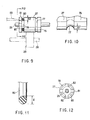
- FIGS. 6 to 12 show details of the first roller group 24 of the roller unit 23.
- the driving rollers 27 of the first roller group 24 some specified ones have portion 76 that extends in the axial direction.
- the extended portions 76 are disconnected from the driven rollers 29, and disposed opposite to the roller shaft 28 which supports the driven rollers 29.
- First attachment grooves 77 and a second attachment grooves 78 are formed in the outer peripheral surfaces of the driving rollers 27.
- the first and second attachment grooves 77, 78 are continuous in a peripheral direction of the driving rollers 27, and are disposed apart from each other in the axial direction of the driving rollers 27.
- the first attachment grooves 77 are positioned in the extended portions 76 of the driving rollers 27.
- Depth dimensions D1 of the first attachment grooves 77 are smaller than depth dimensions D2 of the second attachment grooves 78.
- O rings 80 as press members are attached to the first attachment groove 77 or second attachment groove 78.
- the O rings 80 are constituted of elastically deformable rubber materials.
- inner diameters of the O rings 80 are substantially equal to the diameters of the bottom portions of the second attachment grooves 78. Furthermore, linear diameters d of the O rings 80 are larger than the depth dimensions D1 of the first attachment grooves 77, and smaller than the depth dimensions D2 of the second attachment grooves 78.
- the O rings 80 can selectively moved over a first position in which the rings are attached to the first attachment grooves 77, and a second position in which the rings are attached to the second attachment grooves 78.
- FIGS. 6 and 8 show that the O rings 80 are attached to the first attachment grooves 77.
- the O rings 80 jut out from the outer peripheral surfaces of the driving rollers 27. Therefore, when the recording paper P passes between the driving rollers 27 and the driven rollers 29, the O rings 80 are pressed onto the plurality of portions of the recording paper P from above. Thereby, a downward pressure is applied to the recording paper P, and the wavy shape is given to the recording paper P.
- FIGS. 7 and 9 show that the O rings 80 are attached to the second attachment grooves 78.
- the O rings 80 completely fit in the second attachment grooves 78, and retreat from the outer peripheral surfaces of the driving rollers 27. Therefore, when the recording paper P passes between the driving rollers 27 and the driven rollers 29, the O rings 80 do not contact the recording paper P. Therefore, the recording paper P is discharged from the paper discharge port 6 without being waved.
- the driving rollers 27 include ends 81 disposed on an opposite side of the extended portions 76. This ends 81 have a plurality of cutouts 82. The cutouts 82 are disposed at intervals in a peripheral direction of the driving roller 27. The cutouts 82 are opened in the outer peripheral surfaces of the ends 81 of the driving rollers 27, the end surfaces of the ends 81 and second attachment grooves 78. As shown in FIG. 12, when the O rings 80 are attached to the second attachment grooves 78, the O rings 80 are exposed in the direction of the end surfaces of the ends 81 through the cutouts 82.
- the driving rollers 27 of the roller unit 23 can be used to give the wavy shape to the recording paper P.
- the recording paper P dropping onto the lower discharge tray 31 from the paper discharge port 6 temporarily becomes rigid, and the recording paper P is stacked onto the lower discharge tray 31 in an orderly aligned state.
- step S1 First it is selected in step S1 whether or not to give the wavy shape to the recording paper P.
- the recording paper P is guided onto the upper discharge tray 32, the recording paper P does not have to be waved, and therefore the procedure shifts to step S2.
- the solenoid 52 is on standby by a command from the controller 12.
- the recording paper P conveyed through the conveyance passage 5 is detected.
- the actuator 11 of the paper discharge guide 9 rotates to the detection position from the standby position.
- the photosensor 10 optically detects that the recording paper P reaches the downstream end of the conveyance passage 5, and sends the control signal to the controller 12.
- the solenoid 52 is turned ON by the command from the controller 12.
- the plunger 53 of the solenoid 52 is retired, and the L-shaped link 51 rotates against the spring force of the return spring 55a in the clockwise direction.
- the gates 48 are moved to the second changeover position from the first changeover position.
- the movement of the gates 48 is transmitted to the first roller group 61 of the press mechanism 60 via the press levers 49a, 49b and links 66a, 66b. Therefore, the first roller group 61 moves to the press release position, and the press rollers 65 and driven rollers 64 are detached from the driving rollers 70.
- the tip end of the recording paper P discharged from the paper discharge port 6 passes between the first roller group 61 and the second roller group 62, and the press rollers 65 and driven rollers 64 do not contact the recording paper P. Therefore, the recording paper P is not given the wavy shape.
- step S5 it is detected whether or not the rear end of the recording paper P conveyed through the conveyance passage 5 passes through the paper discharge guide 9.
- the actuator 11 returns to the standby position from the detection position. Therefore, the photosensor 10 sends the control signal indicating the passage of the recording paper P to the controller 12.
- the controller 12 judges that there is a problem in the conveyance of the recording paper P, and the procedure advances to step S6.
- step S6 an error is displayed in a display (not shown) of the image forming apparatus 1, indicating that the problem has arisen in the conveyance of the recording paper P.
- step S5 When the passage of the recording paper P through the paper discharge guide 9 is detected in the step S5, the procedure advances to step S7.
- the controller 12 In the step S7, the controller 12 counts constant pulses. Thereby, a required standby time is measured from when the rear end of the recording paper P passes through the paper discharge guide 9 until the paper passes through the discharge roller unit 38.
- step S8 the solenoid 52 is turned OFF by the command from the controller 12. Therefore, the gates 48 are moved to the first changeover position from the second changeover position, and the first roller group 61 of the press mechanism 60 follows the movement of the gates 48 and moves to the press position from the press release position. Thereby, the conveyance of one recording sheet P is completed.
- the recording paper P passed between the first roller group 61 and the second roller group 62 is guided by the edges 48a of the gates 48, and the conveyance direction is changed to the upward direction from the horizontal direction. Furthermore, the recording paper P is conveyed to the second corner portion 36b through the linear portion 36c from the first corner portion 36a of the conveyance passage 35. Therefore, when the recording paper P is passed through the conveyance passage 5, the conveyance direction is again changed to the horizontal direction from the upward direction.
- the recording paper P having reached the downstream end of the guide passage 35 is discharged onto the upper discharge tray 31 by the discharge roller unit 38.
- the first roller group 39 of the discharge roller unit 38 has a plurality of press rollers 72. Therefore, when the recording paper P reaches the downstream end of the guide passage 35, the press rollers 72 are pressed onto the plurality of portions of the recording paper P from below. Thereby, the upward pressure is applied to the recording paper P, and the wavy shape is given to the recording paper P. Therefore, the recording paper P temporarily becomes rigid, and is stacked onto the upper discharge tray 32 in the orderly aligned state.
- step S9 the solenoid 52 is kept OFF. Therefore, as shown in FIG. 4, the gates 48 are held in the first changeover position, and the first roller group 61 of the press mechanism 60 is held in the press position. As a result, the press rollers 65 are pressed onto the plurality of portions of the recording paper P discharged from the paper discharge port 6 from above. Thereby, the downward pressure is applied to the recording paper P, and the wavy shape is given to the recording paper P. Therefore, the recording paper P temporarily becomes rigid, and is stacked onto the lower discharge tray 31 in the orderly aligned state.
- the image forming apparatus 1 when the recording paper P is guided into the guide passage 35 bent in the crank shape, the first roller group 61 of the press mechanism 60 is held in the press release position. Therefore, the recording paper P is not waved. When the recording paper P passes through the guide passage 35, an unnecessary force is not applied to the recording paper P. Therefore, the recording paper P can be prevented from abnormally sounding as if something were broken.
- the recording paper P is smoothly conveyed in the guide passage 35, the recording paper P is not wrinkled, and jamming does not occur.
- FIGS. 14 to 17 show a second embodiment of the present invention.
- the second embodiment is different from the first embodiment in a constitution of a press mechanism 90 for giving the wavy shape to the recording paper P.
- the basic constitution of the image forming apparatus 1 excluding the press mechanism 90 is similar to that of the first embodiment. Therefore, in the second embodiment, the same constituting components as those of the first embodiment are denoted with the same reference numerals, and the description thereof is omitted.
- the press mechanism 90 is supported by the apparatus body 2.
- the press mechanism 90 is positioned in the downstream end of the conveyance passage 5, and disposed adjacent to the discharging roller unit 23.
- the press mechanism 90 has a guide shaft 91 and a plurality of press members 92.
- the guide shaft 91 is positioned under the second roller group 25 of the roller unit 23, and disposed in parallel to the roller shaft 28 of the second roller group 25.
- the opposite ends of the roller shaft 91 are supported by frames 94 via bearings 93, respectively.
- the frames 94 are fixed to the apparatus body 2.
- the press members 92 are fixed to the guide shaft 91, and arranged at intervals in the axial direction of the guide shaft 91. These press members 92 are positioned between the driven rollers 29 on the roller shaft 28. As shown in FIGS. 14 and 15, the press members 92 project along the diametric direction of the guide shaft 91, and have press surfaces 95 on the projecting tip end thereof. The press surfaces 95 are curved in the circular arc shapes.
- the press members 92 can rotate over the press release position and press position.
- FIG. 15 shows that the press members 92 are rotated to the press release position.
- the press members 92 are inclined toward the upstream side along the conveyance direction of the recording paper P with respect to the second roller group 25. Therefore, the press surfaces 95 of the press members 92 retreat below the conveyance passage 5.
- FIG. 14 shows that the press members 92 are rotated to the press position.
- the press members 92 In the press position, the press members 92 are allowed to rise just before the driven rollers 29, and the press surfaces 95 of the press members 92 jut out in the conveyance passage 5.
- the press surfaces 95 deviate toward the upstream side along the conveyance direction of the recording paper P from the contact portions of the driven rollers 29 and recording paper P. Therefore, the press surfaces 95 are pressed onto the recording paper P from below before the recording paper P is guided between the driving rollers 27 and the driven rollers 29. Thereby, the upward pressure is applied to the recording paper P, and the wavy shape is given to the recording paper P.
- the press mechanism 90 includes a driving device 97.
- the driving device 97 moves the press members 92 to the press position from the position release position or in reverse.
- the driving device 97 includes a solenoid 98 and L-shaped link 99.
- the solenoid 98 is supported by the frame 94 via a bracket 100.
- the solenoid 98 includes a plunger 101 which operates linearly.
- the plunger 101 is connected to one end of the L-shaped link 99.
- the other end of the L-shaped link 99 is connected to one end of the guide shaft 91. Therefore, the L-shaped link 99 rotates centering on the other end.
- the L-shaped link 99 is biased in the counterclockwise direction of FIG. 16 via a return spring 102.
- FIG. 17 is a flowchart showing a procedure for waving the recording paper P and discharging the paper from the paper discharge port 6, or discharging the recording paper P from the paper discharge port 6 without waving the paper.
- step S1 first it is selected in step S1 whether or not to give the wavy shape to the recording paper P.
- the recording paper P is guided onto the upper discharge tray 32, the recording paper P does not have to be waved, and therefore the procedure shifts to step S2.
- step S2 the gates 48 are moved to the second changeover position from the first changeover position. Moreover, upon receiving the command from the controller 12, the solenoid 98 is on standby.
- step S3 the recording paper P conveyed through the conveyance passage 5 is detected. When the tip end of the recording paper P contacts the actuator 11 of the paper discharge guide 9, the actuator 11 rotates to the detection position from the standby position. By this rotation, the photosensor 10 optically detects that the recording paper P reaches the downstream end of the conveyance passage 5, and sends the control signal to the controller 12.
- the solenoid 98 turns ON.
- the plunger 101 of the solenoid 98 is retired, and the L-shaped link 99 rotates against the spring force of the return spring 102 in the clockwise direction.
- the guide shaft 91 rotates in the clockwise direction, and the press members 92 on the guide shaft 91 are moved to the press release position from the press position as shown in FIG. 15.
- the recording paper P is guided into the roller unit 23 without contacting the press surfaces 95, and discharged from the paper discharge port 6 via the roller unit 23. Therefore, the wavy shape is not given to the recording paper P.
- the tip end of the recording paper P is guided into the guide passage 35 by the edges 48a of the gates 48.
- step S5 it is detected whether or not the rear end of the recording paper P conveyed through the conveyance passage 5 passes through the paper discharge guide 9.
- the actuator 11 returns to the standby position from the detection position. Therefore, the photosensor 10 sends the control signal indicating the passage of the recording paper P to the controller 12.
- the controller 12 judges that there is a problem in the conveyance of the recording paper P, and the procedure advances to step S6.
- the error is displayed in the display (not shown) of the image forming apparatus 1, indicating that the problem has arisen in the conveyance of the recording paper P.
- step S5 When the passage of the recording paper P through the paper discharge guide 9 is detected in the step S5, the procedure advances to step S7.
- the controller 12 counts the constant pulses. Thereby, the required standby time is measured from when the rear end of the recording paper P passes through the paper discharge guide 9 until the paper passes through the discharge roller unit 38.
- step S8 the solenoid 98 is turned OFF by the command from the controller 12. Therefore, the press members 92 return to the press position from the press release position. Moreover, the gates 48 are moved to the first changeover position from the second changeover position. Thereby, the conveyance of one recording sheet P is completed.
- step S9 the solenoid 98 keeps OFF state, and the gates 48 are held in the first changeover position. Therefore, as shown in FIG. 14, the press members 92 are held in the press position, and the press surfaces 95 jut out in the conveyance passage 5. As a result, the press surfaces 95 are pressed onto the plurality of portions of the recording paper P passed through the paper discharge guide 9 from below. Thereby, the upward pressure is applied to the recording paper P, and the wavy shape is given to the recording paper P. Therefore, the recording paper P temporarily becomes rigid, and is stacked onto the lower discharge tray 31 in the orderly aligned state.
- the recording paper P when the recording paper P is guided into the guide passage 35 bent in a crank shape, the recording paper P is not waved. Therefore, when the recording paper P passes through the guide passage 35, the unnecessary force is not applied to the recording paper P. Therefore, the recording paper P can be prevented from abnormally sounding as if something were broken.
- the press surfaces 95 of the press members 92 press the recording paper P in the position deviating toward the upstream side along the conveyance direction of the recording paper P from the driven rollers 29. Therefore, the recording paper P is smoothly conveyed in the downstream end of the conveyance passage 5. In other words, if the press surfaces 95 are positioned on the downstream side from the driven rollers 29 along the conveyance direction of the recording paper P, the recording paper P discharged from the roller unit 23 rides onto the press surfaces 95. Therefore, the smooth conveyance of the recording paper P is inhibited, and the jamming is caused.
- the press members 92 are preferably disposed in the position deviating toward the upstream side from the contact portions of the recording paper P and driven rollers 29.
- FIGS. 18 to 20 show a third embodiment of the present invention.
- the third embodiment is different from the first embodiment in the constitution of a press mechanism 110 for giving the wavy shape to the recording paper P.
- the basic constitution of the image forming apparatus 1 excluding the press mechanism 110 is similar to that of the first embodiment. Therefore, in the third embodiment, the same constituting components as those of the first embodiment are denoted with the same reference numerals, and the description thereof is omitted.
- the press mechanism 110 includes a guide frame 111 and a plurality of press members 112.
- the guide frame 111 is positioned below the roller unit 23, and disposed in parallel to the roller shaft 28 of the second roller group 25.
- the press members 112 are fixed to the guide frame 111. These press members 112 are disposed at intervals in the longitudinal direction of the guide frame 111.
- a press surfaces 113 are formed on the upper ends of the press members 112. The press surfaces 113 are positioned between the driven rollers 29 disposed adjacent to each other.
- a gate 115 for changing the discharge direction of the recording paper P is horizontally disposed along the direction crossing at right angles to the conveyance direction of the recording paper P.
- the gate 115 includes a pair of support shafts 116a, 116b, a pair of guide pins 117a, 117b and a guide surface 118 for guiding the recording paper P upwards.
- the support shaft 116a projects from one end of the gate 115.
- the support shaft 116b projects from the other end of the gate 115.
- the support shafts 116a, 116b are coaxially disposed, and are arranged in parallel to the roller shaft 28. These support shafts 116a, 116b are rotatably supported by the separator unit 33.
- the support shaft 116a is connected to the plunger 53 of the solenoid 52 via the L-shaped link 51 and arm 54. Therefore, the gate 115 can rotate over the first and second changeover positions by the solenoid 52.
- the gate 115 is constantly biased toward the first changeover position by the return spring 55. This respect is the same as the first embodiment.
- the guide pin 117a projects from one end of the gate 115, and is disposed in parallel to the support shaft 116a.
- the guide pin 117b projects from the other end of the gate 115, and is disposed in parallel to the support shaft 116b. These guide pins 117a, 117b deviate from the support shafts 116a, 116b toward the paper discharge port 6.
- the separator unit 33 has a link mechanism 120.
- the link mechanism 120 connects the gate 115 to the press mechanism 110.
- the link mechanism 120 includes a pair of first links 121 and a pair of second links 122.
- the first links 121 are disposed opposite to each other via the gate 115.
- the first links 121 have first guide holes 123, second guide holes 124 and cam surfaces 125.
- the first guide holes 123 horizontally extend along the discharge direction of the recording paper P.
- the second guide holes 124 extend in the vertical direction crossing at right angles to the discharge direction of the recording paper P, and are curved in the circular arc shapes.
- the cam surfaces 125 are positioned in the tip ends of the first links 121.
- the cam surfaces 125 are inclined downwards.
- the first links 121 are disposed between a pair of side plates 126a, 126b.
- the side plates 126a, 126b are fixed to the separator unit 33.
- the side plates 126a, 126b have guide pins 128 projecting toward the first links 121.
- the guide pins 128 are slidably inserted in the first guide holes 123 of the first links 121.
- the guide pins 117a, 117b of the gate 115 are slidably inserted in the second guide holes 124 of the first links 121. Therefore, the first links 121 can horizontally move along the discharge direction of the recording paper P, and can rotate on the guide pins 128 as the fulcrum.
- the second links 122 are disposed below the driven rollers 29 of the roller unit 23.
- the second links 122 are fixed to the guide frame 111 of the press mechanism 110, and are disposed opposite to each other via the press members 112.
- Each second link 122 has a guide hole 130.
- the guide holes 130 extend in the vertical direction.
- Guide pins 131 horizontally project from the upper end of the guide hole 130, and are disposed in parallel to the support shafts 116a, 116b of the gate 115.
- the second links 122 are disposed between a pair of frames 132.
- the frames 132 are disposed opposite to each other via the press mechanism 110, and fixed to the separator unit 33.
- Each of the frames 132 has two guide pins 133.
- the guide pins 133 horizontally project toward the second links 122, and are slidably inserted in the guide holes 130 of the second links 122. Therefore, the second links 122 are supported in the frames 132 so that the links can rise/lower.
- the press members 112 of the press mechanism 110 can move over the press position in which the press surfaces 113 jut out in the conveyance passage 5 and the press release position in which the press surfaces 113 retreats downwards in the conveyance passage 5.
- the guide pins 131 of the second links 122 are superposed upon the cam surfaces 125 of the first links 121.
- FIG. 19 shows that the gate 115 is rotated to the second changeover position.
- the guide pins 117a, 117b on the tip end of the gate 115 move downwards along the second guide holes 124 of the first links 121.
- the first links 121 are guided by the guide pins 128 and slide apart from the second links 122.
- the first links 121 slightly rotate on the guide pins 128 as the fulcrum in the clockwise direction of FIG. 19.
- the cam surfaces 125 of the first links 121 move apart from the guide pins 131 of the second links 122. Therefore, the guide pins 131 lower along the cam surfaces 125, and the second links 122 move downwards. Thereby, the press mechanism 110 moves to the press release position apart from the roller unit 23. In the press release position, the press surfaces 113 of the press members 112 retreat from the conveyance passage 5. Therefore, as long as the gate 115 is in the second changeover position, the press surfaces 113 are not pressed onto the recording paper P.
- FIG. 20 shows that the gate 115 is rotated to the first changeover position.
- the guide pins 117a, 117b on the tip end of the gate 115 rises along the second guide holes 124 of the first links 121.
- the first links 121 are guided by the guide pins 128 and slide close to the second links 122.
- the first links 121 slightly rotate on the guide pins 128 as the fulcrum in the counterclockwise direction of FIG. 20.
- the press mechanism 110 moves to the press position right under the roller unit 23.
- the press surfaces 113 of the press members 112 jut out in the conveyance passage 5, and are pressed onto the plurality of portions of the recording paper P from below. Therefore, as long as the gate 115 is in the first changeover position, the press surface 113 give the wavy shape to the recording paper P guided by the roller unit 23.
- the gate 115 is held in the second changeover position, and therefore the recording paper P is not waved. Therefore, when the recording paper P passes through the guide passage 35, the unnecessary force is not applied to the recording paper P.
- the recording paper P can be prevented from abnormally sounding as if something were broken.
- the means for driving the gate is not limited to the solenoid.
- a motor including a decelerator may also be used instead of a solenoid.
Abstract
Description
- The present invention relates to a sheet discharge apparatus for giving a wavy shape to a sheet and discharging the sheet, and an image forming apparatus with the sheet discharge apparatus mounted thereon, such as a laser printer or copying machine.
- An image forming apparatus such as a laser printer includes: an image processing mechanism for forming an image on a recording sheet; a conveyance passage for conveying the recording sheet with the image formed thereon; and a stacker for accumulating the recording sheets discharged from the conveyance passage. The image processing mechanism, conveyance passage and stacker are incorporated in a box-shaped apparatus body.
- In this type of image forming apparatus, when a large amount of recording sheets are continuously conveyed, the recording sheets discharged from the conveyance passage are successively stacked and stored in the stacker. The recording sheet is thin and soft, and therefore inevitably curled, warped and deformed in the process of formation of the image or conveyance through the conveyance passage. When the recording sheets discharged from the conveyance passage are deformed in this manner, and stacked up in the stacker, the recording sheets are sometimes not aligned. As a result, the recording sheets are stacked up on the stacker in a disorderly manner, therefore look untidy, and cannot easily be removed from the stacker.
- As an improvement measure, in the conventional image forming apparatus, a pressure is applied and a wavy shape is given to the recording sheet discharged via the conveyance passage by a plurality of rollers. Thereby, the recording sheet temporarily becomes rigid, and curls and deformation of the recording sheet are corrected. A concrete constitution for waving the recording sheet is disclosed, for example, in "Jpn. Pat. Appln. KOKAI Publication No. 9-301590", "Jpn. Pat. Appln. KOKAI Publication No. 8-157125", and "Jpn. Pat. Appln. KOKAI Publication No. 6-127776".
- On the other hand, in this type of image forming apparatus, a so-called in-body discharge type is known in which a space for discharging the sheets is secured inside the apparatus body. The space for discharging the sheets is connected to the downstream end of the conveyance passage, and opened to the outside of the apparatus body. For the image forming apparatus, in order to perform an efficient sheet discharge operation, a pair of stackers, and a separator unit for distributing the recording sheet to either one of the stackers are disposed in the space.
- The stackers are stacked up and disposed in the height direction of the apparatus body. The lower stacker is disposed in a position lower than the downstream end of the conveyance passage. The upper stacker is disposed in a position higher than the downstream end of the conveyance passage.
- The separator unit includes a gate for switching the discharge direction of the recording sheet, and a guide passage connected to the upper stacker. The gate can be rotated between a first changeover position and a second changeover position. When the gate is rotated into the first changeover position, the recording sheet discharged in a horizontal direction from the conveyance passage is guided into the lower stacker. When the gate is rotated into the second changeover position, the recording sheet is guided into the guide passage via the gate. The guide passage guides the recording sheet discharged from the conveyance passage to the upper stacker. Therefore, the guide passage extends in a vertical direction, and has two corner portions midway. One corner portion is positioned in the upstream end of the guide passage, and guides upwards the recording sheet discharged in the horizontal direction from the conveyance passage. The other corner portion is positioned in the downstream end of the guide passage, and guides the recording sheet conveyed upwards along the guide passage horizontally toward the upper stacker.
- Since the separator unit needs to be contained in the limited space of the apparatus body, particularly the total length of the guide passage is shortened. As a result, two corner portions for changing the conveyance direction of the recording sheet are disposed in the vicinity of each other, and the guide passage is steeply bent in a crank shape. Therefore, the recording sheet is forcibly bent twice while passed through the guide passage.
- The recording sheet is pressed by the plurality of rollers and waved before being guided into the guide passage. When the waved recording sheet is passed through the guide passage, a force for forcibly deforming the sheet is applied to the temporarily rigid recording sheet. Thereby, the recording sheet generates a harsh sound as if something were broken. This abnormal sound makes a noise, and may discomfort the operator.
- Furthermore, when the recording sheet is passed through the guide passage, the force for forcibly stretching the sheet flat is applied to the waved recording sheet. As a result, the recording sheet is not smoothly conveyed, and therefore wrinkled, and jamming is caused.
- Jpn. Pat. Appln. KOKAI Publication No. 6-239002 discloses an improvement in waving the recording sheet discharged from the conveyance passage. In this prior art, a hump member for pressing the recording sheet is disposed in the downstream end of the conveyance passage. The hump member can selectively move to a raised position or a lowered position. When the hump member reaches the raised position, the hump member juts out on the conveyance passage, and presses the recording sheet. When the hump member reaches the lowered position, the hump member retreats from the conveyance passage. Therefore, the recording sheet is discharged from the conveyance passage without being hampered by the hump member.
- However, in the prior art, a sheet discharge apparatus is assumed in which a sorter is selectively connected to the downstream end of the conveyance passage and used there. In detail, it is detected whether or not the sorter is connected to the downstream end of the conveyance passage, and the hump member is moved in accordance with the detected result. Therefore, in the prior art, the problem of the abnormal sound generated by the recording sheet during the guiding of the waved recording sheet through the bent guide passage is not recognized, and the necessity of muffling the abnormal sound generated by the deformation of the recording sheet is not taught.
- An object of the present invention is to provide a sheet discharge apparatus which can wave a sheet in accordance with a discharge direction of the sheet, and can prevent the sheet being conveyed from making an abnormal sound or from being wrinkled.
- Another object of the present invention is to provide an image forming apparatus including the sheet discharge apparatus which can prevent the sheet being conveyed from making an abnormal sound or from being wrinkled.
- To achieve the object, according to a first aspect of the present invention, there is provided a sheet discharge apparatus comprising: a conveyance passage to convey a sheet; a plurality of stackers on which the sheet discharged from the conveyance passage is stacked; and a gate which changes a discharge direction of the sheet discharged from the conveyance passage. The gate can move over a first changeover position to guide the sheet to one stacker, and a second changeover position to guide the sheet to the other stacker. The sheet is guided to the other stacker through a guide passage when the gate is moved to the second changeover position. The guide passage has a bent shape. Pressing means is disposed on an upstream side from the gate along a conveyance direction of the sheet. The pressing means applies a pressure and gives a wavy shape to the sheet, and temporarily makes the sheet rigid, when the gate is moved to the first changeover position.
- To achieve the object, according to a second aspect of the present invention, there is provided an image forming apparatus comprising: an apparatus body in which an image processing mechanism is disposed to form an image on a sheet; a conveyance passage which is disposed in the apparatus body, and through which the sheet with the image formed thereon is conveyed; a plurality of stackers which are disposed in the apparatus body, and on which the sheet discharged from the conveyance passage is stacked; and a gate which changes a discharge direction of the sheet discharged from the conveyance passage. The gate can move over a first changeover position to guide the sheet to one stacker, and a second changeover position to guide the sheet to the other stacker. The sheet is guided to the other stacker through a guide passage, when the gate is moved to the second changeover position. The guide passage has a bent shape. Pressing means is disposed on an upstream side from the gate along a conveyance direction of the sheet. The pressing means applies a pressure and gives a wavy shape to the sheet, and temporarily makes the sheet rigid, when the gate is moved to the first changeover position.
- According to the constitution, as long as the gate is moved to the second changeover position, the wave shape is not given to the sheet guided to the guide passage from the conveyance passage. Therefore, the sheet is smoothly conveyed without applying an unnecessary force to the sheet passed through the guide passage.
- This summary of the invention does not necessarily describe all necessary features so that the invention may also be a sub-combination of these described features.
- The invention can be more fully understood from the following detailed description when taken in conjunction with the accompanying drawings, in which:
- FIG. 1 is a perspective view of an image forming apparatus according to a first embodiment of the present invention.
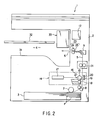
- FIG. 2 is a side view of the image forming apparatus schematically showing a positional relation of an image processing mechanism, conveyance passage, upper discharge tray and lower discharge tray in the first embodiment of the present invention.
- FIG. 3 is a perspective view of a separator unit according to the first embodiment of the present invention.
- FIG. 4 is a sectional view of the image forming apparatus showing that a gate is switched to a first changeover position in the first embodiment of the present invention.
- FIG. 5 is a sectional view of the image forming apparatus showing that the gate is switched to a second changeover position in the first embodiment of the present invention.
- FIG. 6 is a perspective view of a first roller group in a state in which an O ring is attached to a first attachment groove in the first embodiment of the present invention.
- FIG. 7 is a perspective view of a driving roller in a state in which the O ring is attached to a second attachment groove in the first embodiment of the present invention.
- FIG. 8 is a side view of the driving roller in the state in which the O ring is attached to the first attachment groove in the first embodiment of the present invention.
- FIG. 9 is a side view of the driving roller in the state in which the O ring is attached to the second attachment groove in the first embodiment of the present invention.
- FIG. 10 is a side view of the driving roller showing the first attachment groove in an enlarged manner according to the first embodiment of the present invention.
- FIG. 11 is a sectional view of the O ring for use in the first embodiment of the present invention.
- FIG. 12 is a sectional view taken along line F12-F12 of FIG. 9.
- FIG. 13 is a flowchart of a process for giving a wavy shape to a recording sheet in the first embodiment of the present invention.
- FIG. 14 is a sectional view of the image forming apparatus showing that the gate is switched to the first changeover position in a second embodiment of the present invention.
- FIG. 15 is a sectional view of the image forming apparatus showing that the gate is switched to the second changeover position in the second embodiment of the present invention.
- FIG. 16 is a perspective view showing a position relation between a roller unit and a pressing mechanism' in the second embodiment of the present invention.
- FIG. 17 is a flowchart showing a process for giving the wavy shape to the recording sheet in the second embodiment of the present invention.
- FIG. 18 is a perspective view showing a position relation of the gate, pressing mechanism and roller unit in a third embodiment of the present invention.
- FIG. 19 is a sectional view of the image forming apparatus showing that the gate is switched to the second changeover position in the third embodiment of the present invention.
- FIG. 20 is a sectional view of the image forming apparatus showing that the gate is switched to the first changeover position in the third embodiment of the present invention.
- A first embodiment of the present invention will be described hereinafter based on FIGS. 1 to 13.
- FIGS. 1 and 2 show an
image forming apparatus 1 such as a copying machine. Theimage forming apparatus 1 has a box-shapedapparatus body 2. Theapparatus body 2 has apaper feed cassette 3 andpaper discharge chamber 4. Thepaper feed cassette 3 is disposed in a bottom part of theapparatus body 2. Recording paper P is stored in thepaper feed cassette 3. Thepaper discharge chamber 4 is positioned in a middle part in the height direction of theapparatus body 2, and opened to the outside of theapparatus body 2. -
- A
conveyance passage 5 is formed inside theapparatus body 2. Through theconveyance passage 5, the recording paper P is conveyed to thepaper discharge chamber 4 from thepaper feed cassette 3. Theconveyance passage 5 extends in the height direction of theapparatus body 2. A downstream end of theconveyance passage 5 is connected to thepaper discharge chamber 4 via apaper discharge port 6 formed in theapparatus body 2. Thepaper discharge port 6 is positioned in the middle part in the height direction of thepaper discharge chamber 4. Thepaper discharge port 6 horizontally extends crossing at right angles to the conveyance direction of the recording paper P. - A
paper feed roller 7, a plurality ofconveyance rollers 8 andpaper discharge guide 9 are disposed in theconveyance passage 5. Thepaper feed roller 7 feeds out the recording paper P stored in thepaper feed cassette 3 sheet by sheet to theconveyance passage 5. Theconveyance rollers 8 are positioned on the downstream side from thepaper feed roller 7 along the conveyance direction of the recording paper P. Thepaper discharge guide 9 horizontally guides the recording paper P conveyed upwards along theconveyance passage 5. Thepaper discharge guide 9 is positioned in an upper end of theconveyance passage 5. - As shown in FIG. 4, a
photosensor 10 andactuator 11 are attached to thepaper discharge guide 9. The photosensor 10 optically detects the recording paper P conveyed to the vicinity of a downstream end of theconveyance passage 5. Thephotosensor 10 has a light emitting portion and light receiving portion (not shown). Theactuator 11 can be rotated to a standby position to advance into theconveyance passage 5, and a detection position to retreat from theconveyance passage 5. Theactuator 11 has an interceptor 11a which extends toward thephotosensor 10. The interceptor 11a retreats from between the light emitting portion and the light receiving portion as long as theactuator 11 is in the standby position. - When the recording paper P conveyed through the
conveyance passage 5 contacts theactuator 11 in the standby position, theactuator 11 is rotated to the detection position from the standby position. Thereby, the interceptor 11a advances between the light emitting portion and the light receiving portion of thephotosensor 10, and intercepts light. As a result, the photosensor 10 optically detects that the recording paper P reaches the downstream end of theconveyance passage 5, and sends a control signal to acontroller 12. - As shown in FIG. 2, the
apparatus body 2 contains animage processing mechanism 14. Theimage processing mechanism 14 forms an image on the recording paper P, and is positioned midway in theconveyance passage 5. Theimage processing mechanism 14 includes aphotosensitive drum 15, chargingapparatus 16, exposingapparatus 17, developingapparatus 18, transferringapparatus 19,destaticizing apparatus 20 and fixingapparatus 21. - As shown in FIGS. 2 to 4, a
roller unit 23 for discharging the sheet is disposed at the downstream end of theconveyance passage 5. Theroller unit 23 feeds the recording paper P having reached the downstream end of theconveyance passage 5 out to thepaper discharge port 6. Theroller unit 23 includes afirst roller group 24 and asecond roller group 25. Thefirst roller group 24 is constituted of aroller shaft 26 and a plurality of drivingrollers 27. Theroller shaft 26 is horizontally disposed along thepaper discharge part 6. Theroller shaft 26 is rotated by a drive source such as a motor (not shown). The drivingrollers 27 are supported by theroller shaft 26. These drivingrollers 27 are arranged at intervals in an axial direction of theroller shaft 26, and arranged in a row along a direction crossing at right angles to the conveyance direction of the recording paper P. - The
second roller group 25 is positioned under thefirst roller group 24. Thesecond roller group 25 is constituted of aroller shaft 28 and a plurality of drivenrollers 29. Theroller shaft 28 is horizontally disposed along thepaper discharge port 6. The drivenrollers 29 are supported by theroller shaft 28. These drivenrollers 29 are arranged at intervals in the axial direction of theroller shaft 28, and contact the drivingrollers 27 of thefirst roller group 24. Therefore, the first andsecond roller groups - As shown in FIGS. 2 and 4, the
paper discharge chamber 4 of theapparatus body 2 includes alower discharge tray 31 andupper discharge tray 32 as stackers. Thelower discharge tray 31 is integrally formed in the bottom of thepaper discharge chamber 4, and disposed in a position lower than that of thepaper discharge port 6. Theupper discharge tray 32 is detachably supported by theapparatus body 2. Theupper discharge tray 32 is disposed above thelower discharge tray 31, and in a position higher than that of thepaper discharge port 6. - Furthermore, a
separator unit 33 is disposed in the upper part of thepaper discharge chamber 4. Theseparator unit 33 is detachably supported in theapparatus body 2, and positioned above thepaper discharge port 6. As shown in FIGS. 4 and 5, theseparator unit 33 includes aconveyance guide 34. Theconveyance guide 34 is positioned between theupper discharge tray 32 and thepaper discharge port 6. Theconveyance guide 34 has aguide passage 35. Theguide passage 35 guides the recording paper P discharged from thepaper discharge port 6 to theupper discharge tray 32. Theguide passage 35 is constituted of first andsecond corner portions linear portion 36c. The first andsecond corner portions first corner portion 36a is positioned in the upstream end of theguide passage 35, and changes the discharge direction of the recording paper P discharged from thepaper discharge port 6 to an upward direction. Thesecond corner portion 36b is positioned in the downstream end of theguide passage 35, and changes the conveyance direction of the recording paper P conveyed upwards to a horizontal direction. Thelinear portion 36c extends over the first andsecond corner portions guide passage 35 is bent in a crank shape, and the downstream end thereof is disposed in a position higher than that of theupper discharge tray 32. - As shown in FIGS. 3 to 5, a
discharge roller unit 38 is disposed in the downstream end of theguide passage 35. Thedischarge roller unit 38 discharges the recording paper P onto theupper discharge tray 32. Thedischarge roller unit 38 includes afirst roller group 39 andsecond roller group 40. Thefirst roller group 39 is constituted of aroller shaft 41 and a plurality of drivingrollers 42. Theroller shaft 41 is supported by theseparator unit 33, and horizontally extends along the direction crossing at right angles to the conveyance direction of the recording paper P. Theroller shaft 41 is rotated by a driving source (not shown) such as a motor. The drivingrollers 42 are supported by theroller shaft 41. These drivingrollers 42 are disposed at intervals in the axial direction of theroller shaft 41. - The
second roller group 40 is positioned on thefirst roller group 39. Thesecond roller group 40 is constituted of aroller shaft 43 and a plurality of drivenrollers 44. Theroller shaft 43 is disposed in parallel to theroller shaft 41. The drivenrollers 44 are supported by theroller shaft 43. These drivenrollers 44 are disposed at intervals in the axial direction of theroller shaft 43, and contact the drivingrollers 42 of thefirst roller group 39. Therefore, the first andsecond roller groups - As shown in FIGS. 3 to 5, the
separator unit 33 includes achangeover mechanism 46 for changing the discharge direction of the recording paper P discharged from thepaper discharge port 6. Thechangeover mechanism 46 includes asupport shaft 47 and a plurality ofgates 48. Thesupport shaft 47 is supported by theseparator unit 33, and horizontally extends along the direction crossing at right angles to the conveyance direction of the recording paper P. Press levers 49a, 49b are fixed to opposite ends of thesupport shaft 47. The press levers 49a, 49b are disposed in parallel to each other via thesupport shaft 47. Thegates 48 are supported by thesupport shaft 47, and arranged at intervals in the axial direction of thesupport shaft 47. Thesegates 48 are positioned opposite thepaper discharge port 6 in the upstream end of theguide passage 35. Furthermore, thegates 48 haveedges 48a disposed opposite thefirst corner portion 36a of theguide passage 35. Theedges 48a are curved along thefirst corner portion 36a in the circular arc shape. Thegates 48 are rotated to either the first changeover position or the second changeover position. FIG. 4 shows that thegates 48 are rotated to the first changeover position. In the first changeover position, thegates 48 retreat in the position higher than that of thepaper discharge port 6, and theedges 48a are detached from thepaper discharge port 6. Therefore, the recording paper P discharged from thepaper discharge port 6 passes under thegates 48 and drops onto thelower discharge tray 31. - FIG. 5 shows that the
gates 48 are rotated to the second changeover position. In the second changeover position, thegates 48 jut out under theseparator unit 33, and theedges 48a are disposed opposite to thepaper discharge port 6. Therefore, the recording paper P discharged from thepaper discharge port 6 is guided by theedges 48a of thegates 48 and fed into theguide passage 35 of theseparator unit 33. - As well shown in FIG. 3, the
separator unit 33 includes a drivingdevice 50. The drivingdevice 50 moves thegates 48 to the second changeover position from the first changeover position or in reverse. The drivingdevice 50 includes an L-shapedlink 51 andsolenoid 52. - The L-shaped
link 51 has a middle portion as a fulcrum, and the middle portion is connected to one end of thesupport shaft 47. Thesolenoid 52 includes aplunger 53 which operates linearly. Theplunger 53 is connected to the L-shapedlink 51 via anarm 54. A connected portion of the L-shapedlink 51 andarm 54 is positioned under thesupport shaft 47. The L-shapedlink 51 is biased in a counterclockwise direction in FIG. 3 via a pair ofreturn springs 55a, 55b. One return spring 55a extends between the L-shapedlink 51 and theseparator unit 33. Theother return spring 55b extends between thepress lever 49b and theseparator unit 33. - When the
solenoid 52 is turned OFF, theplunger 53 projects. At this time, the L-shapedlink 51 is pulled in the counterclockwise direction centering on thesupport shaft 47 by the return spring 55a. Therefore, thesupport shaft 47 is rotated in the counterclockwise direction, and thegates 48 are moved to the first changeover position as shown by an arrow A of FIG. 4. - When the
solenoid 52 is turned ON, theplunger 53 is retired. Thereby, one end of the L-shapedlink 51 is pulled in a clockwise direction against the spring force of the return spring 55a. Then, thesupport shaft 47 rotates in the clockwise direction, and thegates 48 are moved to the second changeover position from the first changeover position, as shown by arrow B in FIG. 5. - As shown in FIGS. 3 to 5, the
separator unit 33 includes apress mechanism 60. Thepress mechanism 60 waves the recording paper P discharged from thepaper discharge port 6, and temporarily makes the recording paper P rigid. Thepress mechanism 60 is positioned between thegates 48 and thepaper discharge port 6. - The
press mechanism 60 includes afirst roller group 61 andsecond roller group 62. Thefirst roller group 61 includes aroller shaft 63, a plurality of drivenrollers 64 and a plurality ofpress rollers 65. Theroller shaft 63 is horizontally disposed along the direction crossing at right angles to the conveyance direction of the recording paper P. Theroller shaft 63 is supported by theseparator unit 33 via a pair oflinks 66a, 66b. Thelinks 66a, 66b are attached to opposite ends of theroller shaft 63. Theselinks 66a, 66b haverespective pivot shafts 67 apart from theroller shaft 63. Thepivot shafts 67 are rotatably supported by theseparator unit 33. Therefore, thelinks 66a, 66b can rotate centering on thepivot shafts 67, and are constantly biased downwards via springs (not shown). The drivenrollers 64 are supported by theroller shaft 63, and disposed at intervals in the axial direction of theroller shaft 63. Thepress rollers 65 are supported by theroller shaft 63, and positioned between the drivenrollers 64 disposed adjacent to each other. Therefore, the drivenrollers 64 andpress rollers 65 are alternately arranged in the direction crossing at right angles to the conveyance direction of the recording paper P. - Furthermore, the
press rollers 65 have diameters larger than those of the drivenrollers 64. Therefore, the outer peripheral surfaces of thepress rollers 65 extends outwards from the outer peripheral surfaces of the drivenrollers 64. - The
second roller group 62 is positioned under thefirst roller group 61. Thesecond roller group 62 includes aroller shaft 69, and a plurality of drivingrollers 70. Theroller shaft 69 is supported by theseparator unit 33, and disposed in parallel to theroller shaft 63 of thefirst roller group 61. Theroller shaft 69 receives the power from a motor (not shown) and rotates. The drivingrollers 70 are supported by theroller shaft 69. These drivingrollers 70 are disposed at intervals in the axial direction of theroller shaft 69, and contact the drivenrollers 64 of thefirst roller group 61 from below. Therefore, when the drivingrollers 70 rotate, the drivenrollers 64 andpress rollers 65 rotate accordingly. As a result, the recording paper P discharged from thepaper discharge port 6 is guided between the drivingrollers 70 and the drivenrollers 64, held between therollers paper discharge chamber 4. - The outer peripheral surfaces of the
press rollers 65 jut out downwards from the contact portions of the drivenrollers 64 and drivingrollers 70. Therefore, thepress rollers 65 are pressed onto a plurality of portions of the recording paper P. Thereby, a downward pressure is applied to the recording paper P, and a wavy shape is given to the recording paper P. - As shown in FIG. 3, the
links 66a, 66b supporting theroller shaft 63 are positioned under the press levers 49a, 49b. The ends of thelinks 66a, 66b opposite theroller shaft 63 are constantly pressed onto the press levers 49a, 49b by spring forces of the springs. When thegates 48 rotate toward the first changeover position shown in FIG. 4, the press levers 49a, 49b rotate in the counterclockwise direction of FIG. 3 via thesupport shaft 47. By the rotation, the contact portions of the press levers 49a, 49b andlinks 66a, 66b are moved to positions higher than the positions of thepivot shafts 67, and thelinks 66a, 66b rotate in the clockwise direction. As a result, thefirst roller group 61 moves to a press position in which thepress rollers 65 are pressed onto the recording paper P. Therefore, as long as thegates 48 are in the first changeover position, thepress rollers 65 wave the recording paper P discharged from thepaper discharge port 6. - When the
gates 48 rotate toward the second changeover position shown in FIG. 5, the press levers 49a, 49b rotate in the clockwise direction of FIG. 3 via thesupport shaft 47. By the rotation, the contact portions of the press levers 49a, 49b andlinks 66a, 66b move to the positions lower than the positions of thepivot shafts 67, and thelinks 66a, 66b rotate in the counterclockwise direction. As a result, thefirst roller group 61 moves to a press release position in which thepress rollers 65 are detached from the recording paper P. Therefore, as long as thegates 48 are in the second changeover position, thepress rollers 65 are not pressed onto the recording paper P. - Therefore, the
press rollers 65 follow the movement of thegates 48 and are moved to either the press position or the press release position. In the present embodiment, the press levers 49a, 49b andlinks 66a, 66b constitute cooperation means for transmitting the movement of thegates 48 to thepress rollers 65. - As shown in FIGS. 3 to 6, the
first roller group 39 of thedischarge roller unit 38 has a plurality ofpress rollers 72 as another press mechanism. Thepress rollers 72 are positioned in the downstream end of theguide passage 35. Thesepress rollers 72 are supported by theroller shaft 41, and positioned between the drivingrollers 42 disposed adjacent to each other. Therefore, the drivingrollers 42 andpress rollers 72 are alternately arranged in the direction crossing at right angles to the conveyance direction of the recording paper P. - Furthermore, the
press rollers 72 have diameters larger than those of the drivingrollers 42. The outer peripheral surfaces of thepress rollers 72 jut out from the outer peripheral surfaces of the drivingrollers 42. Therefore, when the recording paper P is discharged onto theupper discharge tray 32 from theguide passage 35, thepress rollers 72 are pressed onto the plurality of portions of the recording paper P from below. Thereby, an upward pressure is applied to the recording paper P, and a wavy shape is given to the recording paper P. - The
press mechanism 60 is attached to theseparator unit 33. Therefore, when theseparator unit 33 is detached from theapparatus body 2, the recording paper P discharged from thepaper discharge port 6 cannot be waved. As a countermeasure, in theimage forming apparatus 1 of the present embodiment, a mechanism for waving the recording paper P is added to theroller unit 23 positioned in the downstream end of theconveyance passage 5. - FIGS. 6 to 12 show details of the
first roller group 24 of theroller unit 23. Of the drivingrollers 27 of thefirst roller group 24, some specified ones haveportion 76 that extends in the axial direction. Theextended portions 76 are disconnected from the drivenrollers 29, and disposed opposite to theroller shaft 28 which supports the drivenrollers 29. -
First attachment grooves 77 and asecond attachment grooves 78 are formed in the outer peripheral surfaces of the drivingrollers 27. The first andsecond attachment grooves rollers 27, and are disposed apart from each other in the axial direction of the drivingrollers 27. Thefirst attachment grooves 77 are positioned in theextended portions 76 of the drivingrollers 27. Depth dimensions D1 of thefirst attachment grooves 77 are smaller than depth dimensions D2 of thesecond attachment grooves 78. O rings 80 as press members are attached to thefirst attachment groove 77 orsecond attachment groove 78. The O rings 80 are constituted of elastically deformable rubber materials. When the O rings 80 are in a free state, inner diameters of the O rings 80 are substantially equal to the diameters of the bottom portions of thesecond attachment grooves 78. Furthermore, linear diameters d of the O rings 80 are larger than the depth dimensions D1 of thefirst attachment grooves 77, and smaller than the depth dimensions D2 of thesecond attachment grooves 78. - The O rings 80 can selectively moved over a first position in which the rings are attached to the
first attachment grooves 77, and a second position in which the rings are attached to thesecond attachment grooves 78. FIGS. 6 and 8 show that the O rings 80 are attached to thefirst attachment grooves 77. In the first position, the O rings 80 jut out from the outer peripheral surfaces of the drivingrollers 27. Therefore, when the recording paper P passes between the drivingrollers 27 and the drivenrollers 29, the O rings 80 are pressed onto the plurality of portions of the recording paper P from above. Thereby, a downward pressure is applied to the recording paper P, and the wavy shape is given to the recording paper P. - FIGS. 7 and 9 show that the O rings 80 are attached to the
second attachment grooves 78. In the second position, the O rings 80 completely fit in thesecond attachment grooves 78, and retreat from the outer peripheral surfaces of the drivingrollers 27. Therefore, when the recording paper P passes between the drivingrollers 27 and the drivenrollers 29, the O rings 80 do not contact the recording paper P. Therefore, the recording paper P is discharged from thepaper discharge port 6 without being waved. - The driving
rollers 27 include ends 81 disposed on an opposite side of theextended portions 76. This ends 81 have a plurality ofcutouts 82. Thecutouts 82 are disposed at intervals in a peripheral direction of the drivingroller 27. Thecutouts 82 are opened in the outer peripheral surfaces of theends 81 of the drivingrollers 27, the end surfaces of theends 81 andsecond attachment grooves 78. As shown in FIG. 12, when the O rings 80 are attached to thesecond attachment grooves 78, the O rings 80 are exposed in the direction of the end surfaces of theends 81 through thecutouts 82. - Therefore, as shown in FIG. 9, when a
tool 83 such as a driver is inserted into thecutouts 82 from the end surface of theend 81, thetool 83 can be caught by theO ring 80 in thesecond attachment groove 78. Therefore, even when the O rings 80 completely fit in thesecond attachment grooves 78, the O rings 80 can easily be removed from thesecond attachment grooves 78. - According to the constitution of the driving
rollers 27, when the O rings 80 are attached to either thefirst attachment grooves 77 or thesecond attachment grooves 78, it can easily be selected whether or not to give the wavy shape to the recording paper P. Therefore, even when theseparator unit 33 having thepress mechanism 60 is detached from theapparatus body 2, the drivingrollers 27 of theroller unit 23 can be used to give the wavy shape to the recording paper P. As a result, the recording paper P dropping onto thelower discharge tray 31 from thepaper discharge port 6 temporarily becomes rigid, and the recording paper P is stacked onto thelower discharge tray 31 in an orderly aligned state. - An operation of the
image forming apparatus 1 with theseparator unit 33 attached to thepaper discharge chamber 4 of theapparatus body 2 will next be described. When the recording paper P with the image formed thereon is guided to theupper discharge tray 32, the recording paper P is guided into theguide passage 35 without being pressed by thepress rollers 65. When the recording paper P with the image formed thereon is guided onto thelower discharge tray 31, the recording paper P is pressed by thepress rollers 65. - A procedure for pressing or not pressing the recording paper P will be described with reference to a flowchart shown in FIG. 13.
- First it is selected in step S1 whether or not to give the wavy shape to the recording paper P. When the recording paper P is guided onto the
upper discharge tray 32, the recording paper P does not have to be waved, and therefore the procedure shifts to step S2. In the step S2, thesolenoid 52 is on standby by a command from thecontroller 12. - In the next step S3, the recording paper P conveyed through the
conveyance passage 5 is detected. When the tip end of the recording paper P contacts theactuator 11 of thepaper discharge guide 9, theactuator 11 rotates to the detection position from the standby position. By the rotation, the photosensor 10 optically detects that the recording paper P reaches the downstream end of theconveyance passage 5, and sends the control signal to thecontroller 12. - In the next step S4, the
solenoid 52 is turned ON by the command from thecontroller 12. Thereby, theplunger 53 of thesolenoid 52 is retired, and the L-shapedlink 51 rotates against the spring force of the return spring 55a in the clockwise direction. As a result, thegates 48 are moved to the second changeover position from the first changeover position. The movement of thegates 48 is transmitted to thefirst roller group 61 of thepress mechanism 60 via the press levers 49a, 49b andlinks 66a, 66b. Therefore, thefirst roller group 61 moves to the press release position, and thepress rollers 65 and drivenrollers 64 are detached from the drivingrollers 70. - As a result, as shown in FIG. 5, the tip end of the recording paper P discharged from the
paper discharge port 6 passes between thefirst roller group 61 and thesecond roller group 62, and thepress rollers 65 and drivenrollers 64 do not contact the recording paper P. Therefore, the recording paper P is not given the wavy shape. - In the next step S5, it is detected whether or not the rear end of the recording paper P conveyed through the
conveyance passage 5 passes through thepaper discharge guide 9. When the recording paper P passes through thepaper discharge guide 9, theactuator 11 returns to the standby position from the detection position. Therefore, thephotosensor 10 sends the control signal indicating the passage of the recording paper P to thecontroller 12. When theactuator 11 is held in the detection position, thecontroller 12 judges that there is a problem in the conveyance of the recording paper P, and the procedure advances to step S6. In the step S6, an error is displayed in a display (not shown) of theimage forming apparatus 1, indicating that the problem has arisen in the conveyance of the recording paper P. - When the passage of the recording paper P through the
paper discharge guide 9 is detected in the step S5, the procedure advances to step S7. In the step S7, thecontroller 12 counts constant pulses. Thereby, a required standby time is measured from when the rear end of the recording paper P passes through thepaper discharge guide 9 until the paper passes through thedischarge roller unit 38. - In the next step S8, the
solenoid 52 is turned OFF by the command from thecontroller 12. Therefore, thegates 48 are moved to the first changeover position from the second changeover position, and thefirst roller group 61 of thepress mechanism 60 follows the movement of thegates 48 and moves to the press position from the press release position. Thereby, the conveyance of one recording sheet P is completed. - In the step S4, as shown in FIG. 5, the recording paper P passed between the
first roller group 61 and thesecond roller group 62 is guided by theedges 48a of thegates 48, and the conveyance direction is changed to the upward direction from the horizontal direction. Furthermore, the recording paper P is conveyed to thesecond corner portion 36b through thelinear portion 36c from thefirst corner portion 36a of theconveyance passage 35. Therefore, when the recording paper P is passed through theconveyance passage 5, the conveyance direction is again changed to the horizontal direction from the upward direction. - The recording paper P having reached the downstream end of the
guide passage 35 is discharged onto theupper discharge tray 31 by thedischarge roller unit 38. Thefirst roller group 39 of thedischarge roller unit 38 has a plurality ofpress rollers 72. Therefore, when the recording paper P reaches the downstream end of theguide passage 35, thepress rollers 72 are pressed onto the plurality of portions of the recording paper P from below. Thereby, the upward pressure is applied to the recording paper P, and the wavy shape is given to the recording paper P. Therefore, the recording paper P temporarily becomes rigid, and is stacked onto theupper discharge tray 32 in the orderly aligned state. - When the recording paper P is guided onto the
lower discharge tray 31, the recording paper P needs to be waved, and therefore the procedure shifts to step S9 from the step S1. In the step S9, thesolenoid 52 is kept OFF. Therefore, as shown in FIG. 4, thegates 48 are held in the first changeover position, and thefirst roller group 61 of thepress mechanism 60 is held in the press position. As a result, thepress rollers 65 are pressed onto the plurality of portions of the recording paper P discharged from thepaper discharge port 6 from above. Thereby, the downward pressure is applied to the recording paper P, and the wavy shape is given to the recording paper P. Therefore, the recording paper P temporarily becomes rigid, and is stacked onto thelower discharge tray 31 in the orderly aligned state. - According to the
image forming apparatus 1, when the recording paper P is guided into theguide passage 35 bent in the crank shape, thefirst roller group 61 of thepress mechanism 60 is held in the press release position. Therefore, the recording paper P is not waved. When the recording paper P passes through theguide passage 35, an unnecessary force is not applied to the recording paper P. Therefore, the recording paper P can be prevented from abnormally sounding as if something were broken. - Furthermore, since the recording paper P is smoothly conveyed in the
guide passage 35, the recording paper P is not wrinkled, and jamming does not occur. - FIGS. 14 to 17 show a second embodiment of the present invention. The second embodiment is different from the first embodiment in a constitution of a
press mechanism 90 for giving the wavy shape to the recording paper P. The basic constitution of theimage forming apparatus 1 excluding thepress mechanism 90 is similar to that of the first embodiment. Therefore, in the second embodiment, the same constituting components as those of the first embodiment are denoted with the same reference numerals, and the description thereof is omitted. - As shown in FIGS. 14 to 16, the
press mechanism 90 is supported by theapparatus body 2. Thepress mechanism 90 is positioned in the downstream end of theconveyance passage 5, and disposed adjacent to the dischargingroller unit 23. Thepress mechanism 90 has aguide shaft 91 and a plurality ofpress members 92. Theguide shaft 91 is positioned under thesecond roller group 25 of theroller unit 23, and disposed in parallel to theroller shaft 28 of thesecond roller group 25. The opposite ends of theroller shaft 91 are supported byframes 94 viabearings 93, respectively. Theframes 94 are fixed to theapparatus body 2. - The
press members 92 are fixed to theguide shaft 91, and arranged at intervals in the axial direction of theguide shaft 91. Thesepress members 92 are positioned between the drivenrollers 29 on theroller shaft 28. As shown in FIGS. 14 and 15, thepress members 92 project along the diametric direction of theguide shaft 91, and have press surfaces 95 on the projecting tip end thereof. The press surfaces 95 are curved in the circular arc shapes. - The
press members 92 can rotate over the press release position and press position. FIG. 15 shows that thepress members 92 are rotated to the press release position. In the press release position, thepress members 92 are inclined toward the upstream side along the conveyance direction of the recording paper P with respect to thesecond roller group 25. Therefore, the press surfaces 95 of thepress members 92 retreat below theconveyance passage 5. - FIG. 14 shows that the
press members 92 are rotated to the press position. In the press position, thepress members 92 are allowed to rise just before the drivenrollers 29, and the press surfaces 95 of thepress members 92 jut out in theconveyance passage 5. The press surfaces 95 deviate toward the upstream side along the conveyance direction of the recording paper P from the contact portions of the drivenrollers 29 and recording paper P. Therefore, the press surfaces 95 are pressed onto the recording paper P from below before the recording paper P is guided between the drivingrollers 27 and the drivenrollers 29. Thereby, the upward pressure is applied to the recording paper P, and the wavy shape is given to the recording paper P. - As shown in FIG. 16, the
press mechanism 90 includes a drivingdevice 97. The drivingdevice 97 moves thepress members 92 to the press position from the position release position or in reverse. The drivingdevice 97 includes asolenoid 98 and L-shapedlink 99. Thesolenoid 98 is supported by theframe 94 via abracket 100. Thesolenoid 98 includes aplunger 101 which operates linearly. Theplunger 101 is connected to one end of the L-shapedlink 99. The other end of the L-shapedlink 99 is connected to one end of theguide shaft 91. Therefore, the L-shapedlink 99 rotates centering on the other end. Furthermore, the L-shapedlink 99 is biased in the counterclockwise direction of FIG. 16 via areturn spring 102. - When the
solenoid 98 is OFF, theplunger 101 projects. At this time, the L-shapedlink 99 is pulled in the counterclockwise direction centering on theguide shaft 91 via thereturn spring 102. Therefore, theguide shaft 91 rotates in the counterclockwise direction, and thepress members 92 are held in the press position as shown in FIG. 14. - When the
solenoid 98 is ON, theplunger 101 is retired. Thereby, the L-shapedlink 99 is pulled in the clockwise direction against the spring force of thereturn spring 102. Then, theguide shaft 91 rotates in the clockwise direction, and thepress members 92 are moved to the press release position from the press position as shown in FIG. 15. - FIG. 17 is a flowchart showing a procedure for waving the recording paper P and discharging the paper from the
paper discharge port 6, or discharging the recording paper P from thepaper discharge port 6 without waving the paper. As shown in FIG. 17, first it is selected in step S1 whether or not to give the wavy shape to the recording paper P. When the recording paper P is guided onto theupper discharge tray 32, the recording paper P does not have to be waved, and therefore the procedure shifts to step S2. - In the step S2, the
gates 48 are moved to the second changeover position from the first changeover position. Moreover, upon receiving the command from thecontroller 12, thesolenoid 98 is on standby. In the next step S3, the recording paper P conveyed through theconveyance passage 5 is detected. When the tip end of the recording paper P contacts theactuator 11 of thepaper discharge guide 9, theactuator 11 rotates to the detection position from the standby position. By this rotation, the photosensor 10 optically detects that the recording paper P reaches the downstream end of theconveyance passage 5, and sends the control signal to thecontroller 12. - In the next step S4, upon receiving the command from the
controller 12, thesolenoid 98 turns ON. Thereby, theplunger 101 of thesolenoid 98 is retired, and the L-shapedlink 99 rotates against the spring force of thereturn spring 102 in the clockwise direction. Thereby, theguide shaft 91 rotates in the clockwise direction, and thepress members 92 on theguide shaft 91 are moved to the press release position from the press position as shown in FIG. 15. Thereby, the recording paper P is guided into theroller unit 23 without contacting the press surfaces 95, and discharged from thepaper discharge port 6 via theroller unit 23. Therefore, the wavy shape is not given to the recording paper P. The tip end of the recording paper P is guided into theguide passage 35 by theedges 48a of thegates 48. - In the next step S5, it is detected whether or not the rear end of the recording paper P conveyed through the
conveyance passage 5 passes through thepaper discharge guide 9. When the recording paper P passes through thepaper discharge guide 9, theactuator 11 returns to the standby position from the detection position. Therefore, thephotosensor 10 sends the control signal indicating the passage of the recording paper P to thecontroller 12. When theactuator 11 is held in the detection position, thecontroller 12 judges that there is a problem in the conveyance of the recording paper P, and the procedure advances to step S6. In the step S6, the error is displayed in the display (not shown) of theimage forming apparatus 1, indicating that the problem has arisen in the conveyance of the recording paper P. - When the passage of the recording paper P through the
paper discharge guide 9 is detected in the step S5, the procedure advances to step S7. In the step S7, thecontroller 12 counts the constant pulses. Thereby, the required standby time is measured from when the rear end of the recording paper P passes through thepaper discharge guide 9 until the paper passes through thedischarge roller unit 38. - In the next step S8, the
solenoid 98 is turned OFF by the command from thecontroller 12. Therefore, thepress members 92 return to the press position from the press release position. Moreover, thegates 48 are moved to the first changeover position from the second changeover position. Thereby, the conveyance of one recording sheet P is completed. - When the recording paper P is guided onto the
lower discharge tray 31, the recording paper P needs to be waved, and therefore the procedure shifts to step S9 from the step S1. In the step S9, thesolenoid 98 keeps OFF state, and thegates 48 are held in the first changeover position. Therefore, as shown in FIG. 14, thepress members 92 are held in the press position, and the press surfaces 95 jut out in theconveyance passage 5. As a result, the press surfaces 95 are pressed onto the plurality of portions of the recording paper P passed through thepaper discharge guide 9 from below. Thereby, the upward pressure is applied to the recording paper P, and the wavy shape is given to the recording paper P. Therefore, the recording paper P temporarily becomes rigid, and is stacked onto thelower discharge tray 31 in the orderly aligned state. - According to the constitution, when the recording paper P is guided into the
guide passage 35 bent in a crank shape, the recording paper P is not waved. Therefore, when the recording paper P passes through theguide passage 35, the unnecessary force is not applied to the recording paper P. Therefore, the recording paper P can be prevented from abnormally sounding as if something were broken. - Furthermore, the press surfaces 95 of the
press members 92 press the recording paper P in the position deviating toward the upstream side along the conveyance direction of the recording paper P from the drivenrollers 29. Therefore, the recording paper P is smoothly conveyed in the downstream end of theconveyance passage 5. In other words, if the press surfaces 95 are positioned on the downstream side from the drivenrollers 29 along the conveyance direction of the recording paper P, the recording paper P discharged from theroller unit 23 rides onto the press surfaces 95. Therefore, the smooth conveyance of the recording paper P is inhibited, and the jamming is caused. - Therefore, the
press members 92 are preferably disposed in the position deviating toward the upstream side from the contact portions of the recording paper P and drivenrollers 29. - FIGS. 18 to 20 show a third embodiment of the present invention. The third embodiment is different from the first embodiment in the constitution of a
press mechanism 110 for giving the wavy shape to the recording paper P. The basic constitution of theimage forming apparatus 1 excluding thepress mechanism 110 is similar to that of the first embodiment. Therefore, in the third embodiment, the same constituting components as those of the first embodiment are denoted with the same reference numerals, and the description thereof is omitted. - As shown in FIG. 18, the
press mechanism 110 includes aguide frame 111 and a plurality ofpress members 112. Theguide frame 111 is positioned below theroller unit 23, and disposed in parallel to theroller shaft 28 of thesecond roller group 25. Thepress members 112 are fixed to theguide frame 111. Thesepress members 112 are disposed at intervals in the longitudinal direction of theguide frame 111. A press surfaces 113 are formed on the upper ends of thepress members 112. The press surfaces 113 are positioned between the drivenrollers 29 disposed adjacent to each other. - A
gate 115 for changing the discharge direction of the recording paper P is horizontally disposed along the direction crossing at right angles to the conveyance direction of the recording paper P. Thegate 115 includes a pair ofsupport shafts 116a, 116b, a pair of guide pins 117a, 117b and aguide surface 118 for guiding the recording paper P upwards. - The support shaft 116a projects from one end of the
gate 115. Thesupport shaft 116b projects from the other end of thegate 115. Thesupport shafts 116a, 116b are coaxially disposed, and are arranged in parallel to theroller shaft 28. Thesesupport shafts 116a, 116b are rotatably supported by theseparator unit 33. The support shaft 116a is connected to theplunger 53 of thesolenoid 52 via the L-shapedlink 51 andarm 54. Therefore, thegate 115 can rotate over the first and second changeover positions by thesolenoid 52. Thegate 115 is constantly biased toward the first changeover position by thereturn spring 55. This respect is the same as the first embodiment. - The guide pin 117a projects from one end of the
gate 115, and is disposed in parallel to the support shaft 116a. The guide pin 117b projects from the other end of thegate 115, and is disposed in parallel to thesupport shaft 116b. These guide pins 117a, 117b deviate from thesupport shafts 116a, 116b toward thepaper discharge port 6. - The
separator unit 33 has alink mechanism 120. Thelink mechanism 120 connects thegate 115 to thepress mechanism 110. Thelink mechanism 120 includes a pair offirst links 121 and a pair ofsecond links 122. Thefirst links 121 are disposed opposite to each other via thegate 115. Thefirst links 121 have first guide holes 123, second guide holes 124 and cam surfaces 125. The first guide holes 123 horizontally extend along the discharge direction of the recording paper P. The second guide holes 124 extend in the vertical direction crossing at right angles to the discharge direction of the recording paper P, and are curved in the circular arc shapes. The cam surfaces 125 are positioned in the tip ends of thefirst links 121. The cam surfaces 125 are inclined downwards. - The
first links 121 are disposed between a pair ofside plates 126a, 126b. Theside plates 126a, 126b are fixed to theseparator unit 33. Theside plates 126a, 126b haveguide pins 128 projecting toward thefirst links 121. The guide pins 128 are slidably inserted in the first guide holes 123 of thefirst links 121. Furthermore, the guide pins 117a, 117b of thegate 115 are slidably inserted in the second guide holes 124 of thefirst links 121. Therefore, thefirst links 121 can horizontally move along the discharge direction of the recording paper P, and can rotate on the guide pins 128 as the fulcrum. - The
second links 122 are disposed below the drivenrollers 29 of theroller unit 23. Thesecond links 122 are fixed to theguide frame 111 of thepress mechanism 110, and are disposed opposite to each other via thepress members 112. Eachsecond link 122 has aguide hole 130. The guide holes 130 extend in the vertical direction. Guide pins 131 horizontally project from the upper end of theguide hole 130, and are disposed in parallel to thesupport shafts 116a, 116b of thegate 115. - The
second links 122 are disposed between a pair offrames 132. Theframes 132 are disposed opposite to each other via thepress mechanism 110, and fixed to theseparator unit 33. Each of theframes 132 has two guide pins 133. The guide pins 133 horizontally project toward thesecond links 122, and are slidably inserted in the guide holes 130 of thesecond links 122. Therefore, thesecond links 122 are supported in theframes 132 so that the links can rise/lower. Thereby, thepress members 112 of thepress mechanism 110 can move over the press position in which the press surfaces 113 jut out in theconveyance passage 5 and the press release position in which the press surfaces 113 retreats downwards in theconveyance passage 5. The guide pins 131 of thesecond links 122 are superposed upon the cam surfaces 125 of thefirst links 121. - An operation of the
press mechanism 110 will next be described. FIG. 19 shows that thegate 115 is rotated to the second changeover position. When thegate 115 is rotated toward the second changeover position, the guide pins 117a, 117b on the tip end of thegate 115 move downwards along the second guide holes 124 of thefirst links 121. Thereby, thefirst links 121 are guided by the guide pins 128 and slide apart from thesecond links 122. Additionally, thefirst links 121 slightly rotate on the guide pins 128 as the fulcrum in the clockwise direction of FIG. 19. - As a result, the cam surfaces 125 of the
first links 121 move apart from the guide pins 131 of thesecond links 122. Therefore, the guide pins 131 lower along the cam surfaces 125, and thesecond links 122 move downwards. Thereby, thepress mechanism 110 moves to the press release position apart from theroller unit 23. In the press release position, the press surfaces 113 of thepress members 112 retreat from theconveyance passage 5. Therefore, as long as thegate 115 is in the second changeover position, the press surfaces 113 are not pressed onto the recording paper P. - FIG. 20 shows that the
gate 115 is rotated to the first changeover position. When thegate 115 is rotated toward the first changeover position, the guide pins 117a, 117b on the tip end of thegate 115 rises along the second guide holes 124 of thefirst links 121. Thereby, thefirst links 121 are guided by the guide pins 128 and slide close to thesecond links 122. Additionally, thefirst links 121 slightly rotate on the guide pins 128 as the fulcrum in the counterclockwise direction of FIG. 20. - As a result, the cam surfaces 125 of the
first links 121 move close to the guide pins 131 of thesecond links 122. Therefore, the guide pins 131 are pushed up by the cam surfaces 125, and thesecond links 122 move upwards. Thereby, thepress mechanism 110 moves to the press position right under theroller unit 23. In the press position, the press surfaces 113 of thepress members 112 jut out in theconveyance passage 5, and are pressed onto the plurality of portions of the recording paper P from below. Therefore, as long as thegate 115 is in the first changeover position, thepress surface 113 give the wavy shape to the recording paper P guided by theroller unit 23. - According to the constitution, when the recording paper P is guided into the
guide passage 35 bent in the crank shape, thegate 115 is held in the second changeover position, and therefore the recording paper P is not waved. Therefore, when the recording paper P passes through theguide passage 35, the unnecessary force is not applied to the recording paper P. The recording paper P can be prevented from abnormally sounding as if something were broken. - In the present invention, the means for driving the gate is not limited to the solenoid. For example, a motor including a decelerator may also be used instead of a solenoid.
Claims (23)
- A sheet discharge apparatus comprising:characterized in that:a conveyance passage (5) to convey a sheet (P);a plurality of stackers (31, 32) on which the sheet (P) discharged from said conveyance passage (5) is stacked;a gate (48, 115) which changes a discharge direction of the sheet (P) discharged from said conveyance passage (5), said gate (48, 115) being able to move over a first changeover position to guide said sheet (P) to said one stacker (31), and a second changeover position to guide said sheet (P) to said other stacker (32);a guide passage (35) which guides said sheet (P) to said other stacker (32), when said gate (48, 115) is moved to the second changeover position, said guide passage (35) having a bent shape; andpressing means (60, 90, 110) disposed on the upstream side from said gate (48, 115) along a conveyance direction of the sheet (P),said pressing means (60, 90, 110) applying a pressure and giving a wavy shape to the sheet (P), and temporarily makes the sheet (P) rigid, when said gate (48, 115) is moved to the first changeover position.
- The sheet discharge apparatus according to claim 1, characterized by further comprising:another pressing means (72) disposed in a downstream end of said guide passage (35), said pressing means (72) applying a pressure and giving a wavy shape to said sheet (P) discharged to said other stacker (32) from said guide passage (35), and temporarily making the sheet (P) rigid.
- The sheet discharge apparatus according to claim 1, characterized in that said one stacker (31) is in a position lower than a downstream end of said conveyance passage (5), said other stacker (32) is in a position higher than the downstream end of said conveyance passage (5), and said guide passage (35) extends upwards from the downstream end of said conveyance passage (5), and has a plurality of corner portions (36a, 36b) midway in the guide passage (35).
- The sheet discharge apparatus according to claim 1, characterized in that said conveyance passage (5) has a pair of roller groups (24, 25) which hold and convey said sheet (P) in the downstream end of the conveyance passage (5), said pressing means (90) has a press surface (95) pressed onto said sheet (P), and the press surface (95) gives the wavy shape to said sheet (P) in a position deviating toward the upstream side along the conveyance direction of said sheet (P) from a contact portion of said roller groups (24, 25) and said sheet (P).
- The sheet discharge apparatus according to claim 1, characterized in that said conveyance passage (5) has a roller unit (23) which discharges said sheet (P) in a downstream end of the conveyance passage (5), said pressing means (60) includes a pair of roller groups (61, 62) which hold said sheet (P), and a plurality of press rollers (65) disposed coaxially with one roller group (61) and pressed onto said sheet (P), and the pressing means (60) is positioned between said roller unit (23) and said gate (48).
- The sheet discharge apparatus according to claim 1, characterized in that said pressing means (60, 90, 110) can move over a press position in which the pressing means is pressed onto said sheet (P) and a press release position in which the pressing means is detached from said sheet (P), and the pressing means (60, 90, 110) is held in said press position as long as said gate (48, 115) is moved to said first changeover position; and is held in said press release position as long as said gate (48, 115) is held in the second changeover position.
- The sheet discharge apparatus according to claim 6, characterized by further comprising:a driving device (50) which moves said gate (48) to said second changeover position from said first changeover position and in reverse; and cooperation means (49a, 49b, 66a, 66b) for transmitting the movement of said gate (48) to said pressing means (60).
- A sheet discharge apparatus comprising:characterized in that:a conveyance passage (5) to convey a sheet (P);at least a roller (27) disposed in a downstream end of said conveyance passage (5), said roller (27) having an outer peripheral surface in contact with said sheet (P);a plurality of stackers (31, 32) on which the sheet (P) discharged from said conveyance passage (5) is stacked;a gate (48, 115) which changes a discharge direction of the sheet (P) discharged from said conveyance passage (5), said gate (48, 115) being able to move over a first changeover position to guide said sheet (P) to said one stacker (31), and a second changeover position to guide said sheet (P) to said other stacker (32); anda guide passage (35) which guides said sheet (P) to said other stacker (32), when said gate (48, 115) is moved to the second changeover position, said guide passage (35) having a bent shape,said roller (27) has an annular pressing member (80) in the outer peripheral surface of the roller, and said pressing member (80) can selectively move to either a first position to jut out from the outer peripheral surface of said roller (27) or a second position to retreat from the outer peripheral surface of said roller (27), and applies a pressure and gives a wavy shape to said sheet (P), and temporarily makes the sheet (P) rigid, when the pressing member (80) is moved to said first position.
- The sheet discharge apparatus according to claim 8, characterized in that said pressing member (80) is an elastically deformable O ring (80), said roller (27) has a first attachment groove (77) and a second attachment groove (78) to which said O ring (80) is selectively and detachably attached in the outer peripheral surface of the roller (27), said second attachment groove (78) is formed to be deeper than the first attachment groove (77), the O ring (80) is held in said second position as long as the O ring (80) is attached to the second attachment groove (78), and the O ring (80) is held in said first position as long as the O ring (80) is attached to said first attachment groove (77).
- The sheet discharge apparatus according to claim 9, characterized in that said roller (27) has an end surface connected to the outer peripheral surface of the roller (27), and a plurality of cutouts (82) opened in the outer peripheral surface and the end surface, and the cutouts (82) are disposed at intervals in a peripheral direction of said roller (27), and connected to said second attachment groove (78).
- An image forming apparatus comprising:characterized in that:an apparatus body (2) in which an image processing mechanism (14) is disposed to form an image on a sheet (P);a conveyance passage (5) which is disposed in said apparatus body (2), and through which the sheet (P) with the image formed thereon is conveyed;a plurality of stackers (31, 32) on which the sheet (P) discharged from said conveyance passage (5) is stacked;a gate (48, 115) which changes a discharge direction of the sheet (P) discharged from said conveyance passage (5), said gate (48, 115) being able to move over a first changeover position to guide said sheet (P) to said one stacker (31), and a second changeover position to guide said sheet (P) to said other stacker (32);a guide passage (35) which guides said sheet (P) to said other stacker (32), when said gate (48, 115) is moved to the second changeover position, said guide passage (35) having a bent shape; andpressing means (60, 90, 110) disposed on the upstream side from said gate (48, 115) along a conveyance direction of the sheet (P),said pressing means (60, 90, 110) applying a pressure and giving a wavy shape to the sheet (P), and temporarily makes the sheet (P) rigid, when said gate (48, 115) is moved to the first changeover position.
- The image forming apparatus according to claim 11, characterized by further comprising:another pressing means (72) disposed in a downstream end of said guide passage (35), said pressing means (72) applying a pressure and giving a wavy shape to said sheet (P) discharged to said other stacker (32) from said guide passage (35), and temporarily making the sheet (P) rigid.
- The image forming apparatus according to claim 11, characterized by further comprising:a separator unit (33) detachably supported by said apparatus body (2), the separator unit (33) including said guide passage (35) and said gate (48, 115).
- The image forming apparatus according to claim 13, characterized in that said pressing means (60, 110) is supported by said separator unit (33).
- The image forming apparatus according to claim 13, characterized in that said pressing means (90) is supported by said apparatus body (2), and the pressing means (90) applies the pressure and gives the wavy shape to said sheet (P), and temporarily makes the sheet (P) rigid, when said separator unit (33) is detached from said apparatus body (2).
- The image forming apparatus according to claim 11, characterized in that said one stacker (31) is in a position lower than a downstream end of said conveyance passage (5), said other stacker (32) is in a position higher than the downstream end of said conveyance passage (5), and said guide passage (35) extends upwards from the downstream end of said conveyance passage (5), and has a plurality of corner portions (36a, 36b) midway in the guide passage (35).
- The image forming apparatus according to claim 11, characterized in that said apparatus body (2) has a paper discharge chamber (4) therein, and said stackers (31, 32) are disposed in said paper discharge chamber (4).
- The image forming apparatus according to claim 11, characterized in that said pressing means (60, 90, 110) can move over a press position in which the pressing means is pressed onto said sheet (P) and a press release position in which the pressing means is detached from said sheet (P), and the pressing means (60, 90, 110) is held in said press position as long as said gate (48, 115) is moved to said first changeover position, and is held in said press release position as long as said gate (48, 115) is held in the second changeover position.
- The image forming apparatus according to claim 18, characterized by further comprising:a driving device (50) which moves said gate (48) to said second changeover position from said first changeover position and in reverse; and cooperation means (49a, 49b, 66a, 66b) for transmitting the movement of said gate (48) to said pressing means (60).
- An image forming apparatus comprising:characterized in that:an apparatus body (2) in which an image processing mechanism (14) is disposed to form an image on a sheet (P);a conveyance passage (5) which is disposed in said apparatus body (2), and through which the sheet (P) with the image formed thereon is conveyed;first and second stackers (31, 32) which are disposed in said apparatus body (2), and on which the sheet (P) discharged from said conveyance passage (5) is stacked; anda separator unit (33) detachably supported by said apparatus body (2), and the separator unit (33) includes: a guide passage (35) which connects said second stacker (32) to a downstream end of said conveyance passage (5) and has a bent shape; and a gate (48,115) which can move over a first changeover position to guide the sheet (P) discharged from said conveyance passage (5) to said first stacker (31), and a second changeover position to guide the sheet (P) discharged from said conveyance passage (5) to said second stacker (32) via said guide passage (35),said separator unit (33) has pressing means (60, 110), and the pressing means (60, 110) applies a pressure and gives a wavy shape to the sheet (P) discharged from said conveyance passage (5), and temporarily makes the sheet (P) rigid, when said gate (48, 115) is moved to the first changeover position.
- The image forming apparatus according to claim 20, characterized in that said first stacker (31) is in a position lower than a downstream end of said conveyance passage (5), said second stacker (32) and said separator unit (33) are in a position higher than the downstream end of said conveyance passage (5), and said guide passage (35) of said separator unit (33) extends upwards from the downstream end of said conveyance passage (5), and has a plurality of corner portions (36a, 36b) midway in the guide passage (35).
- The image forming apparatus according to claim 21, characterized in that said separator unit (33) includes another pressing means (72) in the downstream end of the guide passage (35), and the pressing means (72) applies the pressure and gives the wavy shape to the sheet (P) discharged to said second stacker (32) from said guide passage (35), and temporarily makes the sheet (P) rigid.
- The image forming apparatus according to claim 20, characterized in that said conveyance passage (5) has a roller unit (23) which discharges said sheet (P) in a downstream end of the conveyance passage (5), said pressing means (60) includes a pair of roller groups (61, 62) which hold said sheet (P), and a plurality of press rollers (65) disposed coaxially with one roller group (61) and pressed onto said sheet (P), and the pressing means (60) is positioned between said roller unit (23) and said gate (48).
Applications Claiming Priority (4)
| Application Number | Priority Date | Filing Date | Title |
|---|---|---|---|
| JP2001081209 | 2001-03-21 | ||
| JP2001081209 | 2001-03-21 | ||
| JP2002060850A JP2002348027A (en) | 2001-03-21 | 2002-03-06 | Sheet ejecting device, and image forming device having the sheet ejecting device |
| JP2002060850 | 2002-03-06 |
Publications (3)
| Publication Number | Publication Date |
|---|---|
| EP1243541A2 true EP1243541A2 (en) | 2002-09-25 |
| EP1243541A3 EP1243541A3 (en) | 2004-01-14 |
| EP1243541B1 EP1243541B1 (en) | 2007-11-14 |
Family
ID=26611705
Family Applications (1)
| Application Number | Title | Priority Date | Filing Date |
|---|---|---|---|
| EP02006554A Expired - Lifetime EP1243541B1 (en) | 2001-03-21 | 2002-03-20 | Sheet discharge apparatus including pressing member for giving wavy shape to sheet and image forming apparatus including the same |
Country Status (4)
| Country | Link |
|---|---|
| US (2) | US6776408B2 (en) |
| EP (1) | EP1243541B1 (en) |
| JP (1) | JP2002348027A (en) |
| DE (1) | DE60223438T2 (en) |
Cited By (2)
| Publication number | Priority date | Publication date | Assignee | Title |
|---|---|---|---|---|
| CN102020140A (en) * | 2009-09-09 | 2011-04-20 | 三星电子株式会社 | Print-medium post-treatment apparatus |
| US8056898B2 (en) | 2003-11-07 | 2011-11-15 | Goss International Americas, Inc. | Pin conveyor for printed sheet material and transfer unit |
Families Citing this family (23)
| Publication number | Priority date | Publication date | Assignee | Title |
|---|---|---|---|---|
| US7216866B2 (en) * | 2003-04-28 | 2007-05-15 | Kyocera Mita Corporation | Sheet transport path switching mechanism |
| JP4145773B2 (en) * | 2003-11-06 | 2008-09-03 | パイオニア株式会社 | Information recording / reproducing apparatus and recording medium |
| EP1588972B1 (en) * | 2004-04-19 | 2013-02-27 | Canon Finetech Inc. | Sheet treating apparatus and image forming apparatus provided therewith |
| US7757972B2 (en) * | 2004-06-03 | 2010-07-20 | Illinois Tool Works Inc. | Conversion adapter for a fluid supply assembly |
| JP4474219B2 (en) * | 2004-07-15 | 2010-06-02 | 株式会社東芝 | Image forming apparatus and paper discharge method for image forming apparatus |
| JP4415911B2 (en) * | 2005-07-25 | 2010-02-17 | 富士ゼロックス株式会社 | Paper discharge device and image forming apparatus |
| JP2007325609A (en) * | 2006-06-06 | 2007-12-20 | Pentax Corp | Waterproof cap of ultrasonic signal connector of ultrasonic endoscope |
| JP4569907B2 (en) * | 2006-08-25 | 2010-10-27 | 株式会社沖データ | Medium conveying apparatus and image forming apparatus |
| JP4417940B2 (en) * | 2006-09-29 | 2010-02-17 | 株式会社沖データ | Image forming apparatus |
| JP4784941B2 (en) * | 2007-03-13 | 2011-10-05 | 株式会社リコー | Conveying device, image forming apparatus |
| US7762552B2 (en) * | 2007-10-26 | 2010-07-27 | Lexmark International, Inc. | Movable gate with fluid damper for directing media sheets within an image forming apparatus |
| JP5045376B2 (en) * | 2007-11-07 | 2012-10-10 | 富士ゼロックス株式会社 | Discharging device and image forming apparatus |
| KR101249842B1 (en) * | 2008-01-18 | 2013-04-03 | 삼성전자주식회사 | Image forming apparatus and method for controlling the same |
| JP5034973B2 (en) * | 2008-01-18 | 2012-09-26 | 富士ゼロックス株式会社 | Image forming apparatus |
| JP4889805B2 (en) * | 2010-08-06 | 2012-03-07 | シャープ株式会社 | Sheet conveying apparatus and image forming apparatus having the same |
| JP5605140B2 (en) * | 2010-09-30 | 2014-10-15 | 株式会社リコー | Image forming apparatus |
| JP2012106837A (en) * | 2010-11-17 | 2012-06-07 | Konica Minolta Business Technologies Inc | Paper carrying system and image forming system |
| JP2016124657A (en) * | 2014-12-26 | 2016-07-11 | 株式会社リコー | Recording sheet conveyance device and image formation apparatus using the same |
| JP6380188B2 (en) * | 2015-03-25 | 2018-08-29 | ブラザー工業株式会社 | Image forming apparatus |
| EP3429860B1 (en) * | 2016-06-29 | 2021-01-20 | Hewlett-Packard Development Company, L.P. | Media diversion apparatus |
| JP6953951B2 (en) * | 2017-05-31 | 2021-10-27 | セイコーエプソン株式会社 | Recording device |
| JP7069901B2 (en) * | 2018-03-19 | 2022-05-18 | セイコーエプソン株式会社 | Processing equipment |
| JP2022125833A (en) * | 2021-02-17 | 2022-08-29 | 富士フイルムビジネスイノベーション株式会社 | Post-processing device |
Citations (4)
| Publication number | Priority date | Publication date | Assignee | Title |
|---|---|---|---|---|
| US3087724A (en) * | 1960-09-15 | 1963-04-30 | Cummins Chicago Corp | Document delivery and stacking apparatus |
| EP0611719A1 (en) * | 1993-02-15 | 1994-08-24 | Riso Kagaku Corporation | Paper ejection device for a stencil printing device |
| JPH08157125A (en) * | 1994-12-01 | 1996-06-18 | Canon Inc | Sheet discharging device and image forming device |
| JPH09301590A (en) * | 1996-05-10 | 1997-11-25 | Canon Inc | Sheet material discharging device and image forming device |
Family Cites Families (3)
| Publication number | Priority date | Publication date | Assignee | Title |
|---|---|---|---|---|
| US5201518A (en) * | 1990-03-24 | 1993-04-13 | Canon Kabushiki Kaisha | Sheet transport mechanism having flapper |
| JP3245829B2 (en) | 1992-10-14 | 2002-01-15 | 株式会社リコー | Paper output straightening mechanism |
| US6181908B1 (en) * | 1999-09-10 | 2001-01-30 | Lexmark International, Inc. | Apparatus for corrugating materials |
-
2002
- 2002-03-06 JP JP2002060850A patent/JP2002348027A/en active Pending
- 2002-03-19 US US10/102,099 patent/US6776408B2/en not_active Expired - Lifetime
- 2002-03-20 DE DE60223438T patent/DE60223438T2/en not_active Expired - Lifetime
- 2002-03-20 EP EP02006554A patent/EP1243541B1/en not_active Expired - Lifetime
-
2004
- 2004-07-12 US US10/890,315 patent/US7040615B2/en not_active Expired - Lifetime
Patent Citations (4)
| Publication number | Priority date | Publication date | Assignee | Title |
|---|---|---|---|---|
| US3087724A (en) * | 1960-09-15 | 1963-04-30 | Cummins Chicago Corp | Document delivery and stacking apparatus |
| EP0611719A1 (en) * | 1993-02-15 | 1994-08-24 | Riso Kagaku Corporation | Paper ejection device for a stencil printing device |
| JPH08157125A (en) * | 1994-12-01 | 1996-06-18 | Canon Inc | Sheet discharging device and image forming device |
| JPH09301590A (en) * | 1996-05-10 | 1997-11-25 | Canon Inc | Sheet material discharging device and image forming device |
Non-Patent Citations (2)
| Title |
|---|
| PATENT ABSTRACTS OF JAPAN vol. 1996, no. 10, 31 October 1996 (1996-10-31) & JP 08 157125 A (CANON INC), 18 June 1996 (1996-06-18) * |
| PATENT ABSTRACTS OF JAPAN vol. 1998, no. 03, 27 February 1998 (1998-02-27) & JP 09 301590 A (CANON INC), 25 November 1997 (1997-11-25) * |
Cited By (3)
| Publication number | Priority date | Publication date | Assignee | Title |
|---|---|---|---|---|
| US8056898B2 (en) | 2003-11-07 | 2011-11-15 | Goss International Americas, Inc. | Pin conveyor for printed sheet material and transfer unit |
| CN102020140A (en) * | 2009-09-09 | 2011-04-20 | 三星电子株式会社 | Print-medium post-treatment apparatus |
| CN102020140B (en) * | 2009-09-09 | 2015-06-10 | 三星电子株式会社 | Print-medium post-treatment apparatus |
Also Published As
| Publication number | Publication date |
|---|---|
| US6776408B2 (en) | 2004-08-17 |
| US20020135124A1 (en) | 2002-09-26 |
| DE60223438T2 (en) | 2008-09-18 |
| JP2002348027A (en) | 2002-12-04 |
| EP1243541B1 (en) | 2007-11-14 |
| EP1243541A3 (en) | 2004-01-14 |
| DE60223438D1 (en) | 2007-12-27 |
| US20040251621A1 (en) | 2004-12-16 |
| US7040615B2 (en) | 2006-05-09 |
Similar Documents
| Publication | Publication Date | Title |
|---|---|---|
| EP1243541B1 (en) | Sheet discharge apparatus including pressing member for giving wavy shape to sheet and image forming apparatus including the same | |
| US6561503B1 (en) | Sheet processing device with stack alignment | |
| JP4224468B2 (en) | Sheet post-processing apparatus and image forming apparatus using the same | |
| US7503559B2 (en) | Sheet feeding device and image forming device with linked rotatable guide members and guide plate | |
| CN110320766B (en) | Image reading apparatus | |
| JP4316519B2 (en) | Sheet post-processing apparatus and image forming apparatus using the same | |
| CN110329829B (en) | Image reading apparatus | |
| US7883079B2 (en) | Sheet processing apparatus | |
| JP2014084191A (en) | Sheet storage device | |
| EP1898270B1 (en) | Sheet stacking apparatus and image forming apparatus | |
| US20050127598A1 (en) | Sheet convey apparatus | |
| US8794622B2 (en) | Sheet stacking device and image forming apparatus | |
| JP2014152012A (en) | Sheet post-processing device and image formation device | |
| US8534666B2 (en) | Sheet stacking apparatus and image forming apparatus | |
| US10554834B2 (en) | Image reading apparatus including movable plate and discharge unit | |
| EP1055623B1 (en) | Sheet feeder with lateral adjusting means | |
| CN104924778A (en) | Conveyor | |
| EP0449120A1 (en) | Sheet transport mechanism | |
| JP5441112B2 (en) | Sheet processing device | |
| JP4769736B2 (en) | Sheet processing apparatus and image forming apparatus | |
| JP2022059150A (en) | Recording material processing device and image formation system | |
| JP2014214016A (en) | Sheet storage device, and post-processor and image forming system using the same | |
| JP5350089B2 (en) | Printer | |
| JPH03192075A (en) | Recording paper transporting device for image recording device | |
| JP2006276557A (en) | Jam processing apparatus |
Legal Events
| Date | Code | Title | Description |
|---|---|---|---|
| PUAI | Public reference made under article 153(3) epc to a published international application that has entered the european phase |
Free format text: ORIGINAL CODE: 0009012 |
|
| 17P | Request for examination filed |
Effective date: 20020320 |
|
| AK | Designated contracting states |
Kind code of ref document: A2 Designated state(s): AT BE CH CY DE DK ES FI FR GB GR IE IT LI LU MC NL PT SE TR |
|
| AX | Request for extension of the european patent |
Free format text: AL;LT;LV;MK;RO;SI |
|
| PUAL | Search report despatched |
Free format text: ORIGINAL CODE: 0009013 |
|
| AK | Designated contracting states |
Kind code of ref document: A3 Designated state(s): AT BE CH CY DE DK ES FI FR GB GR IE IT LI LU MC NL PT SE TR |
|
| AX | Request for extension of the european patent |
Extension state: AL LT LV MK RO SI |
|
| AKX | Designation fees paid |
Designated state(s): DE FR GB |
|
| 17Q | First examination report despatched |
Effective date: 20050511 |
|
| GRAP | Despatch of communication of intention to grant a patent |
Free format text: ORIGINAL CODE: EPIDOSNIGR1 |
|
| GRAS | Grant fee paid |
Free format text: ORIGINAL CODE: EPIDOSNIGR3 |
|
| GRAA | (expected) grant |
Free format text: ORIGINAL CODE: 0009210 |
|
| AK | Designated contracting states |
Kind code of ref document: B1 Designated state(s): DE FR GB |
|
| REG | Reference to a national code |
Ref country code: GB Ref legal event code: FG4D |
|
| REF | Corresponds to: |
Ref document number: 60223438 Country of ref document: DE Date of ref document: 20071227 Kind code of ref document: P |
|
| ET | Fr: translation filed | ||
| PLBE | No opposition filed within time limit |
Free format text: ORIGINAL CODE: 0009261 |
|
| STAA | Information on the status of an ep patent application or granted ep patent |
Free format text: STATUS: NO OPPOSITION FILED WITHIN TIME LIMIT |
|
| 26N | No opposition filed |
Effective date: 20080815 |
|
| PGFP | Annual fee paid to national office [announced via postgrant information from national office to epo] |
Ref country code: DE Payment date: 20120411 Year of fee payment: 11 |
|
| REG | Reference to a national code |
Ref country code: DE Ref legal event code: R119 Ref document number: 60223438 Country of ref document: DE Effective date: 20131001 |
|
| PG25 | Lapsed in a contracting state [announced via postgrant information from national office to epo] |
Ref country code: DE Free format text: LAPSE BECAUSE OF NON-PAYMENT OF DUE FEES Effective date: 20131001 |
|
| REG | Reference to a national code |
Ref country code: FR Ref legal event code: PLFP Year of fee payment: 15 |
|
| REG | Reference to a national code |
Ref country code: FR Ref legal event code: PLFP Year of fee payment: 16 |
|
| REG | Reference to a national code |
Ref country code: FR Ref legal event code: PLFP Year of fee payment: 17 |
|
| PGFP | Annual fee paid to national office [announced via postgrant information from national office to epo] |
Ref country code: FR Payment date: 20210210 Year of fee payment: 20 |
|
| PGFP | Annual fee paid to national office [announced via postgrant information from national office to epo] |
Ref country code: GB Payment date: 20210310 Year of fee payment: 20 |
|
| REG | Reference to a national code |
Ref country code: GB Ref legal event code: PE20 Expiry date: 20220319 |
|
| PG25 | Lapsed in a contracting state [announced via postgrant information from national office to epo] |
Ref country code: GB Free format text: LAPSE BECAUSE OF EXPIRATION OF PROTECTION Effective date: 20220319 |