EP1243474A2 - Load compartment cover for vehicles, in particular for station wagons and the like - Google Patents
Load compartment cover for vehicles, in particular for station wagons and the like Download PDFInfo
- Publication number
- EP1243474A2 EP1243474A2 EP02005703A EP02005703A EP1243474A2 EP 1243474 A2 EP1243474 A2 EP 1243474A2 EP 02005703 A EP02005703 A EP 02005703A EP 02005703 A EP02005703 A EP 02005703A EP 1243474 A2 EP1243474 A2 EP 1243474A2
- Authority
- EP
- European Patent Office
- Prior art keywords
- cover according
- guide
- loading space
- roller blind
- drive wheel
- Prior art date
- Legal status (The legal status is an assumption and is not a legal conclusion. Google has not performed a legal analysis and makes no representation as to the accuracy of the status listed.)
- Granted
Links
Images


Classifications
-
- B—PERFORMING OPERATIONS; TRANSPORTING
- B60—VEHICLES IN GENERAL
- B60R—VEHICLES, VEHICLE FITTINGS, OR VEHICLE PARTS, NOT OTHERWISE PROVIDED FOR
- B60R5/00—Compartments within vehicle body primarily intended or sufficiently spacious for trunks, suit-cases, or the like
- B60R5/04—Compartments within vehicle body primarily intended or sufficiently spacious for trunks, suit-cases, or the like arranged at rear of vehicle
- B60R5/044—Compartments within vehicle body primarily intended or sufficiently spacious for trunks, suit-cases, or the like arranged at rear of vehicle luggage covering means, e.g. parcel shelves
- B60R5/045—Compartments within vehicle body primarily intended or sufficiently spacious for trunks, suit-cases, or the like arranged at rear of vehicle luggage covering means, e.g. parcel shelves collapsible or transformable
- B60R5/047—Compartments within vehicle body primarily intended or sufficiently spacious for trunks, suit-cases, or the like arranged at rear of vehicle luggage covering means, e.g. parcel shelves collapsible or transformable collapsible by rolling-up
-
- Y—GENERAL TAGGING OF NEW TECHNOLOGICAL DEVELOPMENTS; GENERAL TAGGING OF CROSS-SECTIONAL TECHNOLOGIES SPANNING OVER SEVERAL SECTIONS OF THE IPC; TECHNICAL SUBJECTS COVERED BY FORMER USPC CROSS-REFERENCE ART COLLECTIONS [XRACs] AND DIGESTS
- Y10—TECHNICAL SUBJECTS COVERED BY FORMER USPC
- Y10S—TECHNICAL SUBJECTS COVERED BY FORMER USPC CROSS-REFERENCE ART COLLECTIONS [XRACs] AND DIGESTS
- Y10S160/00—Flexible or portable closure, partition, or panel
- Y10S160/02—Auto screens and miscellaneous
Definitions
- the invention relates to a luggage compartment cover for motor vehicles, such as Combined passenger cars or the like, according to claim 1.
- such a loading space cover is included one arranged in a roller blind housing, by means of a spring motor in the winding direction driven winding shaft for receiving a material web described.
- the inner transverse edge of the material web is on the winding shaft attached, while the outer transverse edge of a simultaneously designed as an end board Cross stiffening is held.
- the roller blind housing of the two longitudinal guides attached to the vehicle Independently attached in the vehicle mounting area.
- From DE 42 00 021 A1 is a loading space cover with a Cover roller blind known, in which the roller blind housing including material web and cross stiffening assigned to the two longitudinal guides releasably attached are:
- DE 40 16 707 A1 describes a loading space cover designed as a folding cover known, in which both-sided heads of cross struts each arranged in undercut C-shaped longitudinal guides are.
- Each of the two longitudinal guides takes a sufficiently pressure-resistant Perforated tape made of plastic.
- For translational drive of the two perforated tapes grip their inner ends at diametrically opposite Circumferential locations of a drive wheel provided with approximately spike-like extensions form-fitting.
- the two longitudinal guides with the perforated bands as well as the one receiving the drive wheel with an electric drive motor Overall, the drive unit forms a coherent rigid vehicle-fixed installed assembly.
- the invention has for its object a simple Handling load compartment cover of compact design with motorized To create drive.
- the blind housing including the Material web and its transverse stiffening releasable the two longitudinal guides attached assigned.
- the roller blind housing according to the invention at least one motor drive for two elongated, deflectable, Sufficiently rigid transmission medium sections (e.g. perforated tapes).
- This Gear means sections each engage with their outer end Guide element (e.g. on a sliding block) of the cross bracing and can in and out of the roller blind housing into the assigned longitudinal guide be moved out of this again.
- the invention accordingly provides a cargo space cover the roller blind housing with the material web wound on the winding shaft together with the cross bracing away from the longitudinal guides Vehicle removed and again, so to speak, with a grip in his Attachment position can be traced.
- each gear means section is located in positive engagement with a drive wheel.
- Each drive wheel are guide areas for the corresponding one Gearbox section assigned, of which a rectilinear guide area ensures that the assigned gear means section is aligned Way is introduced into the longitudinal guide.
- Another leadership area the part-circular guide area surrounds a partial circumference of the drive wheel and thus ensures a precise, positive engagement between the Gear means section and the drive wheel.
- a deflection guide area is arranged on the side of the drive wheel, which especially for an unobstructed entry movement of the respective interior End of the gear means sections ensures while the fabric is wound up becomes.
- Recording rooms are also connected to the redirection guide areas or a common receiving space for the inner ends of the Gear means sections.
- These receiving spaces formed by the roller blind housing or the common receiving space for the inner ends of both Gear means sections form, just like the feature that the blind housing accommodates both the transmission means and the motor drive, a special peculiarity of the invention and are also an essential requirement for the compact design achieved by the invention.
- the winding shaft is expediently driven in the winding direction in a known manner with a spring motor assigned to the winding shaft, which is stretched when extending or unwinding the material web, and which relaxes when the material web is wound up.
- a spring motor assigned to the winding shaft, which is stretched when extending or unwinding the material web, and which relaxes when the material web is wound up.
- each drive motor is an electric drive motor, in particular is a reversible electric drive motor.
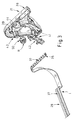
- the load compartment cover 10 has a roller blind housing 11, which of Can be used above in receiving pockets 13 of fixed receptacles 12 on the vehicle side is.
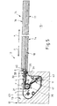
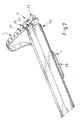
- the guide rails 14 each consist of an upper rail 16 and a lower one Sub-rail 17 together and so enclose a C-shaped undercut Guide channel 18 (see. Fig. 5), the inner longitudinal side of each to the cargo space 15 is open.
- the roller blind housing 11 has a central housing part 19 and on the latter both ends of the drive housing 20, each by means of an end cap 21 are closed.
- the drive housing 20 with end caps 21 can if necessary along the longitudinal axis z inwards to the middle Housing part 19 can be designed to be spring-loaded, if this is the mounting assembly in the vehicle-side fixtures 12 required.
- a hollow winding shaft 23 is received, whose interior contains a spring motor, not shown, in a known manner, which tries to turn the winding shaft 23 in the winding direction u.
- the Unwinding direction is denoted by v.
- Each drive housing 20 carries an electric drive motor M. a flanged gearbox G. Both gears G are by means of a two Synchronous shaft 24 having subshafts 25 are rotatably connected to one another. Both mutually facing ends of the partial shafts 25 are by means of one Length compensation permitting connector 26 rotatably coupled.
- the drive wheels R like the winding shaft 23, are in the end caps 21 pivoted.
- a flexible or pliable material web W is with its inner Cross edge attached to the winding shaft 23 in a manner not shown.
- a hollow profile Tension rod (cross stiffening) 30 attached, which in turn an end board 31st holds.
- a plug insert 32 is located in each end of the tension rod 30 (see FIGS. 6 and 7) of a sliding block S (guide element).
- the sliding block S indicates Upper part 33 and a lower part 34, which, both screwed together, the outer end 35 of the perforated tape L form-fit tensile and pressure resistant between to record oneself.
- the lower part 34 has projections 36, which the Pass through holes 37 of perforated tape L. Incidentally, in the drawings the holes 37 of the perforated tapes L are only partially entered.
- each forms End cap 21 between the drive wheel R and the adjacent guide channel 18 a rectilinear guide projection aligned with the guide channel 18 38
- the guide channel 18 has on his the rectilinear guide projection 38 has a funnel-shaped end Widening 40 on.
- part circle guide area 39 which the Drive wheel R surrounds part-circle and for a precise positive engagement and pressure between perforated tape L and drive wheel R.
- a deflection guide area closes on the inside of the pitch circle guide area 39 41, which is designed like a channel and by means of a Channel plate 42 is closed and which the perforated tape L - in its Direction of movement viewed from top to bottom - with a bend towards leads below and at the same time twists about the longitudinal axis of the perforated tape L.
- the perforated strip L can be parallel to the material web W and parallel to the longitudinal axis z of the roller blind housing 11 in the housing longitudinal channel 27 thereof (common receiving space for the inner ends 28 of the perforated tape L) be filed.
- the rotary bearing receptacles formed by or associated with the end caps 21 for the winding shaft 23 are a total of 43 and the respective Rotary bearing mount for the drive wheel designated 44.
- FIG. 8 shows how each drive for the perforated belt L is designed is.
- the roughly cylindrical drive wheel R has short strip-like circumferences Provide projections 50 which are in the correspondingly shaped Holes 37 of the perforated tape L can engage.
- a stub shaft 45 provides the rotary connection between the drive wheel R and a universal joint 46, which in turn has a stub shaft 47 is rotatably connected to the gearbox G.
- the plug connection required for this is designed similar to that provided with a square plug receptacle 48 Output shaft 49, which (see FIG. 2) each as a rotary mount for a partial shaft 25 of the synchronous shaft 24 is used.
- the cargo hold cover 10 functions as follows (see FIG. 5):
- the roller blind housing 11 arranged in the receptacles 12 contains the wound one Material web W (see FIG. 2).
- the electrical contact pairs K1 (contact-side or vehicle-side contact pair) and K2 (contact pair the roller blind housing 11) the electrical feed to the two reversible electric drive motors M.
- the feed can initially be switched so that the Turn drive wheels R in the unwinding direction of rotation v so that the one with Perforated tape L motion-coupled sliding block S in the direction of extension x of the material web W first in the funnel-shaped expansion 40 and then in the Guide channel 18 moved into it itself.
- a return movement of the sliding block S in the direction of retraction y the material web W is carried out in an analogous reverse manner by means of a corresponding Reversing the electrical feed.
- the electrical control can be conveniently by remote control or also by means of appropriate switches, e.g. also coupled with the tailgate can be semi-automatic or fully automatic.
- the respective end position shutdown with respect to the two directions of movement x and y can expediently be formed by means of the inner ends 28 of the perforated bands L, which are provided with switching cams can be, which cooperate with the electrical microswitches on the side of the roller blind housing.
Abstract
Description
Die Erfindung betrifft eine Laderaumabdeckung für Kraftwagen, wie für Kombinations-Personenkraftwagen od. dgl., entsprechend dem Anspruch 1.The invention relates to a luggage compartment cover for motor vehicles, such as Combined passenger cars or the like, according to claim 1.
In der älteren DE 100 38 842 A1 ist eine solche Laderaumabdeckung mit einer in einem Rollogehäuse angeordneten, mittels eines Federmotors im Aufwickeldrehsinn angetriebenen Wickelwelle zur Aufnahme einer Werkstoffbahn beschrieben. Der innere Querrand der Werkstoffbahn ist an der Wickelwelle befestigt, während deren äußerer Querrand an einer zugleich als Endbord ausgebildeten Querversteifung gehalten ist. Dem Endbord ist beidendig je ein Führungselement (Gleitstein) zugeordnet, welches jeweils in einer fahrzeugseitig befestigten Längsführung (Führungsschiene) gleitbar angeordnet ist, die einen U-förmigen oder hinterschnittenen C-förmigen Querschnitt aufweisen kann. Auf diese Weise ist die Werkstoffbahn mittels ihres an den Führungs-Gleitelementen geführten Endbordes in Schließ- und Öffnungsrichtung geführt. Schließlich ist das Rollogehäuse von den beiden fahrzeugseitig befestigten Längsführungen unabhängig im fahrzeugseitigen Einbaufeld befestigt.In the older DE 100 38 842 A1, such a loading space cover is included one arranged in a roller blind housing, by means of a spring motor in the winding direction driven winding shaft for receiving a material web described. The inner transverse edge of the material web is on the winding shaft attached, while the outer transverse edge of a simultaneously designed as an end board Cross stiffening is held. There is a guide element on both ends of the end board (Sliding block) assigned, each in a vehicle side attached longitudinal guide (guide rail) is slidably arranged, the one Can have a U-shaped or undercut C-shaped cross section. On in this way the material web is attached to the guide sliding elements guided outboard in the closing and opening direction. Finally is the roller blind housing of the two longitudinal guides attached to the vehicle Independently attached in the vehicle mounting area.
Von der DE 42 00 021 A1 ist eine Laderaumabdeckung mit einem Abdeckrollo bekannt, bei welcher das Rollogehäuse einschließlich Werkstoffbahn und Querversteifung den beiden Längsführungen lösbar befestigt zugeordnet sind:From DE 42 00 021 A1 is a loading space cover with a Cover roller blind known, in which the roller blind housing including material web and cross stiffening assigned to the two longitudinal guides releasably attached are:
In der DE 198 25 353 A1 ist eine Laderaumabdeckung insbesondere für Kombinations-Kraftwagen beschrieben, welche an beiden Längsseiten des Laderaums je einen mit einem eigenen Antriebsmotor versehenen Linearantrieb aufweist, welcher mit Mitnehmern zur lösbaren Kupplung mit einer am freien Querrand angeordneten Querversteifung einer Rollobahn versehen ist. Beide elektrische Antriebsmotoren sind mittels einer Synchronisierungsvorrichtung im Gleichlaufsinne drehzahlgeregelt.DE 198 25 353 A1 describes a loading space cover, in particular for Combination motor vehicles described, which on both long sides of the Each have a linear drive with its own drive motor has, which with drivers for releasable coupling with one at the free Transverse stiffening of a blind sheet is provided. Both electric drive motors are by means of a synchronization device in the Speed-controlled synchronous sense.
Von der DE 40 16 707 A1 ist eine als Faltabdeckung ausgebildete Laderaumabdeckung bekannt, bei welcher beidendseitige Köpfe von Querstreben jeweils in hinterschnittenen C-förmig profilierten Längsführungen angeordnet sind. Jede der beiden Längsführungen nimmt ein hinreichend drucksteifes Lochband aus Kunststoff auf. Zum translatorischen Antrieb der beiden Lochbänder greifen deren innere Enden an diametral gegenüberliegenden Umfangsstellen eines mit etwa stachelartigen Fortsätzen versehenen Antriebsrades formschlüssig an. Die beiden Längsführungen mit den Lochbändern sowie die das Antriebsrad mit einem elektrischen Antriebsmotor aufnehmende Antriebseinheit bilden insgesamt eine zusammenhängende starre fahrzeugfest installierte Baugruppe.DE 40 16 707 A1 describes a loading space cover designed as a folding cover known, in which both-sided heads of cross struts each arranged in undercut C-shaped longitudinal guides are. Each of the two longitudinal guides takes a sufficiently pressure-resistant Perforated tape made of plastic. For translational drive of the two perforated tapes grip their inner ends at diametrically opposite Circumferential locations of a drive wheel provided with approximately spike-like extensions form-fitting. The two longitudinal guides with the perforated bands as well as the one receiving the drive wheel with an electric drive motor Overall, the drive unit forms a coherent rigid vehicle-fixed installed assembly.
Ausgehend von der in der älteren DE 100 38 842 A1 beschriebenen Laderaumabdeckung, liegt der Erfindung die Aufgabe zugrunde, eine einfach zu handhabende Laderaumabdeckung kompakter Bauform mit motorischem Antrieb zu schaffen.Starting from the one described in the older DE 100 38 842 A1 Load compartment cover, the invention has for its object a simple Handling load compartment cover of compact design with motorized To create drive.
Diese Aufgabe wird entsprechend der Gesamtheit der Merkmale des Anspruchs 1 gelöst.This task is carried out according to the entirety of the characteristics of the Claim 1 solved.
Entsprechend der Erfindung sind das Rollogehäuse einschließlich der Werkstoffbahn und deren Querversteifung den beiden Längsführungen lösbar befestigt zugeordnet. Zugleich enthält das erfindungsgemäße Rollogehäuse mindestens einen motorischen Antrieb für zwei langgestreckte, umlenkbare, hinreichend drucksteife Getriebemittel-Abschnitte (z. B. Lochbänder). Diese Getriebemittel-Abschnitte greifen jeweils mit ihrem äußeren Ende an einem Führungselement (z.B. an einem Gleitstein) der Querversteifung an und können aus dem Rollogehäuse heraus in die zugeordnete Längsführung hinein- und aus dieser wieder herausbewegt werden. According to the invention, the blind housing including the Material web and its transverse stiffening releasable the two longitudinal guides attached assigned. At the same time contains the roller blind housing according to the invention at least one motor drive for two elongated, deflectable, Sufficiently rigid transmission medium sections (e.g. perforated tapes). This Gear means sections each engage with their outer end Guide element (e.g. on a sliding block) of the cross bracing and can in and out of the roller blind housing into the assigned longitudinal guide be moved out of this again.
Mit der Erfindung ist demnach eine Laderaumabdeckung geschaffen worden, deren Rollogehäuse bei auf der Wickelwelle aufgewickelter Werkstoffbahn mitsamt der Querversteifung von den Längsführungen weg aus dem Fahrzeug entnommen und wiederum gewissermaßen mit einem Griff in seine Befestigungslage zurückgeführt werden kann.The invention accordingly provides a cargo space cover the roller blind housing with the material web wound on the winding shaft together with the cross bracing away from the longitudinal guides Vehicle removed and again, so to speak, with a grip in his Attachment position can be traced.
Sobald sich das Rollogehäuse in der Befestigungslage befindet und die Energieeinspeisung des motorischen Antriebs hergestellt ist, kann letzterer in Gang gesetzt und die Getriebemittel-Abschnitte mitsamt der mit der Werkstoffbahn verbundenen Querversteifung ausgefahren und bei Bedarf wiederum eingefahren werden.As soon as the blind housing is in the fastening position and the Energy supply of the motor drive is made, the latter in Gear set and the transmission medium sections together with that with the material web connected cross stiffener extended and retracted if necessary become.
In weiterer Ausgestaltung der Erfindung befindet sich jeder Getriebemittel-Abschnitt im getrieblichen Formschlusseingriff mit einem Antriebsrad.In a further embodiment of the invention, each gear means section is located in positive engagement with a drive wheel.
Jedem Antriebsrad sind Führungsbereiche für den korrespondierenden Getriebemittel-Abschnitt zugeordnet, von denen ein geradliniger Führungsbereich dafür sorgt, dass der zugeordnete Getriebemittel-Abschnitt in ausgerichteter Weise in die Längsführung eingeführt wird. Ein anderer Führungsbereich, der teilkreisförmige Führungsbereich, umgibt einen Teilumfang des Antriebsrades und sorgt so für einen präzisen formschlüssigen Eingriff zwischen dem Getriebemittel-Abschnitt und dem Antriebsrad.Each drive wheel are guide areas for the corresponding one Gearbox section assigned, of which a rectilinear guide area ensures that the assigned gear means section is aligned Way is introduced into the longitudinal guide. Another leadership area the part-circular guide area surrounds a partial circumference of the drive wheel and thus ensures a precise, positive engagement between the Gear means section and the drive wheel.
Schließlich ist an der dem geradlinigen Führungsbereich abgewandten Seite des Antriebsrades ein Umlenkungs-Führungsbereich angeordnet, welcher insbesondere für eine behinderungsfreie Einfahrbewegung des jeweiligen inneren Endes der Getriebemittel-Abschnitte sorgt, während die Stoffbahn aufgewickelt wird.Finally, on the straight-ahead guide area A deflection guide area is arranged on the side of the drive wheel, which especially for an unobstructed entry movement of the respective interior End of the gear means sections ensures while the fabric is wound up becomes.
An die Umlenkungs-Führungsbereiche schließen sich außerdem Aufnahmeräume oder ein gemeinsamer Aufnahmeraum für die inneren Enden der Getriebemittel-Abschnitte an. Diese vom Rollogehäuse gebildeten Aufnahmeräume oder der gemeinsame Aufnahmeraum für die inneren Enden beider Getriebemittel-Abschnitte bilden, ebenso wie das Merkmal, das das Rollogehäuse sowohl die Getriebemittel als auch den motorischen Antrieb aufnimmt, eine besondere Eigenart der Erfindung und sind zudem eine wesentliche Voraussetzung für die von der Erfindung erzielte kompakte Bauform.Recording rooms are also connected to the redirection guide areas or a common receiving space for the inner ends of the Gear means sections. These receiving spaces formed by the roller blind housing or the common receiving space for the inner ends of both Gear means sections form, just like the feature that the blind housing accommodates both the transmission means and the motor drive, a special peculiarity of the invention and are also an essential requirement for the compact design achieved by the invention.
Der Antrieb der Wickelwelle im Aufwickeldrehsinn geschieht zweckmäßig in bekannter Weise mit einem der Wickelwelle zugeordneten Federmotor, welcher beim Ausfahren bzw. Abwickeln der Werkstoffbahn gespannt wird, und welcher sich beim Aufwickeln der Werkstoffbahn entspannt. Zur Unterstützung der Aufwickelbewegung kann es zweckmäßig sein, einen reversierbaren Antriebsmotor zu verwenden, welcher sowohl beim Ausfahren als auch beim Aufwickeln (Einfahren) der Werkstoffbahn tätig ist.The winding shaft is expediently driven in the winding direction in a known manner with a spring motor assigned to the winding shaft, which is stretched when extending or unwinding the material web, and which relaxes when the material web is wound up. For support the winding movement, it may be useful to have a reversible To use drive motor, which both when extending and when Winding (retracting) the material web is active.
Überhaupt hat es sich neben anderen Antriebsarten als zweckmäßig herausgestellt, dass jeder Antriebsmotor ein elektrischer Antriebsmotor, insbesondere ein reversierbarer elektrischer Antriebsmotor ist.In general, in addition to other types of drives, it has proven to be useful that each drive motor is an electric drive motor, in particular is a reversible electric drive motor.
Ebenfalls der einfachen Handhabung und auch einer geschlossenen kompakten Bauform dienen die Erfindungsmerkmale, wonach zur Einspeisung des elektromotorischen Antriebs aus dem Rollogehäuse elektrische Kontakte herausgeführt sind, welche mit fahrzeugseitigen elektrischen Gegenkontakten zusammenwirken. Durch diese Merkmale hat die Erfindung die Möglichkeit geschaffen, während des Herausnehmens des Rollogehäuses den elektromotorischen Antrieb von seiner Energieversorgung zu trennen und diesen in umgekehrter Weise beim Wiedereinsetzen des Rollogehäuses gewissermaßen selbsttätig mit der fahrzeugseitigen Energieversorgung zu verbinden.Also easy to use and also closed compact design serve the inventive features, according to which infeed the electric motor drive from the roller blind electrical contacts are brought out, which with vehicle-side electrical mating contacts interact. These features enable the invention created while removing the blind housing the electromotive Disconnect the drive from its energy supply and reverse it In a way, when you reinsert the blind housing to be automatically connected to the on-board power supply.
Weitere Ausgestaltungen der Erfindung sind zusätzlichen Unteransprüchen zu entnehmen. Further refinements of the invention are additional subclaims refer to.
In den Zeichnungen ist ein bevorzugtes Ausführungsbeispiel entsprechend
der Erfindung dargestellt, es zeigt
In den Zeichnungen ist eine elektrisch betriebene Laderaumabdeckung
insgesamt mit der Bezugsziffer 10 versehen. In the drawings is an electrically operated cargo space cover
overall provided with the
Die Laderaumabdeckung 10 weist ein Rollogehäuse 11 auf, welches von
oben her in Aufnahmetaschen 13 von fahrzeugseitig festen Aufnahmen 12 einsetzbar
ist.The
An die Aufnahmen 12 schließen sich fahrzeugseitig fest eingebaute Führungsschienen
14 an, welche sich entlang beider Längsseiten des mit der
Bezugsziffer 15 angedeuteten Laderaums erstrecken. Die Führungsschienen
14 setzen sich jeweils aus einer oberen Teilschiene 16 und aus einer unteren
Teilschiene 17 zusammen und umschließen so einen C-förmig hinterschnittenen
Führungskanal 18 (s. Fig. 5), dessen innere Längsseite jeweils zum Laderaum
15 hin offen ist.On the
Das Rollogehäuse 11 weist ein mittleres Gehäuseteil 19 und an dessen
beiden Enden Antriebsgehäuse 20 auf, welche jeweils mittels einer Endkappe
21 verschlossen sind. Die Antriebsgehäuse 20 mit Endkappen 21 können
gegebenenfalls entlang der Gehäuse-Längsachse z nach innen zum mittleren
Gehäuseteil 19 hin einfederbar ausgestaltet sein, wenn dies die Befestigungsmontage
in den fahrzeugseitig festen Aufnahmen 12 erfordert.The roller
In dem Gehäuse-Längskanal 22, welcher auch die beiden Antriebsgehäuse
20 durchdringt, ist jeweils eine hohle Wickelwelle 23 aufgenommen,
deren Innenraum in bekannter Weise einen nicht dargestellten Federmotor enthält,
welcher versucht, die Wickelwelle 23 in Aufwickelrichtung u zu drehen. Die
Abwickelrichtung ist mit v bezeichnet.In the housing
Jedes Antriebsgehäuse 20 nimmt einen elektrischen Antriebsmotor M mit
einem angeflanschten Getriebe G auf. Beide Getriebe G sind mittels einer zwei
Teilwellen 25 aufweisenden Gleichlaufwelle 24 miteinander drehverbunden.
Beide einander zugekehrten Enden der Teilwellen 25 sind mittels einer einen
Längenausgleich erlaubenden Steckvorrichtung 26 drehgekuppelt. Each
Ein Gehäuselängskanal 27, welcher sich auch in die beiden Antriebsgehäuse
20 hinein fortsetzt, bildet einen gemeinsamen Aufnahmeraum für die
aufeinander zu nach innen weisenden Enden 28 von aus Kunststoff bestehenden,
hinreichend drucksteifen, Lochbändern (Getriebemittel-Abschnitte) L, welche
sich mit Antriebsrädern R in einem formschlüssigen Getriebeeingriff befinden.
Die Antriebsräder R sind ebenso wie die Wickelwelle 23 in den Endkappen
21 drehgelagert.A
Eine biegsame bzw. biegeschlaffe Werkstoffbahn W ist mit ihrem inneren
Querrand in nicht näher dargestellter Weise an der Wickelwelle 23 befestigt.
Am äußeren Querrand 29 der Werkstoffbahn W ist ein als Hohlprofil ausgebildeter
Zugstab (Querversteifung) 30 befestigt, welcher wiederum ein Endbord 31
hält.A flexible or pliable material web W is with its inner
Cross edge attached to the
In jedem Ende des Zugstabes 30 (s. Fig. 6 und 7) ist ein Steckeinsatz 32
eines Gleitsteins S (Führungselement) steckgehaltert. Der Gleitstein S weist ein
Oberteil 33 und ein Unterteil 34 auf, die, beide miteinander verschraubt, das
äußere Ende 35 des Lochbandes L formschlüssig zug- und druckfest zwischen
sich aufnehmen. Hierzu weist das Unterteil 34 Vorsprünge 36 auf, welche die
Löcher 37 des Lochbandes L durchgreifen. In den Zeichnungen sind übrigens
die Löcher 37 der Lochbänder L nur teilweise eingetragen.A
Zur Führung des zugeordneten Lochbandes L (s. Fig. 3-5) bildet jede
Endkappe 21 zwischen dem Antriebsrad R und dem benachbarten Führungskanal
18 einen mit dem Führungskanal 18 ausgerichteten geradlinigen Führungsansatz
38To guide the assigned perforated band L (see FIGS. 3-5) each forms
Um einen einwandfreien geschmeidigen Eintritt des Gleitsteins S in den
Führungskanal 18 hinein zu gewährleisten, weist der Führungskanal 18 an seinem
dem geradlinigen Führungsansatz 38 zugewandten Ende eine trichterförmige
Aufweitung 40 auf. To ensure smooth, smooth entry of the sliding block S into the
To ensure
Innen an den geradlinigen Führungsansatz 38 schließt sich ein ebenfalls
von der Endkappe 39 gebildeter Teilkreis-Führungsbereich 39 an, welcher das
Antriebsrad R teilkreisförmig umgibt und für einen präzisen Formschlusseingriff
und Andruck zwischen Lochband L und Antriebsrad R sorgt.Also on the inside of the
Innen an den Teilkreis-Führungsbereich 39 schließt sich ein Umlenkungs-Führungsbereich
41 an, welcher kanalartig ausgebildet und mittels einer
Kanalplatte 42 verschlossen ist und welcher das Lochband L ― in dessen
Bewegungsrichtung von oben nach unten betrachtet ― mit einer Biegung nach
unten führt und zugleich um die Längsachse des Lochbandes L verwindet. Auf
diese Weise kann das Lochband L parallel zur Werkstoffbahn W und parallel
zur Längsachse z des Rollogehäuses 11 in dessen Gehäuselängskanal 27
(gemeinsamer Aufnahmeraum für die inneren Enden 28 des Lochbandes L)
abgelegt werden.A deflection guide area closes on the inside of the pitch
Die von den Endkappen 21 gebildeten bzw. diesen zugeordneten Drehlageraufnahmen
für die Wickelwelle 23 sind insgesamt mit 43 und die jeweilige
Drehlageraufnahme für das Antriebsrad mit 44 bezeichnet.The rotary bearing receptacles formed by or associated with the end caps 21
for the winding
In Fig. 8 ist dargestellt, wie ein jeder Antrieb für das Lochband L ausgebildet ist.FIG. 8 shows how each drive for the perforated belt L is designed is.
Das etwa walzenförmige Antriebsrad R ist umfangsseitig mit kurzen leistenartigen
Vorsprüngen 50 versehen, welche in die entsprechend geformten
Löcher 37 des Lochbandes L eingreifen können.The roughly cylindrical drive wheel R has short strip-like circumferences
Provide
Eine Steckwelle 45 stellt die Drehverbindung zwischen dem Antriebsrad
R und einem Kardangelenk 46 her, welches wiederum über eine Steckwelle 47
mit dem Getriebe G drehverbunden ist. Die dazu erforderliche Steckverbindung
ist ähnlich ausgebildet wie die mit einer Vierkant-Steckaufnahme 48 versehene
Abtriebswelle 49, welche (vgl. Fig. 2) jeweils als Drehaufnahme für eine Teilwelle
25 der Gleichlaufwelle 24 dient. A
Die Laderaumabdeckung 10 funktioniert wie folgt (s. Fig. 5):The
Das in den Aufnahmen 12 angeordnete Rollogehäuse 11 enthält die aufgewickelte
Werkstoffbahn W (vgl. Fig. 2). Über die elektrischen Kontaktepaare
K1 (aufnahmeseitiges bzw. fahrzeugseitiges Kontaktpaar) und K2 (Kontaktpaar
des Rollogehäuses 11) erfolgt die elektrische Einspeisung zu den beiden reversierbaren
elektrischen Antriebsmotoren M.The roller
Die Einspeisung kann zunächst so geschaltet sein, dass sich die
Antriebsräder R in Abwickeldrehrichtung v drehen, so dass sich der mit dem
Lochband L bewegungsgekuppelte Gleitstein S in Ausfahrrichtung x der Werkstoffbahn
W zunächst in die trichterförmige Aufweitung 40 und sodann in den
Führungskanal 18 selbst hineinbewegt.The feed can initially be switched so that the
Turn drive wheels R in the unwinding direction of rotation v so that the one with
Perforated tape L motion-coupled sliding block S in the direction of extension x of the material web
W first in the funnel-shaped
Ein Zurückbewegung des Gleitsteins S in Einfahrbewegungsrichtung y der Werkstoffbahn W erfolgt in analog umgekehrter Weise durch entsprechendes Umsteuern der elektrischen Einspeisung.A return movement of the sliding block S in the direction of retraction y the material web W is carried out in an analogous reverse manner by means of a corresponding Reversing the electrical feed.
Die elektrische Steuerung kann zweckmäßig durch Fernbedienung oder auch mittels entsprechender Schalter, die z.B. auch mit der Heckklappe gekuppelt sein können, teilautomatisch oder vollautomatisch erfolgen.The electrical control can be conveniently by remote control or also by means of appropriate switches, e.g. also coupled with the tailgate can be semi-automatic or fully automatic.
Die jeweilige Endlagenabschaltung bezüglich der beiden Bewegungsrichtungen x und y kann in zweckmäßiger Weise mittels der inneren Enden 28 der Lochbändern L durchgeführt werden, welche mit Schaltnocken versehen sein können, die mit rollogehäuseseitigen elektrischen Mikroschaltern zusammenwirken.The respective end position shutdown with respect to the two directions of movement x and y can expediently be formed by means of the inner ends 28 of the perforated bands L, which are provided with switching cams can be, which cooperate with the electrical microswitches on the side of the roller blind housing.
Claims (20)
wobei das Rollogehäuse (11) einschließlich Werkstoffbahn (W) und Querversteifung (30) den beiden Längsführungen (14) lösbar befestigt zugeordnet sind,
und wobei das Rollogehäuse (11) mindestens einen motorischen Antrieb (M, G) für zwei langgestreckte, umlenkbare, hinreichend drucksteife Getriebemittel-Abschnitte (L) enthält, welche jeweils mit ihrem äußeren Ende (35) an einem Führungselement (S) der Querversteifung (30) angreifen, und welche aus dem Rollogehäuse (11) heraus in die zugeordnete Längsführung (14) hinein bewegbar sind.Load compartment cover (10) for motor vehicles, such as for combination cars or the like, with a winding shaft (23) arranged in a roller blind housing (11) and drivable at least in the winding direction (u) for receiving a material web (W), the inner transverse edge of which the winding shaft (23) is fastened and the outer transverse edge of which is held on a transverse reinforcement (30), which carries a guide element (S) on both ends, which in each case by means of a longitudinal guide (14) fastened in the vehicle in the closing (x) and opening directions (y ) the material web (W) is guided,
the roller blind housing (11) including the material web (W) and transverse reinforcement (30) being releasably attached to the two longitudinal guides (14),
and wherein the roller blind housing (11) contains at least one motor drive (M, G) for two elongated, deflectable, sufficiently pressure-resistant transmission means sections (L), each of which has its outer end (35) on a guide element (S) of the transverse reinforcement ( 30) and which can be moved out of the roller blind housing (11) into the associated longitudinal guide (14).
Applications Claiming Priority (2)
| Application Number | Priority Date | Filing Date | Title |
|---|---|---|---|
| DE10113621 | 2001-03-20 | ||
| DE10113621A DE10113621C1 (en) | 2001-03-20 | 2001-03-20 | Load compartment cover for motor vehicles, such as for combination passenger vehicles or the like. |
Publications (3)
| Publication Number | Publication Date |
|---|---|
| EP1243474A2 true EP1243474A2 (en) | 2002-09-25 |
| EP1243474A3 EP1243474A3 (en) | 2004-06-16 |
| EP1243474B1 EP1243474B1 (en) | 2005-12-14 |
Family
ID=7678295
Family Applications (1)
| Application Number | Title | Priority Date | Filing Date |
|---|---|---|---|
| EP02005703A Expired - Lifetime EP1243474B1 (en) | 2001-03-20 | 2002-03-13 | Load compartment cover for vehicles, in particular for station wagons and the like |
Country Status (3)
| Country | Link |
|---|---|
| US (1) | US6491332B2 (en) |
| EP (1) | EP1243474B1 (en) |
| DE (2) | DE10113621C1 (en) |
Cited By (7)
| Publication number | Priority date | Publication date | Assignee | Title |
|---|---|---|---|---|
| FR2866276A1 (en) * | 2004-02-18 | 2005-08-19 | Wagon Sas | Motor vehicle blind, e.g. for a glass roof panel, is wound onto roller tube with reinforcing bar and cover |
| EP1698517A1 (en) * | 2005-03-02 | 2006-09-06 | BOS GmbH & Co. KG | Load compartment cover for vehicles |
| EP1826064A1 (en) * | 2006-02-28 | 2007-08-29 | BOS GmbH & Co. KG | Vehicle interior with a compartment |
| EP1905626A1 (en) | 2006-09-27 | 2008-04-02 | BOS GmbH & Co. KG | Roll drive with clockwork motor and reduced transmission power |
| FR2917030A1 (en) * | 2007-06-06 | 2008-12-12 | Wagon Sas | Luggage e.g. object, cover device for motor vehicle, has shutters allocated on side of central obscuration screen, to take unobtrusive position, in which shutters are found in plane and obscured on each side of screen, and folding position |
| DE102007048008A1 (en) * | 2007-09-27 | 2009-04-09 | Bos Gmbh & Co. Kg | Fabric for a protective device in a vehicle interior |
| US20200376942A1 (en) * | 2019-05-31 | 2020-12-03 | Inteva Products France Sas | Powered cargo cover for vehicle e |
Families Citing this family (30)
| Publication number | Priority date | Publication date | Assignee | Title |
|---|---|---|---|---|
| US6655736B1 (en) * | 2001-12-03 | 2003-12-02 | George Gabriel Arenas | Retractable seat protection cover |
| DE10213553B4 (en) * | 2002-03-26 | 2008-12-24 | Webasto Ag | Convertible vehicle with a test device for checking a predetermined top-hatch volume |
| US6948760B2 (en) * | 2003-05-28 | 2005-09-27 | Webasto Sunroofs, Inc. | Cover assembly for a vehicle bed and method for mounting the same |
| DE10330627B4 (en) * | 2003-07-07 | 2006-08-03 | Bos Gmbh & Co. Kg | Load compartment cover with self-running pull-out profile |
| DE10331514A1 (en) * | 2003-07-11 | 2005-02-03 | Arvinmeritor Gmbh | Sunshade assembly for a vehicle roof |
| US7025401B2 (en) * | 2003-08-11 | 2006-04-11 | Automated Integrated Systems, Inc. | Automatic truck covering assembly |
| US6983786B2 (en) * | 2003-09-24 | 2006-01-10 | Ing-Wen Chen | Height-adjustable car curtain |
| DE10356911B3 (en) * | 2003-12-02 | 2005-01-20 | Bos Gmbh & Co. Kg | Boot protective device for motor vehicle has locking means for extension component of flexible element located at least approximately at same height as or behind boot section defining neutral position of extension component |
| WO2005088062A1 (en) * | 2004-03-11 | 2005-09-22 | Ozroll Ip Pty Ltd | A drive unit for raising and/or lowering a roller shutter |
| DE102004038077B3 (en) * | 2004-07-29 | 2006-01-19 | Bos Gmbh & Co. Kg | Cartridge housing with an elongated profile |
| DE102004041960A1 (en) * | 2004-08-05 | 2006-05-11 | Wilfried Boldt | Cargo space cover for a motor vehicle |
| WO2006086689A2 (en) * | 2005-02-10 | 2006-08-17 | Kool Keys Australia Pty Ltd. | Retractable shade structure and associated methods |
| DE102005010788A1 (en) * | 2005-03-01 | 2006-09-14 | Bos Gmbh & Co. Kg | Cargo space cover for a motor vehicle |
| DE102005056334C5 (en) * | 2005-11-25 | 2008-11-13 | Webasto Ag | Device for securing cargo |
| DE502005008933D1 (en) * | 2005-12-12 | 2010-03-11 | Webasto Ag | ROLLER COUPLING FOR A VEHICLE SUN SLIDER, AND ROLLOBAND, AND VEHICLE SONNENDACHROLLO |
| KR100794025B1 (en) * | 2006-12-15 | 2008-01-10 | 현대자동차주식회사 | Combination type cargo screen possible moving front and rear |
| JP5309922B2 (en) * | 2008-11-20 | 2013-10-09 | アイシン精機株式会社 | Shade device for vehicle |
| DE102010035199A1 (en) * | 2010-08-24 | 2012-03-01 | Gm Global Technology Operations Llc (N.D.Ges.D. Staates Delaware) | Method for situational adaptation of a vehicle and vehicle |
| US20120061036A1 (en) * | 2010-09-09 | 2012-03-15 | Agbegnenou Desire Agbozouhoue | Retractable window mat |
| DE102010052743B4 (en) * | 2010-11-26 | 2016-10-27 | Audi Ag | Motor vehicle with tool-free removable component and parcel shelf for a motor vehicle |
| DE102013102838A1 (en) * | 2013-03-20 | 2014-09-25 | Webasto SE | Roller blind arrangement with side guide |
| CN103264654B (en) * | 2013-05-17 | 2016-05-04 | 芜湖中集瑞江汽车有限公司 | A kind of dregs dumper that built-in horizontal sliding electric environmental protection roof system has been installed |
| FR3011873B1 (en) * | 2013-10-11 | 2015-12-11 | Somfy Sas | MOTORIZED MOTORIZED INSTALLATION OF A SCREEN AND ASSOCIATED SCREEN DEVICE |
| DE102014225896B4 (en) * | 2014-12-15 | 2022-01-05 | Bos Gmbh & Co. Kg | Protective device for a vehicle interior |
| DE102014225902A1 (en) * | 2014-12-15 | 2016-06-16 | Bos Gmbh & Co. Kg | Protective device for a vehicle interior |
| DE102016215405A1 (en) * | 2016-08-17 | 2018-02-22 | Ford Global Technologies, Llc | Device and method for subdividing cabins and / or holds, in particular of vehicles, into a number of subsections |
| DE102017211784A1 (en) * | 2017-07-10 | 2019-01-10 | Bos Gmbh & Co. Kg | Protective device for a vehicle interior |
| US10748456B2 (en) * | 2018-07-30 | 2020-08-18 | Lg Electronics Inc. | Display device |
| US11433821B2 (en) | 2020-03-24 | 2022-09-06 | Honda Motor Co., Ltd. | Cargo area side panel assembly for a vehicle |
| US11267321B2 (en) * | 2020-06-18 | 2022-03-08 | Rivian Ip Holdings, Llc | Deployable bed cover for a vehicle and associated deployment method |
Citations (4)
| Publication number | Priority date | Publication date | Assignee | Title |
|---|---|---|---|---|
| DE4016707A1 (en) | 1990-05-24 | 1991-11-28 | Baumeister & Ostler Gmbh Co | Electrically driven roller shutter for vehicle - has flexible drive coupling to support bars for shutter |
| DE4200021A1 (en) | 1992-01-02 | 1993-07-15 | Butz Peter Verwaltung | Roller blind cover for luggage space in vehicle - has housing mounted behind rear seat movable to give access during journey |
| DE19825353A1 (en) | 1997-06-17 | 1998-12-24 | Butz Peter Verwaltung | Boot cover especially for station wagons and private cars |
| DE10038842A1 (en) | 2000-08-04 | 2002-02-28 | Butz Peter Verwaltung | Load compartment cover for motor vehicles, in particular for combination passenger vehicles |
Family Cites Families (12)
| Publication number | Priority date | Publication date | Assignee | Title |
|---|---|---|---|---|
| US4795206A (en) * | 1986-07-11 | 1989-01-03 | Adelco, Inc. | Pickup truck bed cover system |
| DE4424498C2 (en) * | 1994-07-12 | 1996-08-14 | Baumeister & Ostler Gmbh Co | Cover roller blind or device for a trunk of a motor vehicle |
| US5630460A (en) * | 1996-02-22 | 1997-05-20 | Yuan; Jenchieh | Motor-driven screen roller assembly for automobiles |
| US5653278A (en) * | 1996-06-03 | 1997-08-05 | Cheng; Po-Wen | Automobile front and rear windshield sunshade device |
| US6003920A (en) | 1997-06-17 | 1999-12-21 | Peter Butz Gmbh & Co. | Cargo-space cover for motor vehicle |
| US6039105A (en) * | 1997-07-11 | 2000-03-21 | Irvin Automotive Products, Inc. | Compressible pocket for cargo shade attachment |
| JPH11286243A (en) * | 1998-04-01 | 1999-10-19 | Nhk Spring Co Ltd | Tonneau cover device for vehicle |
| US6213186B1 (en) * | 1999-05-27 | 2001-04-10 | Irvin Automotive Products, Inc. | Unitary cassette assembly with integral package tray |
| DE19944948C1 (en) * | 1999-09-20 | 2001-05-31 | Baumeister & Ostler Gmbh Co | Protection device for an interior of a motor vehicle |
| DE19946382A1 (en) * | 1999-09-28 | 2001-04-12 | Baumeister & Ostler Gmbh Co | Load compartment partition for motor vehicles |
| DE10005951A1 (en) * | 2000-02-09 | 2001-08-16 | Bos Gmbh | Rear window blind |
| DE10102792A1 (en) * | 2001-01-22 | 2002-08-01 | Webasto Vehicle Sys Int Gmbh | Load compartment cover for passenger cars |
-
2001
- 2001-03-20 DE DE10113621A patent/DE10113621C1/en not_active Expired - Lifetime
-
2002
- 2002-03-13 DE DE50205241T patent/DE50205241D1/en not_active Expired - Lifetime
- 2002-03-13 EP EP02005703A patent/EP1243474B1/en not_active Expired - Lifetime
- 2002-03-15 US US10/099,884 patent/US6491332B2/en not_active Expired - Fee Related
Patent Citations (4)
| Publication number | Priority date | Publication date | Assignee | Title |
|---|---|---|---|---|
| DE4016707A1 (en) | 1990-05-24 | 1991-11-28 | Baumeister & Ostler Gmbh Co | Electrically driven roller shutter for vehicle - has flexible drive coupling to support bars for shutter |
| DE4200021A1 (en) | 1992-01-02 | 1993-07-15 | Butz Peter Verwaltung | Roller blind cover for luggage space in vehicle - has housing mounted behind rear seat movable to give access during journey |
| DE19825353A1 (en) | 1997-06-17 | 1998-12-24 | Butz Peter Verwaltung | Boot cover especially for station wagons and private cars |
| DE10038842A1 (en) | 2000-08-04 | 2002-02-28 | Butz Peter Verwaltung | Load compartment cover for motor vehicles, in particular for combination passenger vehicles |
Cited By (10)
| Publication number | Priority date | Publication date | Assignee | Title |
|---|---|---|---|---|
| FR2866276A1 (en) * | 2004-02-18 | 2005-08-19 | Wagon Sas | Motor vehicle blind, e.g. for a glass roof panel, is wound onto roller tube with reinforcing bar and cover |
| EP1566295A1 (en) * | 2004-02-18 | 2005-08-24 | Wagon Sas | Occultation device for motor vehicle, and such a motor vehicle |
| EP1698517A1 (en) * | 2005-03-02 | 2006-09-06 | BOS GmbH & Co. KG | Load compartment cover for vehicles |
| EP1826064A1 (en) * | 2006-02-28 | 2007-08-29 | BOS GmbH & Co. KG | Vehicle interior with a compartment |
| EP1905626A1 (en) | 2006-09-27 | 2008-04-02 | BOS GmbH & Co. KG | Roll drive with clockwork motor and reduced transmission power |
| US7762306B2 (en) | 2006-09-27 | 2010-07-27 | Bos Gmbh & Co. Kg | Roll-up shade drive with spring motor and reduced drive force |
| FR2917030A1 (en) * | 2007-06-06 | 2008-12-12 | Wagon Sas | Luggage e.g. object, cover device for motor vehicle, has shutters allocated on side of central obscuration screen, to take unobtrusive position, in which shutters are found in plane and obscured on each side of screen, and folding position |
| DE102007048008A1 (en) * | 2007-09-27 | 2009-04-09 | Bos Gmbh & Co. Kg | Fabric for a protective device in a vehicle interior |
| US20200376942A1 (en) * | 2019-05-31 | 2020-12-03 | Inteva Products France Sas | Powered cargo cover for vehicle e |
| US11607939B2 (en) * | 2019-05-31 | 2023-03-21 | Inteva France | Powered cargo cover for vehicle |
Also Published As
| Publication number | Publication date |
|---|---|
| DE10113621C1 (en) | 2002-10-10 |
| DE50205241D1 (en) | 2006-01-19 |
| US6491332B2 (en) | 2002-12-10 |
| EP1243474A3 (en) | 2004-06-16 |
| US20020135198A1 (en) | 2002-09-26 |
| EP1243474B1 (en) | 2005-12-14 |
Similar Documents
| Publication | Publication Date | Title |
|---|---|---|
| EP1243474B1 (en) | Load compartment cover for vehicles, in particular for station wagons and the like | |
| EP1204539B1 (en) | Driving device for a roll-up sunshield of an automobile roof | |
| EP1905625B1 (en) | Roller blind with undercut-free guide rail | |
| EP1468853B1 (en) | Roller blind for side windows | |
| DE19650775C2 (en) | Cover roller blind with simplified operation | |
| DE10151872B4 (en) | Divided window blind for motor vehicles | |
| EP1524153B1 (en) | Protection device for a luggage compartment of a vehicle | |
| EP2062780B1 (en) | Roller blind system | |
| EP1123825A2 (en) | Roller blind for rear window | |
| EP1149718A2 (en) | Roller blind for side-windows with a slit cover | |
| DE10040624A1 (en) | Vehicle with roller blind in the roof | |
| EP1666292B1 (en) | Sun shade system for a vehicle roof with transparent cover | |
| DE3608927A1 (en) | FAIR PROTECTION DEVICE FOR A VEHICLE | |
| EP1209013A2 (en) | Window pane with attached roller blind | |
| DE102011113207B4 (en) | Vehicle blind arrangement and vehicle roof | |
| DE102004046783A1 (en) | Roller blind arrangement for a motor vehicle | |
| EP2042376A1 (en) | Safety device for a vehicle interior | |
| DE19750715C1 (en) | Roller shutter for motor vehicle roof | |
| DE4016707A1 (en) | Electrically driven roller shutter for vehicle - has flexible drive coupling to support bars for shutter | |
| DE102005021399B4 (en) | Roller blind for vehicle window | |
| DE4016708C2 (en) | Cover for the hold of a car | |
| DE102008035514A1 (en) | Manually operated roller blind i.e. sunroof roller blind, for passenger car, has pressing surface running from clamping edge towards surface, and winding shaft arranged such that channel is guided over edge with sharp bend | |
| DE102009038182A1 (en) | Sunshield roller for covering motor vehicle windshield, particularly panorama windshield, has uncoiled base web, and rollable side components which are laterally arranged at base web | |
| DE102007021049A1 (en) | Roller blind device, in particular for a sunroof system | |
| DE3427772C2 (en) | Roller blind for a hinged glass cover in the roof of a motor vehicle |
Legal Events
| Date | Code | Title | Description |
|---|---|---|---|
| PUAI | Public reference made under article 153(3) epc to a published international application that has entered the european phase |
Free format text: ORIGINAL CODE: 0009012 |
|
| AK | Designated contracting states |
Kind code of ref document: A2 Designated state(s): AT BE CH CY DE DK ES FI FR GB GR IE IT LI LU MC NL PT SE TR |
|
| AX | Request for extension of the european patent |
Free format text: AL;LT;LV;MK;RO;SI |
|
| RAP1 | Party data changed (applicant data changed or rights of an application transferred) |
Owner name: BOS GMBH & CO. KG |
|
| PUAL | Search report despatched |
Free format text: ORIGINAL CODE: 0009013 |
|
| AK | Designated contracting states |
Kind code of ref document: A3 Designated state(s): AT BE CH CY DE DK ES FI FR GB GR IE IT LI LU MC NL PT SE TR |
|
| AX | Request for extension of the european patent |
Extension state: AL LT LV MK RO SI |
|
| 17P | Request for examination filed |
Effective date: 20040529 |
|
| 17Q | First examination report despatched |
Effective date: 20050119 |
|
| AKX | Designation fees paid |
Designated state(s): DE FR GB SE |
|
| GRAP | Despatch of communication of intention to grant a patent |
Free format text: ORIGINAL CODE: EPIDOSNIGR1 |
|
| RBV | Designated contracting states (corrected) |
Designated state(s): DE FR GB SE |
|
| GRAS | Grant fee paid |
Free format text: ORIGINAL CODE: EPIDOSNIGR3 |
|
| GRAA | (expected) grant |
Free format text: ORIGINAL CODE: 0009210 |
|
| AK | Designated contracting states |
Kind code of ref document: B1 Designated state(s): DE FR GB SE |
|
| REG | Reference to a national code |
Ref country code: GB Ref legal event code: FG4D Free format text: NOT ENGLISH |
|
| REF | Corresponds to: |
Ref document number: 50205241 Country of ref document: DE Date of ref document: 20060119 Kind code of ref document: P |
|
| REG | Reference to a national code |
Ref country code: SE Ref legal event code: TRGR |
|
| GBT | Gb: translation of ep patent filed (gb section 77(6)(a)/1977) |
Effective date: 20060320 |
|
| ET | Fr: translation filed | ||
| PLBE | No opposition filed within time limit |
Free format text: ORIGINAL CODE: 0009261 |
|
| STAA | Information on the status of an ep patent application or granted ep patent |
Free format text: STATUS: NO OPPOSITION FILED WITHIN TIME LIMIT |
|
| 26N | No opposition filed |
Effective date: 20060915 |
|
| PGFP | Annual fee paid to national office [announced via postgrant information from national office to epo] |
Ref country code: GB Payment date: 20080318 Year of fee payment: 7 Ref country code: SE Payment date: 20080320 Year of fee payment: 7 |
|
| PGFP | Annual fee paid to national office [announced via postgrant information from national office to epo] |
Ref country code: FR Payment date: 20080314 Year of fee payment: 7 |
|
| EUG | Se: european patent has lapsed | ||
| GBPC | Gb: european patent ceased through non-payment of renewal fee |
Effective date: 20090313 |
|
| REG | Reference to a national code |
Ref country code: FR Ref legal event code: ST Effective date: 20091130 |
|
| PG25 | Lapsed in a contracting state [announced via postgrant information from national office to epo] |
Ref country code: FR Free format text: LAPSE BECAUSE OF NON-PAYMENT OF DUE FEES Effective date: 20091123 Ref country code: GB Free format text: LAPSE BECAUSE OF NON-PAYMENT OF DUE FEES Effective date: 20090313 |
|
| PG25 | Lapsed in a contracting state [announced via postgrant information from national office to epo] |
Ref country code: SE Free format text: LAPSE BECAUSE OF NON-PAYMENT OF DUE FEES Effective date: 20090314 |
|
| PGFP | Annual fee paid to national office [announced via postgrant information from national office to epo] |
Ref country code: DE Payment date: 20140328 Year of fee payment: 13 |
|
| REG | Reference to a national code |
Ref country code: DE Ref legal event code: R119 Ref document number: 50205241 Country of ref document: DE |
|
| PG25 | Lapsed in a contracting state [announced via postgrant information from national office to epo] |
Ref country code: DE Free format text: LAPSE BECAUSE OF NON-PAYMENT OF DUE FEES Effective date: 20151001 |