EP1243466B1 - Transportsicherung für Frachtcontainer - Google Patents
Transportsicherung für Frachtcontainer Download PDFInfo
- Publication number
- EP1243466B1 EP1243466B1 EP02006153A EP02006153A EP1243466B1 EP 1243466 B1 EP1243466 B1 EP 1243466B1 EP 02006153 A EP02006153 A EP 02006153A EP 02006153 A EP02006153 A EP 02006153A EP 1243466 B1 EP1243466 B1 EP 1243466B1
- Authority
- EP
- European Patent Office
- Prior art keywords
- movement
- locking
- piston rod
- movements
- locking bolt
- Prior art date
- Legal status (The legal status is an assumption and is not a legal conclusion. Google has not performed a legal analysis and makes no representation as to the accuracy of the status listed.)
- Expired - Lifetime
Links
- 230000007246 mechanism Effects 0.000 claims abstract description 31
- 238000000034 method Methods 0.000 claims abstract description 14
- 230000033001 locomotion Effects 0.000 claims description 75
- 239000012528 membrane Substances 0.000 description 4
- 230000000295 complement effect Effects 0.000 description 2
- 230000026058 directional locomotion Effects 0.000 description 2
- 235000001674 Agaricus brunnescens Nutrition 0.000 description 1
- 240000003517 Elaeocarpus dentatus Species 0.000 description 1
- 125000002066 L-histidyl group Chemical group [H]N1C([H])=NC(C([H])([H])[C@](C(=O)[*])([H])N([H])[H])=C1[H] 0.000 description 1
- 230000005540 biological transmission Effects 0.000 description 1
- 210000001061 forehead Anatomy 0.000 description 1
- 238000012544 monitoring process Methods 0.000 description 1
- 230000008054 signal transmission Effects 0.000 description 1
Images


Classifications
-
- B—PERFORMING OPERATIONS; TRANSPORTING
- B65—CONVEYING; PACKING; STORING; HANDLING THIN OR FILAMENTARY MATERIAL
- B65D—CONTAINERS FOR STORAGE OR TRANSPORT OF ARTICLES OR MATERIALS, e.g. BAGS, BARRELS, BOTTLES, BOXES, CANS, CARTONS, CRATES, DRUMS, JARS, TANKS, HOPPERS, FORWARDING CONTAINERS; ACCESSORIES, CLOSURES, OR FITTINGS THEREFOR; PACKAGING ELEMENTS; PACKAGES
- B65D90/00—Component parts, details or accessories for large containers
- B65D90/0006—Coupling devices between containers, e.g. ISO-containers
- B65D90/0013—Twist lock
-
- B—PERFORMING OPERATIONS; TRANSPORTING
- B60—VEHICLES IN GENERAL
- B60P—VEHICLES ADAPTED FOR LOAD TRANSPORTATION OR TO TRANSPORT, TO CARRY, OR TO COMPRISE SPECIAL LOADS OR OBJECTS
- B60P7/00—Securing or covering of load on vehicles
- B60P7/06—Securing of load
- B60P7/13—Securing freight containers or forwarding containers on vehicles
- B60P7/132—Securing freight containers or forwarding containers on vehicles twist-locks for containers or frames
Definitions
- the present invention relates to a Selective reciprocating device Drive parts of a mechanism for lifting, lowering and rotating a locking bolt for locking with a fitting of a container by means of a Pressure-actuated piston-cylinder arrangement, and a method for selectively reciprocating Drive parts of a locking mechanism for the Transport protection of a freight container on a pressure-actuated piston-cylinder arrangement.
- a device and such a method are known (DE 197 18 528 C1).
- the invention particularly relates to locking of containers on vehicles, having one Lock bolt, which can be moved in a locking housing is held, and a drive to the latch bolt back and forth between release and bolt position move, to lock a container on the Loading area or the chassis of a vehicle with upwards protruding locking parts with a fitting Container.
- a device for Front locking of containers on chassis (Forehead lock) known, with a locking bolt that in a guide approximately parallel to the longitudinal axis of the chassis movable between a latch and a release position and an actuating handle that can be pivoted in a holder is coupled.
- the leadership and Bracket together on a perpendicular to the plane of movement mounting plate aligned with the operating handle arranged, with the mounting plate on that Side of the guide, which is the locking part of the Bolt is turned.
- the present invention is particularly concerned with a device of the type mentioned, which is suitable is below the horizontal plane of the chassis of a container vehicle to be lowered.
- Piston rod a traction cam connected to it for work through translational movement and one of them derived pivoting movement of a rotary lever Locking mechanism including the locking bolt in the retracted position lowered and by means of a following retraction of the piston rod with it pressure cams connected to work initially by 180 ° is pivoted and then by translational movement over a rack and an inclined plane of the locking bolts raised and rotated 90 ° around its axis.
- a single drive is used, the only performs linear movements.
- Pneumatic working cylinders are also used for the drive
- Such a membrane accumulator can be used in the device according to the Invention used to be over a wedge-shaped Control part the desired movements for the introduction of the Derive the bolt part in the slot of a fitting.
- the This drive also handles rotary motion, however, a lever on the latch part and one is used for this Rack on the control section.
- control section has performed all the necessary movements can be.
- the individual movements are over surfaces complementary to one another, preferably flat wedge surfaces and tooth surfaces so that overall a mechanism emerged is the one with the simplest mechanical means executes the required controlled movements without Difficulties in the harsh practice of container transportation are to be feared.
- a vehicle with the appropriate locking mechanisms is trained in the simplest way used to place a container on the loading area of the Lock chassis securely. Does the container have the intended position reached, so pressure medium is applied and the movements required for locking will be carried out without further manipulations are.
- the actuation can also be wired from the cab be performed.
- Transmission options such as electromagnetic or Infrared transmission of signals, suitable for this.
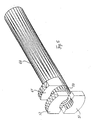
- the mechanism for locking a container on one Chassis essentially has a mushroom shape Locking bolt 21, which in the conventional manner and Is designed. It is so in its dimensions dimensioned that it fits into the fitting of a container from introduced below, rotated 90 ° there and again in Clamping position can be lowered. That way it creates a transport - safe connection between the Fitting the container and the associated chassis one Vehicle.
- the locking bolt 21 is supported on two support parts 20, and these are known parts a lock.
- the mechanism according to the invention shown in the figures ensures that locking movements of the Locking bolt 21 can be executed.
- the Locking bolt 21 can be together with its two Support parts 20 are lowered so that he with his upper extent not over the loading level of the chassis protrudes beyond.
- the locking bolt 21st by means of a piston rod 40 of a piston-cylinder arrangement (not shown in FIGS. 1 to 8, recognizable in FIG. 9) actuated, all his movements as they preceded have been described, and also the lowering process an essentially reciprocating movement of the Piston rod 40 are derived.
- Fig. 1 the mechanism is in the lowered position shown and this location is characterized in that Side walls 10 and support lever arms 12 of the mechanism with their respective lower areas together on one shown edition below the transport level of the Rest the vehicle.
- the mechanism has further parts 10 and 12 lying face down on its other side.
- the push rod 15 is shown in FIG. 1 between an upper Projection or pull cams 52 of a rod 40 and one another projection or pressure cam 61 of a tube 60. Die corresponding position of the cams is also in Fig. 5 too detect. It is shown there as at the free end of the hollow Rod 50 the upward projection 52 and one behind projection 51 below is present.
- the outer Tube 60 is only equipped with the protrusion 61, which in Fig. 5 points upwards and in Fig. 6 points downwards, the So not only back and forth, but also around Pipe axis is pivotable.
- the rod 50 and the tube 60 are telescopic to one another arranged and connected to the piston rod 40, so that the projections 51, 52 and 61 the movements of the Join the piston rod 40 when it comes out of the piston cylinder assembly moves in or out. this will are described below.
- FIGs 1 to 3 are still two in Shear parts 30 aligned in the longitudinal direction are shown, which via a transverse push rod 31 to form a unit are interconnected.
- the push rod 31 and so also the push parts 30 can be moved back and forth and act on the locking bolt 21 at the lower end , as is the case, for example, in WO 00/51842 has been described so that this rotary motion around executes its longitudinal axis.
- On the push part 30 is accordingly a rack part and an inclined plane trained so that by back and forth movements of the Push part 30 the locking bolt 21 one up directed axial movement, but also a rotary movement around its axis can be given in the range of 90 °.
- Fig. 1 the starting position is shown, i.e. the Locking bolt 21 is retracted and the mechanism i.e. parts 10 to 13, 30 and 31 are in the lower layer, i.e. the lower position.
- a guide member 70 can still be seen, the fixed between the projections 51 and 52 of the rod 50 is and guided on guides 32 on the thrust members 30 becomes.
- the projection 61 of the tube 60 relative to the rod 50 and the projections 51 and 52 can be pivoted through 180 °.
- the two telescopic parts 50 and 60 can don't just make axial movements, they're over it also capable of relative rotary movements around the to carry out your own axis, and simply by Movements of the piston rod connected to the rod 50 40th
- Such a movement implementation can be done accomplish that on one of the parts 50 and 60 inside there is a coiled track, which in turn is marked by a complementary sensing part on the other part 60 or 50 is sensed, for example by two to each other Complementarily trained traces or through an over the circumferential slot, which with the help of a Radial pin is sensed.
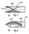
- FIGS. 7 and 8 are top views of a piece of pipe 1010, which is used to control the Pivotal movement of the projection 61 of the tube 60 relative to the projections 52 and 51 of the rod 50 to accomplish.
- Fig. 7 shows the pipe section 1010 with a coiled Track 101, which is 180 ° over the circumference of the pipe section 1010 stretches.
- Track 101 ends in the lower right part of the pipe section 1010 shown in Fig. 7 and has in End region in the form of an elongated hole, as is the case with 101 in 8 is shown in broken lines.
- At 102 is an axially extending edge with a flat surface designated, which in a way the opposite Represents boundary to lane 101.
- the pipe section 1010 is designed with two appropriately Tracks 101 and 102 equipped, each by 180 ° offset, which is indicated in Fig. 7 by 101 '.
- the sleeve 1010 in one position shows rotated by 90 °, the edge 102 'can be seen and also the curved configuration of the track 101 '.
- FIGS. 7 and 8 shown sleeves and sets these two when considering the 7 and 8 axially aligned, but mirror image together, it can be seen that these two sleeves are two Relative to each other can take the 180 ° are pivoted to each other.
- the two sleeves can take these rotational positions one after the other take by moving them axially to each other, whereby the interlocking tracks 102 and 102 'of the two opposite axial sleeves this axial movement to ensure.
- Such a mechanism is now used to get out axial movements of the tube 60 pivotal movements of the Derive cam 61.
- the locking bolt 21 is in its lower part with a Pinion formed, and it can be seen if in this Pinion meshes a gear or rack, the locking bolt performs a rotational movement.
- the locking bolt 21 is in its lower part a ramp formed in relation to the outer surface of the locking bolt is tangential. It is it can be seen that when this ramp is acted on, the Bolt carries out axial movements.
- the locking bolt 21 can perform these movements carry out if it is supported axially and radially is, it performs the axial movements, without doing so to affect the engagement of the rack in the pinion.
- Fig. 9 leaves the device already described from a recognizing another point of view, so to speak, points to the other side the device shown in Figures 1 to 4.
- a spring part 100 can be seen in FIG Extends in the longitudinal direction and in the area of the drive is also attached to the housing.
- the free one Part is provided with a kind of bolt or pin at 101 and this protrudes in the way of moving while tensioning Parts of the latch mechanism inside. This then means that in the event of pressure loss, the individual parts of the locking mechanism for example not from the tension position, the transport position of a container. If the moves Pressure cam 61 out of this clamping position, namely under the influence of the pressure medium, he can accordingly Push the designed bolt 101 sideways, at Direction of view of Fg. 9 to the left, so that the further Movement path for the pressure cam 61 is released.
Landscapes
- Engineering & Computer Science (AREA)
- Mechanical Engineering (AREA)
- Transportation (AREA)
- Actuator (AREA)
- Transmission Devices (AREA)
- Transition And Organic Metals Composition Catalysts For Addition Polymerization (AREA)
- Reciprocating Conveyors (AREA)
- Fluid-Damping Devices (AREA)
- Fire-Extinguishing By Fire Departments, And Fire-Extinguishing Equipment And Control Thereof (AREA)
- Lock And Its Accessories (AREA)
Description
- Fig. 1
- zeigt in schaubildlicher Ansicht von rechts her gesehen einen Mechanismus zum Verriegeln eines Containers an einem Fahrzeug, wobei derjenige Zustand gezeigt ist, in welchem der Verriegelungsbolzen sich in abgesenkter Lage befindet, also nicht über die Transportebene des aufnehmenden Fahrzeugs hinaus vorsteht.
- Fig. 2
- zeigt in schaubildlicher Ansicht von rechts her gesehen einen Mechanismus zum Verriegeln eines Containers an einem Fahrzeug, wobei der Mechanismus in einer Lage wiedergegeben ist, in welcher der Verriegelungsbolzen und zugehörige Teile nach oben hin ausgefahren sind.
- Fig. 3
- zeigt in schaubildlicher Ansicht von rechts her gesehen einen Mechanismus zum Verriegeln eines Containers an einem Fahrzeug, wobei der Verriegelungsbolzen um seine Längsachse um 90° gedreht gezeigt ist, um in dieser Lage einen nicht gezeigten Container für den Transport zu haltern.
- Fig. 4
- zeigt in schaubildlicher Ansicht von links her gesehen einen Mechanismus zum Verriegeln eines Containers an einem Fahrzeug, wobei die Ansicht die Situation wiedergibt kurz vor dem Verriegeln eines Beschlages bzw. kurz nach dem Entriegeln eines Beschlages eines nicht gezeigten Containers.
- Fig. 5
- zeigt die schaubildliche Lage der teleskopierenden Teile des Mechanismus nach den Figuren 1 bis 3 in einer ersten Eingriffslage.
- Fig. 6
- zeigt die schaubildliche Lage der teleskopierenden Teile nach Fig. 5 in der anderen Eingriffslage.
- Fig. 7
- zeigt eine Draufsicht auf eine Spiralhülse im Inneren der teleskopierenden Teile.
- Fig. 8
- zeigt eine Draufsicht auf die Spiralhülse nach Fig. 7, jedoch um 90° verschwenkt.
- Fig. 9
- zeigt in verändertem Maßstab die in den vorangehenden Figuren beschriebenen Teile, jedoch von der gegenüberliegenden Seite her betrachtet, und lässt einen Sperrmechanismus erkennen, der bei Druckluftabfall wirksam wird.
Claims (3)
- Vorrichtung zum selektiven Hin- und Herbewegen von Antriebsteilen eines Mechanismus zum Anheben, Absenken und Drehen eines Verriegelungsbolzens zur Verriegelung mit einem Beschlag eines Containers vermittels einer Druckmittel betätigten Kolbenzylinderanordnung, dadurch gekennzeichnet, dass auf der Kolbenstange (40) des Druckmittelzylinders zwei teleskopierende Teile (50, 60) koaxial zur Kolbenstange (40) angeordnet sind; eine innere zylinderförmig ausgebildete Stange (50) auf der Kolbenstange (40) drehfest angeordnet und am freien Ende entweder mit einem flanschartigem Vorsprung oder mit zwei nach oben und nach unten radial nach außen vorspringenden Teilen (51, 52) ausgebildet ist, mit dessen/deren Hilfe zum Druckmittelzylinder hin gerichtete Bewegungen, also Zugbewegungen ausführbar sind; dass ein äußeres die Stange (50) umgebendes Rohr (60) am freien Ende mit einem radial nach außen vorstehendem Vorsprung (61) ausgebildet ist, mit dessen Hilfe vom Druckmittelzylinder weg gerichtete Bewegungen, also Druckbewegungen, ausführbar sind; und dass die Stange (50) und das Rohr (60) in zwei Drehstellungen zueinander in Eingriff bringbar sind, wobei in der einen der Vorsprung (61) des Rohres (60) sich oben und in der anderen sich unten befindet.
- Verfahren zum selektiven Hin- und Herbewegen von Antriebsteilen eines Riegelmechanismus für die Transportsicherung eines Frachtcontainers auf einem Chassis eines Fahrzeuges vermittels einer druckmittelbetätigten Kolbenzylinderanordnung (40), dadurch gekennzeichnet, dass mittels einer Einfahrbewegung der Kolbenstange (40) ein mit ihr arbeitsmäßig verbundener Zugnocken (52) durch translatorische Bewegung und über eine daraus abgeleitete Schwenkbewegung eines Drehhebels (12,14) den Riegelmechanismus unter Einschluss des Riegelbolzens (21) in die ausgefahrene Position anhebt und dass mittels einer folgenden Ausfahrbewegung der Kolbenstange (50) ein mit ihr arbeitsmäßig verbundener Drucknocken (61) zunächst den Drucknocken um 180° verschwenkt und sodann durch translatorische Bewegung über eine Zahnstange und eine schiefe Ebene den Riegelbolzen (21) um seine Achse um 90° dreht und in die Spannposition bzw. Transportlage des Containers absenkt.
- Verfahren nach Anspruch 2, dadurch gekennzeichnet, dass mittels einer Einfahrbewegung der Kolbenstange (40) der mit ihr arbeitsmäßig verbundene Zugnocken (52) durch translatorische Bewegung über die schiefe Ebene und die zahnstange den Riegelbolzen (21) anhebt und um 90° um seine Achse dreht, und dass mittels einer weiteren Einfahrbewegung der Kolbenstange (40) der mit ihr arbeitsmäßig verbundene Drucknocken (61) zunächst den Drucknocken um 180° verschwenkt und sodann durch eine folgende Ausfahrbewegung über eine daraus abgeleitete Schwenkbewegung des Drehhebels (12,14) der Riegelmechanismus unter Einschluss des Riegelbolzens (21) in die eingefahrene Position abgesenkt wird.
Applications Claiming Priority (4)
| Application Number | Priority Date | Filing Date | Title |
|---|---|---|---|
| DE20104737 | 2001-03-20 | ||
| DE20104737U | 2001-03-20 | ||
| DE20119415U | 2001-11-30 | ||
| DE20119415U DE20119415U1 (de) | 2001-11-30 | 2001-11-30 | Vorrichtung zum selektiven Hin- und Herbewegen von Antriebsteilen eines Mechanismus vermittels einer Druckmittel betätigten Kolbenzylinderanordnung |
Publications (3)
| Publication Number | Publication Date |
|---|---|
| EP1243466A2 EP1243466A2 (de) | 2002-09-25 |
| EP1243466A3 EP1243466A3 (de) | 2002-10-23 |
| EP1243466B1 true EP1243466B1 (de) | 2003-10-22 |
Family
ID=26056869
Family Applications (1)
| Application Number | Title | Priority Date | Filing Date |
|---|---|---|---|
| EP02006153A Expired - Lifetime EP1243466B1 (de) | 2001-03-20 | 2002-03-19 | Transportsicherung für Frachtcontainer |
Country Status (3)
| Country | Link |
|---|---|
| EP (1) | EP1243466B1 (de) |
| AT (1) | ATE252467T1 (de) |
| DE (1) | DE50200078D1 (de) |
Cited By (3)
| Publication number | Priority date | Publication date | Assignee | Title |
|---|---|---|---|---|
| CN113479129A (zh) * | 2021-08-16 | 2021-10-08 | 郑州市颖达热力工程设计院 | 一种自动装卸式移动储热车及其工作方法 |
| DE102021115027A1 (de) | 2021-06-10 | 2022-12-15 | Hamburger Patent Schmiede Gmbh | Absenkbare Containerverriegelung |
| WO2023169623A1 (de) | 2022-03-08 | 2023-09-14 | Hamburger Patent Schmiede Gmbh | Anhebe- und absenkanordnung für containerverriegelung und anhebe- und absenkverfahren damit |
Families Citing this family (13)
| Publication number | Priority date | Publication date | Assignee | Title |
|---|---|---|---|---|
| ATE473131T1 (de) * | 2007-02-08 | 2010-07-15 | 1 Rmm Entwicklungsgmbh & Co Kg | Verriegelung für einen container auf einem fahrzeug |
| DE102009044222A1 (de) * | 2009-10-09 | 2011-04-28 | Wihag Fahrzeugbausysteme Gmbh | Verriegelungsvorrichtung |
| CN106103187A (zh) * | 2014-02-19 | 2016-11-09 | 米杰克产品有限公司 | 用于将集装箱自动固定至集装箱底盘车的闩锁系统 |
| US9463732B2 (en) | 2014-02-19 | 2016-10-11 | Mi-Jack Products, Inc. | Latching system for automatic securement of a container to a container chassis |
| US9387792B2 (en) | 2014-02-19 | 2016-07-12 | Mi-Jack Products, Inc. | Latching system for automatic securement of a container to a container chassis |
| US9340146B2 (en) | 2014-02-19 | 2016-05-17 | Mi-Jack Products, Inc. | Front pin latching system for automatic securement of a container to a container chassis |
| US9969318B2 (en) | 2016-04-27 | 2018-05-15 | Mi-Jack Products, Inc. | Locking system for securing a container |
| US11752924B2 (en) | 2021-01-05 | 2023-09-12 | Mi-Jack Products, Inc. | Latching device and method for automatic securement of a container to a container chassis |
| US11685353B2 (en) | 2021-01-05 | 2023-06-27 | Mi-Jack Products, Inc. | Systems and method for securement of a container to a vehicle having a brake system |
| DE102021112894A1 (de) * | 2021-05-18 | 2022-11-24 | Hamburger Patent Schmiede Gmbh | Containerverriegelungsvorrichtung sowie Containerverriegelungsverfahren |
| DE102021122625A1 (de) * | 2021-09-01 | 2023-03-02 | Hamburger Patent Schmiede Gmbh | Containerverriegelungsvorrichtung sowie Containerverriegelungsverfahren |
| CN116461863B (zh) * | 2023-04-23 | 2025-08-29 | 上海凡顺实业股份有限公司 | 一种集装箱锁销自动拆装夹具解锁机构 |
| CN116280756B (zh) * | 2023-04-23 | 2025-09-02 | 上海凡顺实业股份有限公司 | 一种集装箱锁销自动拆装夹具 |
Family Cites Families (4)
| Publication number | Priority date | Publication date | Assignee | Title |
|---|---|---|---|---|
| US3892436A (en) * | 1974-04-11 | 1975-07-01 | Midland Ross Corp | Retractable latch mechanism for cargo container spreaders |
| DE3038461A1 (de) | 1980-10-11 | 1982-05-19 | Gerd Schulz Fahrzeug- und Container-Technik, 2100 Hamburg | Vorrichtung zum insbesondere stirnseitigen verriegeln von containern |
| DE19718528C1 (de) * | 1997-05-02 | 1998-12-03 | Fahrzeugtechnik Dessau Gmbh | Einrichtung zum Befestigen von Behältern auf Tragfahrzeugen, insbesondere zum Verriegeln von Containern auf Eisenbahnwagen |
| DE29903940U1 (de) * | 1999-03-04 | 1999-09-09 | R. Metternich Metallbau GmbH, 21107 Hamburg | Verriegelungseinrichtung für Container auf dem Chassis eines Fahrzeuges |
-
2002
- 2002-03-19 AT AT02006153T patent/ATE252467T1/de active
- 2002-03-19 EP EP02006153A patent/EP1243466B1/de not_active Expired - Lifetime
- 2002-03-19 DE DE50200078T patent/DE50200078D1/de not_active Expired - Lifetime
Cited By (5)
| Publication number | Priority date | Publication date | Assignee | Title |
|---|---|---|---|---|
| DE102021115027A1 (de) | 2021-06-10 | 2022-12-15 | Hamburger Patent Schmiede Gmbh | Absenkbare Containerverriegelung |
| WO2022258112A1 (de) | 2021-06-10 | 2022-12-15 | Hamburger Patent Schmiede Gmbh | Absenkbare containerverriegelung |
| CN113479129A (zh) * | 2021-08-16 | 2021-10-08 | 郑州市颖达热力工程设计院 | 一种自动装卸式移动储热车及其工作方法 |
| WO2023169623A1 (de) | 2022-03-08 | 2023-09-14 | Hamburger Patent Schmiede Gmbh | Anhebe- und absenkanordnung für containerverriegelung und anhebe- und absenkverfahren damit |
| DE102022105423A1 (de) | 2022-03-08 | 2023-09-14 | Hamburger Patent Schmiede Gmbh | Anhebe- und Absenkanordnung für Containerverriegelung und Anhebe- und Absenkverfahren damit |
Also Published As
| Publication number | Publication date |
|---|---|
| DE50200078D1 (de) | 2003-11-27 |
| ATE252467T1 (de) | 2003-11-15 |
| EP1243466A2 (de) | 2002-09-25 |
| EP1243466A3 (de) | 2002-10-23 |
Similar Documents
| Publication | Publication Date | Title |
|---|---|---|
| EP1243466B1 (de) | Transportsicherung für Frachtcontainer | |
| EP1925540B1 (de) | Hilfsantrieb für einen Anhänger | |
| DE69013717T2 (de) | Selbsttätige Anhaltevorrichtung für Kraftfahrzeuge, z.B. für einen Lastwagen an einer Laderampe. | |
| DE3923695C2 (de) | Vorrichtung zum Niederholen des vorderen Endes eines Fahrzeugverdecks | |
| EP1661755B1 (de) | Lastentransportfahrzeug, insbesondere Absetzkipper | |
| DE69507395T2 (de) | Ein höhenverstellbarer Zughaken für Sattelkupplungen | |
| EP1197369A2 (de) | Windschott für ein Cabriolet-Fahrzeug | |
| DE2754009A1 (de) | Fahrzeug zum transportieren von lasten | |
| AT516739B1 (de) | Fahrzeugaufbau | |
| DE3619677C1 (de) | Vorrichtung zum Heben und Senken des Kopf- und des Fussteiles eines Bettrahmens | |
| DE2736222C3 (de) | Hubfangverschluß | |
| DE102015207799A1 (de) | Unterfahrschutzeinrichtung mit Verstellvorrichtung und Fahrzeug umfassend eine solche Unterfahrschutzeinrichtung | |
| EP4201192A1 (de) | Ladungssicherungsvorrichtung für landwirtschaftliche transportwagen | |
| DE2660637C2 (de) | Transportgeraet, bestehend aus einem austaschbaren behaelter und einem transportfahrzeug | |
| DE2317553C2 (de) | Vorrichtung zum Öffnen des Deckels beim Entleeren von Behältern, beispielsweise Müllgefässen | |
| DE4301055A1 (de) | Zugdeichselanordnung | |
| DE19630897A1 (de) | Anhängerkupplung | |
| DE2914718A1 (de) | Vorrichtung zum befestigen von lastentraegern auf eisenbahnwagen | |
| EP4489995B1 (de) | Anhebe- und absenkanordnung für containerverriegelung und anhebe- und absenkverfahren damit | |
| DE2841022A1 (de) | Arretiervorrichtung fuer ein verschwenkbares element, insbesondere fuer einen verschwenkbaren tragarm einer hebebuehne fuer kraftfahrzeuge | |
| DE20119415U1 (de) | Vorrichtung zum selektiven Hin- und Herbewegen von Antriebsteilen eines Mechanismus vermittels einer Druckmittel betätigten Kolbenzylinderanordnung | |
| DE202011002919U1 (de) | Vorrichtung zum Überführen einer Wand eines Transportbehälters | |
| CH652668A5 (en) | Transport vehicle with an interchangeable body | |
| DE19952483C1 (de) | Verriegelungsvorrichtung für nebeneinander angeordnete Hubwagen | |
| WO1998008720A1 (de) | Vorrichtung zur sicherung eines gegenstandes auf einem fahrzeug |
Legal Events
| Date | Code | Title | Description |
|---|---|---|---|
| PUAI | Public reference made under article 153(3) epc to a published international application that has entered the european phase |
Free format text: ORIGINAL CODE: 0009012 |
|
| PUAL | Search report despatched |
Free format text: ORIGINAL CODE: 0009013 |
|
| AK | Designated contracting states |
Kind code of ref document: A2 Designated state(s): AT BE CH CY DE DK ES FI FR GB GR IE IT LI LU MC NL PT SE TR |
|
| AX | Request for extension of the european patent |
Free format text: AL;LT;LV;MK;RO;SI |
|
| AK | Designated contracting states |
Kind code of ref document: A3 Designated state(s): AT BE CH CY DE DK ES FI FR GB GR IE IT LI LU MC NL PT SE TR |
|
| AX | Request for extension of the european patent |
Free format text: AL;LT;LV;MK;RO;SI |
|
| 17P | Request for examination filed |
Effective date: 20020919 |
|
| 17Q | First examination report despatched |
Effective date: 20021216 |
|
| GRAH | Despatch of communication of intention to grant a patent |
Free format text: ORIGINAL CODE: EPIDOS IGRA |
|
| AKX | Designation fees paid |
Designated state(s): AT BE CH CY DE DK ES FI FR GB GR IE IT LI LU MC NL PT SE TR |
|
| GRAS | Grant fee paid |
Free format text: ORIGINAL CODE: EPIDOSNIGR3 |
|
| GRAA | (expected) grant |
Free format text: ORIGINAL CODE: 0009210 |
|
| AK | Designated contracting states |
Kind code of ref document: B1 Designated state(s): AT BE CH CY DE DK ES FI FR GB GR IE IT LI LU MC NL PT SE TR |
|
| PG25 | Lapsed in a contracting state [announced via postgrant information from national office to epo] |
Ref country code: IT Free format text: LAPSE BECAUSE OF FAILURE TO SUBMIT A TRANSLATION OF THE DESCRIPTION OR TO PAY THE FEE WITHIN THE PRESCRIBED TIME-LIMIT;WARNING: LAPSES OF ITALIAN PATENTS WITH EFFECTIVE DATE BEFORE 2007 MAY HAVE OCCURRED AT ANY TIME BEFORE 2007. THE CORRECT EFFECTIVE DATE MAY BE DIFFERENT FROM THE ONE RECORDED. Effective date: 20031022 Ref country code: IE Free format text: LAPSE BECAUSE OF FAILURE TO SUBMIT A TRANSLATION OF THE DESCRIPTION OR TO PAY THE FEE WITHIN THE PRESCRIBED TIME-LIMIT Effective date: 20031022 Ref country code: FR Free format text: LAPSE BECAUSE OF FAILURE TO SUBMIT A TRANSLATION OF THE DESCRIPTION OR TO PAY THE FEE WITHIN THE PRESCRIBED TIME-LIMIT Effective date: 20031022 Ref country code: GB Free format text: LAPSE BECAUSE OF FAILURE TO SUBMIT A TRANSLATION OF THE DESCRIPTION OR TO PAY THE FEE WITHIN THE PRESCRIBED TIME-LIMIT Effective date: 20031022 Ref country code: NL Free format text: LAPSE BECAUSE OF FAILURE TO SUBMIT A TRANSLATION OF THE DESCRIPTION OR TO PAY THE FEE WITHIN THE PRESCRIBED TIME-LIMIT Effective date: 20031022 Ref country code: TR Free format text: LAPSE BECAUSE OF FAILURE TO SUBMIT A TRANSLATION OF THE DESCRIPTION OR TO PAY THE FEE WITHIN THE PRESCRIBED TIME-LIMIT Effective date: 20031022 Ref country code: FI Free format text: LAPSE BECAUSE OF FAILURE TO SUBMIT A TRANSLATION OF THE DESCRIPTION OR TO PAY THE FEE WITHIN THE PRESCRIBED TIME-LIMIT Effective date: 20031022 Ref country code: CY Free format text: LAPSE BECAUSE OF FAILURE TO SUBMIT A TRANSLATION OF THE DESCRIPTION OR TO PAY THE FEE WITHIN THE PRESCRIBED TIME-LIMIT Effective date: 20031022 |
|
| REG | Reference to a national code |
Ref country code: GB Ref legal event code: FG4D Free format text: NOT ENGLISH |
|
| REG | Reference to a national code |
Ref country code: CH Ref legal event code: EP |
|
| REG | Reference to a national code |
Ref country code: IE Ref legal event code: FG4D Free format text: GERMAN |
|
| REF | Corresponds to: |
Ref document number: 50200078 Country of ref document: DE Date of ref document: 20031127 Kind code of ref document: P |
|
| PG25 | Lapsed in a contracting state [announced via postgrant information from national office to epo] |
Ref country code: GR Free format text: LAPSE BECAUSE OF FAILURE TO SUBMIT A TRANSLATION OF THE DESCRIPTION OR TO PAY THE FEE WITHIN THE PRESCRIBED TIME-LIMIT Effective date: 20040122 Ref country code: DK Free format text: LAPSE BECAUSE OF FAILURE TO SUBMIT A TRANSLATION OF THE DESCRIPTION OR TO PAY THE FEE WITHIN THE PRESCRIBED TIME-LIMIT Effective date: 20040122 Ref country code: SE Free format text: LAPSE BECAUSE OF FAILURE TO SUBMIT A TRANSLATION OF THE DESCRIPTION OR TO PAY THE FEE WITHIN THE PRESCRIBED TIME-LIMIT Effective date: 20040122 |
|
| PG25 | Lapsed in a contracting state [announced via postgrant information from national office to epo] |
Ref country code: ES Free format text: LAPSE BECAUSE OF FAILURE TO SUBMIT A TRANSLATION OF THE DESCRIPTION OR TO PAY THE FEE WITHIN THE PRESCRIBED TIME-LIMIT Effective date: 20040202 |
|
| REG | Reference to a national code |
Ref country code: CH Ref legal event code: NV Representative=s name: KIRKER & CIE SA |
|
| PG25 | Lapsed in a contracting state [announced via postgrant information from national office to epo] |
Ref country code: LU Free format text: LAPSE BECAUSE OF NON-PAYMENT OF DUE FEES Effective date: 20040319 |
|
| PG25 | Lapsed in a contracting state [announced via postgrant information from national office to epo] |
Ref country code: MC Free format text: LAPSE BECAUSE OF NON-PAYMENT OF DUE FEES Effective date: 20040331 |
|
| NLV1 | Nl: lapsed or annulled due to failure to fulfill the requirements of art. 29p and 29m of the patents act | ||
| GBV | Gb: ep patent (uk) treated as always having been void in accordance with gb section 77(7)/1977 [no translation filed] |
Effective date: 20031022 |
|
| REG | Reference to a national code |
Ref country code: IE Ref legal event code: FD4D |
|
| PLBE | No opposition filed within time limit |
Free format text: ORIGINAL CODE: 0009261 |
|
| STAA | Information on the status of an ep patent application or granted ep patent |
Free format text: STATUS: NO OPPOSITION FILED WITHIN TIME LIMIT |
|
| 26N | No opposition filed |
Effective date: 20040723 |
|
| EN | Fr: translation not filed | ||
| PG25 | Lapsed in a contracting state [announced via postgrant information from national office to epo] |
Ref country code: PT Free format text: LAPSE BECAUSE OF NON-PAYMENT OF DUE FEES Effective date: 20040322 |
|
| PGFP | Annual fee paid to national office [announced via postgrant information from national office to epo] |
Ref country code: CH Payment date: 20110328 Year of fee payment: 10 Ref country code: AT Payment date: 20110323 Year of fee payment: 10 |
|
| PGFP | Annual fee paid to national office [announced via postgrant information from national office to epo] |
Ref country code: BE Payment date: 20110328 Year of fee payment: 10 |
|
| BERE | Be: lapsed |
Owner name: *HAMBURGER PATENT SCHMIEDE G.M.B.H. Effective date: 20120331 |
|
| REG | Reference to a national code |
Ref country code: CH Ref legal event code: PL |
|
| REG | Reference to a national code |
Ref country code: AT Ref legal event code: MM01 Ref document number: 252467 Country of ref document: AT Kind code of ref document: T Effective date: 20120319 |
|
| PG25 | Lapsed in a contracting state [announced via postgrant information from national office to epo] |
Ref country code: LI Free format text: LAPSE BECAUSE OF NON-PAYMENT OF DUE FEES Effective date: 20120331 Ref country code: AT Free format text: LAPSE BECAUSE OF NON-PAYMENT OF DUE FEES Effective date: 20120319 Ref country code: CH Free format text: LAPSE BECAUSE OF NON-PAYMENT OF DUE FEES Effective date: 20120331 Ref country code: BE Free format text: LAPSE BECAUSE OF NON-PAYMENT OF DUE FEES Effective date: 20120331 |
|
| PGFP | Annual fee paid to national office [announced via postgrant information from national office to epo] |
Ref country code: DE Payment date: 20130312 Year of fee payment: 12 |
|
| REG | Reference to a national code |
Ref country code: DE Ref legal event code: R119 Ref document number: 50200078 Country of ref document: DE |
|
| REG | Reference to a national code |
Ref country code: DE Ref legal event code: R119 Ref document number: 50200078 Country of ref document: DE Effective date: 20141001 |
|
| PG25 | Lapsed in a contracting state [announced via postgrant information from national office to epo] |
Ref country code: DE Free format text: LAPSE BECAUSE OF NON-PAYMENT OF DUE FEES Effective date: 20141001 |