EP1243362A2 - Procédé et dispositif de fabrication de feuillard à chaud dans une machine de coulée continue de type à deux rouleaux - Google Patents
Procédé et dispositif de fabrication de feuillard à chaud dans une machine de coulée continue de type à deux rouleaux Download PDFInfo
- Publication number
- EP1243362A2 EP1243362A2 EP02006223A EP02006223A EP1243362A2 EP 1243362 A2 EP1243362 A2 EP 1243362A2 EP 02006223 A EP02006223 A EP 02006223A EP 02006223 A EP02006223 A EP 02006223A EP 1243362 A2 EP1243362 A2 EP 1243362A2
- Authority
- EP
- European Patent Office
- Prior art keywords
- hot strip
- strip
- skins
- thickness
- casting
- Prior art date
- Legal status (The legal status is an assumption and is not a legal conclusion. Google has not performed a legal analysis and makes no representation as to the accuracy of the status listed.)
- Withdrawn
Links
Images


Classifications
-
- B—PERFORMING OPERATIONS; TRANSPORTING
- B22—CASTING; POWDER METALLURGY
- B22D—CASTING OF METALS; CASTING OF OTHER SUBSTANCES BY THE SAME PROCESSES OR DEVICES
- B22D11/00—Continuous casting of metals, i.e. casting in indefinite lengths
- B22D11/06—Continuous casting of metals, i.e. casting in indefinite lengths into moulds with travelling walls, e.g. with rolls, plates, belts, caterpillars
- B22D11/0622—Continuous casting of metals, i.e. casting in indefinite lengths into moulds with travelling walls, e.g. with rolls, plates, belts, caterpillars formed by two casting wheels
-
- B—PERFORMING OPERATIONS; TRANSPORTING
- B22—CASTING; POWDER METALLURGY
- B22D—CASTING OF METALS; CASTING OF OTHER SUBSTANCES BY THE SAME PROCESSES OR DEVICES
- B22D11/00—Continuous casting of metals, i.e. casting in indefinite lengths
- B22D11/06—Continuous casting of metals, i.e. casting in indefinite lengths into moulds with travelling walls, e.g. with rolls, plates, belts, caterpillars
- B22D11/0637—Accessories therefor
- B22D11/0648—Casting surfaces
- B22D11/0651—Casting wheels
-
- B—PERFORMING OPERATIONS; TRANSPORTING
- B21—MECHANICAL METAL-WORKING WITHOUT ESSENTIALLY REMOVING MATERIAL; PUNCHING METAL
- B21B—ROLLING OF METAL
- B21B1/00—Metal-rolling methods or mills for making semi-finished products of solid or profiled cross-section; Sequence of operations in milling trains; Layout of rolling-mill plant, e.g. grouping of stands; Succession of passes or of sectional pass alternations
- B21B1/46—Metal-rolling methods or mills for making semi-finished products of solid or profiled cross-section; Sequence of operations in milling trains; Layout of rolling-mill plant, e.g. grouping of stands; Succession of passes or of sectional pass alternations for rolling metal immediately subsequent to continuous casting
- B21B1/463—Metal-rolling methods or mills for making semi-finished products of solid or profiled cross-section; Sequence of operations in milling trains; Layout of rolling-mill plant, e.g. grouping of stands; Succession of passes or of sectional pass alternations for rolling metal immediately subsequent to continuous casting in a continuous process, i.e. the cast not being cut before rolling
Definitions
- the invention relates to a method and an apparatus for producing Hot strip using two-roll thin strip casting machines, with molten steel between two counter rotating casting rolls is introduced and during the Rotational movement of the two casters on the circumferential surface of the same two Stranded skin, each with a thickness "s", which in turn solidifies as a result of Rotational movement moves down and in a so-called kiss point the hot strip are pressed together and then completely solidified hot strip in a rolling mill in one or more passes the finally rolled strip having the desired thickness range is formed becomes.
- Thin strip casting plants for the production of hot broadband in the usual width range of about 800 to 1,400 mm and thickness range of about 2 to 5 mm are known in practice, casting rolls with constant diameter and different bale lengths being used because the Bandwidth is essentially determined by the bale length of the same.
- the casting roll diameter is approximately 0.6 to 1.5 m.
- the thickness "d" of the hot strip is subsequently reduced in a rolling mill by at least 5% to a strip close to the final dimension or having the desired final dimension.
- the object of the invention is a method and an apparatus for producing To specify hot strip by means of two-roll thin strip casting machines, with which one substantial increase in production throughput "P" over that by the Solidification time "t" of the skins set limits for conventional two-roll thin-strip casting plants is possible.
- the task is in connection with the features in the preamble of claim 1 solved by a method, the two within the Extruded skins formed in such a way in sections on two-roll thin-strip caster defined to be pressed together or spaced apart from each other Forms hot strip with locally limited and variable material cross-sections.
- the skins in the transition areas be punctiform, line and / or surface to compress.
- the two skins in sections defines to squeeze or space apart that one Hot strip with a plurality of approximately parallel to each other and in Flow direction of the hot strip arranged strip-shaped surface elements formed.
- section the two strand skins in this way defines to squeeze or space apart that one Hot strip with a plurality of approximately parallel to and around one certain angle " ⁇ " pivoted to the flow direction of the hot strip arranged strip-shaped surface elements.
- the device for the production of hot strip by means of two-roll thin strip casting machines is characterized in that for the production of a Hot strip with defined, locally limited and variable material cross sections one of the two or both casting rolls has a peripheral surface structure different and defined changes in diameter "D" exhibit.
- a further development of the device according to the invention provides that one of the both or both casting rolls have such a peripheral surface structure that the two skins of the hot strip leaving the kiss point, one A plurality of merging uniformly and / or non-uniformly Forming designed surface elements, pressed together in sections in a defined manner or are spaced from each other.
- one of the two or both Casting rolls have such a peripheral surface structure that the strand skins in the transition areas are pressed in a point, line and / or area shape are.
- one of the two or both casting rolls can be one Have peripheral surface structure that the leaving the kiss point Hot strip, a plurality of merging and approximately parallel to each other and in the flow direction of the hot strip or by an angle " ⁇ " to Flow direction of the hot strip pivoted strip-shaped Includes surface elements.
- Another inventive measure provides that the individual surface elements the hot strip has a maximum extension "b" in at least one direction have about 15 times the thickness "s" of the strand skin.
- the roll gap of the roll stand in the rolling mill is for set the first rolling pass so that both for the thick sections of the Hot strip as well as for the thinnest sections of the same There is a decrease in cross-section.
- the device for the production of hot strip 1 consists of a two-roll thin strip caster 2, which has a feed device for liquid steel 3 in the form of a turret 4 for receiving the ladle 5 with an intermediate container 6, which in turn is a dip tube 7 and one not closer Plug mechanism shown for controlling the supply of the liquid steel 3 in the two-roll thin-strip caster 2 arranged vertically below the intermediate container 6, is arranged upstream.
- the two-roll thin-strip casting installation 2 is followed by a discharge part 8, consisting, for example, of a roller strip guide for the cast hot strip 1, and a rolling mill 9 and / or at least one reel, which is not shown in detail, but is known per se.
- the rolling mill 9 can have one roll stand or also a plurality of roll stands.
- the two-roll thin strip caster 2 consists of two counter-rotating and optionally cooled casting rolls 10, which by means side seals (not shown), for example in the form of ceramic Plates, form a funnel 11 for receiving the liquid steel 3.
- the liquid steel 3 is fed to the two-roll thin-strip casting installation 2 by means of the dip tube 7 and, as already mentioned, forms a steel bath 12 with the bath level 13 in the funnel 11 which is closed off at the side, the height of which is also referred to as the solidification length "I” and by the bath level angle ⁇ "is defined (" ⁇ "in radians).
- the hot strip 1 then leaves the two-roll thin strip caster 1 at the casting speed "v", which in turn corresponds to the peripheral speed of the casting rolls 10.
- the solidification rate for metals at the phase boundary solid / liquid is proportional to the temperature gradient in the solidified material at the phase boundary and this in turn is approximately equal to the temperature gradient in the already solidified layer from the phase boundary to the outer skin (Groeber , Erk, Grigall; The Basic Laws of Heat Transfer).
- the surface temperature in the solidified strand skin after the initial solidification in a mold is approximately constant.
- the temperature gradient in the solidified strand skin and thus also in the phase boundary becomes ever smaller with increasing strand skin thickness.
- two-roll thin strip casting is thus apparently a relatively "rigid” process in which the production throughput "P" is predetermined within narrow limits by the bandwidth "B” and the diameter "D” of the casting rolls 10. Accordingly, for a desired bandwidth "B”, the production throughput "P” can apparently only be changed by changing the diameter "D” of the casting rolls 10, apart from small changes which can be achieved by changing the casting level angle " ⁇ " and are around 10%.
- each casting roll 10 a plurality of on its peripheral surface Circumferential groove-shaped recesses 16 arranged parallel to one another have, as in the present case, with uniformly shaped groove-shaped recesses 16 of the opposite casting roller 10 correspond.
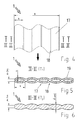
- a hot strip 1 can now be produced according to the invention by at a time “T 1 " (FIG. 2) at the level of the kissing point 15, at which a strand skin 14a; 14b with the thickness "s", they are pressed together in sections or spaced apart such that a hot strip 1 with a plurality of merging strip-shaped surface elements 17 arranged approximately parallel to one another and in the flow direction thereof is formed (FIG. 4).
- T 1 time
- the material cross section of each surface element 17 has a profile 19 that tapers at least towards the transition regions 18.
- the outer contour of this profile 19 describes a circular section, the radius of which can be chosen as desired.
- liquid steel 3 is embedded, which solidifies during the further guiding of the hot strip 1 at the casting speed "v" at the time “T 2 " (FIGS. 2 and 6).
- the skins 14a; 14b in the speech standing two-roll thin strip caster 2 in particular then not apart when the ratio of the thickness "s" of each strand skin 14a; 14b to so-called span in at least one direction does not exceed 1:15. Accordingly, it is appropriate for the individual surface elements 17 of the hot strip 1 at least in one direction with a maximum extension "b" (Fig. 4 and 6), the is to be equated with the found span, which are about that 15 times the thickness "s" of the strand skin 14a; 14b corresponds.
- a strand skin 14a; 14b with a thickness "s" of 2 mm at the kiss point 15 is thus with a maximum extension "b" (span) of 30 mm in at least one Direction through the liquid steel 3 no further apart, let alone breached.
- the skins 14a; 14b in the transition areas 18 can be pressed together in a point, line and / or area shape. It is certainly easy for the person skilled in the art to understand that the invention is not limited to the exemplary embodiment described above with a plurality of strip-shaped surface elements 17 arranged approximately parallel to one another and in the flow direction of the hot strip 1, but rather any and suitable arrangement of a plurality of merging uniformly and / or non-uniformly shaped surface elements 17 are also recorded.
- the individual skins 14a; 14b like this are pressed together in sections in a defined manner or are spaced apart from one another, that a hot strip 1 with a plurality of approximately parallel to each other and by a certain angle " ⁇ " to the flow direction of the hot strip 1 trained pivoted strip-shaped surface elements 17 forms.
- Fig. 7 shows such a hot strip 1 produced according to the invention in the Top view, an angle " ⁇ " of 90 ° has been chosen.
- the invention is not limited to surface elements 17 Profiles 19, which describe a circular section, but include any decurable and suitable profiling.
- FIGS. 8 to 11 Selected examples can be seen in FIGS. 8 to 11.
- FIG. 8 shows, for example, a triangular profile
- FIG. 9 an elliptical
- FIG. 10 a trapezoidal profile.
- the profile according to FIG. 11 differs from all those described above in that only one of the two skins 14a or 14b with the Profiling is provided, accordingly only one of the two casting rolls 10 is formed according to the invention with recesses 16 (Fig. 12).
- the decrease in the first Roll pass is to be selected in this way, or the roll gap of the roll stand for the first Roll pass is to be set so that both for the thick sections of the Hot strip 1 with the thickness "d '" as well as the thinnest sections thereof the thickness "d" (FIG. 6) shows a decrease in cross-section.
- the maximum stretching during flat rolling can be approximately 1.8. Accordingly, it must be ensured that the decrease in the first roll pass is selected such that the stretching of the sections of the hot strip 1 with the maximum thickness "d '" does not exceed 1.8. However, since for the reasons mentioned above the thinnest sections of the hot strip 1 with the thickness "d", which are arranged in the transition regions 18 of the surface elements 17, are to be deformed in the first stitch, the ratio of "d '" to "d" , which is denoted by "a”, less than 1.8.
- the profiling of the surface elements 17 is relatively free selectable and can e.g. B. by circular arcs, ellipses, triangles and / or trapezoids be educated.
- the factor a 1.7 Production throughput "P" for a given starting diameter (Diameter “D") of the casting rolls 10 for a certain bandwidth "B”
- Use of the profiles according to the invention, at least up to 1.6 times the production throughput "P" for conventional, just-made hot strips 1 increase.
Applications Claiming Priority (2)
| Application Number | Priority Date | Filing Date | Title |
|---|---|---|---|
| DE10114269 | 2001-03-22 | ||
| DE2001114269 DE10114269C1 (de) | 2001-03-22 | 2001-03-22 | Verfahren und Vorrichtung zur Herstellung von Warmband mittels Zweirollen-Dünnbandgießanlagen |
Publications (2)
| Publication Number | Publication Date |
|---|---|
| EP1243362A2 true EP1243362A2 (fr) | 2002-09-25 |
| EP1243362A3 EP1243362A3 (fr) | 2003-11-26 |
Family
ID=7678709
Family Applications (1)
| Application Number | Title | Priority Date | Filing Date |
|---|---|---|---|
| EP02006223A Withdrawn EP1243362A3 (fr) | 2001-03-22 | 2002-03-20 | Procédé et dispositif de fabrication de feuillard à chaud dans une machine de coulée continue de type à deux rouleaux |
Country Status (2)
| Country | Link |
|---|---|
| EP (1) | EP1243362A3 (fr) |
| DE (1) | DE10114269C1 (fr) |
Cited By (1)
| Publication number | Priority date | Publication date | Assignee | Title |
|---|---|---|---|---|
| US10618107B2 (en) | 2016-04-14 | 2020-04-14 | GM Global Technology Operations LLC | Variable thickness continuous casting for tailor rolling |
Families Citing this family (1)
| Publication number | Priority date | Publication date | Assignee | Title |
|---|---|---|---|---|
| DE102012109286A1 (de) | 2012-09-28 | 2014-04-03 | Outokumpu Nirosta Gmbh | Verfahren zum Erzeugen von gegossenem Band aus einer Metallschmelze und gegossenes Band |
Citations (6)
| Publication number | Priority date | Publication date | Assignee | Title |
|---|---|---|---|---|
| JPH01127148A (ja) * | 1987-11-12 | 1989-05-19 | Nippon Steel Corp | ドラム式連続鋳造装置 |
| GB2279595A (en) * | 1993-07-06 | 1995-01-11 | British Steel Plc | Continuous casting using rollers having varying radii across their width |
| EP0688620A2 (fr) * | 1994-03-24 | 1995-12-27 | Danieli United, Inc. | Machine de coulée entre deux cylindres |
| EP0740972A1 (fr) * | 1995-05-05 | 1996-11-06 | Ishikawajima-Harima Heavy Industries Co., Ltd. | Procédé et dispositif de coulée de bandes en acier |
| EP1025934A2 (fr) * | 1999-02-05 | 2000-08-09 | Ishikawajima-Harima Heavy Industries Co., Ltd. | Procédé de coulage à deux cylindres de tôle en ruban |
| DE19928836A1 (de) * | 1999-06-24 | 2000-12-28 | Wolfgang Mudersbach | Verfahren und Vorrichtung zum kontinuierlichen endlosen Gießen von endabmessungsnahen oder endabmessungsfertigen Profilquerschnitten aus Metall insbesondere Stahl zwischen zwei Gießwalzen |
-
2001
- 2001-03-22 DE DE2001114269 patent/DE10114269C1/de not_active Expired - Fee Related
-
2002
- 2002-03-20 EP EP02006223A patent/EP1243362A3/fr not_active Withdrawn
Patent Citations (6)
| Publication number | Priority date | Publication date | Assignee | Title |
|---|---|---|---|---|
| JPH01127148A (ja) * | 1987-11-12 | 1989-05-19 | Nippon Steel Corp | ドラム式連続鋳造装置 |
| GB2279595A (en) * | 1993-07-06 | 1995-01-11 | British Steel Plc | Continuous casting using rollers having varying radii across their width |
| EP0688620A2 (fr) * | 1994-03-24 | 1995-12-27 | Danieli United, Inc. | Machine de coulée entre deux cylindres |
| EP0740972A1 (fr) * | 1995-05-05 | 1996-11-06 | Ishikawajima-Harima Heavy Industries Co., Ltd. | Procédé et dispositif de coulée de bandes en acier |
| EP1025934A2 (fr) * | 1999-02-05 | 2000-08-09 | Ishikawajima-Harima Heavy Industries Co., Ltd. | Procédé de coulage à deux cylindres de tôle en ruban |
| DE19928836A1 (de) * | 1999-06-24 | 2000-12-28 | Wolfgang Mudersbach | Verfahren und Vorrichtung zum kontinuierlichen endlosen Gießen von endabmessungsnahen oder endabmessungsfertigen Profilquerschnitten aus Metall insbesondere Stahl zwischen zwei Gießwalzen |
Non-Patent Citations (1)
| Title |
|---|
| PATENT ABSTRACTS OF JAPAN vol. 013, no. 373 (M-861), 18. August 1989 (1989-08-18) -& JP 01 127148 A (NIPPON STEEL CORP;OTHERS: 01), 19. Mai 1989 (1989-05-19) * |
Cited By (1)
| Publication number | Priority date | Publication date | Assignee | Title |
|---|---|---|---|---|
| US10618107B2 (en) | 2016-04-14 | 2020-04-14 | GM Global Technology Operations LLC | Variable thickness continuous casting for tailor rolling |
Also Published As
| Publication number | Publication date |
|---|---|
| EP1243362A3 (fr) | 2003-11-26 |
| DE10114269C1 (de) | 2002-05-02 |
Similar Documents
| Publication | Publication Date | Title |
|---|---|---|
| EP1478479B1 (fr) | Procede de coulee continue et de faconnage direct d'un metal, notamment d'une barre de coulee en materiaux a base d'acier | |
| AT401744B (de) | Verfahren und anlage zum stranggiessen | |
| EP1181997A1 (fr) | Procédé et dispositif pour la coulée continue de bande d'acier à partir d'une masse d'acier en fusion | |
| DE2444443A1 (de) | Verfahren zum stranggiessen einer stahlschmelze | |
| EP0353402B1 (fr) | Procédé de production d'une bande d'acier ayant une épaisseur de moins de 10 mm | |
| DE2063591A1 (de) | Verfahren und Vorrichtung zum kon tmuierhchen Gießen von Metallen | |
| DE3440236C2 (fr) | ||
| DE4338805C2 (de) | Verfahren und Vorrichtung zum Betreiben einer Stranggießanlage | |
| EP1132161B1 (fr) | Procédé pour la coulée continue de brames, en particulier de brames minces | |
| DE19852275C2 (de) | Anlage und Verfahren zum Bandgießen | |
| DE10114269C1 (de) | Verfahren und Vorrichtung zur Herstellung von Warmband mittels Zweirollen-Dünnbandgießanlagen | |
| EP1385656B1 (fr) | Procede pour la coulee continue de blocs, de brames ou de brames minces | |
| DE2853868C2 (de) | Verfahren zum Stranggießen von Stahl sowie dementsprechend hergestellter Stahlstrang | |
| AT402267B (de) | Verfahren zum herstellen eines stranges in form eines metallbandes sowie einrichtung zur durchführung des verfahrens | |
| EP1050355B1 (fr) | Procédé pour la production d'un produit en acier coulé en continu | |
| EP1827735B1 (fr) | Procede et dispositif de coulee en bande de metaux | |
| DE4234135C2 (de) | Verfahren und Vorrichtung für das Horizontal-Stranggießen | |
| DE10057876C1 (de) | Verfahren und Vorrichtung zur Herstellung von Warmband in einer Minihütte | |
| DE3103608A1 (de) | Verfahren zur herstellung von draht aus metall | |
| EP0745444B1 (fr) | Procédé et installation pour fabriquer des brames minces ou des bandes d'acier | |
| DE10291923B4 (de) | Verfahren und Anlage zum vertikalen Stranggießen eines Stahlbandes | |
| DE617959C (de) | Verfahren und Vorrichtung zum Herstellen von Schleuderhohlkoerpern | |
| EP1214996B1 (fr) | Installation de coulée continue de bandes minces | |
| DE3712537A1 (de) | Verfahren zum herstellen eines stahlbandes | |
| DE10224533A1 (de) | Verfahren zur Ermittlung der Reibkraft bei einem erzwungenen Schwingungen ausgesetzten System |
Legal Events
| Date | Code | Title | Description |
|---|---|---|---|
| PUAI | Public reference made under article 153(3) epc to a published international application that has entered the european phase |
Free format text: ORIGINAL CODE: 0009012 |
|
| AK | Designated contracting states |
Kind code of ref document: A2 Designated state(s): AT BE CH CY DE DK ES FI FR GB GR IE IT LI LU MC NL PT SE TR |
|
| AX | Request for extension of the european patent |
Free format text: AL;LT;LV;MK;RO;SI |
|
| PUAL | Search report despatched |
Free format text: ORIGINAL CODE: 0009013 |
|
| AK | Designated contracting states |
Kind code of ref document: A3 Designated state(s): AT BE CH CY DE DK ES FI FR GB GR IE IT LI LU MC NL PT SE TR |
|
| AX | Request for extension of the european patent |
Extension state: AL LT LV MK RO SI |
|
| AKX | Designation fees paid | ||
| REG | Reference to a national code |
Ref country code: DE Ref legal event code: 8566 |
|
| STAA | Information on the status of an ep patent application or granted ep patent |
Free format text: STATUS: THE APPLICATION IS DEEMED TO BE WITHDRAWN |
|
| 18D | Application deemed to be withdrawn |
Effective date: 20040528 |