EP1243355A2 - Negative-angle forming die - Google Patents
Negative-angle forming die Download PDFInfo
- Publication number
- EP1243355A2 EP1243355A2 EP01114221A EP01114221A EP1243355A2 EP 1243355 A2 EP1243355 A2 EP 1243355A2 EP 01114221 A EP01114221 A EP 01114221A EP 01114221 A EP01114221 A EP 01114221A EP 1243355 A2 EP1243355 A2 EP 1243355A2
- Authority
- EP
- European Patent Office
- Prior art keywords
- rotary cam
- cam section
- die half
- section
- lower die
- Prior art date
- Legal status (The legal status is an assumption and is not a legal conclusion. Google has not performed a legal analysis and makes no representation as to the accuracy of the status listed.)
- Granted
Links
Images


Classifications
-
- B—PERFORMING OPERATIONS; TRANSPORTING
- B21—MECHANICAL METAL-WORKING WITHOUT ESSENTIALLY REMOVING MATERIAL; PUNCHING METAL
- B21D—WORKING OR PROCESSING OF SHEET METAL OR METAL TUBES, RODS OR PROFILES WITHOUT ESSENTIALLY REMOVING MATERIAL; PUNCHING METAL
- B21D5/00—Bending sheet metal along straight lines, e.g. to form simple curves
- B21D5/01—Bending sheet metal along straight lines, e.g. to form simple curves between rams and anvils or abutments
-
- B—PERFORMING OPERATIONS; TRANSPORTING
- B21—MECHANICAL METAL-WORKING WITHOUT ESSENTIALLY REMOVING MATERIAL; PUNCHING METAL
- B21D—WORKING OR PROCESSING OF SHEET METAL OR METAL TUBES, RODS OR PROFILES WITHOUT ESSENTIALLY REMOVING MATERIAL; PUNCHING METAL
- B21D19/00—Flanging or other edge treatment, e.g. of tubes
- B21D19/08—Flanging or other edge treatment, e.g. of tubes by single or successive action of pressing tools, e.g. vice jaws
- B21D19/082—Flanging or other edge treatment, e.g. of tubes by single or successive action of pressing tools, e.g. vice jaws for making negative angles
- B21D19/086—Flanging or other edge treatment, e.g. of tubes by single or successive action of pressing tools, e.g. vice jaws for making negative angles with rotary cams
-
- B—PERFORMING OPERATIONS; TRANSPORTING
- B21—MECHANICAL METAL-WORKING WITHOUT ESSENTIALLY REMOVING MATERIAL; PUNCHING METAL
- B21D—WORKING OR PROCESSING OF SHEET METAL OR METAL TUBES, RODS OR PROFILES WITHOUT ESSENTIALLY REMOVING MATERIAL; PUNCHING METAL
- B21D22/00—Shaping without cutting, by stamping, spinning, or deep-drawing
- B21D22/02—Stamping using rigid devices or tools
- B21D22/06—Stamping using rigid devices or tools having relatively-movable die parts
-
- B—PERFORMING OPERATIONS; TRANSPORTING
- B21—MECHANICAL METAL-WORKING WITHOUT ESSENTIALLY REMOVING MATERIAL; PUNCHING METAL
- B21D—WORKING OR PROCESSING OF SHEET METAL OR METAL TUBES, RODS OR PROFILES WITHOUT ESSENTIALLY REMOVING MATERIAL; PUNCHING METAL
- B21D37/00—Tools as parts of machines covered by this subclass
- B21D37/08—Dies with different parts for several steps in a process
-
- B—PERFORMING OPERATIONS; TRANSPORTING
- B21—MECHANICAL METAL-WORKING WITHOUT ESSENTIALLY REMOVING MATERIAL; PUNCHING METAL
- B21D—WORKING OR PROCESSING OF SHEET METAL OR METAL TUBES, RODS OR PROFILES WITHOUT ESSENTIALLY REMOVING MATERIAL; PUNCHING METAL
- B21D5/00—Bending sheet metal along straight lines, e.g. to form simple curves
- B21D5/04—Bending sheet metal along straight lines, e.g. to form simple curves on brakes making use of clamping means on one side of the work
Definitions
- the present invention relates to a negative-angle forming die for forming a sheet metal.
- the negative-angle forming die is used for a formation made at a location more inward of a lower die half than a straight downward stroke line of an upper die half.
- the forming of a negative angle on a work provided as a sheet metal into a shape having a portion more inward of the lower die half than the straight downward stroke line of the upper die half is generally performed by using a slide cam.
- the work is placed on the lower die half and the upper die half is lowered vertically.
- a drive cam of the upper die half drives a driven cam of the lower die half, forming the work from a side.
- the driving cam is retracted by a spring.
- the driven cam slid onto the work from the side has a forming portion which is formed as a single piece in the same shape the work should have after the formation.
- the lower die half must allow the work to be taken out from the lower die half after the formation, and for this reason, a portion of the lower die half providing the intrusion formation must be made separable for retraction, or a rear portion thereof must be cut off so that the work can be moved forward and taken out. This does not pose a serious problem if the extent of the intrusion is small. However, the problem becomes serious if the extent of the intrusion is large, or if the work is to be formed from a sheet metal into a long frame having a groove-like section such as an automobile front pillar-outer.
- a formed product sometimes has a twist or distortion, which must be corrected.
- many automobile parts that provide the outer skin of the automobile such as a side panel, fender, roof, bonnet, trunk lid, door panel, front pillar-outer and so on are formed to have a three-dimensional surface contour or line, and therefore it is practically impossible to make a correction after the formation.
- a twist or distortion in the parts it is difficult to fit the parts together. Without solving this problem, it was impossible to provide a high quality automobile sheet metal structure, and it was impossible to maintain a required level of product accuracy in the formed sheet metal products.
- this negative-angle forming die comprises a lower die half 102 including a supporting portion 101 on which a work W is placed and an upper die half 103 which is adapted to be lowered straightly down onto the lower die half 102 to thereby press and form the work W.
- the lower die half 102 is provided with a rotary cam 106 supported in an upwardly open axial groove 104.
- the rotary cam 106 has a portion close to the supporting portion 101 formed with an intrusion forming portion 105 extending inward so as to overlap a stroke line of the upper die half 103.
- the upper die half 103 is provided with a slide cam 108 substantially opposed to the rotary cam 106 and provided with an intrusion forming portion 107.
- the lower die half is further provided with an automatic retractor 109 which, after the formation, pivots the rotary cam 106 back to the state that allows the work W to be taken out of the lower die half 102.
- the work W placed on the supporting portion 101 of the lower die half 102 is formed by cooperation of the intrusion forming portion 105 of the rotary cam 106 and the intrusion forming portion 107 of the slide cam 108.
- the work W is formed by a rotary movement of the rotary cam 106 and a sliding movement of the slide cam 108.
- the upper die half 103 is positioned at its upper dead center position.
- the work W is placed on the supporting portion 101 of the lower die half 102.
- the rotary cam 106 is held at its retracted position by the automatic retractor 109.
- the upper die half 103 begins to descend and, as shown in Fig. 8, a lower surface of the slide cam 108 makes first contact with a pivoting plate 111 without causing the slide cam 108 to interfere with the intrusion forming portion 105 of the rotary eam 106.
- the upper die half 103 pivots the rotary cam 106 clockwise as in Fig. 8, thereby placing the rotary cam 106 at a forming position.
- a pad 110 presses the work W onto the supporting portion 101.
- the slide cam 108 which is biased by a coil spring 112 so as to be urged outward of the die half, begins a sliding movement against the urging force from the coil spring 112 in a laterally rightward direction as shown in the sequence of Figs. 8 and 9.
- the intrusion forming portion 105 of the pivoted rotary cam 106 and the intrusion forming portion 107 of the slide cam 108 slid towards the intrusion forming portion 105 of the pivoted rotary cam 106 perform formation of the work W.
- the upper die half 103 After the intrusion formation, the upper die half 103 begins to rise.
- the slide cam 108 which is urged outwardly of the upper die half by the coil spring 112, moves in a laterally lefttward direction as shown in Fig. 10, and the upper die half keeps rising without interfering with the work W after the intrusion formation.
- the rotary cam 106 is released from being pressed by the slide cam 108 and therefore is pivoted in a clockwise direction as shown in Fig. 10 by the automatic retractor 109.
- the work W can be removed without interference with the intrusion forming portion 105 of the rotary cam 106.
- the formation of the recessed portion 212 is made by placing the work W on the lower die half (not illustrated in Fig. 9) and on the rotary cam 106 of the negative-angle forming die. As partially shown in Fig. 11, the flange 211 is supported along a wall surface 214 of the rotary cam 106. The wall surface 214 of the rotary cam 106 is formed so as to extend along a flange-direction line.
- the wall surface 214 of the rotary cam 106 interferes with the flange 211 of the work W, and deforms the flange 211.
- the interference of the wall surface 214 of the rotary cam 106 with the flange 211 of the work W will not occur if the flange-direction line of the flange 211 is in a plane orthogonal to.the pivoting axis L of of the rotary cam 106. In all other conditions however, the wall surface 214 will interfere with the flange 211 and deform the flange 211.
- symbol ⁇ represents an angle between the plane orthogonal to the pivoting axis L of the rotary cam 106 and the flange-direction line. Then, under the condition given as 0° ⁇ ⁇ ⁇ 90° , the wall surface 214 will interfere with the flange 211 and deforms the flange 211. Under the condition of ⁇ ⁇ 90° ( ⁇ includes a negative angle), the wall surface 214 will not interfere with the flange 211 and therefore will not deform the flange 211.
- rotary cam 106 In order to prevent the deformation of the flange 211 of the work W caused by the retraction of the rotary cam 106, conventionally, two rotary cam sections are disposed as shown in Fig. 12. Specifically, an end rotary cam 106b is disposed with its pivoting axis L 1 parallel to the flange-direction line of the flange to be formed at the end portion of the work, and a main rotary cam 106a is disposed with its pivoting axis L 2 for forming the other portion.
- the end rotary cam 106b has its own axis of rotation L 1
- the main rotary cam 106a has its own axis of rotation L 2
- the two axes are not in line with each other. Because the two axes are not in the same line, the negative-angle forming die has to be large, has to have a complex structure, and is expensive. Further, since the end rotary cam 106b and the main rotary cam 106a do not have a common axis but two separate axes, accuracy is not necessarily sufficient and it is sometimes impossible to provide a high quality product.
- the present invention aims to provide a negative angle forming die having a rotary cam divided into an end rotary cam and a main rotary cam which is simplified in structure and can be manufacturing at reduced cost, and at the same time provides improved accuracy of the die to be able to manufacture a high quality product.
- the present invention provides a negative angle forming die comprising the features of claim 1.
- Preferred embodiments of the negative angle forming die are defined in the dependent claims.
- Fig. 1 shows sectional views of an automobile sheet-metal part before and after a formation by the negative-angle forming die.
- a work W shown in Fig. 1(a) in a state before the formation of the negative angle portion already is formed with a flange 11 which extends in a direction crossing an axis of rotation of the rotary cam for forming the negative angle portion.
- Fig. 1(b) shows the work in the upper portion with a recessed portion shaped by an intrusion forming process.
- this part is formed to have a three-dimensional curved surface/contour line to be used as part of an outer skin of the automobile.
- Fig. 2 is a sectional view showing the die in a state of the negative-angle formation.
- a lower die half 1 has an upper portion formed with a supporting portion 2 for the work W.
- the lower die half 1 rotatably supports a rotary cam 5, which has a side close to the supporting portion 2 formed with an intrusion forming portion for forming a recessed portion located inward of a stroke line of an upper die half 3.
- Code C indicates a center of pivoting movement of the rotary cam 5 in this side view.
- the lower die half 1 is provided with an unillustrated automatic retractor such as an air cylinder.
- the upper die half 3 is provided with a slide cam 8 for forming the work W in cooperation with the rotary cam and a pad 9 for pressing the work W onto the supporting portion 2 of the lower die half 1 during the forming process.
- the slide cam 8 slides on a driving cam 33 fixed on an upper-die-half base plate 31, i.e. by bolts 32, and further slides on a cam base 35 fixed to the lower die half 1, i.e. by bolts 34.
- the slide cam 8 has a base portion 36 provided with a bracket 38 fixed thereto, i.e. by bolts 37, wherein an intrusion forming portion 22 is fixed to the bracket 38, i.e. by bolts 39.
- the base portion 36 of the slide cam 8 slides on a wear plate 41 fixed on the cam base 35, i.e. by bolts 43.
- the bracket 38 has a lower surface provided with a wear plate 43 fixed thereto i.e. by bolts 42, which slides on a wear plate 45 fixed to the rotary cam 5 i.e. by bolts 44.
- Fig. 3 is a plan view of the lower die half 1.
- the rotary cam is rotatably supported by the lower die half 1.
- the rotary cam 5 is divided into an end rotary cam section 5 1 for forming a flange 11 of a work W, and a main rotary cam section 5 2 for forming the other portion which are disposed so as to have a single common axis of rotation.
- the rotary cam sections 5 1 , 5 2 are automatically retracted by a cylinder 51 disposed in the lower die half 1.
- Each of the shaft- or cylinder-like rotary cam sections 5 1 , 5 2 has an axial end provided with a supporting shaft 52, which is rotatably fitted into a metal sleeve 53.
- the metal sleeve 53 is fixed to a bearing 54 so as to rotatably support the rotary cam sections 5 1 , 5 2 .
- a base plate 56 of the supporting shaft 52 is fixed to the axial end of the cylinders of the rotary cam sections 5 1 , 5 2 by a bolt, and the bearing 54 into which the supporting shaft 52 is fitted via the metal sleeve 53 is fixed to the lower die half 1, i.e. by a bolt.
- the supporting shaft 52 has an end portion close to the cylinder 51, formed as an excentrically arranged protruding quadrangular prism so that the linear output from the air cylinder can be reliably transferred as rotation to the rotary cam sections 5 1 , 5 2 .
- a connecting member 57 has an end fitted by the end of the quadrangular prism 52, and another end connected with an end of a rod 59 of the cylinder 51 by means of a pin 58.
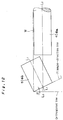
- Fig. 4 shows two views, i.e. a conceptual perspective view and a conceptual front view, of the rotary cam 5 as divided into the end rotary cam section 5 1 on which the flange 11 of the work W is placed and the main rotary cam section 5 2 on which the other portion is placed, both having the same single axis of rotation.
- the end rotary cam section 5 1 is formed with a wall surface 61 along the flange direction line of the work W.
- the flange 11 is placed on the end rotary cam section 5 1 along this flange-direction line.
- the end rotary cam section 5 1 has an axial end face opposed to an axial end face of the main rotary cam section 5 2 formed with a slant surface 62 including a slant line across the flange-direction line.
- the slant surface 62 of the end rotary cam section 5 1 is faced by an end face of the main rotary cam section 5 2 which is formed in two surfaces, i.e. a slant surface 63 (a portion above the rotation axis in Fig. 3) including a slant line similar to the one in the slant surface 62, and an orthogonal surface 64 (a portion below the axis in Fig. 3).
- a slant surface 63 (a portion above the rotation axis in Fig. 3) including a slant line similar to the one in the slant surface 62, and an orthogonal surface 64 (a portion below the axis in Fig. 3).
- the end rotary cam section 5 1 is rotated by a transmission pin 65 projecting out of the end face of the main rotary cam section 5 2 .
- the pin 65 is radially spaced from the axis of rotation.
- Fig. 3 and the lower illustration in Fig. 4 show a state of intrusion forming.
- the main rotary cam section 5 2 is pivoted by the cylinder 51 back in the retracting direction A.
- the wall surface 61 of the end rotary cam section 5 1 would deform the flange 11 of the work W.
- the end rotary cam section 5 1 is held unmoved in a certain range of the pivoting movement of the main rotary cam section 5 2 .
- the main rotary cam section 5 2 is pivoted but the end rotary cam section 5 1 is not.
- the end rotary cam section 5 1 is held unmoved by a long arcuate groove 66 provided in the slant surface 62 of the end rotary cam section 5 1 .
- an arm 67 is provided on the end portion of the supporting shaft 52.
- the arm 67 and the lower die half 1 are provided with hook bolts 68, 69 respectively for respectively hooking to the ends of a tension spring 70 extending between the hook bolts 68, 69.
- This tension spring 70 retains the end rotary cam section 5 1 at the state of intrusion forming via the arm 67.
- the arm 67 contacts with and thereby stops on a stopper 71 protruding out from the lower die half 1.
- the end rotary cam section 5 1 is pulled in the direction opposite to the retracting rotation direction of the rotary cam by the tension spring 70 for a certain initial period of the retraction.
- the driving force from the cylinder 51 is started to be transmitted to the end rotary cam section 5 1 and an axial movement of the end rotary cam section 5 1 is initiated, so that the flange 11 of the work W does not interfere with the wall 61 of the end rotary cam section 5 1 , thereby allowing the work W after the intrusion formation to be taken out.
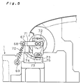
- a downwardly extending hanging plate 72 is interposed between the arm 67 and an end face of the supporting shaft 52.
- a cam follower 73 is, preferably rotatably, provided at a lower end of the hanging plate 72.
- the lower die half 1 is provided with a cam block 75 formed with a cam groove 74 for guiding the cam follower 73.
- the end rotary cam section 5 1 is pulled by the tension spring 70 in the direction opposite to the retracting rotation direction of the rotary cam and therefore is held unmoved relative to the main rotary cam section 5 2 .
- the cam follower 73 is at a right side as viewed in the figure 5.
- the transmission pin 65 reaches an end of the arcuate groove 66, whereupon the driving force from the cylinder 51 starts to be transmitted to the end rotary cam section 5 1 against the urge from the tension spring 70.
- the downwardly hanging plate 72 connected with the end rotary cam section 5 1 is rotated and together therewith the cam follower 73 moves in the cam groove 74 of the cam block attached to the lower die half.
- the cam groove 74 is formed to extend in a direction so as to come closer to the main rotary cam section 5 2 at an upper point.
- the cam follower 73 and the end rotary cam section 5 1 to which it is attached are moved axially closer to the main rotary cam section 5 2 .
- the slant surface 62 of the end rotary cam section 5 1 and the slant surface 63 of the main rotary cam section 5 2 are arranged so that they do not interfere with each other but to allow the end rotary cam section 5 1 to move axially toward the main rotary cam section 52.
- the end rotary cam section 5 1 is held unmoved relative to the main rotary cam section 5 2 by the tension spring 70.
- the driving force from the cylinder 51 starts to be transmitted to the end rotary cam section 5 1 via the main rotary cam section 5 2 and rotates and axially moves the end rotary cam section 5 1 .
- the end rotary cam section 5 1 is axially moved in that the cam follower 73 is guided along the cam groove 74 extending axially toward the main rotary cam section 5 2 .
- the axial movement of the end rotary cam section avoids that the flange of the work W interferes with and is deformed by the wall surface 61 of the end rotary cam section 5 1 .
- a left-end rotary cam section 81 and a right-end rotary cam section 82 can be arranged at the opposite axial ends of the main rotary cam section 83 and moved toward the main rotary cam section 83 in a manner similar to the above described embodiment.
- the retaining period and the axial movement period of the end rotary cam section has been described above to take place in immediate sequence, this is not a prerequisite.
- the period of retaining and the period of axial movement during the retracting pivoting movement can be chosen as desired by appropriately positioning the above mentioned elements comprising cam follower, cam groove, arcuate groove, transmission pin and angled axial end surfaces of adjacent end faces of the respective rotary cam sections.
- the negative angle forming die of the present invention ist is possible to protect the work (W) from potential damage caused by interference of the rotary cam (5) with portions of the work (W) protruding in a direction extending across the rotation axis during retraction of the rotary cam (5) after the intrusion forming while the die is simplified in structure and can be manufacturing at reduced cost, and at the same time provides improved accuracy so that a high quality product can be manufactured with this die.
Abstract
Description
Claims (3)
- A negative-angle forming die comprising:wherein the rotary cam (5) is divided into at least an end rotary cam section (51) and a main rotary cam section (52), both of the divided rotary cam sections (51,52) being disposed on the same pivoting axis (L), and the end rotary cam section (51) being provided with means for restricting the end rotary cam section (51) from pivoting for a predetermined period of the pivoting during retraction of the rotary cam after the forming operation, and for axially moving the end rotary cam section (51) relative to the main rotary cam section (52) for a predetermined period of the pivoting during retraction of the rotary cam after the forming operation, thereby protecting the work (W) from potential damage caused by interference of the rotary cam (5) with portions of the work (W) protruding in a direction extending across the rotation axis during retraction of the rotary cam (5).a lower die half (1) having a supporting portion (2) for placing a sheet metal work (W) thereon;an upper die half (3) adapted to be lowered downward onto the lower die half (1) for forming the sheet metal work;a rotary cam (5) including an intrusion forming portion and being rotatably supported in the lower die half (1);a slide cam (8) including an intrusion forming portion and slidably opposed to the rotary cam (5), wherein the sheet metal work (W) placed on the supporting portion (2) of the lower die half (1) is adapted to be formed by the cooperation of the intrusion forming portions of the rotary cam (5) and of the slide cam (8); andan automatic retractor provided in the lower die half (1) for pivoting the rotary cam (5) back to a position where the work (W) can be taken out of the lower die half (1) after a forming operation;
- The negative-angle forming die according to claim 1, wherein the means for restricting the end rotary cam section (51) from pivoting for a predetermined period of the retraction and effecting the axial movement thereof relative to the main rotary cam section (52) comprise:a slant end face (62) formed on the end rotary cam section (51) facing the main rotary cam section (52), the main rotary cam section (52) having an end face including half of the face formed as a slant face (63) for contact with the slant end face (62) of the end rotary cam section (51) and the other half of the face formed as a face (64) orthogonal to the axis of rotation,a transmission pin (65) provided on the end face of the main rotary cam section (52) facing the end rotary cam section (51) at a position radially spaced from the axis of rotation,a long arcuate groove (66) for receiving the transmission pin (65) formed in the slant surface (62) of the end rotary cam section (51),an urging member (67,70) for keeping the end rotary cam section (51) in an attitude of the intrusion formation provided between the end rotary cam section (51) and the lower die half (1), anda cam follower (73) connected with the end rotary cam section (51) and guided by a cam groove (74) provided at the lower die half (1) for moving the end rotary cam section (51) toward the the main rotary cam section (52) after the predetermined amount of pivoting of the main rotary cam section (52).
- The negative-angle forming die according to claim 1 or 2, wherein an intrusion forming portion is formed in the lower die half (1) at an edge portion near the supporting portion (2) inward of a downward stroke line of the upper die half (3).
Applications Claiming Priority (2)
| Application Number | Priority Date | Filing Date | Title |
|---|---|---|---|
| JP2001079971A JP3492642B2 (en) | 2001-03-21 | 2001-03-21 | Rotating cam moving device of negative angle forming die |
| JP2001007991 | 2001-03-21 |
Publications (3)
| Publication Number | Publication Date |
|---|---|
| EP1243355A2 true EP1243355A2 (en) | 2002-09-25 |
| EP1243355A3 EP1243355A3 (en) | 2003-10-08 |
| EP1243355B1 EP1243355B1 (en) | 2006-01-04 |
Family
ID=18936333
Family Applications (1)
| Application Number | Title | Priority Date | Filing Date |
|---|---|---|---|
| EP01114221A Expired - Lifetime EP1243355B1 (en) | 2001-03-21 | 2001-06-12 | Negative-angle forming die |
Country Status (10)
| Country | Link |
|---|---|
| US (1) | US6539766B2 (en) |
| EP (1) | EP1243355B1 (en) |
| JP (1) | JP3492642B2 (en) |
| KR (1) | KR20020075174A (en) |
| CN (1) | CN1375364A (en) |
| BR (1) | BR0102969A (en) |
| CA (1) | CA2346232A1 (en) |
| DE (1) | DE60116412T2 (en) |
| ES (1) | ES2255525T3 (en) |
| TW (1) | TW494024B (en) |
Cited By (1)
| Publication number | Priority date | Publication date | Assignee | Title |
|---|---|---|---|---|
| EP2320102A3 (en) * | 2009-10-16 | 2014-01-22 | Yourbusiness Co., Ltd. | Rotating structure for rotary forming die |
Families Citing this family (16)
| Publication number | Priority date | Publication date | Assignee | Title |
|---|---|---|---|---|
| JP2004042109A (en) * | 2002-07-12 | 2004-02-12 | Umix Co Ltd | Apparatus for moving rotary cam in negative angle shaping die |
| US7258030B2 (en) * | 2003-01-21 | 2007-08-21 | Syron Engineering & Manufacturing, Llc | Failsafe element for rotary cam unit used in a flanged die |
| DE10340509A1 (en) * | 2003-09-03 | 2005-03-31 | Bayerische Motoren Werke Ag | Wedge drive tool with mutually adjustable elements for cutting a sheet metal workpiece without cutting in a press |
| US7523634B2 (en) * | 2004-08-24 | 2009-04-28 | Helical Cam, Llc. | Forming die having filler cam assembly |
| US7431502B2 (en) * | 2004-09-15 | 2008-10-07 | Anchor Lamina America, Inc. | Universal cam slide |
| TWM275895U (en) * | 2005-01-12 | 2005-09-21 | Shu-Ching Lin | Bending structure for stainless steel plate |
| US8171821B2 (en) | 2006-09-28 | 2012-05-08 | Helical Cam, Llc | Corner cam assembly |
| US7624615B2 (en) * | 2006-10-27 | 2009-12-01 | Chrysler Group Llc | Wedge activated rotating filler cam |
| US7735907B2 (en) * | 2007-12-27 | 2010-06-15 | Toyota Motor Engineering & Manufacturing North America, Inc. | Pillar for motor vehicle and tool for making the same |
| US8516874B2 (en) * | 2007-12-27 | 2013-08-27 | Toyota Motor Engineering & Manufacturing North America, Inc. | Pillar for motor vehicle and tool for making the same |
| US8033155B2 (en) * | 2008-07-30 | 2011-10-11 | Hirotec Corporation | Press die set for forming flange and flange forming method |
| DE102010051790A1 (en) * | 2010-11-18 | 2012-05-24 | GM Global Technology Operations LLC | Bending device with rotary tool |
| WO2012075363A1 (en) * | 2010-12-02 | 2012-06-07 | Norgren Automation Solutions, Inc. | Bending die with radial cam unit |
| US8739596B2 (en) * | 2011-09-26 | 2014-06-03 | Chrysler Group Llc | Wedge activated rotating filler cam utilizing a saddle for rotation |
| CN102974693B (en) * | 2012-09-29 | 2016-05-04 | 苏州鑫捷顺五金机电有限公司 | A kind of negative angle bending die tool |
| KR101550619B1 (en) * | 2013-12-30 | 2015-09-07 | 현대자동차 주식회사 | Press device |
Citations (5)
| Publication number | Priority date | Publication date | Assignee | Title |
|---|---|---|---|---|
| EP0427886A1 (en) * | 1989-11-16 | 1991-05-22 | Uemura Metal Industries Co., Ltd. | Die for negative angle forming |
| EP0699489A1 (en) * | 1993-06-25 | 1996-03-06 | UMIX Co., Ltd. | Method of forming thin plate and its forming die |
| EP0857525A1 (en) * | 1997-02-05 | 1998-08-12 | Umix Co., Ltd. | Thin sheet forming dies |
| EP0858847A1 (en) * | 1997-02-05 | 1998-08-19 | Umix Co., Ltd. | Thin sheet forming dies |
| EP1044739A2 (en) * | 1999-04-15 | 2000-10-18 | Umix Co., Ltd. | Negative angular forming dies and pressing apparatus thereof |
Family Cites Families (1)
| Publication number | Priority date | Publication date | Assignee | Title |
|---|---|---|---|---|
| JP3370628B2 (en) * | 1999-11-15 | 2003-01-27 | ユミックス株式会社 | Negative angle mold |
-
2001
- 2001-03-21 JP JP2001079971A patent/JP3492642B2/en not_active Expired - Fee Related
- 2001-05-03 TW TW090110583A patent/TW494024B/en not_active IP Right Cessation
- 2001-05-04 CA CA002346232A patent/CA2346232A1/en not_active Abandoned
- 2001-05-21 KR KR1020010027558A patent/KR20020075174A/en not_active Application Discontinuation
- 2001-06-04 BR BR0102969-0A patent/BR0102969A/en not_active IP Right Cessation
- 2001-06-06 CN CN01121218A patent/CN1375364A/en active Pending
- 2001-06-12 DE DE60116412T patent/DE60116412T2/en not_active Expired - Fee Related
- 2001-06-12 ES ES01114221T patent/ES2255525T3/en not_active Expired - Lifetime
- 2001-06-12 EP EP01114221A patent/EP1243355B1/en not_active Expired - Lifetime
- 2001-06-14 US US09/880,021 patent/US6539766B2/en not_active Expired - Fee Related
Patent Citations (5)
| Publication number | Priority date | Publication date | Assignee | Title |
|---|---|---|---|---|
| EP0427886A1 (en) * | 1989-11-16 | 1991-05-22 | Uemura Metal Industries Co., Ltd. | Die for negative angle forming |
| EP0699489A1 (en) * | 1993-06-25 | 1996-03-06 | UMIX Co., Ltd. | Method of forming thin plate and its forming die |
| EP0857525A1 (en) * | 1997-02-05 | 1998-08-12 | Umix Co., Ltd. | Thin sheet forming dies |
| EP0858847A1 (en) * | 1997-02-05 | 1998-08-19 | Umix Co., Ltd. | Thin sheet forming dies |
| EP1044739A2 (en) * | 1999-04-15 | 2000-10-18 | Umix Co., Ltd. | Negative angular forming dies and pressing apparatus thereof |
Cited By (1)
| Publication number | Priority date | Publication date | Assignee | Title |
|---|---|---|---|---|
| EP2320102A3 (en) * | 2009-10-16 | 2014-01-22 | Yourbusiness Co., Ltd. | Rotating structure for rotary forming die |
Also Published As
| Publication number | Publication date |
|---|---|
| JP3492642B2 (en) | 2004-02-03 |
| EP1243355B1 (en) | 2006-01-04 |
| TW494024B (en) | 2002-07-11 |
| CA2346232A1 (en) | 2002-09-21 |
| ES2255525T3 (en) | 2006-07-01 |
| CN1375364A (en) | 2002-10-23 |
| BR0102969A (en) | 2002-12-03 |
| DE60116412T2 (en) | 2006-08-24 |
| US6539766B2 (en) | 2003-04-01 |
| US20020124620A1 (en) | 2002-09-12 |
| JP2002273524A (en) | 2002-09-25 |
| DE60116412D1 (en) | 2006-03-30 |
| KR20020075174A (en) | 2002-10-04 |
| EP1243355A3 (en) | 2003-10-08 |
Similar Documents
| Publication | Publication Date | Title |
|---|---|---|
| EP1243355B1 (en) | Negative-angle forming die | |
| US6523386B2 (en) | Negative-angle forming die | |
| US20080098792A1 (en) | Wedge activated rotating filler cam | |
| EP1238722B1 (en) | Negative-angle forming die | |
| US5746082A (en) | Thin sheet forming die assembly including lower die cylindrical member having varied diameters | |
| US6612146B2 (en) | Hemming machine with movable die cartridges | |
| US20060179910A1 (en) | Pre-hemming apparatus | |
| EP0745009A1 (en) | Improved hemming machine | |
| US5495742A (en) | Press for hemming panels | |
| EP1238720A2 (en) | Negative-angle forming die | |
| KR102234943B1 (en) | Horizontal banding device | |
| KR20000011868A (en) | Machine for punching and bending metal sheets | |
| KR100313722B1 (en) | Chucking hemming machine | |
| US20080083258A1 (en) | Tilting System for a Flanging Device | |
| KR102204663B1 (en) | Rolling type bending press device | |
| US11253902B2 (en) | Hemming apparatus | |
| US7204118B2 (en) | Hemming tool die assembly | |
| US20230069244A1 (en) | Press brake with rotary tool assembly | |
| US7111538B2 (en) | Double acting cam die | |
| JP2000233232A (en) | Press forming device for flange | |
| KR100498875B1 (en) | Hemming equipment | |
| EP1258301A2 (en) | Hemming machine with movable die cartridges | |
| EP1477246B1 (en) | Metal sheet clinching unit | |
| JPH04258316A (en) | Bending press die | |
| JPH0679352A (en) | U-shaped press bending device |
Legal Events
| Date | Code | Title | Description |
|---|---|---|---|
| PUAI | Public reference made under article 153(3) epc to a published international application that has entered the european phase |
Free format text: ORIGINAL CODE: 0009012 |
|
| AK | Designated contracting states |
Kind code of ref document: A2 Designated state(s): AT BE CH CY DE DK ES FI FR GB GR IE IT LI LU MC NL PT SE TR |
|
| AX | Request for extension of the european patent |
Free format text: AL;LT;LV;MK;RO;SI |
|
| PUAL | Search report despatched |
Free format text: ORIGINAL CODE: 0009013 |
|
| AK | Designated contracting states |
Kind code of ref document: A3 Designated state(s): AT BE CH CY DE DK ES FI FR GB GR IE IT LI LU MC NL PT SE TR |
|
| AX | Request for extension of the european patent |
Extension state: AL LT LV MK RO SI |
|
| RIC1 | Information provided on ipc code assigned before grant |
Ipc: 7B 21D 22/08 B Ipc: 7B 21D 22/06 B Ipc: 7B 21D 19/08 B Ipc: 7B 21D 5/04 B Ipc: 7B 21D 37/08 A |
|
| 17P | Request for examination filed |
Effective date: 20040407 |
|
| AKX | Designation fees paid |
Designated state(s): DE ES FR GB IT SE |
|
| GRAP | Despatch of communication of intention to grant a patent |
Free format text: ORIGINAL CODE: EPIDOSNIGR1 |
|
| GRAS | Grant fee paid |
Free format text: ORIGINAL CODE: EPIDOSNIGR3 |
|
| GRAA | (expected) grant |
Free format text: ORIGINAL CODE: 0009210 |
|
| AK | Designated contracting states |
Kind code of ref document: B1 Designated state(s): DE ES FR GB IT SE |
|
| REG | Reference to a national code |
Ref country code: GB Ref legal event code: FG4D |
|
| REF | Corresponds to: |
Ref document number: 60116412 Country of ref document: DE Date of ref document: 20060330 Kind code of ref document: P |
|
| REG | Reference to a national code |
Ref country code: SE Ref legal event code: TRGR |
|
| REG | Reference to a national code |
Ref country code: ES Ref legal event code: FG2A Ref document number: 2255525 Country of ref document: ES Kind code of ref document: T3 |
|
| ET | Fr: translation filed | ||
| PLBE | No opposition filed within time limit |
Free format text: ORIGINAL CODE: 0009261 |
|
| STAA | Information on the status of an ep patent application or granted ep patent |
Free format text: STATUS: NO OPPOSITION FILED WITHIN TIME LIMIT |
|
| 26N | No opposition filed |
Effective date: 20061005 |
|
| PGFP | Annual fee paid to national office [announced via postgrant information from national office to epo] |
Ref country code: ES Payment date: 20070620 Year of fee payment: 7 |
|
| PGFP | Annual fee paid to national office [announced via postgrant information from national office to epo] |
Ref country code: SE Payment date: 20070626 Year of fee payment: 7 |
|
| PGFP | Annual fee paid to national office [announced via postgrant information from national office to epo] |
Ref country code: DE Payment date: 20070830 Year of fee payment: 7 |
|
| PGFP | Annual fee paid to national office [announced via postgrant information from national office to epo] |
Ref country code: GB Payment date: 20070618 Year of fee payment: 7 |
|
| PGFP | Annual fee paid to national office [announced via postgrant information from national office to epo] |
Ref country code: IT Payment date: 20070628 Year of fee payment: 7 |
|
| PGFP | Annual fee paid to national office [announced via postgrant information from national office to epo] |
Ref country code: FR Payment date: 20070619 Year of fee payment: 7 |
|
| EUG | Se: european patent has lapsed | ||
| GBPC | Gb: european patent ceased through non-payment of renewal fee |
Effective date: 20080612 |
|
| REG | Reference to a national code |
Ref country code: FR Ref legal event code: ST Effective date: 20090228 |
|
| PG25 | Lapsed in a contracting state [announced via postgrant information from national office to epo] |
Ref country code: DE Free format text: LAPSE BECAUSE OF NON-PAYMENT OF DUE FEES Effective date: 20090101 |
|
| PG25 | Lapsed in a contracting state [announced via postgrant information from national office to epo] |
Ref country code: GB Free format text: LAPSE BECAUSE OF NON-PAYMENT OF DUE FEES Effective date: 20080612 |
|
| REG | Reference to a national code |
Ref country code: ES Ref legal event code: FD2A Effective date: 20080613 |
|
| PG25 | Lapsed in a contracting state [announced via postgrant information from national office to epo] |
Ref country code: FR Free format text: LAPSE BECAUSE OF NON-PAYMENT OF DUE FEES Effective date: 20080630 Ref country code: IT Free format text: LAPSE BECAUSE OF NON-PAYMENT OF DUE FEES Effective date: 20080612 |
|
| PG25 | Lapsed in a contracting state [announced via postgrant information from national office to epo] |
Ref country code: ES Free format text: LAPSE BECAUSE OF NON-PAYMENT OF DUE FEES Effective date: 20080613 |
|
| PG25 | Lapsed in a contracting state [announced via postgrant information from national office to epo] |
Ref country code: SE Free format text: LAPSE BECAUSE OF NON-PAYMENT OF DUE FEES Effective date: 20080613 |