EP1243342B9 - Universal-Abgabesystem zum luftunterstütztem Schmelzspinnen von Flüssigkeitsfäden - Google Patents
Universal-Abgabesystem zum luftunterstütztem Schmelzspinnen von Flüssigkeitsfäden Download PDFInfo
- Publication number
- EP1243342B9 EP1243342B9 EP02005595A EP02005595A EP1243342B9 EP 1243342 B9 EP1243342 B9 EP 1243342B9 EP 02005595 A EP02005595 A EP 02005595A EP 02005595 A EP02005595 A EP 02005595A EP 1243342 B9 EP1243342 B9 EP 1243342B9
- Authority
- EP
- European Patent Office
- Prior art keywords
- nozzle
- lever
- mounting surface
- supply passage
- clamping
- Prior art date
- Legal status (The legal status is an assumption and is not a legal conclusion. Google has not performed a legal analysis and makes no representation as to the accuracy of the status listed.)
- Expired - Lifetime
Links
Images


Classifications
-
- B—PERFORMING OPERATIONS; TRANSPORTING
- B05—SPRAYING OR ATOMISING IN GENERAL; APPLYING FLUENT MATERIALS TO SURFACES, IN GENERAL
- B05C—APPARATUS FOR APPLYING FLUENT MATERIALS TO SURFACES, IN GENERAL
- B05C5/00—Apparatus in which liquid or other fluent material is projected, poured or allowed to flow on to the surface of the work
- B05C5/02—Apparatus in which liquid or other fluent material is projected, poured or allowed to flow on to the surface of the work the liquid or other fluent material being discharged through an outlet orifice by pressure, e.g. from an outlet device in contact or almost in contact, with the work
- B05C5/027—Coating heads with several outlets, e.g. aligned transversally to the moving direction of a web to be coated
-
- B—PERFORMING OPERATIONS; TRANSPORTING
- B05—SPRAYING OR ATOMISING IN GENERAL; APPLYING FLUENT MATERIALS TO SURFACES, IN GENERAL
- B05B—SPRAYING APPARATUS; ATOMISING APPARATUS; NOZZLES
- B05B15/00—Details of spraying plant or spraying apparatus not otherwise provided for; Accessories
- B05B15/60—Arrangements for mounting, supporting or holding spraying apparatus
- B05B15/65—Mounting arrangements for fluid connection of the spraying apparatus or its outlets to flow conduits
-
- B—PERFORMING OPERATIONS; TRANSPORTING
- B05—SPRAYING OR ATOMISING IN GENERAL; APPLYING FLUENT MATERIALS TO SURFACES, IN GENERAL
- B05B—SPRAYING APPARATUS; ATOMISING APPARATUS; NOZZLES
- B05B7/00—Spraying apparatus for discharge of liquids or other fluent materials from two or more sources, e.g. of liquid and air, of powder and gas
- B05B7/02—Spray pistols; Apparatus for discharge
- B05B7/08—Spray pistols; Apparatus for discharge with separate outlet orifices, e.g. to form parallel jets, i.e. the axis of the jets being parallel, to form intersecting jets, i.e. the axis of the jets converging but not necessarily intersecting at a point
- B05B7/0807—Spray pistols; Apparatus for discharge with separate outlet orifices, e.g. to form parallel jets, i.e. the axis of the jets being parallel, to form intersecting jets, i.e. the axis of the jets converging but not necessarily intersecting at a point to form intersecting jets
- B05B7/0861—Spray pistols; Apparatus for discharge with separate outlet orifices, e.g. to form parallel jets, i.e. the axis of the jets being parallel, to form intersecting jets, i.e. the axis of the jets converging but not necessarily intersecting at a point to form intersecting jets with one single jet constituted by a liquid or a mixture containing a liquid and several gas jets
-
- B—PERFORMING OPERATIONS; TRANSPORTING
- B05—SPRAYING OR ATOMISING IN GENERAL; APPLYING FLUENT MATERIALS TO SURFACES, IN GENERAL
- B05C—APPARATUS FOR APPLYING FLUENT MATERIALS TO SURFACES, IN GENERAL
- B05C5/00—Apparatus in which liquid or other fluent material is projected, poured or allowed to flow on to the surface of the work
- B05C5/02—Apparatus in which liquid or other fluent material is projected, poured or allowed to flow on to the surface of the work the liquid or other fluent material being discharged through an outlet orifice by pressure, e.g. from an outlet device in contact or almost in contact, with the work
Definitions
- the present invention generally relates to dispensing systems for applying a liquid material and, more particularly, for dispensing a filament or filaments of liquid, such as hot melt adhesive, on a substrate.
- meltblowing systems may be used during the manufacture of products such as diapers, feminine hygiene products and the like.
- meltblowing systems include a source of liquid thermoplastic material, a source of pressurized process air, and a manifold for distributing the liquid material and process air.
- a plurality of modules or dispensing valves may be mounted to the manifold for receiving the liquid and process air and dispensing an elongated filament of the liquid material which is attenuated and drawn down by the air before being randomly applied onto the substrate.
- a meltblowing die tip or nozzle includes a plurality of liquid discharge orifices arranged in a row and a slot on each side of the row of liquid discharge orifices for dispensing the air.
- a slot instead of slots, it is also well known to use two rows of air discharge orifices parallel to the row of liquid discharge orifices.
- Controlled fiberization dispensing systems also use air assisted extrusion nozzles. However, the pressurized process air in these systems is used to swirl the extruded liquid filament.
- Conventional swirl nozzles or die tips typically have a central liquid discharge passage surrounded by a plurality of process air discharge passages.
- the liquid discharge passage is centrally located on a protrusion.
- a common configuration for the protrusion is conical or frustoconical with the liquid discharge passage opening at the apex.
- the process air discharge passages are typically disposed at the base of the protrusion.
- the process air discharge passages are usually arranged in a radially symmetric pattern about the central liquid discharge passage.
- the process air discharge passages are directed in a generally tangential manner relative to the liquid discharge orifice and are all angled in a clockwise or counterclockwise direction around the central liquid discharge passage.
- a bi-radial nozzle includes a wedge-shaped member having a pair of side surfaces converging to an apex.
- a liquid discharge passage extends along an axis through the wedge-shaped member and through the apex.
- the wedge-shaped member extends in a radially asymmetrical manner around the liquid discharge passage.
- Four process air discharge passages are positioned at the base of the wedge-shaped member. At least one process air discharge passage is positioned adjacent to each of the side surfaces and each of the process air discharge passages is angled in a compound manner generally toward the liquid discharge passage and offset from the axis of the liquid discharge passage.
- EP-A-093600 discloses an apparatus as described in the preamble of claims 1 and 9.
- Each dispensing valve may have to be unbolted from the manifold by unscrewing at least two bolts. The nozzle is then removed from the dispensing valve and another nozzle is mounted onto the valve. If necessary, the valve is reattached to the manifold. Consequently, such repair can increase the required shut down time for removal and replacement of valves and nozzles. Removal of the entire dispensing valve with the attached nozzle is generally a requirement when changing between applications (e.g., meltblowing to controlled fiberization).
- the present invention provides an apparatus for dispensing a filament of liquid which may or may not be assisted by pressurized process air.
- the apparatus comprises a housing having a liquid supply passage and a nozzle mounting surface which may be disposed within a recess of the housing.
- a nozzle includes an inlet side positioned adjacent the mounting surface and an outlet side having at least one liquid discharge orifice and, optionally, a plurality of process air discharge passages adjacent the liquid discharge orifice.
- the liquid discharge orifice and the process air discharge air passages are respectively in fluid communication with the liquid supply passage and the process air supply passage of the housing, if applicable.
- a nozzle ejecting lever is pivotally affixed to the housing and pivotally moves from a first position to a second position.
- the nozzle In the first position, the nozzle may be mounted adjacent the mounting surface as described above and, as the ejecting lever is moved to the second position, the nozzle is pried away from the mounting surface. This assists in removing nozzles which may be otherwise adhered to the housing due to thermoplastic liquid or other reasons.
- a clamping and ejecting lever such that a single lever may be used to clamp and lock a nozzle into place on the housing and also to eject the nozzle from the housing and the nozzle mounting surface.
- This lever may be pivotally attached to the housing such that one portion thereof is formed with one or more cam surfaces which engage one or more cam surfaces of the nozzle to clamp and lock the nozzle into place on the housing. Another portion of the lever may be used when the lever is rotated in an opposite direction to eject the nozzle.
- the nozzle and the housing each include mating portions which align the nozzle with respect to the housing.
- these portions take the form of one or more tabs on the nozzle and one or more aligned slots in the housing adjacent the nozzle mounting surface.
- the ejecting portion of the lever may engage the tab to provide the prying force necessary to eject the nozzle.
- the dispensing valve may include an upper air actuating portion having a diaphragm/piston arrangement for opening and closing the valve.
- This diaphragm may be housed in a chamber having upper and lower pressurized air supply ports.
- the upper chamber in this aspect, includes a further port which may or may not be plugged. When plugged, pressurized air in the upper chamber may be used to force the diaphragm and piston assembly downward to close the valve. When the plug is removed, any pressurized air introduced into this upper chamber is immediately exhausted, and a spring return mechanism takes over as the valve closing mechanism.
- a plurality of nozzles are provided in a liquid dispensing system in accordance with the invention, with each nozzle configured to discharge a different filament pattern.
- a first nozzle may be configured to dispense meltblown filaments while a second nozzle may be configured to dispense a swirl filament pattern.
- Each of the nozzles is constructed to be received in the recess such that the liquid discharge orifice or orifices of the nozzle and the process air discharge passages are respectively in fluid communication with the liquid supply passage and process air supply passage of the housing.
- Each nozzle is symmetrically configured such that the nozzle may be rotated 180° and still be mountable within the housing recess.
- the nozzle includes cam surfaces on opposite sidewall portions thereof which can each interchangeably engage the cam surface of the clamping lever or a cam surface formed on a wall of the recess.
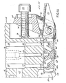
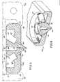
- Fig. 1 is a cross-sectional view of a dispensing system configured to hold different types of air assisted extrusion nozzles in accordance with the principles of the present invention for dispensing liquid filaments;
- thermoplastic liquid such as hot melt thermoplastic adhesives
- those of ordinary skill in the art will readily appreciate application of the present invention to dispensing of other materials and use other types of nozzles.
- a liquid dispensing system 10 for air assisted extrusion of liquid filaments is depicted as including a dispensing valve or die module 12 and a manifold 14. It will be appreciated that one or more of the die modules 12 may be mounted in side-by-side relationship to the manifold 14 that distributes liquid material and pressurized air to each of the die modules 12.
- Each dispensing valve or die module 12 includes a pneumatic valve mechanism 16 in a housing 18. The pneumatic valve mechanism 16 is in fluid communication with the manifold 14 to receive the liquid material and to a liquid material flow passage 20 in the housing 18. The valve may alternatively be electrically actuated for controlling flow of the liquid material through the dispensing valve 12.
- the housing 18 includes an air supply passage 22 adapted to receive the pressurized air from the manifold 14 and two air flow passages 24, 26 that are parallel to and on each side of the liquid material flow passage 20.
- the pair of air flow passages 24, 26 allows mounting of different types of nozzles, but does result in different air flow path distances from the air supply passage 22.
- an annular air chamber 28 in the housing 18 is in fluid communication with both the air supply passage 22 and the air flow passages 24, 26 for balancing air flow.
- the different types of nozzles 32a, 32b, 32c benefit from the even distribution of air flow.
- these different types of nozzles 32a, 32b, 32c include meltblowing, controlled fiberization (hereinafter "swirl") and nozzles currently manufactured and sold under the trademark SUMMITTM by Nordson Corporation, the assignee of the present invention.
- the SUMMITTM nozzles are hereinafter referred to as bi-radial nozzles.
- Portions of the dispensing valve 12 form a nozzle assembly 30 for selectively and expeditiously mounting various types of air assisted extrusion nozzles 32a to the housing 18.
- the nozzle assembly 30 includes a clamping structure that allows access for removing and installing a nozzle 32a to the dispensing valve 12 from the front side opposite the manifold 14.
- the nozzle 32a is frictionally held in contact with a nozzle mounting surface 36 by the opposition of a fixed member or wall 38 of the housing 18 and a positioning lever 40, which creates a positioning and temporary clamping force parallel to the nozzle mounting surface 36.
- the temporary support avoids prolonged manual holding of the nozzle 32a, which beneficially reduces the amount of time that a user must be in contact with the typically hot surface of the dispensing valve 12 as well as making installation more convenient.
- This frictional force from the positioning lever 40 advantageously supports the nozzle 32a while a pivoting clamping lever 42 locks the nozzle 32a to the nozzle mounting surface 36.
- a socket head cap screw 44 is threaded inward against housing 18, outwardly pivoting an upper portion 46 of the clamping lever 42 about a pivot pin 48, thereby pivoting a lower portion 50 of the clamping lever 42 under the nozzle 32a.
- a cam surface 52 of the lower portion 50 makes inward and upward contact to a forward cam surface 54 of the nozzle 32a, with a rearward cam surface 56 of the nozzle 32a similarly supported by a cam surface 58 of the fixed member or wall 38.
- each nozzle 32a, 32b, 32c may be selected for mounting to the nozzle assembly 30.
- the air inputs 60, 62 and liquid input 64 of each nozzle 32a, 32b, 32c are registered to be in liquid communication respectively with the liquid material flow passage 20 and air flow passages 24, 26 of the housing 18. Pressurized process air flow is diffused by one or more air troughs 66 that provide a tortuous air flow path through nozzle 32a and slow down the air flow velocity exiting process air discharge passages 68.
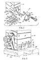
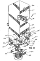
- the dispensing valve 12 is shown with the nozzle 32a and nozzle assembly 30 disassembled to illustrate additional features.
- the positioning lever 40 and clamping lever 42 are pivotally affixed to the housing 18 with the same pivot pin 48.
- the positioning lever 40 resides within a slot 72 in the clamping lever 42 that allows the positioning lever 40 to pivot upward to an ejection position when the pivoting lever is in an unlocked or loosened state.
- the cap screw 44 is retained within a threaded hole 74 in the clamping lever 42 by a snap ring 76.
- An upper surface 78 of the nozzle 32a includes a symmetric pattern of air inlets 60, 62 and liquid inlet 64 so that the nozzle 32a may be inserted in one of two orientations with one being 180 degrees rotated from the other.
- the upper surface 78 also includes symmetrically placed alignment recesses 86, 88 registered to receive an alignment pin 90 affixed to the nozzle mounting surface 36 (shown in Figs. 1 and 1A ), that assist in positioning the upper surface 78 relative to the nozzle mounting surface 36.
- the nozzle assembly 30 is shown with a bi-radial nozzle 32a mounted, as one type of air assisted extrusion.
- a detailed description of the bi-radial nozzle 32a is disclosed in co-pending U.S. Serial No. 09/571,703 , entitled "Module And Nozzle For Dispensing Controlled Patterns Of Liquid Material” and assigned to the common assignee, the disclosure of which is hereby incorporated herein by reference in its entirety.
- a meltblowing nozzle 32b and a swirl nozzle 32c are shaped similarly to the bi-radial nozzle 32a to be alternatively received in a recess 91 of the housing 18.
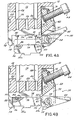
- FIG. 4A-4C use of the positioning lever 40 to assist in mounting and ejecting a nozzle 32a is illustrated with the clamping lever 42 adjusted to the unlocked position by outwardly adjusting the cap screw 44.
- the cam surface 52 of the clamping lever 42 does not impede an uninstalled nozzle 32a moved upward into proximity to the nozzle mounting surface 36, as depicted by the phantom lines.
- the rearward alignment recess 86 in the nozzle has sufficient dimensions to register to the alignment pin 90 with the nozzle shifted slightly forward to clear the fixed member or wall 38 which provides a rear boundary for recess 91.
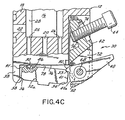
- a cam surface 40a is brought into frictional contact with the forward surface 41 of the nozzle 32a. This urges the rearward cam surface 56 into engagement with cam surface 58 of the fixed member or wall 38 thereby forcing nozzle 32a against the nozzle mounting surface 36. This temporarily aligns and clamps nozzle 32a within recess 91.
- the clamping lever 42 may be moved to the locked position by tightening fastener 44 (shown best in Fig. 1A ) for the period of use of the dispensing valve 12. This urges cam surface 52 against cam surface 54 thereby urging nozzle 32a upwardly into a clamped, sealing engagement against mounting surface 36.
- the clamping lever 42 is moved to the unlocked position as depicted. Then the positioning lever 40 is used as an ejection lever and is pivoted upward toward the ejection position. As the positioning lever 40 pivots upward, the projection 92 bears downward upon an upper cam surface 55 of the nozzle 32a for ejecting the nozzle 32a. A prying force thus applied by the positioning lever 40 on the nozzle 32a overcomes adhesion of accumulated liquid material during use.
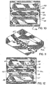
- Figs. 5-12 illustrate the three illustrative types of air assisted extrusion nozzles 32a, 32b, 32c adapted for being universally mounted to the dispensing valve 12.
- the controlled fiberization nozzle 32c has a circular air trough 94 that encompasses a central liquid input 96.
- Each of the air jets 98 receives pressurized air from the two air flow passages 24, 26 of the housing 18 after being diffused and slowed down in the circular air trough 94 so that none of the air jets 98 directly receives the pressurized air. Consequently, the air flow is more uniform for all air jets 98, as arrayed about a liquid orifice 100 that receives liquid material from the central liquid input 96.
- the meltblowing nozzle 32b depicted in Fig. 2 is shown having a row of orifices 102 flanked by rows of air jets 104. Balancing the air flow to these air jets 104 and providing consistent liquid flow to the orifices 102 is provided as shown in Fig. 10 .
- the upper surface 78 of the nozzle 32b includes a central elongate slot 106 for communicating the liquid material from the liquid material flow passage 20 of the housing 18 to the length of the row of orifices 102.
- Two elongate air troughs 108, 110 diffuse and slow down the air flow from each air flow passage 24, 26 respectively to the rows of air jets 104.
- the bi-radial nozzle 32a includes an elongate central slot 112 for providing liquid material to a row of orifices 70 and two elongate air troughs 66 to diffuse and slow down the air flow from each air flow passage 24, 26 respectively to the rows of air jets 68 nonradially positioned about the orifices 70.
- a nozzle assembly 30 for a dispensing valve 12 of a liquid dispensing system 10 is readily reconfigurable for various types of air assisted extrusion nozzles 32a, 32b, 32c without having to disassemble the dispensing valve 12 from the manifold 14 or having to remove multiple fasteners.
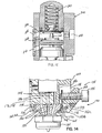
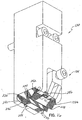
- Fig. 13 illustrates an alternative dispensing valve or die module 120 comprised of a valve body 122 which may be fastenable to a suitable support, such as a liquid and air supply manifold (not shown), by respective fasteners 124 which may be engaged with a tool at the front side of valve body 122.
- a suitable support such as a liquid and air supply manifold (not shown)
- fasteners 124 which may be engaged with a tool at the front side of valve body 122.
- a nozzle assembly 130 at the lower end of valve body 122 includes a nozzle 132a and a clamping and ejecting assembly 134 which is pivotally movable in the direction of arrow 136 about a pivot pin 138 affixed to a lower part 140 of valve body 122.
- assembly 134 includes a lever 142 having two clamping members 142a, 142b.
- this lever 142 may be used to clamp nozzle 132a into place by tightening bolt 144 against a surface 146 ( Fig. 14 ) within a recess 148 of valve body 122.
- Nozzle 132a is insertable within a recess 152 of valve body 122.
- suitable liquid and air supply passages are provided in valve body 122 for communicating with like passages in nozzle 132a.
- a passage 154 is provided for supplying liquid to nozzle 132a and passages 156 (two out of four shown) may be provided for directing process air into nozzle 132a. It will be understood by those of ordinary skill that passages 154 and 156 may take other forms and shapes, such as slot-like shapes.
- a cam surface 160 is formed in recess 152 and a mating cam surface 162 is formed on nozzle 132a.
- a cam surface 164 is formed on nozzle 132a and this cam surface 164 engages with respective cam surfaces 166, 168 on clamp members 142a, 142b.
- Tabs 170, 172 on opposite sides of nozzle 132a register within respective slots 173, 174 in lever 142 and valve body 122. As shown in Fig.
- liquid supply passage 154 communicates with liquid discharge passage 180 and process air passages 156 communicate with process air discharge passages 182 of nozzle 132a.
- liquid, such as hot melt adhesive, and process air are discharged through a portion 184 of nozzle 132a which may, as in this example, be a nozzle portion for emitting a swirled bead of adhesive.
- a nozzle for extruding a bead or filament of liquid without the assistance of process air may be used.
- nozzle 132a is inserted into recess 152 by loosening bolt 144 to such an extent that lever 142 can partially rotate counterclockwise as viewed in Fig. 14 .
- This allows the insertion of nozzle 132a with tabs 170, 172 traveling through respective slots 174, 173.
- bolt 144 is tightened against surface 146.
- This rotates lever clockwise and urges cam surfaces 166, 168 against cam surface 164 and further urges cam surfaces 160, 162 together to clamp respective nozzle and housing mounting surfaces 176, 178 together.
- bolt 144 is loosened sufficiently to allow partial rotation of lever 142 in a counterclockwise direction as viewed in Fig. 14 .
- This urges surface portion 142c of lever 142 against tab 172 to pry surfaces 176, 178 away from each other and eject nozzle 132a.
- Fig. 15 illustrates an upper actuating portion 200 of dispensing valve 120 including a reciprocating piston assembly 202 having a shaft or rod 204 and a piston or diaphragm member 206.
- a spring return mechanism 210 bears against a top of the shaft or rod 204 to hold the rod 204 and, therefore, the valve 120 in a normally closed position.
- An air port 212 is provided for allowing pressurized air to be introduced beneath the piston or diaphragm 206 to lift the shaft or rod 204 and therefore open the valve 120.
- a second port 214 is provided to communicate with a chamber 216 above the piston or diaphragm 206 to allow the introduction of pressurized air above diaphragm 206 in an "air-over-air" arrangement.
- another port 218 is provided in valve body 122 communicating with the upper chamber 216.
- This port 218 may receive a threaded plug 220 as shown in Fig. 13 .
- any pressurized air which is introduced through the upper supply port 214 is immediately exhausted through this port 218.
- only the spring assembly 210 will provide the closing force for valve 120.
- Figs. 16 and 17 illustrate two additional alternative nozzles 132b, 132c which are interchangeable with nozzle 132a in dispensing valve 120.
- Nozzle 132b is a meltblowing nozzle having a plurality of liquid discharge orifices 230 on a central crest or apex 232 and two identical series of process air discharge passages 234 (only one series shown) on opposite sides of this central crest 232, as previously described.
- Two additional crests or apices 236, 238 are positioned on opposite sides of the central crest 232 and extend to a plane beyond a plane which contains the central crest 232.
- Nozzle 132b further includes cam surfaces 240, 242 which preferably form part of the outer crests having apices 236, 238. These cam surfaces 240, 242 operate as previously described with respect to cam surfaces 162, 164 of nozzle 132a.
- nozzle 132b includes tabs 244, 246 which operate identically to tabs 170, 172 described in connection with nozzle 132a.
- Nozzle 132c is a bi-radial nozzle design having a discharge portion 250 as previously described.
- Nozzle 132c further includes cam surfaces 252, 254 which operate identically to cam surfaces 162, 164 and cam surfaces 240, 242 described above.
- a pair of tabs 256, 258 operate identically to tabs 170, 172 and tabs 244, 246 as previously described.
Claims (13)
- Vorrichtung zur Abgabe eines Fluidfadens mit(a) einem Gehäuse (122), das(i) eine Flüssigkeitszuführpassage (154) und(ii) eine Prozessluftzuführpassage (156) sowie(iii) eine Düsenmontagefläche (176) aufweist, wobei die Flüssigkeitszuführpassage (154) und die Prozessluftzuführpassage (156) sich zur Düsenmontagefläche (176) hin öffnen, und mit(b) einer Düse (132a), die eine Einlassseite (178) und eine Auslassseite hat, wobei die Einlassseite (178) neben der Montagefläche (176) liegt und die Auslassseite mindestens eine Flüssigkeitsauslassöffnung (230) zur Abgabe des Fadens aufweist und die Flüssigkeitsauslassöffnung (230) in Fluidverbindung mit der Flüssigkeitszuführpassage (154) des Gehäuses (122) steht, gekennzeichnet durch(c) einen Düsenfestklemm- und -ausstoßhebel (142), der schwenkbar an dem Gehäuse (122) befestigt ist und in eine erste Position geschwenkt werden kann zum Festklemmen der Düse (132a) in einer abdichtenden Weise neben der Montagefläche (176), wobei die Flüssigkeitsauslassöffnung (230) in Fluidverbindung mit der Flüssigkeitszuführpassage (154) steht, und in eine zweite Position geschwenkt werden kann, wobei ein Oberflächenabschnitt (142c) des Festklemm- und -ausstoßhebels (142) an der Düse (132a) anliegt, um die Düse (132a) von der Montagefläche (176) fort zu bewegen.
- Vorrichtung nach Anspruch 1, weiter gekennzeichnet durch
eine erste Seitenwand an der Düse (132a), wobei diese erste Seitenwand sich zwischen der Einlassseite (178) und der Auslassseite erstreckt, sowie einen ersten Vorsprung (170), der sich von der ersten Seitenwand erstreckt,
eine zweite Seitenwand, die sich von der Düsenmontagefläche (176) des Gehäuses (122) erstreckt, wobei die zweite Seitenwand einen ersten Schlitz (174) aufweist, der erste Vorsprung (170) zur Aufnahme in dem ersten Schlitz (174) ausgebildet ist, um die Düse (132a) an einem gewünschten Ort auf der Düsenmontagefläche (176) auszurichten. - Vorrichtung nach Anspruch 2, weiter gekennzeichnet durch
eine dritte Seitenwand auf der der ersten Seitenwand gegenüberliegenden Seite der Düse (132a), einen zweiten Vorsprung (172), der sich von der dritten Seitenwand erstreckt,
einen zweiten Schlitz (173), der in dem Düsenfestklemm- und -ausstoßhebel (142) enthalten ist, wobei der zweite Vorsprung (172) zur Aufnahme in dem zweiten Schlitz (173) ausgebildet ist, um die Düse (132a) an einem gewünschten Ort auf der Düsenmontagefläche (176) auszurichten. - Vorrichtung nach Anspruch 3, dadurch gekennzeichnet, dass der Düsenfestklemm- und -ausstoßhebel (142) an dem zweiten Vorsprung (172) während dessen Schwenkbewegung angreift, um die Düse (132a) von der Düsenmontagefläche (176) fort zu bewegen.
- Vorrichtung nach Anspruch 4, dadurch gekennzeichnet, dass der Düsenfestklemm- und -ausstoßhebel (142) weiter gekennzeichnet ist durch
ein erstes Festklemmglied (142a), das an der Düse (132a) angreifen kann,
ein zweites Festklemmglied (142b), das mit dem ersten Festklemmglied (142a) gekoppelt ist und an der Düse (132a) angreifen kann, wobei der zweite Schlitz (173) zwischen den ersten und zweiten Festklemmgliedern (142a, 142b) angeordnet ist, und
einen Ausstoßabschnitt (142c) des Hebels (142), der sich zwischen den ersten und zweiten Festklemmgliedern (142a, 142b) erstreckt, wobei der Ausstoßabschnitt (142c) an dem zweiten Vorsprung (172) während der Schwenkbewegung des Hebels (142) angreifen kann, um die Düse (132a) von der Düsenmontagefläche (176) fort zu bewegen. - Vorrichtung nach Anspruch 1, dadurch gekennzeichnet, dass der Hebel (142) ein Befestigungs- und Verriegelungsglied (144) zum Anziehen und Verriegeln enthält, das derart ausgebildet ist, dass es gegenüber dem Gehäuse (122) angezogen und verriegelt werden kann, um den Hebel (142) zu bewegen und den Hebel (142) in einer festgeklemmten Position gegenüber der Düse (132a) zu verriegeln.
- Vorrichtung nach Anspruch 1, dadurch gekennzeichnet, dass das Gehäuse (122) darüber hinaus eine Prozessluftzuführpassage (156) aufweist und die Düse (132a) darüber hinaus eine Mehrzahl von Prozessluftauslasspassagen (234) neben der Flüssigkeitsaustassöffnung (236) enthält, wobei die Prozessluftzuführpassage (156) in Fluidverbindung mit den Prozessluftauslasspassagen (234) steht.
- Vorrichtung nach Anspruch 1, dadurch gekennzeichnet, dass die Schwenkbewegung des Hebels (142) in die zweite Position darüber hinaus den Empfang einer Austauschdüse neben der Montagefläche (176) zulässt.
- Vorrichtung zur Abgabe eines Flüssigkeitsfadens mit Unterstützung von unter Druck stehender Prozessluft mit(a) einem Gehäuse (18, 122), das(i) eine Flüssigkeitszuführpassage (20, 154) und(ii) eine Prozessluftzuführpassage (24, 26, 156) sowie(iii) eine Düsenmontagefläche (36, 176) aufweist, wobei die Flüssigkeitszuführpassage (20, 154) und die Prozessluftzuführpassage (24, 26, 156) sich zur Düsenmontagefläche (36, 176) hin öffnen, mit(b) einer Düse (32a, 132a), die eine Einlassseite (78, 178) und eine Auslassseite hat, wobei die Einlassseite (78, 178) neben der Montagefläche (36, 176) angeordnet ist und die Auslassseite mindestens eine Flüssigkeitsauslassöffnung (100, 102, 230) und eine Mehrzahl von Prozessluftauslasspassagen neben der Flüssigkeitsauslassöffnung (100, 102, 230) aufweist, die Flüssigkeitsauslassöffnung (100, 102, 230) in Fluidverbindung mit der Flüssigkeitszuführpassage (20, 154) steht und die Prozessluftauslasspassagen in Fluidverbindung mit der Prozessluftzuführpassage (24, 26, 156) des Gehäuses (18, 122) stehen,
gekennzeichnet durch(c) einen Düsenausstoßhebel (40, 142), der schwenkbar an dem Gehäuse (18, 122) befestigt ist und aus einer ersten Position, in der die Düse (32a, 132a) in abdichtender Weise neben der Montagefläche montiert werden kann, wobei die Prozessluftauslasspassagen in Fluidverbindung mit der Prozessluftzuführpassage (24, 26, 156) und die Flüssigkeitsauslassöffnung (100, 102, 230) in Fluidverbindung mit der Flüssigkeitszuführpassage (20, 154) steht, in eine zweite Position geschwenkt werden kann, wobei ein Abschnitt (92, 142c) des Hebels (40, 142) an der Düse (32a, 132a) nach unten angelegt wird, wodurch die Düse (32a, 132a) von der Montagefläche fort bewegt wird. - Vorrichtung nach Anspruch 9, dadurch gekennzeichnet, dass der Ausstoßhebel (40, 142) eine Fläche aufweist, die an der Düse (32a, 132a) derart angreifen kann, dass ein Schwenken des Ausstoßhebels (40, 142) aus einer ersten Position in eine zweite Position die Düse (32a, 132a) von der Montagefläche (36, 176) fort bewegt.
- Vorrichtung nach Anspruch 9, weiter gekennzeichnet durch
einen Festklemmhebel (42), der schwenkbar mit dem Gehäuse (18) verbunden ist, und
ein Befestigungselement, das mit dem Festklemmhebel (42) gekoppelt ist und betätigbar ist, um den Klemmhebel (42) relativ zu der Düse (32a) zwischen einer nicht festgeklemmten Position und einer festgeklemmten Position zu bewegen, wobei der Festklemmhebel (42) betätigbar ist, um in der festgeklemmten Position die Düse (32a) gegen die Montagefläche (36) zu halten und abzudichten. - Vorrichtung nach Anspruch 9 oder 10, dadurch gekennzeichnet, dass die Düse (32a) eine Nockenfläche (54) hat und der Festklemmhebel (42) an der Nockenfläche (54) während der Bewegung in die festgeklemmte Position angreift, um die Düse (32a) gegen die Montagefläche (36) zu halten und abzudichten.
- Vorrichtung nach Anspruch 11, dadurch gekennzeichnet, dass der Festklemmhebel (42) und der Düsenausstoßhebel (40) um dieselbe Achse (48) schwenken.
Priority Applications (3)
| Application Number | Priority Date | Filing Date | Title |
|---|---|---|---|
| EP09161589.8A EP2087939B1 (de) | 2001-03-22 | 2002-03-12 | Universal-Abgabesystem zum luftunterstütztem Schmelzspinnen von Flüssigkeitsfäden |
| EP10177641.7A EP2263805B1 (de) | 2001-03-22 | 2002-03-12 | Universal-Abgabesystem zum luftunterstützten Schmelzspinnen von Flüssigkeitsfäden |
| EP09161590.6A EP2087940B1 (de) | 2001-03-22 | 2002-03-12 | Universal-Abgabesystem zum luftunterstütztem Schmelzspinnen von Flüssigkeitsfäden |
Applications Claiming Priority (4)
| Application Number | Priority Date | Filing Date | Title |
|---|---|---|---|
| US999244 | 1992-12-31 | ||
| US09/814,614 US6619566B2 (en) | 2001-03-22 | 2001-03-22 | Universal dispensing system for air assisted extrusion of liquid filaments |
| US814614 | 2001-03-22 | ||
| US09/999,244 US6676038B2 (en) | 2001-03-22 | 2001-10-31 | Universal dispensing system for air assisted extrusion of liquid filaments |
Related Child Applications (5)
| Application Number | Title | Priority Date | Filing Date |
|---|---|---|---|
| EP10177641.7A Division EP2263805B1 (de) | 2001-03-22 | 2002-03-12 | Universal-Abgabesystem zum luftunterstützten Schmelzspinnen von Flüssigkeitsfäden |
| EP09161590.6A Division EP2087940B1 (de) | 2001-03-22 | 2002-03-12 | Universal-Abgabesystem zum luftunterstütztem Schmelzspinnen von Flüssigkeitsfäden |
| EP09161589.8A Division EP2087939B1 (de) | 2001-03-22 | 2002-03-12 | Universal-Abgabesystem zum luftunterstütztem Schmelzspinnen von Flüssigkeitsfäden |
| EP09161590.6 Division-Into | 2009-05-29 | ||
| EP09161589.8 Division-Into | 2009-05-29 |
Publications (4)
| Publication Number | Publication Date |
|---|---|
| EP1243342A2 EP1243342A2 (de) | 2002-09-25 |
| EP1243342A3 EP1243342A3 (de) | 2006-02-22 |
| EP1243342B1 EP1243342B1 (de) | 2009-06-03 |
| EP1243342B9 true EP1243342B9 (de) | 2010-02-17 |
Family
ID=27123871
Family Applications (1)
| Application Number | Title | Priority Date | Filing Date |
|---|---|---|---|
| EP02005595A Expired - Lifetime EP1243342B9 (de) | 2001-03-22 | 2002-03-12 | Universal-Abgabesystem zum luftunterstütztem Schmelzspinnen von Flüssigkeitsfäden |
Country Status (4)
| Country | Link |
|---|---|
| US (3) | US7559487B2 (de) |
| EP (1) | EP1243342B9 (de) |
| JP (1) | JP4137476B2 (de) |
| CN (1) | CN1269578C (de) |
Cited By (2)
| Publication number | Priority date | Publication date | Assignee | Title |
|---|---|---|---|---|
| US9517487B2 (en) | 2011-10-28 | 2016-12-13 | Nordson Corporation | Positive displacement dispenser and method for dispensing discrete amounts of liquid |
| DE102020117617A1 (de) | 2020-07-03 | 2022-01-05 | Focke & Co. (Gmbh & Co. Kg) | Ventilanordnung |
Families Citing this family (36)
| Publication number | Priority date | Publication date | Assignee | Title |
|---|---|---|---|---|
| EP1243342B9 (de) * | 2001-03-22 | 2010-02-17 | Nordson Corporation | Universal-Abgabesystem zum luftunterstütztem Schmelzspinnen von Flüssigkeitsfäden |
| US7578882B2 (en) * | 2003-01-22 | 2009-08-25 | Nordson Corporation | Module, nozzle and method for dispensing controlled patterns of liquid material |
| FR2872717B1 (fr) * | 2004-07-12 | 2006-09-15 | Itw Surfaces & Finitions Sa | Pistolet de pulverisation automatique comprenant un corps de pulverisation monte sur une embase d'alimentation |
| ES1060479Y (es) * | 2005-06-10 | 2006-01-01 | Melton S L | Aplicador de productos viscosos perfeccionado. |
| DE102006016584B4 (de) * | 2005-09-27 | 2016-02-25 | Illinois Tool Works Inc. | Verfahren und Vorrichtung zum Auftragen von Klebstofffäden und -punkten auf ein Substrat |
| US20070145164A1 (en) * | 2005-12-22 | 2007-06-28 | Nordson Corporation | Jetting dispenser with multiple jetting nozzle outlets |
| JP2008000649A (ja) * | 2006-06-20 | 2008-01-10 | Ransburg Ind Kk | ユニットタイプのスプレー装置 |
| DE202006016674U1 (de) * | 2006-10-27 | 2007-02-22 | Nordson Corporation, Westlake | Auftragsvorrichtung zum Auftragen von flüssigem Material |
| US7798434B2 (en) * | 2006-12-13 | 2010-09-21 | Nordson Corporation | Multi-plate nozzle and method for dispensing random pattern of adhesive filaments |
| US8074902B2 (en) * | 2008-04-14 | 2011-12-13 | Nordson Corporation | Nozzle and method for dispensing random pattern of adhesive filaments |
| CN101758003B (zh) * | 2010-01-29 | 2011-08-24 | 深圳市耐迪科技有限公司 | 简易点胶机 |
| US8936742B2 (en) * | 2010-09-28 | 2015-01-20 | Drexel University | Integratable assisted cooling system for precision extrusion deposition in the fabrication of 3D scaffolds |
| MX352005B (es) | 2011-04-11 | 2017-11-07 | Nordson Corp | Sistema, boquilla y metodo para recubrir hebras elasticas. |
| US9346075B2 (en) | 2011-08-26 | 2016-05-24 | Nordson Corporation | Modular jetting devices |
| JP2013046886A (ja) * | 2011-08-29 | 2013-03-07 | Dainippon Screen Mfg Co Ltd | パターン形成装置 |
| US8794491B2 (en) | 2011-10-28 | 2014-08-05 | Nordson Corporation | Dispensing module and method of dispensing with a pneumatic actuator |
| US9034425B2 (en) | 2012-04-11 | 2015-05-19 | Nordson Corporation | Method and apparatus for applying adhesive on an elastic strand in a personal disposable hygiene product |
| US9682392B2 (en) | 2012-04-11 | 2017-06-20 | Nordson Corporation | Method for applying varying amounts or types of adhesive on an elastic strand |
| CN102773180A (zh) * | 2012-08-10 | 2012-11-14 | 福建省精泰设备制造有限公司 | 一种施胶喷嘴 |
| FR3009687B1 (fr) * | 2013-08-13 | 2017-05-12 | Sames Tech | Pulverisateur d'un produit lubrifiant et installation de lubrification comprenant ce pulverisateur |
| US9724722B2 (en) * | 2014-06-10 | 2017-08-08 | Illinois Tool Works Inc. | Rapid changeover slot die assembly for a fluid application device |
| CN104399645A (zh) * | 2014-11-18 | 2015-03-11 | 泉州新日成热熔胶设备有限公司 | 一种高精度热熔胶喷嘴及热熔胶枪 |
| US10315215B2 (en) * | 2015-04-08 | 2019-06-11 | The Boeing Company | Apparatuses, systems, and methods for applying a viscous material |
| US10421095B2 (en) | 2015-05-20 | 2019-09-24 | Illinois Tool Works Inc. | Modular fluid application device compatible with different nozzle configurations |
| US10090453B2 (en) | 2015-05-22 | 2018-10-02 | Nordson Corporation | Piezoelectric jetting system and method |
| US10022744B2 (en) * | 2015-05-22 | 2018-07-17 | Nordson Corporation | Piezoelectric jetting system with quick release jetting valve |
| USD762752S1 (en) * | 2015-06-01 | 2016-08-02 | E3D-Online Ltd | Nozzle |
| CN104874506B (zh) * | 2015-06-02 | 2016-12-28 | 厦门水蜻蜓卫浴科技有限公司 | 出水控制装置 |
| US10953413B2 (en) | 2015-06-04 | 2021-03-23 | Nordson Corporation | Jet cartridges for jetting fluid material, and related methods |
| JP2017148505A (ja) | 2016-02-25 | 2017-08-31 | ノードソン コーポレーションNordson Corporation | 弾性ストランド上に種々の量又はタイプの接着剤を塗布する方法、装置及びノズル |
| US10981185B2 (en) | 2016-08-13 | 2021-04-20 | Nordson Corporation | Systems and methods for two-component mixing in a jetting dispenser |
| US10695779B2 (en) | 2016-09-08 | 2020-06-30 | Nordson Corporation | Applicator having active backpressure control devices |
| CN109843450B (zh) * | 2016-09-08 | 2022-03-18 | 诺信公司 | 用于活性粘合剂再循环控制的系统和方法 |
| CN109843449B (zh) | 2016-09-08 | 2022-02-18 | 诺信公司 | 远程计量站 |
| DE102017122034A1 (de) | 2017-09-22 | 2019-03-28 | Vermes Microdispensing GmbH | Dosiersystem mit Aktoreinheit und lösbar koppelbarer Fluidikeinheit |
| DE102021114567A1 (de) | 2021-06-07 | 2022-12-08 | Gemü Gebr. Müller Apparatebau Gmbh & Co. Kommanditgesellschaft | Ventilblockkörper und Vorrichtung zur Anordnung des Ventilblockkörpers an einem Antriebskörper |
Family Cites Families (14)
| Publication number | Priority date | Publication date | Assignee | Title |
|---|---|---|---|---|
| US4613078A (en) | 1984-04-09 | 1986-09-23 | Nordson Corporation | Quick replaceable nozzle assembly |
| US4983109A (en) | 1988-01-14 | 1991-01-08 | Nordson Corporation | Spray head attachment for metering gear head |
| US4969602A (en) * | 1988-11-07 | 1990-11-13 | Nordson Corporation | Nozzle attachment for an adhesive dispensing device |
| US5169071A (en) * | 1990-09-06 | 1992-12-08 | Nordson Corporation | Nozzle cap for an adhesive dispenser |
| US5196207A (en) * | 1992-01-27 | 1993-03-23 | Kimberly-Clark Corporation | Meltblown die head |
| USD354295S (en) | 1993-11-08 | 1995-01-10 | Nordson Corporation | Fluid dispensing module for dispensing heated fluids, such as hot melt adhesive |
| USD354296S (en) | 1993-11-08 | 1995-01-10 | Nordson Corporation | Fluid dispensing module for dispensing heated fluids, such as hot melt adhesive |
| USD365830S (en) | 1994-10-31 | 1996-01-02 | Nordson Corporation | Fluid dispensing module for dispensing heated fluids, such as hot melt adhesives, sealants, or caulks |
| US5934520A (en) | 1997-11-03 | 1999-08-10 | Nordson Corporation | Liquid dispensing device |
| US6210141B1 (en) * | 1998-02-10 | 2001-04-03 | Nordson Corporation | Modular die with quick change die tip or nozzle |
| US6149076A (en) | 1998-08-05 | 2000-11-21 | Nordson Corporation | Dispensing apparatus having nozzle for controlling heated liquid discharge with unheated pressurized air |
| US6270019B1 (en) | 1999-10-29 | 2001-08-07 | Nordson Corporation | Apparatus and method for dispensing liquid material |
| US6378784B1 (en) * | 2000-10-27 | 2002-04-30 | Nordson Corporation | Dispensing system using a die tip having an air foil |
| EP1243342B9 (de) * | 2001-03-22 | 2010-02-17 | Nordson Corporation | Universal-Abgabesystem zum luftunterstütztem Schmelzspinnen von Flüssigkeitsfäden |
-
2002
- 2002-03-12 EP EP02005595A patent/EP1243342B9/de not_active Expired - Lifetime
- 2002-03-22 CN CNB021077738A patent/CN1269578C/zh not_active Expired - Fee Related
- 2002-03-22 JP JP2002079940A patent/JP4137476B2/ja not_active Expired - Fee Related
-
2003
- 2003-11-14 US US10/713,451 patent/US7559487B2/en not_active Expired - Fee Related
-
2009
- 2009-06-10 US US12/482,139 patent/US8220725B2/en not_active Expired - Lifetime
-
2012
- 2012-06-12 US US13/494,366 patent/US8695894B2/en not_active Expired - Fee Related
Cited By (3)
| Publication number | Priority date | Publication date | Assignee | Title |
|---|---|---|---|---|
| US9517487B2 (en) | 2011-10-28 | 2016-12-13 | Nordson Corporation | Positive displacement dispenser and method for dispensing discrete amounts of liquid |
| DE102020117617A1 (de) | 2020-07-03 | 2022-01-05 | Focke & Co. (Gmbh & Co. Kg) | Ventilanordnung |
| WO2022003171A1 (de) | 2020-07-03 | 2022-01-06 | Focke & Co. (Gmbh & Co. Kg) | Ventilanordnung |
Also Published As
| Publication number | Publication date |
|---|---|
| US20120248155A1 (en) | 2012-10-04 |
| JP4137476B2 (ja) | 2008-08-20 |
| EP1243342A2 (de) | 2002-09-25 |
| US8695894B2 (en) | 2014-04-15 |
| US20040124251A1 (en) | 2004-07-01 |
| EP1243342B1 (de) | 2009-06-03 |
| CN1269578C (zh) | 2006-08-16 |
| CN1378884A (zh) | 2002-11-13 |
| EP1243342A3 (de) | 2006-02-22 |
| US8220725B2 (en) | 2012-07-17 |
| JP2002361123A (ja) | 2002-12-17 |
| US20090242591A1 (en) | 2009-10-01 |
| US7559487B2 (en) | 2009-07-14 |
Similar Documents
| Publication | Publication Date | Title |
|---|---|---|
| EP1243342B9 (de) | Universal-Abgabesystem zum luftunterstütztem Schmelzspinnen von Flüssigkeitsfäden | |
| EP2087939B1 (de) | Universal-Abgabesystem zum luftunterstütztem Schmelzspinnen von Flüssigkeitsfäden | |
| KR940004231B1 (ko) | 접착제 분배기용 노즐캡 | |
| US4969602A (en) | Nozzle attachment for an adhesive dispensing device | |
| US5169071A (en) | Nozzle cap for an adhesive dispenser | |
| EP0754628B1 (de) | Düsenadapter mit Rezirkulationsventil | |
| US11801521B2 (en) | Main body for a spray gun, spray guns, spray gun set, method for producing a main body for a spray gun and method for converting a spray gun | |
| EP0367985B1 (de) | Düsenvorsatz für eine Klebepistole | |
| CN1221322C (zh) | 用于喷出可控制的液体材料图案的模块和喷嘴 | |
| JP4638674B2 (ja) | ノズル、及び液体材料を吐出する方法 | |
| US5368233A (en) | Spray disk for close centerline spacing |
Legal Events
| Date | Code | Title | Description |
|---|---|---|---|
| PUAI | Public reference made under article 153(3) epc to a published international application that has entered the european phase |
Free format text: ORIGINAL CODE: 0009012 |
|
| AK | Designated contracting states |
Kind code of ref document: A2 Designated state(s): AT BE CH CY DE DK ES FI FR GB GR IE IT LI LU MC NL PT SE TR |
|
| AX | Request for extension of the european patent |
Free format text: AL;LT;LV;MK;RO;SI |
|
| PUAL | Search report despatched |
Free format text: ORIGINAL CODE: 0009013 |
|
| AK | Designated contracting states |
Kind code of ref document: A3 Designated state(s): AT BE CH CY DE DK ES FI FR GB GR IE IT LI LU MC NL PT SE TR |
|
| AX | Request for extension of the european patent |
Extension state: AL LT LV MK RO SI |
|
| 17P | Request for examination filed |
Effective date: 20060822 |
|
| AKX | Designation fees paid |
Designated state(s): DE ES GB IT |
|
| 17Q | First examination report despatched |
Effective date: 20070604 |
|
| GRAP | Despatch of communication of intention to grant a patent |
Free format text: ORIGINAL CODE: EPIDOSNIGR1 |
|
| GRAS | Grant fee paid |
Free format text: ORIGINAL CODE: EPIDOSNIGR3 |
|
| GRAA | (expected) grant |
Free format text: ORIGINAL CODE: 0009210 |
|
| AK | Designated contracting states |
Kind code of ref document: B1 Designated state(s): DE ES GB IT |
|
| REG | Reference to a national code |
Ref country code: GB Ref legal event code: FG4D |
|
| REF | Corresponds to: |
Ref document number: 60232476 Country of ref document: DE Date of ref document: 20090716 Kind code of ref document: P |
|
| REG | Reference to a national code |
Ref country code: ES Ref legal event code: FG2A Ref document number: 2326363 Country of ref document: ES Kind code of ref document: T3 |
|
| PLBE | No opposition filed within time limit |
Free format text: ORIGINAL CODE: 0009261 |
|
| STAA | Information on the status of an ep patent application or granted ep patent |
Free format text: STATUS: NO OPPOSITION FILED WITHIN TIME LIMIT |
|
| 26N | No opposition filed |
Effective date: 20100304 |
|
| PGFP | Annual fee paid to national office [announced via postgrant information from national office to epo] |
Ref country code: GB Payment date: 20150319 Year of fee payment: 14 |
|
| GBPC | Gb: european patent ceased through non-payment of renewal fee |
Effective date: 20160312 |
|
| PG25 | Lapsed in a contracting state [announced via postgrant information from national office to epo] |
Ref country code: GB Free format text: LAPSE BECAUSE OF NON-PAYMENT OF DUE FEES Effective date: 20160312 |
|
| PGFP | Annual fee paid to national office [announced via postgrant information from national office to epo] |
Ref country code: DE Payment date: 20200320 Year of fee payment: 19 |
|
| PGFP | Annual fee paid to national office [announced via postgrant information from national office to epo] |
Ref country code: ES Payment date: 20200522 Year of fee payment: 19 |
|
| PGFP | Annual fee paid to national office [announced via postgrant information from national office to epo] |
Ref country code: IT Payment date: 20200318 Year of fee payment: 19 |
|
| REG | Reference to a national code |
Ref country code: DE Ref legal event code: R119 Ref document number: 60232476 Country of ref document: DE |
|
| PG25 | Lapsed in a contracting state [announced via postgrant information from national office to epo] |
Ref country code: DE Free format text: LAPSE BECAUSE OF NON-PAYMENT OF DUE FEES Effective date: 20211001 |
|
| PG25 | Lapsed in a contracting state [announced via postgrant information from national office to epo] |
Ref country code: IT Free format text: LAPSE BECAUSE OF NON-PAYMENT OF DUE FEES Effective date: 20210312 |
|
| REG | Reference to a national code |
Ref country code: ES Ref legal event code: FD2A Effective date: 20220523 |
|
| PG25 | Lapsed in a contracting state [announced via postgrant information from national office to epo] |
Ref country code: ES Free format text: LAPSE BECAUSE OF NON-PAYMENT OF DUE FEES Effective date: 20210313 |