EP1241451B1 - Cap having a filter for collecting dirt particles for use with a water meter housing - Google Patents
Cap having a filter for collecting dirt particles for use with a water meter housing Download PDFInfo
- Publication number
- EP1241451B1 EP1241451B1 EP02002228A EP02002228A EP1241451B1 EP 1241451 B1 EP1241451 B1 EP 1241451B1 EP 02002228 A EP02002228 A EP 02002228A EP 02002228 A EP02002228 A EP 02002228A EP 1241451 B1 EP1241451 B1 EP 1241451B1
- Authority
- EP
- European Patent Office
- Prior art keywords
- line section
- opening
- liquid
- housing
- lid
- Prior art date
- Legal status (The legal status is an assumption and is not a legal conclusion. Google has not performed a legal analysis and makes no representation as to the accuracy of the status listed.)
- Expired - Lifetime
Links
- XLYOFNOQVPJJNP-UHFFFAOYSA-N water Substances O XLYOFNOQVPJJNP-UHFFFAOYSA-N 0.000 title description 15
- 239000002245 particle Substances 0.000 title 1
- 239000007788 liquid Substances 0.000 claims description 19
- 238000007789 sealing Methods 0.000 claims description 10
- 238000010438 heat treatment Methods 0.000 description 8
- 239000000356 contaminant Substances 0.000 description 5
- 238000004140 cleaning Methods 0.000 description 3
- 238000011109 contamination Methods 0.000 description 3
- 239000002775 capsule Substances 0.000 description 2
- 239000012530 fluid Substances 0.000 description 2
- 238000011010 flushing procedure Methods 0.000 description 2
- 238000005276 aerator Methods 0.000 description 1
- 238000010276 construction Methods 0.000 description 1
- 230000007797 corrosion Effects 0.000 description 1
- 238000005260 corrosion Methods 0.000 description 1
- 230000002452 interceptive effect Effects 0.000 description 1
- 238000012423 maintenance Methods 0.000 description 1
- 239000011505 plaster Substances 0.000 description 1
Images
Classifications
-
- G—PHYSICS
- G01—MEASURING; TESTING
- G01F—MEASURING VOLUME, VOLUME FLOW, MASS FLOW OR LIQUID LEVEL; METERING BY VOLUME
- G01F15/00—Details of, or accessories for, apparatus of groups G01F1/00 - G01F13/00 insofar as such details or appliances are not adapted to particular types of such apparatus
- G01F15/12—Cleaning arrangements; Filters
- G01F15/125—Filters
-
- B—PERFORMING OPERATIONS; TRANSPORTING
- B01—PHYSICAL OR CHEMICAL PROCESSES OR APPARATUS IN GENERAL
- B01D—SEPARATION
- B01D29/00—Filters with filtering elements stationary during filtration, e.g. pressure or suction filters, not covered by groups B01D24/00 - B01D27/00; Filtering elements therefor
- B01D29/01—Filters with filtering elements stationary during filtration, e.g. pressure or suction filters, not covered by groups B01D24/00 - B01D27/00; Filtering elements therefor with flat filtering elements
- B01D29/03—Filters with filtering elements stationary during filtration, e.g. pressure or suction filters, not covered by groups B01D24/00 - B01D27/00; Filtering elements therefor with flat filtering elements self-supporting
-
- B—PERFORMING OPERATIONS; TRANSPORTING
- B01—PHYSICAL OR CHEMICAL PROCESSES OR APPARATUS IN GENERAL
- B01D—SEPARATION
- B01D29/00—Filters with filtering elements stationary during filtration, e.g. pressure or suction filters, not covered by groups B01D24/00 - B01D27/00; Filtering elements therefor
- B01D29/60—Filters with filtering elements stationary during filtration, e.g. pressure or suction filters, not covered by groups B01D24/00 - B01D27/00; Filtering elements therefor integrally combined with devices for controlling the filtration
- B01D29/603—Filters with filtering elements stationary during filtration, e.g. pressure or suction filters, not covered by groups B01D24/00 - B01D27/00; Filtering elements therefor integrally combined with devices for controlling the filtration by flow measuring
-
- B—PERFORMING OPERATIONS; TRANSPORTING
- B01—PHYSICAL OR CHEMICAL PROCESSES OR APPARATUS IN GENERAL
- B01D—SEPARATION
- B01D29/00—Filters with filtering elements stationary during filtration, e.g. pressure or suction filters, not covered by groups B01D24/00 - B01D27/00; Filtering elements therefor
- B01D29/88—Filters with filtering elements stationary during filtration, e.g. pressure or suction filters, not covered by groups B01D24/00 - B01D27/00; Filtering elements therefor having feed or discharge devices
- B01D29/90—Filters with filtering elements stationary during filtration, e.g. pressure or suction filters, not covered by groups B01D24/00 - B01D27/00; Filtering elements therefor having feed or discharge devices for feeding
- B01D29/902—Filters with filtering elements stationary during filtration, e.g. pressure or suction filters, not covered by groups B01D24/00 - B01D27/00; Filtering elements therefor having feed or discharge devices for feeding containing fixed liquid displacement elements or cores
-
- B—PERFORMING OPERATIONS; TRANSPORTING
- B01—PHYSICAL OR CHEMICAL PROCESSES OR APPARATUS IN GENERAL
- B01D—SEPARATION
- B01D35/00—Filtering devices having features not specifically covered by groups B01D24/00 - B01D33/00, or for applications not specifically covered by groups B01D24/00 - B01D33/00; Auxiliary devices for filtration; Filter housing constructions
- B01D35/02—Filters adapted for location in special places, e.g. pipe-lines, pumps, stop-cocks
-
- F—MECHANICAL ENGINEERING; LIGHTING; HEATING; WEAPONS; BLASTING
- F16—ENGINEERING ELEMENTS AND UNITS; GENERAL MEASURES FOR PRODUCING AND MAINTAINING EFFECTIVE FUNCTIONING OF MACHINES OR INSTALLATIONS; THERMAL INSULATION IN GENERAL
- F16L—PIPES; JOINTS OR FITTINGS FOR PIPES; SUPPORTS FOR PIPES, CABLES OR PROTECTIVE TUBING; MEANS FOR THERMAL INSULATION IN GENERAL
- F16L41/00—Branching pipes; Joining pipes to walls
- F16L41/008—Branching pipes; Joining pipes to walls for connecting a measuring instrument
-
- G—PHYSICS
- G01—MEASURING; TESTING
- G01F—MEASURING VOLUME, VOLUME FLOW, MASS FLOW OR LIQUID LEVEL; METERING BY VOLUME
- G01F15/00—Details of, or accessories for, apparatus of groups G01F1/00 - G01F13/00 insofar as such details or appliances are not adapted to particular types of such apparatus
- G01F15/14—Casings, e.g. of special material
-
- B—PERFORMING OPERATIONS; TRANSPORTING
- B01—PHYSICAL OR CHEMICAL PROCESSES OR APPARATUS IN GENERAL
- B01D—SEPARATION
- B01D2201/00—Details relating to filtering apparatus
- B01D2201/30—Filter housing constructions
- B01D2201/301—Details of removable closures, lids, caps, filter heads
Definitions
- the invention relates to a cover for connection housing of piping systems with line sections for liquid inlet and liquid outlet and a housing opening for attachment of a liquid meter or the like.
- liquid meters In piping systems for water supply or for the heating circuit in buildings usually liquid meters are provided which detect the water or heat medium consumption.
- the meters are attached to junction boxes that are integrated into the piping system and have fluid inlet and outlet fluid connections.
- the counter is screwed into a housing opening, which is normally provided perpendicular to these line sections.
- flow guides can also be provided to achieve a targeted flow of the counter (see, eg DE 299 02 509 U ).
- the object of the invention is therefore to remove contaminants in a simpler way from the piping systems.
- a cover which has an engaging into the housing opening line section through which the liquid is guided, wherein in the line section, a filter element is arranged.
- This cover is used in place of the heat or water meter in the connection housing, wherein the liquid flowing through the pipe is passed through the filter element.
- the line section abuts a sealing surface of the housing and separates the liquid inlet from the liquid outlet, so that the flow is completely guided by the filter element.
- the filter element is integrally connected to the line section, so that it can be used without additional assembly steps together with the lid in the connection housing.
- the filter element is a sieve, with which the contamination usually occurring in pipelines can be reliably collected. After removing the cover from the junction box, the contaminants can be easily flushed out of the lid.
- the line section has according to the invention at least one opening for the flow inlet and at least one opening for the flow outlet, so that a defined flow guidance is achieved.
- the conduit portion has a cylindrical shape, wherein the opening for the flow inlet in the radial direction and the opening for the flow outlet is arranged in the axial direction, or vice versa.
- the design of the line section may in this case be adapted to that of the connection housing, which may already have a flow guide for the targeted flow of the counter.
- connection housing 1 In piping systems for the water supply or the heating circuit of buildings, a connection housing 1 is provided with conduit sections 2, 3 for connection to the pipelines and the liquid inlet or outlet. Substantially perpendicular to the line sections 2, 3, a housing socket 4 is provided, in which a housing opening 5 is formed for attachment of a water or heat meter.
- the connection housing 1 has guide surfaces 6 for the water supply and a substantially central, vertical in the drawing outlet opening 7, which merges into the line section 3 for the liquid outlet.
- the guide surfaces 6 and the outlet opening 7 are adapted to the requirements of a counter, not shown in the drawing and are intended to cause a defined flow of supply and -abschreib to / from the counter. If the meter requires a different flow pattern, the terminal housing can be designed differently.
- an inventive cover 8 is placed, which is inserted via a threaded or snap connection in the housing opening 5.
- a line section 9 is provided, which has in its substantially cylindrical wall 10 radial inlet openings 11, 12 for the liquid.
- a filter element 13 is provided at the bottom of the line section 9 opposite the lid 8.
- the screen 13 Radially outside, the screen 13 is adjoined by a sealing surface cover 15, which bears in a sealed manner on a sealing surface 16 of the connection housing 1.
- the screen 13 is integrally formed with the conduit section 9, in particular injected into the sealing surface cover 15. Between the screen 13 and the inlet openings 11, 12, the wall 10 of the line section 9 is formed as a continuous collar 17.
- the line section 9 is connected via a snap connection or the like fixed to the lid 8.
- the cover 8 has on its outer side an example. Hexagonal projection 18 for the attack of a tool.
- the sealing of the cover 8 relative to the housing socket 4 of the connection housing 1 is ensured via a seal 19, for example. An O-ring.
- the cover 8 according to the invention with the line section 9 attached thereto is inserted into the connecting piece 1 before the heating device is put into operation or when the water pipe is flushed instead of the heat or water meter. If the liquid then flows through the connection housing 1, chips or other contaminants contained therein are collected by the sieve 13 and can be taken out of the connection housing 1 together with the cover 8. By the circumferential collar 17 in this case falling out of the debris is prevented, so that a safe removal of contamination is ensured.
- the lid 8 with the line section 9 can then easily rinse and clean. From the heating circuit or the water pipe pollution is reliably removed. An additional effort for the installer does not arise because all work steps in the field remain the same as in the conventional commissioning or cleaning of the piping system. On the other hand eliminates the subsequent cleaning of perlators when flushing the water pipes.
Landscapes
- Chemical & Material Sciences (AREA)
- Chemical Kinetics & Catalysis (AREA)
- Physics & Mathematics (AREA)
- Fluid Mechanics (AREA)
- General Physics & Mathematics (AREA)
- Engineering & Computer Science (AREA)
- General Engineering & Computer Science (AREA)
- Mechanical Engineering (AREA)
- Pipe Accessories (AREA)
- Filtration Of Liquid (AREA)
- Steam Or Hot-Water Central Heating Systems (AREA)
Description
Die Erfindung betrifft einen Deckel für Anschlussgehäuse von Rohrleitungssystemen mit Leitungsabschnitten für Flüssigkeitseintritt und Flüssigkeitsaustritt und einer Gehäuseöffnung zur Anbringung eines Flüssigkeitszählers oder dergleichen.The invention relates to a cover for connection housing of piping systems with line sections for liquid inlet and liquid outlet and a housing opening for attachment of a liquid meter or the like.
In Rohrleitungssystemen zur Wasserversorgung oder für den Heizkreislauf in Gebäuden sind in der Regel Flüssigkeitszähler vorgesehen, die den Wasseroder Wärmemediumverbrauch erfassen. Die Zähler werden an Anschlussgehäusen befestigt, die in das Rohrleitungssystem integriert sind und über Leitungsanschlüsse für den Flüssigkeitseintritt und den anschließenden Flüssigkeitsaustritt verfügen. Der Zähler wird in eine üblicherweise senkrecht zu diesen Leitungsabschnitten vorgesehene Gehäuseöffnung eingeschraubt. In dem Anschlussgehäuse können außerdem Strömungsführungen vorgesehen sein, um eine gezielte Anströmung des Zählers zu erreichen (siehe z.B.
Bei der Errichtung derartiger Anlagen oder Wartungsarbeiten werden jedoch häufig kleine Späne erzeugt, die im Heizkreislauf verbleiben und von dem strömenden Heizmedium mitgeführt werden. Diese Späne sind ohne größeren Aufwand nicht aus dem Heizkreislauf zu entfernen und können durch Verschmutzung des Volumenmessteils zu Störungen oder gar Beschädigungen von Wärmezählern führen.In the construction of such facilities or maintenance, however, small chips are often generated, which remain in the heating circuit and are carried by the flowing heating medium. These chips can not be removed from the heating circuit without much effort and can lead to disturbances or even damage to heat meters due to contamination of the volume measuring part.
Bei Wasserleitungen, in denen Messkapsel-Wasserzähler eingesetzt werden, werden zum Entfernen der Späne oder von Korrosionsprodukten in der Rohrleitung Blinddeckel anstelle der Messkapseln in das Anschlussgehäuse eingesetzt und das Wasser durch einen voll geöffneten Wasserhahn laufen lassen. Dadurch sollen die Verschmutzungen aus dem Rohrleitungssystem herausgespült werden. Abgesehen von dem entstehenden Wasserverbrauch muss nach dem Spülen auch der Perlator des Wasserhahnes ausgebaut und gereinigt werden, was einen zusätzlichen Aufwand bewirkt.In the case of water pipes where measuring capsule water meters are used, to remove the chips or corrosion products in the pipeline, insert blind covers instead of the measuring capsules into the connection box and let the water run through a fully opened tap. This is intended to flush out the contaminants from the pipeline system. Apart from the resulting water consumption and the pervator of the faucet must be removed and cleaned after flushing, which causes additional effort.
Aufgabe der Erfindung ist es daher, Verschmutzungen auf einfachere Weise aus den Rohrleitungssystemen zu entfernen.The object of the invention is therefore to remove contaminants in a simpler way from the piping systems.
Diese Aufgabe wird mit der Erfindung im Wesentlichen durch einen Deckel gelöst, der einen in die Gehäuseöffnung eingreifenden Leitungsabschnitt aufweist, durch den die Flüssigkeit geführt wird, wobei in dem Leitungsabschnitt ein Filterelement angeordnet ist. Dieser Deckel wird anstelle des Wärme- oder Wasserzählers in das Anschlussgehäuse eingesetzt, wobei die die Rohrleitung durchströmende Flüssigkeit durch das Filterelement hindurchgeführt wird. Dadurch werden die störenden Späne oder anderen Schmutzteile aufgefangen und können mit dem Deckel entfernt werden. Da die Verschmutzungen nicht mehr in den nachgeordneten Leitungstrakt gelangen, wird der verschmutzungsbedingte Ausfall von Wärmezählern in Heizungsanlagen vermieden und die Reinigung von Perlatoren an Zapfstellen entfällt.This object is achieved with the invention essentially by a cover which has an engaging into the housing opening line section through which the liquid is guided, wherein in the line section, a filter element is arranged. This cover is used in place of the heat or water meter in the connection housing, wherein the liquid flowing through the pipe is passed through the filter element. As a result, the interfering chips or other debris are collected and can be removed with the lid. Since the contaminants no longer get into the downstream line tract, the pollution-related failure of heat meters in heating systems is avoided and the cleaning of aerators at taps is eliminated.
Gemäß einer vorteilhaften Ausgestaltung der Erfindung liegt der Leitungsabschnitt an einer Dichtfläche des Gehäuses an und trennt den Flüssigkeitseintritt von dem Flüssigkeitsaustritt, so dass die Strömung vollständig durch das Filterelement geführt wird.According to an advantageous embodiment of the invention, the line section abuts a sealing surface of the housing and separates the liquid inlet from the liquid outlet, so that the flow is completely guided by the filter element.
Vorzugsweise ist das Filterelement einstückig mit dem Leitungsabschnitt verbunden, so dass es ohne zusätzliche Montageschritte gemeinsam mit dem Deckel in das Anschlussgehäuse eingesetzt werden kann.Preferably, the filter element is integrally connected to the line section, so that it can be used without additional assembly steps together with the lid in the connection housing.
Gemäß einer bevorzugten Ausgestaltung der Erfindung ist das Filterelement ein Sieb, mit dem die üblicherweise in Rohrleitungen auftretenden Verschmutzungen zuverlässig aufgefangen werden können. Nach Entfernen des Deckels aus dem Anschlussgehäuse können die Verschmutzungen einfach aus dem Deckel ausgespült werden.According to a preferred embodiment of the invention, the filter element is a sieve, with which the contamination usually occurring in pipelines can be reliably collected. After removing the cover from the junction box, the contaminants can be easily flushed out of the lid.
Schließt sich an das Sieb ein umlaufender Bund an, so wird beim Herausnehmen des Deckels mit dem Sieb ein Herabfallen der Späne oder dgl. vermieden.If there is a circumferential collar on the wire, dropping the chips or the like is avoided when removing the lid from the wire.
Der Leitungsabschnitt weist erfindungsgemäß wenigstens eine Öffnung für den Strömungseintritt und wenigstens eine Öffnung für den Strömungsaustritt auf, so dass eine definierte Strömungsführung erreicht wird.The line section has according to the invention at least one opening for the flow inlet and at least one opening for the flow outlet, so that a defined flow guidance is achieved.
Vorzugsweise weist der Leitungsabschnitt eine zylindrische Form auf, wobei die Öffnung für den Strömungseintritt in Radialrichtung und die Öffnung für den Strömungsaustritt in Axialrichtung angeordnet ist, oder umgekehrt. Die Gestaltung des Leitungsabschnittes kann hierbei an die des Anschlussgehäuses angepasst sein, das bereits eine Strömungsführung zur gezielten Anströmung des Zählers aufweisen kann.Preferably, the conduit portion has a cylindrical shape, wherein the opening for the flow inlet in the radial direction and the opening for the flow outlet is arranged in the axial direction, or vice versa. The design of the line section may in this case be adapted to that of the connection housing, which may already have a flow guide for the targeted flow of the counter.
Die Erfindung wird nachfolgend anhand eines Ausführungsbeispiels und der Zeichnung näher erläutert.The invention will be explained in more detail with reference to an embodiment and the drawing.
Es zeigen:
- Fig. 1
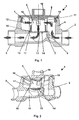
- einen perspektivischen Längsschnitt durch ein Anschlussgehäuse mit einem erfindungsgemäßen Deckel und
- Fig. 2
- einen perspektivischen Längsschnitt durch das Anschlussgehäuse mit Deckel in einer anderen Projektionsrichtung.
- Fig. 1
- a perspective longitudinal section through a connection housing with a lid according to the invention and
- Fig. 2
- a perspective longitudinal section through the connector housing with cover in another direction of projection.
In Rohrleitungssystemen für die Wasserversorgung oder den Heizkreislauf von Gebäuden ist ein Anschlussgehäuse 1 mit Leitungsabschnitten 2, 3 für die Verbindung mit den Rohrleitungen und den Flüssigkeitseintritt bzw. -austritt vorgesehen. Im Wesentlichen senkrecht zu den Leitungsabschnitten 2, 3 ist ein Gehäusestutzen 4 vorgesehen, in dem eine Gehäuseöffnung 5 zur Befestigung eines Wasser- oder Wärmezählers ausgebildet ist. Das Anschlussgehäuse 1 weist Leitflächen 6 zur Wasserführung und eine im Wesentlichen zentrale, in der Zeichnung senkrechte Austrittsöffnung 7 auf, die in den Leitungsabschnitt 3 für den Flüssigkeitsaustritt übergeht. Die Leitflächen 6 und die Austrittsöffnung 7 sind an die Erfordernisse eines in der Zeichnung nicht dargestellten Zählers angepasst und sollen eine definierte Strömungszufuhr und -abfuhr zu/von dem Zähler bewirken. Sofern der Zähler einen anderen Strömungsverlauf erfordert, kann das Anschlussgehäuse entsprechend anders ausgestaltet sein.In piping systems for the water supply or the heating circuit of buildings, a connection housing 1 is provided with
Auf dieses üblicherweise unter Putz in den Rohrleitungssystemen integrierte Anschlussgehäuse 1 wird ein erfindungsgemäßer Deckel 8 aufgesetzt, der über eine Gewinde- oder Schnappverbindung in die Gehäuseöffnung 5 eingesetzt wird. Auf der Innenseite des Deckels 8 ist ein Leitungsabschnitt 9 vorgesehen, der in seiner im Wesentlichen zylindrischen Wandung 10 radiale Eintrittsöffnungen 11, 12 für die Flüssigkeit aufweist. An dem dem Deckel 8 gegenüberliegenden Boden des Leitungsabschnittes 9 ist ein Filterelement 13 in Form eines Siebes mit einer Vielzahl von Durchtrittsöffnungen 14 vorgesehen.On this usually under plaster integrated into the piping connection housing 1, an inventive cover 8 is placed, which is inserted via a threaded or snap connection in the
Radial außen schließt sich an das Sieb 13 eine Dichtflächenabdeckung 15 an, die auf einer Dichtfläche 16 des Anschlussgehäuses 1 abgedichtet aufliegt. Das Sieb 13 ist einstückig mit dem Leitungsabschnitt 9 ausgebildet, insbesondere in die Dichtflächenabdeckung 15 eingespritzt. Zwischen dem Sieb 13 und den Eintrittsöffnungen 11, 12 ist die Wandung 10 des Leitungsabschnittes 9 als durchgehender Bund 17 ausgebildet. Der Leitungsabschnitt 9 ist über eine Schnappverbindung oder dergleichen fest mit dem Deckel 8 verbunden. Der Deckel 8 weist auf seiner Außenseite einen bspw. sechskantförmigen Vorsprung 18 für den Angriff eines Werkzeuges auf. Die Abdichtung des Deckels 8 gegenüber dem Gehäusestutzen 4 des Anschlussgehäuses 1 wird über eine Dichtung 19, bspw. einen O-Ring gewährleistet.Radially outside, the
Der erfindungsgemäße Deckel 8 mit daran angebrachtem Leitungsabschnitt 9 wird vor Inbetriebnahme der Heizungseinrichtung bzw. beim Spülen der Wasserleitung anstelle des Wärme- oder Wasserzählers in den Anschlussstutzen 1 eingesetzt. Strömt nun die Flüssigkeit durch das Anschlussgehäuse 1, so werden darin enthaltene Späne oder andere Verschmutzungen von dem Sieb 13 aufgefangen und können zusammen mit dem Deckel 8 aus dem Anschlussgehäuse 1 herausgenommen werden. Durch den umlaufenden Bund 17 wird hierbei ein Herausfallen der Schmutzteile verhindert, so dass eine sichere Entfernung der Verschmutzung gewährleistet ist. Der Deckel 8 mit dem Leitungsabschnitt 9 lässt sich anschließend problemlos ausspülen und reinigen. Aus dem Heizkreislauf bzw. der Wasserleitung sind die Verschmutzungen zuverlässig entfernt. Ein Mehraufwand für den Monteur ergibt sich nicht, da alle Arbeitsschritte im Feld die gleichen bleiben wie bei der herkömmlichen Inbetriebnahme bzw. Reinigung des Rohrleitungssystems. Dagegen entfällt die anschließende Reinigung von Perlatoren beim Durchspülen der Wasserleitungen.The cover 8 according to the invention with the
- 11
- Anschlussgehäuseconnection housing
- 22
- Leitungsabschnittline section
- 33
- Leitungsabschnittline section
- 44
- GehäusestutzenThe connection piece
- 55
- Gehäuseöffnunghousing opening
- 66
- Leitflächebaffle
- 77
- Austrittsöffnungoutlet opening
- 88th
- Deckelcover
- 99
- Leitungsabschnittline section
- 1010
- Wandungwall
- 1111
- Eintrittsöffnunginlet opening
- 1212
- Eintrittsöffnunginlet opening
- 1313
- Filterelementfilter element
- 1414
- DurchtrittsöffnungThrough opening
- 1515
- DichtflächenabdeckungSealing surface coverage
- 1616
- Dichtflächesealing surface
- 1717
- BundFederation
- 1818
- Vorsprunghead Start
- 1919
- Dichtungpoetry
Claims (6)
- Lid for a connection housing (1) of pipeline systems with line sections (2, 3) for liquid entry and liquid exit and with a housing opening (5) for mounting a flow meter, wherein the lid is meant for use instead of the flow meter, characterised by a line section (9) engaging into the housing opening (5), through which the liquid is guided, wherein a filter element (13) is arranged in the line section (9), wherein the line section (9) has at least one opening (11, 12) for liquid entry and at least one opening (14) for liquid exit.
- Lid according to Claim 1, characterised in that the line section (9) bears via a sealing surface cover (15) against a sealing surface (16) of the connection housing (1) and separates the liquid entry (2) from the liquid exit (3).
- Lid according to any one of the preceding claims, characterised in that the filter element (13) is integrally connected to the line section (9).
- Sealing element according to any one of the preceding claims, characterised in that the filter element (13) is a sieve.
- Lid according to any one of the preceding claims, characterised in that a circumferential collar (17) abuts against the filter element (13).
- Lid according to any one of the preceding claims, characterised in that the line section (9) is shaped in an essentially cylindrical manner and in that the opening (11, 12) for the flow entry is arranged in the radial direction and the opening (14) for the flow exit is arranged in the axial direction, or vice versa.
Applications Claiming Priority (4)
| Application Number | Priority Date | Filing Date | Title |
|---|---|---|---|
| DE20104768 | 2001-03-16 | ||
| DE20104768U | 2001-03-16 | ||
| DE20110697U DE20110697U1 (en) | 2001-03-16 | 2001-06-28 | Cover for connection housing of piping systems |
| DE20110697U | 2001-06-28 |
Publications (2)
| Publication Number | Publication Date |
|---|---|
| EP1241451A1 EP1241451A1 (en) | 2002-09-18 |
| EP1241451B1 true EP1241451B1 (en) | 2011-03-16 |
Family
ID=26056871
Family Applications (1)
| Application Number | Title | Priority Date | Filing Date |
|---|---|---|---|
| EP02002228A Expired - Lifetime EP1241451B1 (en) | 2001-03-16 | 2002-01-30 | Cap having a filter for collecting dirt particles for use with a water meter housing |
Country Status (5)
| Country | Link |
|---|---|
| EP (1) | EP1241451B1 (en) |
| CZ (1) | CZ2002509A3 (en) |
| HU (1) | HUP0200936A3 (en) |
| PL (1) | PL352545A1 (en) |
| SK (1) | SK1302002A3 (en) |
Families Citing this family (2)
| Publication number | Priority date | Publication date | Assignee | Title |
|---|---|---|---|---|
| DE102004055816B4 (en) * | 2004-11-18 | 2006-11-16 | Hydrometer Gmbh | fluid meter |
| EP3296704A1 (en) | 2016-09-16 | 2018-03-21 | Energoflow AG | Flowmeter |
Citations (3)
| Publication number | Priority date | Publication date | Assignee | Title |
|---|---|---|---|---|
| GB2286975A (en) * | 1994-03-03 | 1995-09-06 | Evans Gerald J | In-line meter assembly |
| EP0713078A1 (en) * | 1994-11-15 | 1996-05-22 | E. Wehrle GmbH | Measuring insert for flow rate sensors |
| EP1111350A1 (en) * | 1999-12-13 | 2001-06-27 | SPANNER-POLLUX GmbH | Water meter |
Family Cites Families (2)
| Publication number | Priority date | Publication date | Assignee | Title |
|---|---|---|---|---|
| FR2541131A1 (en) * | 1983-02-21 | 1984-08-24 | Morgan Howard Jun | Filter with a removable filter basket |
| DE29902509U1 (en) * | 1999-02-12 | 1999-06-02 | Techem AG & Co., 60528 Frankfurt | Arrangement for securing a measuring capsule of a water meter and sealing ring therefor |
-
2002
- 2002-01-25 SK SK130-2002A patent/SK1302002A3/en unknown
- 2002-01-30 EP EP02002228A patent/EP1241451B1/en not_active Expired - Lifetime
- 2002-02-11 CZ CZ2002509A patent/CZ2002509A3/en unknown
- 2002-02-28 PL PL02352545A patent/PL352545A1/en not_active IP Right Cessation
- 2002-03-12 HU HU0200936A patent/HUP0200936A3/en unknown
Patent Citations (3)
| Publication number | Priority date | Publication date | Assignee | Title |
|---|---|---|---|---|
| GB2286975A (en) * | 1994-03-03 | 1995-09-06 | Evans Gerald J | In-line meter assembly |
| EP0713078A1 (en) * | 1994-11-15 | 1996-05-22 | E. Wehrle GmbH | Measuring insert for flow rate sensors |
| EP1111350A1 (en) * | 1999-12-13 | 2001-06-27 | SPANNER-POLLUX GmbH | Water meter |
Also Published As
| Publication number | Publication date |
|---|---|
| HU0200936D0 (en) | 2002-05-29 |
| HUP0200936A3 (en) | 2003-02-28 |
| PL352545A1 (en) | 2002-09-23 |
| SK1302002A3 (en) | 2002-10-08 |
| EP1241451A1 (en) | 2002-09-18 |
| CZ2002509A3 (en) | 2002-11-13 |
| HUP0200936A2 (en) | 2002-09-28 |
Similar Documents
| Publication | Publication Date | Title |
|---|---|---|
| EP0593490B1 (en) | Check valve | |
| DE29909100U1 (en) | Pipe arrangement with filter | |
| DE3502969A1 (en) | METHOD AND DEVICE FOR CLEANING A PIPELINE | |
| EP2998449A1 (en) | Bathroom drain fitting | |
| EP0261326B1 (en) | Corner valve for building water mains | |
| EP3208391B1 (en) | Safety device | |
| EP1241451B1 (en) | Cap having a filter for collecting dirt particles for use with a water meter housing | |
| EP0513705A1 (en) | Heat exchanger for waste water piping | |
| EP3173538B1 (en) | Connection device | |
| DE20110697U1 (en) | Cover for connection housing of piping systems | |
| EP3575661B1 (en) | Rinsing and sampling device for a domestic water connection | |
| EP0984106B1 (en) | Transparent filter for water conduits of sanitary installations | |
| EP2801672B1 (en) | System separator | |
| EP2484839B1 (en) | Drinking and domestic water system and method for installing same | |
| DE4444940A1 (en) | Connecting pipes | |
| DE102020113929A1 (en) | Pipe section of a measuring tube in a process plant for hygiene applications and arrangement in such a process plant | |
| DE10228535B4 (en) | Arrangement for the storage of a filter insert for a heating system | |
| DE202018102599U1 (en) | safety valve | |
| EP3683367B1 (en) | Washbasin installation assembly and method of assembling a washbasin installation assembly | |
| EP3543391A1 (en) | Device for securing the drinking water for a washing machine and washing machine | |
| WO2004022202A1 (en) | Liquid filter, particularly for transmission oil in motor vehicles | |
| DE19545446C2 (en) | Both ends with a shut-off device provided with a shut-off bypass line leading around the line section | |
| DE69514700T2 (en) | Safety device for installation between a line of a drinking water supply network and a supply line of a consumer device, such as a boiler | |
| DE19701846C2 (en) | Safety device for an unpressurized mixer and its use for protecting an unpressurized boiler | |
| DE20014321U1 (en) | Device for distributing liquids, especially water, in drinking and industrial water systems or the like. |
Legal Events
| Date | Code | Title | Description |
|---|---|---|---|
| PUAI | Public reference made under article 153(3) epc to a published international application that has entered the european phase |
Free format text: ORIGINAL CODE: 0009012 |
|
| AK | Designated contracting states |
Kind code of ref document: A1 Designated state(s): AT BE CH CY DE DK ES FI FR GB GR IE IT LI LU MC NL PT SE TR |
|
| AX | Request for extension of the european patent |
Free format text: AL;LT;LV;MK;RO;SI |
|
| 17P | Request for examination filed |
Effective date: 20020829 |
|
| AKX | Designation fees paid |
Designated state(s): AT CH DE FR LI |
|
| RAP1 | Party data changed (applicant data changed or rights of an application transferred) |
Owner name: TECHEM ENERGY SERVICES GMBH |
|
| 17Q | First examination report despatched |
Effective date: 20070521 |
|
| RTI1 | Title (correction) |
Free format text: COVER FOR A WATER FLOW METER HOUSING COMPRISING A FILTER FOR COLLECTING DIRT PARTICLES |
|
| GRAP | Despatch of communication of intention to grant a patent |
Free format text: ORIGINAL CODE: EPIDOSNIGR1 |
|
| RTI1 | Title (correction) |
Free format text: CAP HAVING A FILTER FOR COLLECTING DIRT PARTICLES FOR USE WITH A WATER METER HOUSING |
|
| GRAS | Grant fee paid |
Free format text: ORIGINAL CODE: EPIDOSNIGR3 |
|
| GRAA | (expected) grant |
Free format text: ORIGINAL CODE: 0009210 |
|
| AK | Designated contracting states |
Kind code of ref document: B1 Designated state(s): AT CH DE FR LI |
|
| REG | Reference to a national code |
Ref country code: CH Ref legal event code: EP |
|
| REF | Corresponds to: |
Ref document number: 50214953 Country of ref document: DE Date of ref document: 20110428 Kind code of ref document: P |
|
| REG | Reference to a national code |
Ref country code: DE Ref legal event code: R096 Ref document number: 50214953 Country of ref document: DE Effective date: 20110428 |
|
| REG | Reference to a national code |
Ref country code: CH Ref legal event code: NV Representative=s name: BOHEST AG |
|
| PLBE | No opposition filed within time limit |
Free format text: ORIGINAL CODE: 0009261 |
|
| STAA | Information on the status of an ep patent application or granted ep patent |
Free format text: STATUS: NO OPPOSITION FILED WITHIN TIME LIMIT |
|
| 26N | No opposition filed |
Effective date: 20111219 |
|
| REG | Reference to a national code |
Ref country code: DE Ref legal event code: R097 Ref document number: 50214953 Country of ref document: DE Effective date: 20111219 |
|
| REG | Reference to a national code |
Ref country code: CH Ref legal event code: PCAR Free format text: NEW ADDRESS: HOLBEINSTRASSE 36-38, 4051 BASEL (CH) |
|
| REG | Reference to a national code |
Ref country code: FR Ref legal event code: PLFP Year of fee payment: 15 |
|
| REG | Reference to a national code |
Ref country code: FR Ref legal event code: PLFP Year of fee payment: 16 |
|
| REG | Reference to a national code |
Ref country code: FR Ref legal event code: PLFP Year of fee payment: 17 |
|
| PGFP | Annual fee paid to national office [announced via postgrant information from national office to epo] |
Ref country code: DE Payment date: 20180209 Year of fee payment: 17 Ref country code: CH Payment date: 20180125 Year of fee payment: 17 |
|
| PGFP | Annual fee paid to national office [announced via postgrant information from national office to epo] |
Ref country code: FR Payment date: 20180124 Year of fee payment: 17 Ref country code: AT Payment date: 20180122 Year of fee payment: 17 |
|
| REG | Reference to a national code |
Ref country code: DE Ref legal event code: R119 Ref document number: 50214953 Country of ref document: DE |
|
| REG | Reference to a national code |
Ref country code: CH Ref legal event code: PL |
|
| REG | Reference to a national code |
Ref country code: AT Ref legal event code: MM01 Ref document number: 502281 Country of ref document: AT Kind code of ref document: T Effective date: 20190130 |
|
| PG25 | Lapsed in a contracting state [announced via postgrant information from national office to epo] |
Ref country code: FR Free format text: LAPSE BECAUSE OF NON-PAYMENT OF DUE FEES Effective date: 20190131 Ref country code: DE Free format text: LAPSE BECAUSE OF NON-PAYMENT OF DUE FEES Effective date: 20190801 |
|
| PG25 | Lapsed in a contracting state [announced via postgrant information from national office to epo] |
Ref country code: AT Free format text: LAPSE BECAUSE OF NON-PAYMENT OF DUE FEES Effective date: 20190130 Ref country code: CH Free format text: LAPSE BECAUSE OF NON-PAYMENT OF DUE FEES Effective date: 20190131 Ref country code: LI Free format text: LAPSE BECAUSE OF NON-PAYMENT OF DUE FEES Effective date: 20190131 |