EP1241439A2 - Verfahren und Vorrichtung zum Vermessen von Profilrohren - Google Patents
Verfahren und Vorrichtung zum Vermessen von Profilrohren Download PDFInfo
- Publication number
- EP1241439A2 EP1241439A2 EP02090051A EP02090051A EP1241439A2 EP 1241439 A2 EP1241439 A2 EP 1241439A2 EP 02090051 A EP02090051 A EP 02090051A EP 02090051 A EP02090051 A EP 02090051A EP 1241439 A2 EP1241439 A2 EP 1241439A2
- Authority
- EP
- European Patent Office
- Prior art keywords
- laser
- measurement
- laser sensor
- computer
- profile
- Prior art date
- Legal status (The legal status is an assumption and is not a legal conclusion. Google has not performed a legal analysis and makes no representation as to the accuracy of the status listed.)
- Withdrawn
Links
- 238000000034 method Methods 0.000 title claims abstract description 22
- 238000005259 measurement Methods 0.000 claims abstract description 40
- 238000001028 reflection method Methods 0.000 claims abstract description 4
- 238000004513 sizing Methods 0.000 claims description 10
- 238000003466 welding Methods 0.000 claims description 8
- 238000012937 correction Methods 0.000 claims description 2
- 230000002441 reversible effect Effects 0.000 claims description 2
- 238000004519 manufacturing process Methods 0.000 abstract description 9
- 238000005286 illumination Methods 0.000 description 2
- 239000000523 sample Substances 0.000 description 2
- 235000013405 beer Nutrition 0.000 description 1
- 239000007795 chemical reaction product Substances 0.000 description 1
- 238000001514 detection method Methods 0.000 description 1
- 238000011156 evaluation Methods 0.000 description 1
- 230000002349 favourable effect Effects 0.000 description 1
- 238000003754 machining Methods 0.000 description 1
- 239000000047 product Substances 0.000 description 1
- 238000005096 rolling process Methods 0.000 description 1
- 238000012800 visualization Methods 0.000 description 1
Images

Classifications
-
- G—PHYSICS
- G01—MEASURING; TESTING
- G01B—MEASURING LENGTH, THICKNESS OR SIMILAR LINEAR DIMENSIONS; MEASURING ANGLES; MEASURING AREAS; MEASURING IRREGULARITIES OF SURFACES OR CONTOURS
- G01B11/00—Measuring arrangements characterised by the use of optical techniques
- G01B11/24—Measuring arrangements characterised by the use of optical techniques for measuring contours or curvatures
-
- G—PHYSICS
- G01—MEASURING; TESTING
- G01B—MEASURING LENGTH, THICKNESS OR SIMILAR LINEAR DIMENSIONS; MEASURING ANGLES; MEASURING AREAS; MEASURING IRREGULARITIES OF SURFACES OR CONTOURS
- G01B11/00—Measuring arrangements characterised by the use of optical techniques
- G01B11/24—Measuring arrangements characterised by the use of optical techniques for measuring contours or curvatures
- G01B11/245—Measuring arrangements characterised by the use of optical techniques for measuring contours or curvatures using a plurality of fixed, simultaneously operating transducers
Definitions
- the invention relates to a method and a device for contactless Determining and measuring the surface contour of measurement objects, in particular Profile tubes in which with at least one scanning in a scanning plane Laser measurement system scanned the surface of the respective measurement object and for everyone detected point on the surface of the measuring object, its position in space determined is, the respective measurement object and the Laser measurement system can be moved linearly and rotationally relative to each other
- a method and a device for determining the surface contours of measurement objects of any shape is known from DE 197 41 730 A1. With that one The proposed solution can, for example, record body measurements become. But also individual body parts, e.g. Hands can be with the system recognize, movements in the room are detectable. Finally, too Objects such as beer crates, objects such as tunnels or other interiors with the known system are measured or recorded, the used Laser measuring systems Relative movements between the measuring system and the respective Evaluate the measurement object.
- the known system is diverse for the acquisition and measurement of various Objects can be used.
- the system is not easy to use, because there are special Requirements placed on the measuring method and the corresponding device. It It has been shown that the exact measurement of the profile contour of a continuous manufactured pipe is indispensable because during the manufacturing process caused external influences, the dimensional accuracy of the profile tube often Fluctuations. Dimensional inaccuracies are currently recorded by Touch measurement on the profile tube when the system is shut down or offline on finished pipe. To measure round tubes are also already stationary or rotating measuring heads are used, which use the illumination method via a or several axes determine the diameter and ovality of the pipe.
- the present invention is based on the problems described, the The task is to further develop the method of the type described at the beginning and to create a device with which the surface contour measurements Profile pipes on the running strand, i.e. are feasible during production with the goal of recognizing dimensional deviations at an early stage and if necessary ligament.
- a method is proposed which is characterized in that for determining and measuring the surface contour of Profile tubes on the running pipe string at least one laser sensor of the Laser measurement system in a plane running transverse to the longitudinal axis of the profile tube is rotated around the profile tube and the reflection process Distances from the laser sensor to the surface of the profile tube measures that the received Measured values together with the information collected simultaneously about the position of the laser sensor assigned to each measuring point on a computer can be supplied in which, with the help of evaluation software, a geometric surface contour is calculated using a stored in the computer Setpoint surface contour is compared, deviations from the setpoint are displayed.
- the proposed method can advantageously be done online while it is running Execute machining and or manufacturing process so that the plant comes to a standstill with the resulting inevitable amount of scrap.
- Displaying setpoint deviations can quickly identify errors and theirs The cause can be counteracted.
- the method according to the invention can be particularly advantageously carried out in Use longitudinal seam tube welding system to manufacture profile tubes if after another feature of the invention at the outlet of the Longitudinal seam tube welding system recorded behind the sizing mill and in the computer processed measured values in the event of deviations from the specified target value Output limit signals and generate manipulated variables that can be controlled online the setpoint deviations the control loop of the employment of the sizing mill be fed.
- the dimensional accuracy can be achieved without the plant being down measure and detect irregularities on out of tolerance profile tubes can be corrected immediately during the manufacturing process by the sizing mill is adjusted accordingly.
- the measured values and in particular the deviations from the specified ones Setpoints can be visualized according to another feature of the invention, i.e. are preferably displayed on the computer screen.
- a device for contactless determination and measurement is the surface contour of measurement objects, in particular profile tubes characterized by a at the outlet of a longitudinal seam tube welding system behind the Sizing mill provided measuring arrangement, with one that is longitudinally welded Profile tube in a transverse plane encompassing orbit for at least one in Reflection method measuring laser sensor, with a position sensor for detection the respective position of the laser sensor in relation to the profile tube and with a Computer for evaluating the from the laser sensor and the position transmitter determined measured values.
- the longitudinally welded profile tube runs through the center Measuring arrangement, while at the same time the laser sensor or sensors the profile tube Drive around at least in sections.
- the computer is provided a screen for visualization of the measured values and for forwarding Correction signals with the adjustment control system of the sizing mill To connect longitudinal seam pipe welding system. That way you can Production process errors made visible on the one hand and on the other hand can be controlled online without the need for measuring scrap or setting scrap.
- the laser probe or the laser probes are on one in the Measuring arrangement attached to the longitudinal axis of the profile tube rotatably mounted ring, which can be driven on its circumference by a reversible rotary drive is.
- the laser sensors can thus be relatively easily in any angular amount can be swiveled around the profile tube on a precisely defined path, the respective position of the laser sensor simply via the swivel position of the ring from the position sensor is detectable.
- the angle of rotation of the rotary bearing Ring at least 360 ° divided by the number of evenly on the circumference distributed laser sensors. That means, for example, with two Laser sensors have a rotation angle of 180 ° for each laser sensor.
- the laser sensor or the laser sensors can have a two- or three-axis control, specifically for a horizontal, vertical and, if necessary, swiveling movement, which in combination lead to an orbit encompassing the transverse plane.
- the advantage of using a two- or three-axis control system can also be seen in the fact that not only can a circular orbit be generated with an electronic control of this type, but also other, non-circular orbits can be programmed.
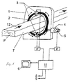
- the frame-like frame is designated, in which a ring 2 around its Central axis is rotatably mounted.
- the ring 2 is a rotary drive 4 in the one or the other direction of rotation.
- a position sensor 5 with which the respective rotational position of the ring 2 is detectable.
- On the ring 2 are even on its circumference distributed two laser sensors 3 attached, the distance of the reflection process respective laser sensor 3 from the surface 7 of the ring 2 in Detect the direction of movement 12 of the profile tube P that is passed.
- Both the Measurement value of the laser sensor 3 as well as that of the position sensor 5 are the Computer 11 supplied, where the values to a geometric surface contour will be charged.
- the evaluation is stored in a computer 11 Software compared. The result is visualized on monitor 6.
- Limits 8 are output and as control value 9 for the control loop of the employment of (not shown) sizing mill returned.
- annular plane of rotation for the Laser system is used, it is also within the scope of the invention a defined to use another form of rotation.
- the schematic representation in FIG. 2 indicates that the Laser sensors have a horizontal movement x, a vertical movement y and one Carry out swiveling movement z.
Landscapes
- Physics & Mathematics (AREA)
- General Physics & Mathematics (AREA)
- Length Measuring Devices By Optical Means (AREA)
Abstract
Description
Auch hierbei kann man dann mit zwei Lasersensoren auskommen, die jeweils einen Umlaufwinkel von 180° bestreichen.
Der Vorteil, der Anwendung einer Zwei - oder Dreiachsen-Steuerung ist weiterhin darin zu sehen, dass mit einer elektronischen Steuerung dieser Art nicht nur eine kreisförmige Umlaufbahn erzeugt werden kann, sondern auch andere, nichtkreisförmige Umlaufbahnen programmierbar sind.
Claims (8)
- Verfahren zum berührungslosen Ermitteln und Vermessen der Oberflächenkontur von Messobjekten, insbesondere Profilrohren, bei dem mit wenigstens einem in einer Abtastebene abtastenden Lasermeßsystem die Oberfläche des jeweiligen Messobjektes abgetastet und für jeden ertasteten Punkt auf der Messobjektoberfläche dessen Position im Raum ermittelt wird, wobei während der Abtastung das jeweilige Messobjekt und das Lasermeßsystem relativ zueinander linear und rotatorisch bewegt werden,
dadurch gekennzeichnet, dass zum Ermitteln und Vermessen der Oberflächenkontur von Profilrohren am laufenden Rohrstrang mindestens ein Lasersensor des Lasermeßsystems in einer quer zur Längsachse der Profilrohres verlaufenden Ebene rotierend um das Profilrohr geführt wird und dabei im Reflektionsverfahren die Abstände vom Lasersensor zur Oberfläche des Profilrohres misst, dass die erhaltenen Messwerte zusammen mit den gleichzeitig erfassten Informationen über die dem jeweiligen Messpunkt zugeordnete Position des Lasersensors einem Rechner zugeführt werden, in dem mit Hilfe einer Auswertesoftware aus den Messwerten eine geometrische Oberflächenkontur errechnet wird, die mit einer im Rechner hinterlegten Sollwert-Oberflächenkontur verglichen wird, wobei Abweichungen vom Sollwert angezeigt werden. - Verfahren nach Anspruch 1,
dadurch gekennzeichnet, dass die am Auslauf einer Längsnahtrohrschweißanlage hinter dem Maßwalzwerk erfassten und im Rechner verarbeiteten Messwerte bei Abweichungen vom vorgegebene Sollwert Grenzwertsignale ausgeben und Stellgrößen generieren, die Online zum Aussteuern der Sollwertabweichungen dem Regelkreis der Anstellung des Maßwalzwerkes zugeführt werden. - Verfahren nach Anspruch 1 und 2,
dadurch gekennzeichnet, dass die im Rechner ermittelten Abweichungen vom Sollwert visualisiert werden. - Vorrichtung zum berührungslosen Ermitteln und Vermessen der Oberflächenkontur von Messobjekten, insbesondere Profilrohren, bei dem mit wenigstens einem in einer Abtastebene abtastenden Lasermeßsystem die Oberfläche des jeweiligen Messobjektes abgetastet und für jeden ertasteten Punkt auf der Messobjektoberfläche dessen Position im Raum ermittelt wird, wobei während der Abtastung das jeweilige Messobjekt und das Lasermeßsystem relativ zueinander linear und rotatorisch bewegt werden, gekennzeichnet durch,
eine am Auslauf einer Längsnahtrohrschweißanlage hinter dem Maßwalzwerk vorgesehene Messanordnung (1), mit einer das längsnahtgeschweißte Profilrohr (P) in einer Querebene umgreifenden Umlaufbahn für mindestens einen im Relexionsverfahren messenden Lasersensor (3), mit einem Positionsgeber (5) zur Erfassung der jeweiligen Position des Lasersensors (3) in Bezug auf das Profilrohr (P) und mit einem Rechner (11) zur Auswertung der von dem Lasersensor (3) und dem Positionsgeber (5) ermittelten Messwerte. - Vorrichtung nach Anspruch 4,
dadurch gekennzeichnet, dass der Rechner (11) mit einem Bildschirm (6) zur Visualisierung der Messwerte sowie zur Ausgabe von Korrektursignalen mit dem Anstellungssteuerungssystem des Maßwalzwerkes der Längsnahtrohrschweißanlage verbunden ist. - Vorrichtung nach Anspruch 4 oder 5,
dadurch gekennzeichnet, dass der Lasersensor oder die Lasersensoren (3) auf einem in der Messanordnung (1) um die Längsachse des Profilrohres (P) drehgelagerten Ring (2) befestigt sind, der an seinem Umfang von einen richtungsumsteuerbaren Rotationsantrieb (4) antreibbar ist. - Vorrichtung nach einem der Ansprüche 4 bis 6,
dadurch gekennzeichnet, dass der Drehwinkel des drehgelagerten Ringes (2) mindestens 360° geteilt durch die Anzahl der gleichmäßig auf dem Umfang verteilt angeordneten Lasersensoren (3) beträgt - Vorrichtung nach Anspruch 4,
dadurch gekennzeichnet, dass der Lasersensor oder die Lasersensoren über eine Zwei - oder Dreiachsen-Steuerung verfügen, und zwar für eine horizontale, vertikale und - falls erforderlich - Schwenk-Bewegung, die in der Kombination zu einer die Querebene umgreifenden Umlaufbahn führen.
Applications Claiming Priority (2)
| Application Number | Priority Date | Filing Date | Title |
|---|---|---|---|
| DE10108812 | 2001-02-16 | ||
| DE2001108812 DE10108812A1 (de) | 2001-02-16 | 2001-02-16 | Verfahren und Vorrichtung zum Vermessen von Profilrohren |
Publications (2)
| Publication Number | Publication Date |
|---|---|
| EP1241439A2 true EP1241439A2 (de) | 2002-09-18 |
| EP1241439A3 EP1241439A3 (de) | 2003-11-05 |
Family
ID=7675281
Family Applications (1)
| Application Number | Title | Priority Date | Filing Date |
|---|---|---|---|
| EP02090051A Withdrawn EP1241439A3 (de) | 2001-02-16 | 2002-02-08 | Verfahren und Vorrichtung zum Vermessen von Profilrohren |
Country Status (2)
| Country | Link |
|---|---|
| EP (1) | EP1241439A3 (de) |
| DE (1) | DE10108812A1 (de) |
Cited By (3)
| Publication number | Priority date | Publication date | Assignee | Title |
|---|---|---|---|---|
| CN117086118A (zh) * | 2023-08-11 | 2023-11-21 | 索罗曼(广州)新材料有限公司 | 一种用于钛扁条热轧工艺的自动检测装置及方法 |
| DE102022207070A1 (de) | 2022-07-11 | 2024-01-11 | Robert Bosch Gesellschaft mit beschränkter Haftung | Verfahren zur Erkennung von Anomalien auf einer Oberfläche eines Objektes |
| DE102023201749A1 (de) | 2023-02-27 | 2024-08-29 | Robert Bosch Gesellschaft mit beschränkter Haftung | Verfahren zum Trainieren eines Ensemble Algorithmus des maschinellen Lernens zum Klassifizieren von Bilddaten |
Families Citing this family (5)
| Publication number | Priority date | Publication date | Assignee | Title |
|---|---|---|---|---|
| DE102016205469A1 (de) * | 2016-04-01 | 2017-10-05 | Wobben Properties Gmbh | Messsystem zur Vermessung einer Oberfläche |
| CN106017392B (zh) * | 2016-07-21 | 2018-09-11 | 浙江海澄德畅机械有限公司 | 多点同时检测电力铁塔钢管圆截面轮廓及同轴度的方法 |
| CN106197316B (zh) * | 2016-07-21 | 2018-10-26 | 谢灵卫 | 利用求平均值法进行电力铁塔钢管圆截面轮廓检测的方法 |
| CN113203362B (zh) * | 2021-04-01 | 2025-03-04 | 新兴河北工程技术有限公司 | 一种适用于铸管生产线的直径检测方法及装置 |
| CN118031847B (zh) * | 2024-04-10 | 2024-06-04 | 甘肃祁连山国家级自然保护区管护中心大河口自然保护站(大熊猫祁连山国家公园甘肃省管理局张掖分局大河口保护站) | 一种周期式树木生长直径监测方法和系统 |
Family Cites Families (6)
| Publication number | Priority date | Publication date | Assignee | Title |
|---|---|---|---|---|
| CH379779A (de) * | 1960-10-22 | 1964-07-15 | Fischer & Co E | Verfahren zur Ermittlung des Aufbaus eines aus Mantel und Kern bestehenden Körpers |
| US4264208A (en) * | 1978-10-25 | 1981-04-28 | Semperit Aktiengesellschaft | Method and apparatus for measuring the surface of an object |
| DD224658B5 (de) * | 1984-05-21 | 1994-05-26 | Sket Schwermaschbau Gmbh | Verfahren zur Verwertung der Messwerte doppelt symmetrischer Walzgutquerschnitte |
| DE3934236A1 (de) * | 1988-10-18 | 1990-04-19 | Hasenclever Maschf Sms | Verfahren und vorrichtung zum bestimmen der geometrie eines koerpers |
| JPH09243333A (ja) * | 1996-03-06 | 1997-09-19 | Kinugawa Rubber Ind Co Ltd | 押出成形品の検査装置 |
| GB9805445D0 (en) * | 1998-03-16 | 1998-05-13 | Whitehouse John A | Product scanner |
-
2001
- 2001-02-16 DE DE2001108812 patent/DE10108812A1/de not_active Withdrawn
-
2002
- 2002-02-08 EP EP02090051A patent/EP1241439A3/de not_active Withdrawn
Cited By (3)
| Publication number | Priority date | Publication date | Assignee | Title |
|---|---|---|---|---|
| DE102022207070A1 (de) | 2022-07-11 | 2024-01-11 | Robert Bosch Gesellschaft mit beschränkter Haftung | Verfahren zur Erkennung von Anomalien auf einer Oberfläche eines Objektes |
| DE102023201749A1 (de) | 2023-02-27 | 2024-08-29 | Robert Bosch Gesellschaft mit beschränkter Haftung | Verfahren zum Trainieren eines Ensemble Algorithmus des maschinellen Lernens zum Klassifizieren von Bilddaten |
| CN117086118A (zh) * | 2023-08-11 | 2023-11-21 | 索罗曼(广州)新材料有限公司 | 一种用于钛扁条热轧工艺的自动检测装置及方法 |
Also Published As
| Publication number | Publication date |
|---|---|
| EP1241439A3 (de) | 2003-11-05 |
| DE10108812A1 (de) | 2002-09-05 |
Similar Documents
| Publication | Publication Date | Title |
|---|---|---|
| DE102011119658B4 (de) | Verfahren und Vorrichtung zum Prüfen von Rohren | |
| EP1137515B9 (de) | Verfahren und schleifmaschine zur prozessführung beim schälschleifen eines werkstückes | |
| DE60021837T2 (de) | KMM V-Spiralnuten Formmessung ( Gewinde, Innengewinde, Schneckenrad ) mit Drehtisch und Zweiflankenkontakt | |
| DE102008061444B4 (de) | Drehmaschine mit einer Messvorrichtung und Verfahren zum Vermessen eines Werkstückes auf solch einer Drehmaschine | |
| DE102008057309B3 (de) | Verfahren und Laserbearbeitungsmaschine zum Ermitteln einer Dejustage einer Pulverzufuhrdüse der Laserbearbeitungsmaschine | |
| EP2190626B1 (de) | Verfahren und einrichtung zur bearbeitung von werkstücken | |
| DE69506779T2 (de) | System zur automatischen Kontrolle der Schweissfugenform im Orbitalschweissverfahren für Rohre mit mittleren bis grossen Abmessungen | |
| WO2007121953A1 (de) | Vorrichtung zum automatischen aufbringen oder erzeugen und überwachen einer auf einem substrat aufgebrachten struktur mit ermittlung von geometrischen abmessungen sowie ein entsprechendes verfahren hierfür | |
| DE19928500A1 (de) | Verfahren und Vorrichtung zur automatischen Messung von Prozess- und Werkstückkennwerten beim Schleifen von Zahnrädern | |
| EP1696289A1 (de) | Verfahren zum Vermessen einer programmgesteuerten Werkzeugmaschine | |
| EP1102033A2 (de) | Verfahren und Vorrichtung zur berührungslosen online Heisswanddickenmessung an Rohren | |
| DE10012647A1 (de) | Einrichtverfahren für ein Bearbeitungswerkzeug bzw. Werkstück auf einer Verzahnungsmaschine | |
| DE102018124208B4 (de) | Verfahren und Vorrichtung zur Überwachung eines Laserbearbeitungsprozesses an einem Werkstück sowie dazugehöriges Laserbearbeitungssystem | |
| DE102006013584A1 (de) | Vorrichtung und Verfahren zum Vermessen von Bauteilen | |
| EP1493527A1 (de) | Verfahren und Einrichtung zur Herstellung geschweisster Schraubennahtrohre aus Warmbandstahl | |
| DE102007050482B4 (de) | Verfahren und Vorrichtung zur Finishbearbeitung | |
| DE10108812A1 (de) | Verfahren und Vorrichtung zum Vermessen von Profilrohren | |
| DE102008029063B4 (de) | Verfahren und Vorrichtung zum Aufbringen einer Applikationsstruktur auf ein Werkstück sowie zum Überwachen der Applikationsstruktur | |
| DE10349948B3 (de) | Verfahren und Vorrichtung zur Prüfung eines eine komplexe Oberflächenkontur aufweisenden Bauteils mittels Ultraschall | |
| DE102011056819A1 (de) | Verfahren zur Bestimmung der Hüllkontur eines Werkstücks | |
| EP2604352A1 (de) | Verfahren zur Überwachung des Fertigungsprozesses von warmgefertigten Rohren aus Stahl | |
| DE4403951C2 (de) | Meßverfahren und Meßeinrichtung für Radsätze von Schienenfahrzeugen | |
| EP2616763A2 (de) | Verfahren zur messung der profilgeometrie von gekrümmten, insbesondere zylindrischen körpern | |
| DE10130937C1 (de) | Verfahren und Vorrichtung zur Ermittlung der Raumgeometrie eines gebogenen Strangprofils | |
| DE602004000096T2 (de) | Vorrichtung zum Kontrollieren der Position einer Spindel in einer Werkzeugmaschine |
Legal Events
| Date | Code | Title | Description |
|---|---|---|---|
| PUAI | Public reference made under article 153(3) epc to a published international application that has entered the european phase |
Free format text: ORIGINAL CODE: 0009012 |
|
| AK | Designated contracting states |
Kind code of ref document: A2 Designated state(s): AT BE CH CY DE DK ES FI FR GB GR IE IT LI LU MC NL PT SE TR |
|
| AX | Request for extension of the european patent |
Free format text: AL;LT;LV;MK;RO;SI |
|
| PUAL | Search report despatched |
Free format text: ORIGINAL CODE: 0009013 |
|
| AK | Designated contracting states |
Kind code of ref document: A3 Designated state(s): AT BE CH CY DE DK ES FI FR GB GR IE IT LI LU MC NL PT SE TR |
|
| AX | Request for extension of the european patent |
Extension state: AL LT LV MK RO SI |
|
| RIC1 | Information provided on ipc code assigned before grant |
Ipc: 7G 01B 11/24 B Ipc: 7G 01B 11/00 A |
|
| STAA | Information on the status of an ep patent application or granted ep patent |
Free format text: STATUS: THE APPLICATION HAS BEEN WITHDRAWN |
|
| 18W | Application withdrawn |
Effective date: 20040129 |