EP1241081A2 - Rear body structure for vehicle - Google Patents
Rear body structure for vehicle Download PDFInfo
- Publication number
- EP1241081A2 EP1241081A2 EP02251871A EP02251871A EP1241081A2 EP 1241081 A2 EP1241081 A2 EP 1241081A2 EP 02251871 A EP02251871 A EP 02251871A EP 02251871 A EP02251871 A EP 02251871A EP 1241081 A2 EP1241081 A2 EP 1241081A2
- Authority
- EP
- European Patent Office
- Prior art keywords
- reinforcement member
- seat
- floor panel
- vehicle
- Prior art date
- Legal status (The legal status is an assumption and is not a legal conclusion. Google has not performed a legal analysis and makes no representation as to the accuracy of the status listed.)
- Granted
Links
Images


Classifications
-
- B—PERFORMING OPERATIONS; TRANSPORTING
- B62—LAND VEHICLES FOR TRAVELLING OTHERWISE THAN ON RAILS
- B62D—MOTOR VEHICLES; TRAILERS
- B62D21/00—Understructures, i.e. chassis frame on which a vehicle body may be mounted
- B62D21/15—Understructures, i.e. chassis frame on which a vehicle body may be mounted having impact absorbing means, e.g. a frame designed to permanently or temporarily change shape or dimension upon impact with another body
- B62D21/152—Front or rear frames
-
- B—PERFORMING OPERATIONS; TRANSPORTING
- B62—LAND VEHICLES FOR TRAVELLING OTHERWISE THAN ON RAILS
- B62D—MOTOR VEHICLES; TRAILERS
- B62D43/00—Spare wheel stowing, holding, or mounting arrangements
- B62D43/06—Spare wheel stowing, holding, or mounting arrangements within the vehicle body
- B62D43/10—Spare wheel stowing, holding, or mounting arrangements within the vehicle body and arranged substantially horizontally
Definitions
- the present invention relates to a structure of a rear part of a vehicle body and more particularly to a structure including a pocket provided on a floor panel for accommodating a vehicle spare tire assembly therein and a reinforcement member covering an opening of the pocket.
- a vehicle spare tire assembly (hereinafter, referred to as just "spare tire”) is accommodated in a pocket having a predetermined depth and formed in a rear part of a floor panel of a vehicle.
- Some station wagon types or one box type vehicles have a plurality of seat rows arranged in a longitudinal direction of a passenger compartment thereof. Accordingly, sometimes the pocket comes under rearmost seat rows.
- the rearmost seats in general, are detachable from a vehicle body for the purpose of bringing the spare tire out or for changing layouts of the passenger compartment. Further, the rearmost seats are secured to a reinforcement member extending in the widthwise direction of the vehicle and the reinforcement member is rigidly connected to the vehicle body.
- the rearmost seat integrally includes the reinforcement member extending in the widthwise direction of the vehicle, it is difficult to divide the rearmost seat into left and right sections and therefore the seat has a large volume and a large weight, leading to a difficulty in installing or displacing the seat and providing restrictions in designing the seat.
- a rear body structure comprises a reinforcement member hingedly connected with a floor panel and covering at least a part of an opening of a pocket for accommodating a spare tire to prevent the spare tire from moving, a seat fixing section provided on the reinforcement member for detachably fixing the seat and a seat belt anchoring section provided on the reinforcement member for anchoring an end portion of a seat belt.
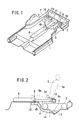
- a floor panel 1 has a pocket 2 at the rear end portion thereof and a spare tire 3 is housed in the pocket 2. Further, a reinforcement member 4 is provided so as to partially cover an opening of the pocket 2. A seat 5 disposed above the pocket 2 is detachably connected with the reinforcement member 4.
- the floor panel 1 constitutes a substantially flat floor of a vehicle body. Further, a center member 6 longitudinally and rearwardly extends along a lateral center of the floor panel at the front of the pocket. Further, a pair of side members 7, 7 extending in a longitudinal direction of the vehicle are disposed at both widthwise ends of the floor panel 1. The center member 6 and side members 7 are secured to the floor panel 1 by welding, respectively.
- the center member 6 has an inverse U-shaped cross section when viewed longitudinally and is connected at the rear end thereof with the reinforcement member 4.
- the reinforcement member 4 is interlocked with respective side members 7, 7 by a lock-up mechanism which will be described hereinafter.
- the pocket 2 extends longitudinally from the rear end of the floor panel 1 and is shaped in a semi-circle at the front half thereof.
- the spare tire 3 is accommodated in the pocket 2 and is secured to the pocket 2 by a clamp (not shown) and the like.
- the reinforcement member 4 has a T-shaped configuration and is constituted by two elongated tubular beams having a rectangular cross section. That is, the reinforcement member 4 has a transverse section 4a extending in a lateral direction and a connecting section 4b forwardly extending from the mid-portion of the transverse section 4a . As shown in Fig. 4, the transverse section 4a can be locked up at both ends thereof with respective side members 7. Further, the connecting section 4b is rotatably connected at the front end thereof with the center member 6 through a hinge 9. That is, the reinforcement member 4 is locked up with the vehicle body so as to cover a part of the opening of the pocket 2. Further, as shown in Fig.
- the transverse section 4a has a pair of left and right strikers 10, 10 for fixing the seat 5 and a pair of left and right seat belt anchorages 11, 11 for anchoring a seat belt 5a on the top surface thereof, respectively.
- respective strikers 10 are disposed laterally outside of the respective seat belt anchorages 11.
- the seat 5 has a pair of left and right engagement sections (not shown) engageable with the respective strikers 10 at the lower and rear part of the seat 5 and is detachably connected at the lower and front part of the seat 5 with the floor panel 1.
- the seat 5 is disposed in a rearmost row and is detachable when the layout of the passenger compartment is changed or when the spare tire 3 is taken out.
- the seat belt 5a for holding a passenger of the seat 5 passes through a clearance of a seat cushion 5b and seat back 5c and reaches the seat belt anchorage 11.
- the lock-up mechanism 8 is constituted by a pair of left and right latches 8a , 8a , lock strikers 8b , 8b disposed on the side wall of respective side members 7, 7 and the like. The engagement of the latch 8a and the lock striker 8b can be released from outside.
- a first cross member 12 for reinforcing the floor panel 1 on the undersurface of the floor panel 1.
- the first cross member 12 extends in the widthwise direction and is connected with the floor panel 1 at the front of the pocket 2. Further, the second cross member 13 extends in the widthwise direction and is connected with the floor panel on the undersurface of the pocket 2.
- the respective cross members 12, 13 have hat-shaped cross sections and further these form closed cross sections together with the floor panel 1, respectively.
- the reinforcement 14 extending in a longitudinal direction of the vehicle is connected at the front end thereof with the undersurface of the first cross member 12 and is connected at the rear end thereof with the undersurface of the second cross member 13.
- a closed cross section is formed by the floor panel 1, the respective cross members 12, 13 and the reinforcement 14 covering the floor panel 1 and the cross members 12, 13.
- the reinforcement 14 is provided plurally in a widthwise direction of the vehicle.
- the spare tire 3 is taken out in the following manner. An operator releases the engagement of the seat 5 and the striker 10 to remove the seat 5 from the reinforcement member 4. Then, the operator disengages the latch from the striker 8b of the lock-up mechanism 8. As shown in Fig. 5, the opening of the pocket 2 is disclosed by upwardly rotating the reinforcement member 4 and the operator takes the spare tire 3 through the opening of the pocket 2.
- the deformation of the floor panel 1 is restricted by the first cross member 12, the second cross member 13 and the reinforcement 14. Further, the spare tire 3 is prevented from moving upward by the restriction from below, the first cross member 12, the second cross member 13 and the reinforcement 14 and by the restriction from above, the reinforcement member 4. Thus, passengers can be protected from being injured by the spare tire 3.
- the seat 5 Since the seat 5 is fixed to the reinforcement member 4, the seat does not need a reinforcement member for fixing the seat as needed in prior arts. Further, since the seat belt 5a is fixed to the reinforcement member 4, the seat 5 does not need a reinforcement member for anchoring the seat belt 5a as needed in the prior art, and therefore the weight of the seat 5 can be reduced and the construction of the seat 5 can be simplified.
- the reinforcement member 4 is rotatably disposed, the operator can easily open and close the opening of the recess. Further, the lock-up mechanism 8 prevents the reinforcement member 4 from rotating in the event of a rear end collision.
- the reinforcement member 4 is connected with the center member 6 and the side member 7, respectively, the movement of the spare tire 3 is firmly prevented and as a result passengers sitting on the seat 5 can be surely and effectively protected.
- first cross member 12, the second cross member 13 and the reinforcement 14 further restrict the movement of the spare tire 3, the protection of the passengers is doubled.
- the reinforcement member has a rectangular cross section, however the cross section may be a circular or other configuration.
- the reinforcement member 4 is rotatably provided in the center member 5, however it may be rotatably provided in the floor panel 1.
- the reinforcement member 4 has a T-shaped configuration but the embodiment may have any configurations as far as the reinforcement member acts as covering at least a part of the opening of the recess.
- the reinforcement member may have an E-shaped configuration.
- the reinforcement member 15 has extension sections 15c , 15c forwardly extending from both ends of the transverse section 15a in addition to the connecting section 15b.
- the extension section 15c is rotatably connected with the side member 7 through a hinge 16.
- the hinges 16 and 9 share a rotating axis and the reinforcement member 15 can rotate upward around the rotating axis in the same manner as the reinforcement member 4.
- the reinforcement member 15 prevents the spare tire 3 from moving upwards in the same manner as the reinforcement member 4 of the aforesaid embodiment.
- the reinforcement member 15 since the extension sections 15c , 15c are fixed to the side members 7, 7 by the lock-up mechanism 8 and the hinge 16, respectively, the reinforcement member 15 has a higher strength than the reinforcement member 4 according to the aforesaid embodiment.
Landscapes
- Engineering & Computer Science (AREA)
- Chemical & Material Sciences (AREA)
- Combustion & Propulsion (AREA)
- Transportation (AREA)
- Mechanical Engineering (AREA)
- Body Structure For Vehicles (AREA)
- Seats For Vehicles (AREA)
Abstract
Description
Claims (4)
- A rear body structure of a vehicle having a floor panel, a side member, a pocket provided on said floor panel for accommodating a spare tire assembly therein and a seat disposed above said pocket, comprising:a reinforcement member hingedly connected with said floor panel and covering at least a part of the opening of said pocket for preventing said spare tire assembly from moving;a seat fixing section provided on said reinforcement member for detachably fixing said seat; anda seat belt anchoring section provided on said reinforcement member for anchoring an end portion of a seat belt.
- The rear body structure according to claim 1, further comprising:a lock-up mechanism for locking up said reinforcement member with a vehicle body.
- The rear body structure according to claim 1 or claim 2, wherein
said reinforcement member is rotatably provided on a center member located at the front of said pocket and longitudinally extending along said floor panel and is locked up at both lateral ends thereof with left and right side members. - A vehicle comprising a rear body structure as claimed in any of claims 1 to 3.
Applications Claiming Priority (2)
| Application Number | Priority Date | Filing Date | Title |
|---|---|---|---|
| JP2001074182A JP2002274440A (en) | 2001-03-15 | 2001-03-15 | Rear body structure of vehicle |
| JP2001074182 | 2001-03-15 |
Publications (3)
| Publication Number | Publication Date |
|---|---|
| EP1241081A2 true EP1241081A2 (en) | 2002-09-18 |
| EP1241081A3 EP1241081A3 (en) | 2003-01-02 |
| EP1241081B1 EP1241081B1 (en) | 2004-05-26 |
Family
ID=18931493
Family Applications (1)
| Application Number | Title | Priority Date | Filing Date |
|---|---|---|---|
| EP02251871A Expired - Lifetime EP1241081B1 (en) | 2001-03-15 | 2002-03-15 | Rear body structure for vehicle |
Country Status (4)
| Country | Link |
|---|---|
| US (1) | US6547300B2 (en) |
| EP (1) | EP1241081B1 (en) |
| JP (1) | JP2002274440A (en) |
| DE (1) | DE60200520T2 (en) |
Cited By (2)
| Publication number | Priority date | Publication date | Assignee | Title |
|---|---|---|---|---|
| GB2496489A (en) * | 2011-11-10 | 2013-05-15 | Gm Global Tech Operations Inc | Seat mounting |
| FR3104536A1 (en) * | 2019-12-11 | 2021-06-18 | Psa Automobiles Sa | Non-removable device for retaining a spare wheel. |
Families Citing this family (7)
| Publication number | Priority date | Publication date | Assignee | Title |
|---|---|---|---|---|
| JP3698135B2 (en) * | 2002-09-25 | 2005-09-21 | マツダ株式会社 | Vehicle seat belt device |
| US7073839B2 (en) * | 2004-10-29 | 2006-07-11 | Ford Global Technologies, Llc | Seat mount attachment to vehicle underbody |
| DE202007018096U1 (en) * | 2007-12-21 | 2008-03-13 | Kintec-Solution Gmbh | Furniture |
| JP5333603B2 (en) * | 2009-11-19 | 2013-11-06 | トヨタ車体株式会社 | Body floor structure |
| JP5726153B2 (en) * | 2012-11-13 | 2015-05-27 | 本田技研工業株式会社 | Car body rear structure |
| EP3109137B1 (en) * | 2015-06-22 | 2017-08-09 | C.R.F. Società Consortile per Azioni | Motor-vehicle structure having a holding element for holding a spare wheel or other component on a floor portion made of plastic material |
| US10926717B2 (en) * | 2018-10-24 | 2021-02-23 | Fca Us Llc | Vehicle with integrated portable wireless speaker system |
Family Cites Families (21)
| Publication number | Priority date | Publication date | Assignee | Title |
|---|---|---|---|---|
| US3840247A (en) * | 1972-11-24 | 1974-10-08 | Universal Oil Prod Co | Stowable seat belt anchor assembly for convertible vehicle seat |
| US4099771A (en) * | 1977-06-09 | 1978-07-11 | Mathews Robert P | Seat adapted to be mounted on vehicle tire |
| US4114947A (en) * | 1977-11-18 | 1978-09-19 | Chas. Olson & Sons | Detachable seat mounting for buses |
| DE4106506A1 (en) * | 1991-03-01 | 1992-09-03 | Audi Ag | FLOOR OF A VEHICLE INTERIOR WITH AT LEAST ONE AREA MADE OF BREAKABLE MATERIAL |
| US5230544A (en) * | 1992-01-27 | 1993-07-27 | Morritt Stanley W | Pivotal seat construction for vehicles |
| FR2687629B1 (en) * | 1992-02-20 | 1996-10-04 | Peugeot | DEVICE FOR INSTALLING A SPARE WHEEL ON A MOTOR VEHICLE AND VEHICLE EQUIPPED WITH THIS DEVICE. |
| JP3323257B2 (en) * | 1992-12-15 | 2002-09-09 | マツダ株式会社 | Lower body structure of vehicle |
| JP3434069B2 (en) * | 1995-02-17 | 2003-08-04 | 本田技研工業株式会社 | Body rear structure |
| US5957521A (en) * | 1995-03-22 | 1999-09-28 | Schlachter; Bradley S. | Underseat storage enclosure |
| JP3033816B2 (en) * | 1995-10-18 | 2000-04-17 | 本田技研工業株式会社 | Car jack storage structure |
| JPH10129534A (en) * | 1996-10-25 | 1998-05-19 | Suzuki Motor Corp | Rear seat mounting structure for vehicle |
| US5890758A (en) * | 1997-08-19 | 1999-04-06 | Chrysler Corporation | Seat assembly for a motor vehicle retractable below the vehicle floor |
| FR2768378B1 (en) * | 1997-09-12 | 1999-11-12 | Faure Bertrand Equipements Sa | SLIDE FOR A REMOVABLE SEAT OF A MOTOR VEHICLE |
| US5971462A (en) * | 1997-09-26 | 1999-10-26 | Chrysler Corporation | Vehicle spare tire storage system having a reinforced cover |
| JP3433064B2 (en) * | 1997-10-01 | 2003-08-04 | 本田技研工業株式会社 | Car floor structure |
| JP3849285B2 (en) * | 1998-02-26 | 2006-11-22 | マツダ株式会社 | Rear body structure of the vehicle |
| JP3716610B2 (en) * | 1998-03-30 | 2005-11-16 | マツダ株式会社 | Car rear wheel suspension system |
| JP2000025656A (en) * | 1998-07-14 | 2000-01-25 | Daihatsu Motor Co Ltd | Car body rear structure for automobile |
| JP3926485B2 (en) * | 1998-07-27 | 2007-06-06 | ジョンソン コントロールズ オートモーティブ システムズ株式会社 | Flat sheet structure for automobiles |
| JP4185610B2 (en) * | 1998-12-28 | 2008-11-26 | 万能工業株式会社 | Storage structure for vehicle spare tire |
| JP3635624B2 (en) * | 1999-08-27 | 2005-04-06 | 本田技研工業株式会社 | Car seat storage structure |
-
2001
- 2001-03-15 JP JP2001074182A patent/JP2002274440A/en active Pending
-
2002
- 2002-03-14 US US10/096,843 patent/US6547300B2/en not_active Expired - Fee Related
- 2002-03-15 EP EP02251871A patent/EP1241081B1/en not_active Expired - Lifetime
- 2002-03-15 DE DE60200520T patent/DE60200520T2/en not_active Expired - Fee Related
Cited By (2)
| Publication number | Priority date | Publication date | Assignee | Title |
|---|---|---|---|---|
| GB2496489A (en) * | 2011-11-10 | 2013-05-15 | Gm Global Tech Operations Inc | Seat mounting |
| FR3104536A1 (en) * | 2019-12-11 | 2021-06-18 | Psa Automobiles Sa | Non-removable device for retaining a spare wheel. |
Also Published As
| Publication number | Publication date |
|---|---|
| US6547300B2 (en) | 2003-04-15 |
| DE60200520D1 (en) | 2004-07-01 |
| US20020130526A1 (en) | 2002-09-19 |
| EP1241081A3 (en) | 2003-01-02 |
| DE60200520T2 (en) | 2004-09-23 |
| EP1241081B1 (en) | 2004-05-26 |
| JP2002274440A (en) | 2002-09-25 |
Similar Documents
| Publication | Publication Date | Title |
|---|---|---|
| KR102633309B1 (en) | Vehicle body structure and vehicle including the same | |
| US9016759B2 (en) | Vehicle including net structure | |
| US8434828B2 (en) | Vehicular seat assembly | |
| EP1564058A1 (en) | Fuel tank disposition structure and vehicle provided therewith | |
| US6981731B2 (en) | Retractable seat assembly for a motor vehicle | |
| US20070126264A1 (en) | Lower vehicle body structure of vehicle | |
| EP1582397B1 (en) | Seat device for a vehicle and vehicle provided therewith | |
| EP1586482B1 (en) | Seat device for a vehicle and vehicle provided therewith | |
| CA2247869C (en) | Floor structure of an automobile | |
| EP1241081B1 (en) | Rear body structure for vehicle | |
| JP3925008B2 (en) | Car seat belt equipment | |
| US6302442B1 (en) | Attachment structure of a seat belt system | |
| JP4332722B2 (en) | Car body rear structure | |
| US20070085368A1 (en) | Vehicle body structure of vehicle including seat | |
| US20230015659A1 (en) | Vehicle body rear structure | |
| JP5487753B2 (en) | Rear body structure of the vehicle | |
| JP2003118649A (en) | Car body structure | |
| JP5400861B2 (en) | Body side structure | |
| JP2000006696A (en) | Vehicle rear seat back device | |
| JP4144263B2 (en) | Vehicle seat sliding device | |
| JP4582434B2 (en) | Vehicle seat belt structure | |
| JP6121377B2 (en) | vehicle | |
| JP6240054B2 (en) | vehicle | |
| JP3815124B2 (en) | Child anchor structure | |
| JP3258813B2 (en) | Car cabin rear structure |
Legal Events
| Date | Code | Title | Description |
|---|---|---|---|
| PUAI | Public reference made under article 153(3) epc to a published international application that has entered the european phase |
Free format text: ORIGINAL CODE: 0009012 |
|
| AK | Designated contracting states |
Kind code of ref document: A2 Designated state(s): AT BE CH CY DE DK ES FI FR GB GR IE IT LI LU MC NL PT SE TR |
|
| AX | Request for extension of the european patent |
Free format text: AL;LT;LV;MK;RO;SI |
|
| PUAL | Search report despatched |
Free format text: ORIGINAL CODE: 0009013 |
|
| AK | Designated contracting states |
Kind code of ref document: A3 Designated state(s): AT BE CH CY DE DK ES FI FR GB GR IE IT LI LU MC NL PT SE TR |
|
| AX | Request for extension of the european patent |
Free format text: AL;LT;LV;MK;RO;SI |
|
| 17P | Request for examination filed |
Effective date: 20030408 |
|
| GRAP | Despatch of communication of intention to grant a patent |
Free format text: ORIGINAL CODE: EPIDOSNIGR1 |
|
| AKX | Designation fees paid |
Designated state(s): DE FR GB |
|
| GRAS | Grant fee paid |
Free format text: ORIGINAL CODE: EPIDOSNIGR3 |
|
| GRAA | (expected) grant |
Free format text: ORIGINAL CODE: 0009210 |
|
| AK | Designated contracting states |
Kind code of ref document: B1 Designated state(s): DE FR GB |
|
| REG | Reference to a national code |
Ref country code: GB Ref legal event code: FG4D |
|
| REG | Reference to a national code |
Ref country code: IE Ref legal event code: FG4D |
|
| REF | Corresponds to: |
Ref document number: 60200520 Country of ref document: DE Date of ref document: 20040701 Kind code of ref document: P |
|
| ET | Fr: translation filed | ||
| PGFP | Annual fee paid to national office [announced via postgrant information from national office to epo] |
Ref country code: FR Payment date: 20050325 Year of fee payment: 4 |
|
| PLBE | No opposition filed within time limit |
Free format text: ORIGINAL CODE: 0009261 |
|
| STAA | Information on the status of an ep patent application or granted ep patent |
Free format text: STATUS: NO OPPOSITION FILED WITHIN TIME LIMIT |
|
| 26N | No opposition filed |
Effective date: 20050301 |
|
| PGFP | Annual fee paid to national office [announced via postgrant information from national office to epo] |
Ref country code: DE Payment date: 20050524 Year of fee payment: 4 |
|
| PGFP | Annual fee paid to national office [announced via postgrant information from national office to epo] |
Ref country code: GB Payment date: 20060103 Year of fee payment: 5 |
|
| PG25 | Lapsed in a contracting state [announced via postgrant information from national office to epo] |
Ref country code: DE Free format text: LAPSE BECAUSE OF NON-PAYMENT OF DUE FEES Effective date: 20061003 |
|
| REG | Reference to a national code |
Ref country code: FR Ref legal event code: ST Effective date: 20061130 |
|
| GBPC | Gb: european patent ceased through non-payment of renewal fee |
Effective date: 20070315 |
|
| PG25 | Lapsed in a contracting state [announced via postgrant information from national office to epo] |
Ref country code: FR Free format text: LAPSE BECAUSE OF NON-PAYMENT OF DUE FEES Effective date: 20060331 |
|
| PG25 | Lapsed in a contracting state [announced via postgrant information from national office to epo] |
Ref country code: GB Free format text: LAPSE BECAUSE OF NON-PAYMENT OF DUE FEES Effective date: 20070315 |