EP1241057A1 - Harness slack holding apparatus for sliding car doors - Google Patents
Harness slack holding apparatus for sliding car doors Download PDFInfo
- Publication number
- EP1241057A1 EP1241057A1 EP02005880A EP02005880A EP1241057A1 EP 1241057 A1 EP1241057 A1 EP 1241057A1 EP 02005880 A EP02005880 A EP 02005880A EP 02005880 A EP02005880 A EP 02005880A EP 1241057 A1 EP1241057 A1 EP 1241057A1
- Authority
- EP
- European Patent Office
- Prior art keywords
- resilient member
- fixing member
- cut
- wire harness
- harness
- Prior art date
- Legal status (The legal status is an assumption and is not a legal conclusion. Google has not performed a legal analysis and makes no representation as to the accuracy of the status listed.)
- Granted
Links
- 238000003780 insertion Methods 0.000 claims abstract description 47
- 230000037431 insertion Effects 0.000 claims abstract description 47
- 230000001012 protector Effects 0.000 claims abstract description 47
- 229920003002 synthetic resin Polymers 0.000 claims abstract description 10
- 239000000057 synthetic resin Substances 0.000 claims abstract description 10
- 238000005452 bending Methods 0.000 description 8
- 230000001965 increasing effect Effects 0.000 description 4
- 238000010521 absorption reaction Methods 0.000 description 3
- 230000008602 contraction Effects 0.000 description 2
- 230000003247 decreasing effect Effects 0.000 description 2
- 239000002184 metal Substances 0.000 description 2
- 229920005989 resin Polymers 0.000 description 2
- 239000011347 resin Substances 0.000 description 2
- 239000007787 solid Substances 0.000 description 2
- 208000019901 Anxiety disease Diseases 0.000 description 1
- 230000036506 anxiety Effects 0.000 description 1
- 230000002708 enhancing effect Effects 0.000 description 1
- 238000000034 method Methods 0.000 description 1
- 238000012986 modification Methods 0.000 description 1
- 230000004048 modification Effects 0.000 description 1
- 238000000465 moulding Methods 0.000 description 1
- 230000000452 restraining effect Effects 0.000 description 1
Images

Classifications
-
- B—PERFORMING OPERATIONS; TRANSPORTING
- B60—VEHICLES IN GENERAL
- B60R—VEHICLES, VEHICLE FITTINGS, OR VEHICLE PARTS, NOT OTHERWISE PROVIDED FOR
- B60R16/00—Electric or fluid circuits specially adapted for vehicles and not otherwise provided for; Arrangement of elements of electric or fluid circuits specially adapted for vehicles and not otherwise provided for
- B60R16/02—Electric or fluid circuits specially adapted for vehicles and not otherwise provided for; Arrangement of elements of electric or fluid circuits specially adapted for vehicles and not otherwise provided for electric constitutive elements
- B60R16/0207—Wire harnesses
- B60R16/0215—Protecting, fastening and routing means therefor
Definitions
- the wire harness including a power supply line is installed from the vehicle body side by way of a back of a step or its vicinity, extending from a lower part of the sliding door to an inside of the sliding door, and connected to various functional components in the sliding door, such as a power window motor, speaker, door lock unit, switch unit, etc.
- the fixing member can be simply and effectively fixed to the mounting part.
- the component cost will be decreased and the fixing structure will be simplified, because the components such as small screws need not be employed.
- a vertical length of the cut-out 34 of the resilient member 6 can be decreased by provision of the slit 43 in the fixing member 7, as compared with a case where the slit 43 is not provided.
- rigidity, spring force and bending strength of the resilient member 6 will be increased, and tear or plastic deformation of the resilient member starting from the cut-outs 34 due to repeated use will be prevented.
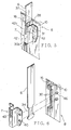
- Fig. 6 shows another embodiment of the present invention.
- the fixing member 7 is fixed to the base plate 10 of the protector body 8 by means of fusible projections 46 in a short columnar shape which are integrally formed on the base plate 10 made of synthetic resin. After the projections 46 have been inserted into the holes 40 in the fixing member 7, tip ends of the projections 46 may be pressed and deformed with a hot press or the like, or fused by means of a laser, so that the fixing member 7 can be fixed to the protector body 8.
- the slit 50 communicates with the space 53 and is positioned in a center of the space 53.
- a back face of the base plate 49 is opposed to a bottom of the space 53, and an upper end 49a of the base plate 49 is exposed by a width of the space 53 at an upper inlet 50a of the slit 50.
Landscapes
- Engineering & Computer Science (AREA)
- Mechanical Engineering (AREA)
- Installation Of Indoor Wiring (AREA)
- Details Of Indoor Wiring (AREA)
- Electric Cable Arrangement Between Relatively Moving Parts (AREA)
Abstract
Description
- The present invention relates to a structure for absorbing a slack of a wire harness which is installed in order to supply electric power from a vehicle body to a sliding door or the like in an automobile, and more particularly to the structure for absorbing the harness slack accompanying opening and closing movements of the sliding door, by pressing the wire harness by means of a plate-like resilient member, wherein fixation of the resilient member can be easily and reliably conducted.
- Heretofore, various apparatuses have been proposed in order to supply power, signals, etc. to a sliding door which is used in a one boxed car or on a rear seat side in a type of a passenger car, at any time irrespective of opening and closing movements of the sliding door.
- Conventionally, a slack of an electric wire accompanying opening and closing movements of the sliding door has been absorbed, for example, by curling the electric wire, or by installing a plurality of electric wires (wire harness) along a pair of link arms so that the pair of the link arms can be bent and stretched with the opening and closing movements of the sliding door.
- In case of the one boxed car, the wire harness including a power supply line is installed from the vehicle body side by way of a back of a step or its vicinity, extending from a lower part of the sliding door to an inside of the sliding door, and connected to various functional components in the sliding door, such as a power window motor, speaker, door lock unit, switch unit, etc.
- When the sliding door is opened by sliding it backward, the sliding door is slid backward while moving outwardly away from the vehicle body, and a gap is created between the sliding door and the vehicle body. As the door side wire harness moves backward integrally with the sliding door, a large slack will occur in the wire harness with respect to the vehicle body. In order to absorb this slack, there is a need for the aforesaid slack absorbing apparatus. In case where the slack is not absorbed, there may be arisen such a danger that the wire harness may be caught between the sliding door and the vehicle body and damaged when the sliding door is closed.
- As the sliding door is closed by sliding it forward, the door side wire harness is moved forward integrally with the sliding door and brought into a tensioned state.
- However, in the conventional apparatus as described above, employment of the link arms, for example, would lead to problems such as a complicated structure and a bulky size. It has been concerned that this may incur high component cost and increased number in steps for assembling the apparatus to the sliding door, and that flexibility in arranging the functional components in the sliding door may be limited.
- There has been also such an anxiety that, when the sliding door is closed violently, for example, the wire harness is pulled strongly and tends to be disengaged from the slack absorbing apparatus such as the link arms and so on. If the wire harness is disengaged, the slack of the wire harness will not be absorbed, and such an inconvenience that the wire harness may be caught between the sliding door and the vehicle body will occur.
- In view of the above described circumstances, the object of the present invention is to provide a harness slack absorbing structure which is simple in structure and can be assembled easily and reliably, and free from such a fear that the wire harness may be disengaged from the slack absorbing structure, even though the sliding door is violently closed.
- In order to achieve the above described object, there is provided, according to a first aspect of the present invention, a harness slack absorbing structure comprising a resilient member in a plate-like shape whose base end is fixed to a mounting part by means of a fixing member, and a wire harness installed along the resilient member, the resilient member being provided with a cut-out, the fixing member being provided with a slit to be engaged with the resilient member, wherein one end of the cut-out is abutted against a lower end of the slit, while the other end of the cut-out is abutted against a base end of the fixing member.
- According to a second aspect of the present invention, the cut-out is provided on either side or both sides in a lateral direction of the resilient member.
- According to a third aspect of the present invention, the mounting part includes an insertion part for receiving the resilient member, the insertion part being provided with a cut-out to be engaged with the fixing member.
- According to a fourth aspect of the present invention, the fixing member is fixed to the mounting part by screw means.
- According to a fifth aspect of the present invention, the fixing member is fixed to the mounting part through thermal deformation of projections which are formed of synthetic resin and provided on either of the mounting part and the fixing member.
- According to a sixth aspect of the present invention, the mounting part includes a protector for receiving the wire harness in a curved state, the protector being provided in a sliding door or a vehicle body.
- According to the first aspect, because the fixing member is fixed to the mounting part in a state where the plate-like resilient member has entered in the slit in the fixing member, the resilient member is held by inner edges of the slit in a direction of its thickness, and can be firmly supported without a backlash against bending force in a direction of the thickness of the resilient member. As the results, there will be no risk of rattle of the resilient member, disengagement of the resilient member from the mounting part, and wear of the mounting part due to repeated bending. Moreover, a length of the cut-out in the resilient member can be shorter by the length of the slit. This will enhance rigidity, bending strength, and tensile strength of the resilient member, and tear or plastic deformation of the resilient member due to the repeated contraction and expansion will be reliably prevented.
- Further, abutting the one end of the cut-out against the lower end of the slit will block a movement of the resilient member toward its base end, and abutting the other end of the cut-out against the base end of the fixing member will block a movement of the resilient member toward its distal end in a longitudinal direction. Because the resilient member is fixed in this manner so as not to move in a longitudinal direction, withdrawal of the resilient member when bent or pulled can be reliably prevented. Accordingly, reliable absorption of a slack of the wire harness can be always attained, and an inconvenience such as a bite of the wire harness can be eliminated.
- Further, because the harness slack absorbing apparatus is composed of a few components such as the plate-like resilient member and the fixing member, this will contribute to a simple structure, light weight, low cost, and facilitated assembling work.
- According to the second aspect, in case where the cut-outs are provided on both sides of the resilient member, the plate-like resilient member can be engaged with the slit in the fixing member, irrespective of a front face and a back face of the resilient member, thus enhancing assembling workability.
- According to the third aspect, by inserting the resilient member into the insertion part, the resilient member will be supported in a direction of the thickness resisting the bending force, and firmly held in cooperation with the supporting force of the aforesaid slit. Moreover, by engaging the fixing member with the cut-out in the insertion part in a state where the resilient member is engaged with the slit, the distal end of the fixing member is abutted against the one end of the cut-out in the insertion part, and the base end of the fixing member is abutted against the other end of the cut-out, enabling the resilient member to be firmly held in the insertion part resisting a tensile force in a longitudinal direction.
- According to the fourth aspect, the fixing member is firmly fixed to the mounting part by the screw means in a state where the resilient member is held by the fixing member and the fixing member is held by the insertion part. As the results, even though a strong tensile force or bending force is exerted on the resilient member, the resilient member will be reliably prevented from being disengaged from the mounting part, and reliable absorption of a slack of the wire harness can be always attained.
- According to the fifth aspect, by thermally deforming the projections made of synthetic resin, the fixing member can be simply and effectively fixed to the mounting part. At the same time, the component cost will be decreased and the fixing structure will be simplified, because the components such as small screws need not be employed.
- According to the sixth aspect, the insertion part, the fixing member and the resilient member can be safely protected inside the protector from interference with the exterior. Moreover, a slack of the wire harness occurring with opening and closing movements of the sliding door can be absorbed by the resilient member inside the protector, and a catch of the wire harness between the sliding door and the vehicle body and accompanying damage of the wire harness will be prevented.
-
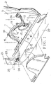
- Fig. 1 is an exploded perspective view showing an embodiment of a harness slack absorbing apparatus including a harness slack absorbing structure according to the present invention;
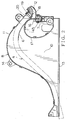
- Fig. 2 is a front view of the harness slack absorbing apparatus of Fig. 1;
- Fig. 3 is an exploded perspective view showing an embodiment of the harness slack absorbing structure according to the present invention;
- Fig. 4A is a plan view of a fixing member for a leaf spring;
- Fig. 4B is a front view of the fixing member of Fig. 4A;
- Fig. 5 is a perspective view of the harness slack absorbing structure in an assembled state;
- Fig. 6 is an exploded perspective view showing another embodiment of the harness slack absorbing structure according to the present invention; and
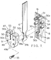
- Fig. 7 is an exploded perspective view showing still another embodiment of the harness slack absorbing structure according to the present invention.
-
- Now, preferred embodiments of the present invention will be described in detail referring to the attached drawings.
- A harness slack absorbing apparatus 1 is mounted on an
inner panel 3 of a slidingdoor 2, and includes a protector 5 made of synthetic resin and containing a door side wire harness 4 in a curved state, aleaf spring 6 which is a plate-like resilient member provided inside the protector 5 for upwardly pressing the wire harness 4, and afixing member 7 for fixing a base end of theresilient member 6 to the protector 5 . Thefixing member 7 constitutes an essential part of the present invention. - The protector 5 is composed of a
protector body 8 and a cover 9 as seen in Fig. 1. The cover 9 is detachably mounted on theprotector body 8 with locking means which are not shown. Theprotector body 8 is generally composed of avertical base plate 10 extending along theinner panel 3, a surroundingwall 11 in a curved shape uprightly provided on an upper and front sides of thebase plate 10, a firstharness guide outlet 12 provided at a forward end of the surroundingwall 11, and a secondharness guide outlet 13 which opens in a longitudinal direction below the surroundingwall 11. - The protector body 5 is fixed to the
door panel 3 by means of abolt 15 passed through anouter bracket 14 as shown in Fig. 1, or by other appropriate means. Aninsertion part 16 for receiving theresilient member 6 is formed in the base plate 10 (See Fig. 2). A base end of theresilient member 6 is fixed to theinsertion part 16 bymeans of thefixing member 7 . While an upper face of theresilient member 6 is pressed to a lower face of the wire harness 4 and theresilient member 6 extends backward along the lower face of the wire harness, the wire harness 4 is curved inside the protector 5 integrally with theresilient member 6. A distal end of theresilient member 6 is positioned under the wire harness 4 near an apex of the curve. - In the present embodiment, in order to prevent the
resilient member 6 and the wire harness 4 from being bent too much, aflexure restraining wall 17 in a loop shape is provided below theresilient member 6 . There is also provided aharness fixing part 18 near the firstharness guide outlet 12, as shown in Fig. 2. By engaging a projectingrib 19 of theharness fixing part 18 with a groove in acorrugated tube 20 surrounding the wire harness 4 and made of synthetic resin, the wire harness 4 is fixed so as not to move in a longitudinal direction. - As shown in Fig. 1, a backward portion of the wire harness 4 is guided out of the second
harness guide outlet 13 below the protector 5, and connected to a vehiclebody wire harness 25 via aconnector 24 which is fixed on a verticalback end wall 23 of astep 22 of avehicle body 21. A forward portion of the wire harness 4 is guided upwardly from the firstharness guide outlet 12 and connected to functional components (not shown) inside the slidingdoor 2 via aconnector 26. - In Fig. 1, the sliding
door 2 is in a closed position, and the wire harness 4 is pulled backward, while theresilient member 6 is pressed downward by the wire harness 4 to be flexed in a curved shape. Although the wire harness 4 tends to be slackened with opening movement of the slidingdoor 2, theresilient member 6 pushes the wire harness 4 upward to absorb the slack. In this manner, a catch of the wire harness 4 while the slidingdoor 2 is closed will be avoided. When the slidingdoor 2 is fully open, the protector 5 is positioned backward of theback end wall 23 of thestep 22, and the wire harness 4 is pulled forward against the pressure of theresilient member 6 contracting in diameter into a loop shape. Theresilient member 6 also contracts in diameter integrally with the wire harness 4. It is to be noted that the "forward and backward" directions in the description correspond to the front and the rear of the vehicle. - When the sliding
door 2 is opened or closed, a tension in a longitudinal direction, i.e., withdrawing force is exerted on theresilient member 6 following the contraction of the wire harness 4. However, theresilient member 6 will not be disengaged from the protector 5, because theresilient member 6 is firmly fixed by the aforesaid fixingmember 7. - Referring to Figs. 3 and 4, an embodiment of the fixing
member 7 will be described in detail. In Fig. 3, there are shown theinsertion part 16 integrally provided on thebase plate 10 of theprotector body 8, theresilient member 6, and the fixingmember 7 which is made of metal. - The
insertion part 16 is composed of a pair ofvertical walls 28 projected in a right angle from thebase plate 10 which is made of synthetic resin, aninsertion groove 29 formed between thewalls 28, and rectangular cut-outs 30 formed in both thewalls 28 at an intermediate position in a vertical direction. - A gap of the
insertion groove 29 has a slightly larger width than a thickness of theresilient member 6. Thewalls 28 are respectively provided withprojections 31 above the cut-outs 30, andlower edges 30a of the projections 31 (upper ends of the cut-outs 30) are in a horizontal position. In lower parts of the cut-outs 30, thewalls 28 extend rather longer, and theinsertion groove 29 is extended downward. Lower ends 30b of the cut-outs 30 are opposed to the upper ends 30a in parallel. Bottom ends 30c of the cut-outs 30 adjacent tonarrow portions 28a of thewalls 28 are vertically positioned. It is to be noted that a lower end of theinsertion groove 29 may be closed with a bottom wall (not shown). In this case, alower end 6a of theresilient member 6 may come into contact with the bottom wall of theinsertion groove 29 to be positioned in a longitudinal direction. - A pair of upper and lower holes (tap holes) 32 for fixing the fixing
member 7 to thebase plate 10 are provided on each side of the cut-outs 30. In this embodiment, an area of thebase plate 10 opposed to the fixingmember 7 is formed to have a larger thickness for the purpose of securing screwing strokes forsmall screws 33. - In a base end portion of the
resilient member 6, there are formed a pair of rectangular cut-outs 34 which are shorter in a vertical direction than the cut-outs 30 in theinsertion part 16, symmetrically on both sides thereof. Upper ends 34a and lower ends 34b of the cut-outs 34 are opposed in parallel and positioned horizontally. Bottom ends 34c of the cut-outs 34 are positioned vertically, and anarrow part 35 is formed between both the cut-outs 34. A depth of the cut-out 34 is smaller than a width of thenarrow part 35. Aprojection 36 is formed below the cut-outs 34, and a lower part of theprojection 36 is tapered at 36a for preventing an interference when inserted. An area above the cut-outs 34 is continued to abroad part 37. - By providing the cut-
outs 34 at both sides, it will be unnecessary to confirm the front and the back of theresilient member 6 in assembling, and the assembling work will be facilitated. In case where only one cut-out 34 is formed at one side, the side having the cut-out 34 must be opposed to thevehicle body 21 or the cover 9 in Fig. 1, when assembling, and the work would be annoying. In addition, by forming the vertical length of the cut-outs 34 smaller than that of the cut-outs 30 of theinsertion part 16, thenarrow part 35 has become shorter in length, thus increasing mechanical strength against tension or flexure of theresilient member 6. Accordingly, a risk of break down, fatigue failure, or plastic deformation of theresilient member 6 will be eliminated. - The fixing
member 7 is produced by stamping a metal plate with a press and by bending it into a bracket shape. As shown in Figs. 4A and 4B, a projectedpart 38 in a substantially U-shape in cross section is formed in a center part.Base plate parts 39 are integrally formed on both sides of the projectedpart 38 to be fixed to thebase plate 10 of theprotector body 8. There are formedholes 40 corresponding to theholes 32 for inserting the small screws. - The projected
part 38 includes on both sides thereofrectangular walls 41 which are opposed to each other, and acentral wall 42 connecting both thewalls 41, as shown in Fig. 4A. At a center of an upper half portion of the connectingwall 42, there is formed in a vertical direction astraight slit 43 which is adapted to be engaged with theresilient member 6. - As shown in Fig. 4A, a space 45 for receiving the base end of the
resilient member 6 and theinsertion part 16 of theprotector body 8 is defined inside the projectedpart 38. Theslit 43 has a length of substantially a half of a vertical length of the projectedpart 38 and a width slightly larger than a thickness of theresilient member 6, enabling theresilient member 6 to be firmly held without a backlash in a direction of the thickness of theresilient member 6. An inlet 43a at an upper end of theslit 43 is provided withchamfered parts 44 for guiding insertion of the leaf spring (See Fig. 4B). - A
lower end 43b of theslit 43 is adapted to get in contact with theupper end 34a of the cut-out 34 of theresilient member 6. A distance from thelower end 43b of theslit 43 to alower end 42b of the connectingwall 42 is slightly shorter than a vertical length of the cut-out 34 of theresilient member 6. In a state where theupper end 34a of the cut-out 34 of theresilient member 6 is abutted against thelower end 43b of theslit 43, it is possible to bring thelower end 34b of the cut-out 34, in other words, the upper edge of theprojection 36 of theresilient member 6 into contact with thelower end 42b of the connectingwall 42. A vertical length of the connectingwall 42 is slightly shorter than a length of the cut-outs 30 of theinsertion part 16, and the connectingwall 42 can be engaged in the cut-outs 30. - As shown in Fig. 5, one side portion of the
broad part 37 of theresilient member 6 above the cut-outs 34 enters into theslit 43 of the fixingmember 7. On this occasion, theupper end 34a of the cut-out 34 is abutted against thelower end 43b of theslit 43, that is, an intermediate position of the connectingwall 42, and at the same time, thelower end 34b of the cut-out 34 is abutted against thelower end 42b of the connectingwall 42. While theresilient member 6 is inserted into theinsertion part 16 of theprotector body 8 and the connectingwall 42 of the fixingmember 7 enters in the cut-outs 30 of theinsertion part 16, anupper end 42a of the connectingwall 42 is abutted against the upper ends 30a of the cut-outs 30, that is, the lower end faces of theupper projections 31, and thelower end 42b of the connectingwall 42 is abutted against the lower ends 30b of the cut-outs 30. - In this state, a pair of the
base plate parts 39 of the fixingmember 7 are fastened to thebase plate 10 of theprotector body 8 by means of thesmall screws 33 or bolts. Theholes 32 in the protector body need not be threaded, and thesmall screws 33 or the bolts are forcibly screwed into theholes 32. - As a first step for assembling, the cut-out 34 of the
resilient member 6 is engaged with the fixingmember 7, then, the fixingmember 7 is engaged with the cut-outs 30 in theinsertion part 16 of theprotector body 8, and finally, the fixingmember 7 is fixed to thebase plate 10 by means of the screws. In an alternative way, theresilient member 6 is inserted into theinsertion groove 29 in theinsertion part 16 as a first step, then the fixingmember 7 is engaged with the cut-out 34 of theresilient member 6 while the fixingmember 7 is being engaged with the cut-outs 30 in the insertion part, and finally the fixingmember 7 is fixed to thebase plate 10 by means of the screws. These assembling steps are the same in other embodiments as will be described below. - In case where the
insertion groove 29 has a bottom (not shown) to be abutted against alower end 6a of theresilient member 6, the latter step is advantageous. On the other hand, in case where theinsertion groove 29 is bottomless, the former step is advantageous. Particularly, because theslit 43 is provided in the fixingmember 7, either step can be employed for assembling. - In Fig. 5, the
resilient member 6 is preferably supported by thewalls 28 including theprojections 31 in the upper part of theinsertion part 16 along its substantially entire width, and thus, theresilient member 6 will be smoothly flexed without torsion, resulting in an enhanced supporting strength of theinsertion part 16. Even though fixing strength of the fixingmember 7 by means of thescrews 33 is rather weak, theprojections 31 will strengthen the support of theresilient member 6, and the screws will be prevented from being loosen. - By engaging the
broad part 37 of theresilient member 6 in theslit 43 of the fixingmember 7, theresilient member 6 can be supported by both side areas or one of theside areas 42c of theslit 43 in a direction of thickness of theresilient member 6, and accordingly, in cooperation with the support by theinsertion part 16, the supporting strength of theresilient member 6 will be further increased. Theinsertion part 16 made of synthetic resin will be thus prevented from deformation or breakage. The lower ends 30b of the cut-outs 30 in theinsertion part 16 are useful for positioning the fixingmember 7 when the fixingmember 7 is fixed to theprotector body 8, and assembling workability will be enhanced. Abutment of thelower end 42b of the fixingmember 7 against the lower ends 30b of the cut-outs 30 will increase the supporting strength of the fixingmember 7, and the fixingmember 7 can fully withstand a pressure when theresilient member 6 expands from the flexed state enlarging its diameter. - Moreover, a vertical length of the cut-out 34 of the
resilient member 6 can be decreased by provision of theslit 43 in the fixingmember 7, as compared with a case where theslit 43 is not provided. As the results, rigidity, spring force and bending strength of theresilient member 6 will be increased, and tear or plastic deformation of the resilient member starting from the cut-outs 34 due to repeated use will be prevented. - The wire harness 4 (See Fig. 2) is arranged along a front face of the
broad part 37 of theresilient member 6 in Fig. 5. Because the base end of theresilient member 6 has been rigidly fixed to theprotector body 8, there will be no need of a cumbersome work that the base end of theresilient member 6 must be attached to the wire harness 4 which is round or oval in cross section to fix the resilient member, and thus, the assembling work will be facilitated. Moreover, once the base end of theresilient member 6 has been fixed, the wire harness 4 can be easily extended along theresilient member 6, and accordingly, such a work as fixing the wire harness 4 to the distal end of theresilient member 6 by means of a tape or band, for example, can be easily conducted. - Further, even when the wire harness 4 is strongly tightened at the opening and closing movements of the sliding
door 2 and theresilient member 6 is subjected to a strong force in a tensile direction through friction against the wire harness 4, a withdrawal of theresilient member 6 will be prevented, because the base end of theresilient member 6 has been rigidly fixed. Accordingly, absorption of a slack of the wire harness 4 can be reliably performed, and a bite of the wire harness 4 between the slidingdoor 2 and thevehicle body 21 can be reliably prevented. - In Fig. 3, the bolts may be inserted into the
holes 32 from a back of thebase plate 10 and passed through theholes 40 in the fixingmember 7 to be fastened by means of nuts (not shown) in front of the fixingmember 7, or alternatively, the bolts may be screwed into weld nuts (not shown) provided on the fixingmember 7 and fastened. - Fig. 6 shows another embodiment of the present invention. In this embodiment, the fixing
member 7 is fixed to thebase plate 10 of theprotector body 8 by means offusible projections 46 in a short columnar shape which are integrally formed on thebase plate 10 made of synthetic resin. After theprojections 46 have been inserted into theholes 40 in the fixingmember 7, tip ends of theprojections 46 may be pressed and deformed with a hot press or the like, or fused by means of a laser, so that the fixingmember 7 can be fixed to theprotector body 8. - A plurality of the
projections 46 can be crushed and deformed at a time with the hot press or the like. - Alternatively, the tip ends of the
projections 46 may be integrally provided with locking clips or hooks (not shown) , with which the fixingmember 7 can be detachably locked. - By employing such fixing methods and structures, cost for components such as the small screws and bolts can be saved, and cumbersome screwing works will be unnecessary. Thus, the structure will be simplified and the cost will be reduced. In addition, as compared with the embodiment in Fig. 3, the
base plate 10 of theprotector body 8 can be thin-walled, because a heavy screwing stroke is not required, and therefore, the structure can be made compact and light-weighted. - In Fig. 6, the structure except the
projections 46 is the same as in Fig. 3, and so, the same elements are denoted with the same reference numerals and their explanation will be omitted. - Fig. 7 shows still another embodiment of the present invention. In this embodiment, a fixing
member 47 is formed of synthetic resin. The fixingmember 47 is fixed to thecylindrical projections 48 of theprotector body 8 by screw fitting. Theresilient member 6 and the insertion part of theprotector body 8 are the same as in the embodiment of Fig. 3, and denoted with the same reference numerals. - The fixing
member 47 is molded by means of resin forming molds (not shown) . The fixingmember 47 is composed of afront base plate 49, aslit 50 formed in a center of an upper half area of thebase plate 49 and adapted to be engaged with theresilient member 6, fixingholes 51 provided in thebase plate 49 in both side areas of theslit 50, and a pair of solid box-like parts 52 which are integrally formed in rear of thebase plate 49. Theholes 51 pass through the box-like parts 52. - There is formed a
space 53 in a shape of a groove between a pair of the box-like parts 52 in such a manner that theinsertion part 16 of theprotector body 8 can be inserted therein. Theslit 50 communicates with thespace 53 and is positioned in a center of thespace 53. A back face of thebase plate 49 is opposed to a bottom of thespace 53, and anupper end 49a of thebase plate 49 is exposed by a width of thespace 53 at anupper inlet 50a of theslit 50. - One side of the
resilient member 6 is inserted into theslit 50 in such a manner that theupper end 34a of the cut-out 34 of theresilient member 6 is abutted against alower end 50b of theslit 50 and thelower end 34b of the cut-out 34 is abutted against alower end 49b of thebase plate 49. In this manner, theresilient member 6 is positioned with respect to the fixingmember 47, and the position of theresilient member 6 both in a longitudinal direction and in a direction of its thickness can be determined. - In the box-
like parts 52 in the back, there are formed spaces (not shown) for receivingcylindrical projections 48 of theprotector body 8. A depth of the box-like parts 52 is equal to a length of theprojections 48. Two each of theprojections 48 are arranged on both sides of the cut-outs 30 in thewalls 28 of theinsertion part 16. An inner diameter of thecylindrical projection 48 is smaller than an outer diameter of threads of screw means such as thesmall screw 33 or bolt so that thesmall screw 33 may be forcibly screwed into abore 54 inside theprojection 48. - Screwing of the small screws is conducted, after the
resilient member 6 has been inserted into theinsertion part 16 and the position of theresilient member 6 has been determined by the fixingmember 47, in a state where thebase plate 49 of the fixingmember 47 has been engaged with the cut-outs 30 in theinsertion part 16. Because theupper end 49a of thebase plate 49, that is, both side areas of theinlet 50a of theslit 50 is abutted against the upper ends 30a of the cut-outs 30, that is, the lower edges of theupper projections 31, and thelower end 49b of thebase plate 49 is abutted against a stepped part, that is, the lower ends 30b of the cut-outs 30, the fixingmember 47 can be positioned with respect to theprotector body 8. On the other hand, it is also possible to fix the fixingmember 47 to theprotector body 8 by screw fitting, by first engaging theresilient member 6 with the fixingmember 47, and then, engaging the fixingmember 47 with the cut-outs 30 in the insertion part. - By engaging the fixing
member 47 carrying theresilient member 6 fixed thereto, with the cut-outs 30 in the insertion part, the fixingmember 47 can be firmly fixed to the protector body 8.against tensile force and bending force of theresilient member 6. Moreover, because theprojections 48 for the screws are projected so as to get in contact with the back face of thebase plate 49, screw tightening strength, in other words, fixing strength of the fixingmember 47 can be enhanced. - In place of the
cylindrical projections 48, the columnarsolid projections 46 as shown in Fig. 6 may be provided so as to pass through theholes 51 in the fixingmember 47, and the tip ends of theprojections 46 may be thermally deformed to fix the fixingmember 47 to theprotector body 8. Alternatively, thecylindrical projections 48 may be provided on the back face of thebase plate 49 or the box-like parts 52 of the fixingmember 47, and the small screws may be screwed from the back face of thebase plate 10 of theprotector body 8. It is also possible to form the fixingmember 7 in a substantially same shape as in Fig. 3 by resin molding, and to pass thesmall screws 33 through theholes 40 to directly screw them into theholes 32 in theprotector body 8. - Further, the fixing
member 7 may be inclined backward or forward in Fig. 2, so that theslit 43 may be positioned in an inclined manner backward or forward instead of vertically. Still further, theresilient member 6 may be composed of not only a sheet of leaf spring but also two sheets of the leaf springs piled on each other. Alternatively, the two sheets of the leaf springs may be arranged above and below the wire harness 4. Only the base end of theresilient member 6 may be in a plate-like shape, while the distal end portion and the intermediate portion of theresilient member 6 may be in a rod-like shape. - Referring to Fig. 3, if the cut-out 34 is formed up to a half of the width of the
resilient member 6, the center part of theresilient member 6 but not one side only can be engaged in theslit 43 of the fixingmember 7. In this manner, theresilient member 6 can be supported without torsion even though theupper projections 31 of theinsertion part 16 are not provided. - It is also possible to arrange the protector 5 horizontally in the
vehicle body 21, for example, under thestep 22, but not on the slidingdoor 2. Further, the protector 5 may be composed of theprotector body 8 only, and a door trim (not shown) or the doorinner panel 3 may be used in place of the cover 9. - Although the present invention has been fully described by way of examples with reference to the accompanying drawings, it is to be noted that various changes and modifications can be made within the scope of the present invention.
Claims (6)
- A harness slack absorbing structure comprising a resilient member in a plate-like shape whose base end is fixed to a mounting part by means of a fixing member, and a wire harness installed along said resilient member, said resilient member being provided with a cut-out,
said fixing member being provided with a slit for engagement with said resilient member,
wherein one end of said cut-out is abutted against a lower end of said slit, while the other end of said cut-out is abutted against a base end of said fixing member. - The harness slack absorbing structure as claimed in claim 1, wherein said cut-out is provided on either side or both sides in a lateral direction of said resilient member.
- The harness slack absorbing structure as claimed in claim 1 or 2, wherein said mounting part includes an insertion part for receiving said resilient member, said insertion part being provided with a cut-out for engagement with said fixing member.
- The harness slack absorbing structure as claimed in any one of claims 1 to 3, wherein said fixing member is fixed to said mounting part by screw means.
- The harness slack absorbing structure as claimed in any one of claims 1 to 3, wherein said fixing member is fixed to said mounting part through thermal deformation of projections which are formed of synthetic resin and provided on either of said mounting part and said fixing member.
- The harness slack absorbing structure as claimed in any one of claims 1 to 5, wherein said mounting part includes a protector for receiving said wire harness in a curved state, said protector being provided in a sliding door or a vehicle body.
Applications Claiming Priority (2)
| Application Number | Priority Date | Filing Date | Title |
|---|---|---|---|
| JP2001076514A JP2002281650A (en) | 2001-03-16 | 2001-03-16 | Harness slack absorbing structure |
| JP2001076514 | 2001-03-16 |
Publications (2)
| Publication Number | Publication Date |
|---|---|
| EP1241057A1 true EP1241057A1 (en) | 2002-09-18 |
| EP1241057B1 EP1241057B1 (en) | 2004-06-02 |
Family
ID=18933430
Family Applications (1)
| Application Number | Title | Priority Date | Filing Date |
|---|---|---|---|
| EP02005880A Expired - Lifetime EP1241057B1 (en) | 2001-03-16 | 2002-03-14 | Harness slack holding apparatus for sliding car doors |
Country Status (4)
| Country | Link |
|---|---|
| US (1) | US6566603B2 (en) |
| EP (1) | EP1241057B1 (en) |
| JP (1) | JP2002281650A (en) |
| DE (1) | DE60200561D1 (en) |
Cited By (3)
| Publication number | Priority date | Publication date | Assignee | Title |
|---|---|---|---|---|
| GB2380619B (en) * | 2001-08-07 | 2005-05-18 | Yazaki Corp | Feeder assembly of car sliding door |
| EP2236360A4 (en) * | 2008-01-29 | 2012-11-28 | Autonetworks Technologies Ltd | CABLE TREE FOR AN AUTOMOTIVE |
| EP2503657A4 (en) * | 2009-11-20 | 2013-04-10 | Aisin Seiki | Wiring holding structure |
Families Citing this family (19)
| Publication number | Priority date | Publication date | Assignee | Title |
|---|---|---|---|---|
| CZ20032254A3 (en) * | 2001-02-20 | 2003-12-17 | Malgorzata Wesolowska | Skirting board with finishing elements |
| JP2003189451A (en) * | 2001-12-11 | 2003-07-04 | Yazaki Corp | Harness slack absorbing device |
| JP4098615B2 (en) * | 2002-05-20 | 2008-06-11 | 矢崎総業株式会社 | Power supply device for slide structure |
| US7087839B2 (en) * | 2002-07-11 | 2006-08-08 | Yazaki North America, Inc. | Slack-based method for determining wire harness tolerance |
| JP2005137082A (en) * | 2003-10-29 | 2005-05-26 | Yazaki Corp | Constant power supply device |
| JP4681988B2 (en) * | 2005-05-16 | 2011-05-11 | 矢崎総業株式会社 | Constant power supply device |
| JP2006327328A (en) * | 2005-05-24 | 2006-12-07 | Honda Motor Co Ltd | Harness wiring structure |
| JP4722580B2 (en) * | 2005-06-24 | 2011-07-13 | 矢崎総業株式会社 | Clamp structure |
| JP2007181268A (en) * | 2005-12-27 | 2007-07-12 | Yazaki Corp | Power feeding device for slide structure |
| KR100720687B1 (en) * | 2005-12-28 | 2007-05-21 | 주식회사 세원이씨에스 | Wiring protector for automobile |
| JP5012063B2 (en) * | 2007-02-05 | 2012-08-29 | 住友電装株式会社 | Wiring harness wiring structure for automobile |
| DE102007017286A1 (en) * | 2007-04-12 | 2008-10-16 | Leoni Bordnetz-Systeme Gmbh | Cable guide |
| JP5182569B2 (en) * | 2007-12-27 | 2013-04-17 | 株式会社リコー | Image forming apparatus |
| JP5386126B2 (en) * | 2008-08-19 | 2014-01-15 | 矢崎総業株式会社 | Wire harness |
| JP5308889B2 (en) * | 2009-03-30 | 2013-10-09 | 矢崎総業株式会社 | Power feeding device for slide structure |
| JP2013018322A (en) * | 2011-07-08 | 2013-01-31 | Sumitomo Wiring Syst Ltd | Wire harness routing structure part |
| US8723039B2 (en) * | 2012-03-27 | 2014-05-13 | Toyota Motor Engineering & Manufacturing North America, Inc. | Wire harness with slack absorption |
| CN110783033A (en) * | 2018-01-19 | 2020-02-11 | 熊帅 | Anti-tensile common wire with LINE-X coating |
| JP2020078169A (en) * | 2018-11-07 | 2020-05-21 | 矢崎総業株式会社 | Cabling structure |
Citations (4)
| Publication number | Priority date | Publication date | Assignee | Title |
|---|---|---|---|---|
| FR2616390A1 (en) * | 1987-06-12 | 1988-12-16 | Peugeot | Structure for mounting an electric wiring harness for a door |
| EP0855312A2 (en) * | 1996-12-25 | 1998-07-29 | Sumitomo Wiring Systems, Ltd. | A wiring harness arranging construction |
| US20010052203A1 (en) * | 2000-04-11 | 2001-12-20 | Kenichi Doshita | Power supply structure in sliding structure |
| US20020014348A1 (en) * | 2000-06-30 | 2002-02-07 | Tohru Aoki | Structure of installing wire harness for sliding door |
Family Cites Families (5)
| Publication number | Priority date | Publication date | Assignee | Title |
|---|---|---|---|---|
| US4974798A (en) * | 1989-12-18 | 1990-12-04 | Chrysler Corporation | Vehicle wiring harness cable mounting assembly structure |
| US5466036A (en) * | 1994-05-09 | 1995-11-14 | Chrylser Corporation | Vehicle wire routing apparatus |
| JP3183170B2 (en) * | 1996-06-14 | 2001-07-03 | 住友電装株式会社 | Wire harness wiring structure in the door hinge part of the car |
| JP3191914B2 (en) * | 1996-07-05 | 2001-07-23 | 矢崎総業株式会社 | Vehicle door harness assembly structure |
| JP3351501B2 (en) * | 1996-09-04 | 2002-11-25 | 矢崎総業株式会社 | Telescopic structure of door circuit |
-
2001
- 2001-03-16 JP JP2001076514A patent/JP2002281650A/en not_active Abandoned
-
2002
- 2002-03-14 EP EP02005880A patent/EP1241057B1/en not_active Expired - Lifetime
- 2002-03-14 US US10/096,941 patent/US6566603B2/en not_active Expired - Fee Related
- 2002-03-14 DE DE60200561T patent/DE60200561D1/en not_active Expired - Lifetime
Patent Citations (4)
| Publication number | Priority date | Publication date | Assignee | Title |
|---|---|---|---|---|
| FR2616390A1 (en) * | 1987-06-12 | 1988-12-16 | Peugeot | Structure for mounting an electric wiring harness for a door |
| EP0855312A2 (en) * | 1996-12-25 | 1998-07-29 | Sumitomo Wiring Systems, Ltd. | A wiring harness arranging construction |
| US20010052203A1 (en) * | 2000-04-11 | 2001-12-20 | Kenichi Doshita | Power supply structure in sliding structure |
| US20020014348A1 (en) * | 2000-06-30 | 2002-02-07 | Tohru Aoki | Structure of installing wire harness for sliding door |
Cited By (4)
| Publication number | Priority date | Publication date | Assignee | Title |
|---|---|---|---|---|
| GB2380619B (en) * | 2001-08-07 | 2005-05-18 | Yazaki Corp | Feeder assembly of car sliding door |
| EP2236360A4 (en) * | 2008-01-29 | 2012-11-28 | Autonetworks Technologies Ltd | CABLE TREE FOR AN AUTOMOTIVE |
| EP2503657A4 (en) * | 2009-11-20 | 2013-04-10 | Aisin Seiki | Wiring holding structure |
| US8901423B2 (en) | 2009-11-20 | 2014-12-02 | Aisin Seiki Kabushiki Kaisha | Wiring holding structure for vehicle sliding door |
Also Published As
| Publication number | Publication date |
|---|---|
| US20020129963A1 (en) | 2002-09-19 |
| US6566603B2 (en) | 2003-05-20 |
| DE60200561D1 (en) | 2004-07-08 |
| JP2002281650A (en) | 2002-09-27 |
| EP1241057B1 (en) | 2004-06-02 |
Similar Documents
| Publication | Publication Date | Title |
|---|---|---|
| EP1241057B1 (en) | Harness slack holding apparatus for sliding car doors | |
| EP1241056B1 (en) | Harness slack holding apparatus for sliding car doors | |
| US7297871B2 (en) | Electric supply apparatus | |
| US6070931A (en) | Assembly structure of an automotive door harness | |
| US7420125B2 (en) | Grommet assembly | |
| US6698808B2 (en) | Motor vehicle bumper and motor vehicle | |
| GB2365632A (en) | Wire harness slack absorbing mechanism for vehicular sliding door | |
| US7364201B2 (en) | Vehicle occupant restraint system | |
| CN105358352A (en) | Sliding window for vehicle, and trim board fixing method | |
| JP5299699B2 (en) | Electrical junction box | |
| US7057109B2 (en) | Guide protector for harness, wire-excessive portion absorbing structure therewith, and fixing method of guide protector for harness | |
| JP2007506877A (en) | Deviation device for automobile window lift device | |
| US4753467A (en) | Movable molding for a vehicle | |
| JP5422997B2 (en) | Vehicle door opening and closing device | |
| JP3949432B2 (en) | Harness slack absorber | |
| US8011696B2 (en) | Bent pre-tensioner tube | |
| EP3124299B1 (en) | Sunroof apparatus | |
| US6890211B2 (en) | Connector holding structure | |
| US7037025B2 (en) | Attaching device for fuel tank band | |
| JP2008189226A (en) | Power supply device | |
| KR20080024941A (en) | Assembly unit for moving the belt buckle with the vehicle seat | |
| US20040045734A1 (en) | Structure for attaching a harness protector used in supplying electricity | |
| US5882032A (en) | Attachment device for securing a gas bag module to a vehicle part | |
| JPH10329644A (en) | Vertical regulator for vehicle safety belt flexible appointment | |
| JP4372647B2 (en) | Rear camera mounting structure |
Legal Events
| Date | Code | Title | Description |
|---|---|---|---|
| PUAI | Public reference made under article 153(3) epc to a published international application that has entered the european phase |
Free format text: ORIGINAL CODE: 0009012 |
|
| AK | Designated contracting states |
Kind code of ref document: A1 Designated state(s): AT BE CH CY DE DK ES FI FR GB GR IE IT LI LU MC NL PT SE TR |
|
| AX | Request for extension of the european patent |
Free format text: AL;LT;LV;MK;RO;SI |
|
| 17P | Request for examination filed |
Effective date: 20021217 |
|
| AKX | Designation fees paid |
Designated state(s): DE FR GB IT |
|
| GRAP | Despatch of communication of intention to grant a patent |
Free format text: ORIGINAL CODE: EPIDOSNIGR1 |
|
| GRAS | Grant fee paid |
Free format text: ORIGINAL CODE: EPIDOSNIGR3 |
|
| GRAA | (expected) grant |
Free format text: ORIGINAL CODE: 0009210 |
|
| AK | Designated contracting states |
Kind code of ref document: B1 Designated state(s): DE FR GB IT |
|
| PG25 | Lapsed in a contracting state [announced via postgrant information from national office to epo] |
Ref country code: IT Free format text: LAPSE BECAUSE OF FAILURE TO SUBMIT A TRANSLATION OF THE DESCRIPTION OR TO PAY THE FEE WITHIN THE PRESCRIBED TIME-LIMIT;WARNING: LAPSES OF ITALIAN PATENTS WITH EFFECTIVE DATE BEFORE 2007 MAY HAVE OCCURRED AT ANY TIME BEFORE 2007. THE CORRECT EFFECTIVE DATE MAY BE DIFFERENT FROM THE ONE RECORDED. Effective date: 20040602 |
|
| REG | Reference to a national code |
Ref country code: GB Ref legal event code: FG4D |
|
| REF | Corresponds to: |
Ref document number: 60200561 Country of ref document: DE Date of ref document: 20040708 Kind code of ref document: P |
|
| REG | Reference to a national code |
Ref country code: IE Ref legal event code: FG4D |
|
| PG25 | Lapsed in a contracting state [announced via postgrant information from national office to epo] |
Ref country code: DE Free format text: LAPSE BECAUSE OF FAILURE TO SUBMIT A TRANSLATION OF THE DESCRIPTION OR TO PAY THE FEE WITHIN THE PRESCRIBED TIME-LIMIT Effective date: 20040903 |
|
| ET | Fr: translation filed | ||
| PLBE | No opposition filed within time limit |
Free format text: ORIGINAL CODE: 0009261 |
|
| STAA | Information on the status of an ep patent application or granted ep patent |
Free format text: STATUS: NO OPPOSITION FILED WITHIN TIME LIMIT |
|
| 26N | No opposition filed |
Effective date: 20050303 |
|
| PG25 | Lapsed in a contracting state [announced via postgrant information from national office to epo] |
Ref country code: GB Free format text: LAPSE BECAUSE OF NON-PAYMENT OF DUE FEES Effective date: 20060314 |
|
| GBPC | Gb: european patent ceased through non-payment of renewal fee |
Effective date: 20060314 |
|
| PGFP | Annual fee paid to national office [announced via postgrant information from national office to epo] |
Ref country code: FR Payment date: 20070308 Year of fee payment: 6 |
|
| REG | Reference to a national code |
Ref country code: FR Ref legal event code: ST Effective date: 20081125 |
|
| PG25 | Lapsed in a contracting state [announced via postgrant information from national office to epo] |
Ref country code: FR Free format text: LAPSE BECAUSE OF NON-PAYMENT OF DUE FEES Effective date: 20080331 |