EP1240402B1 - Einrichtung zur signalerkennung mit adaptiver filtertechnik in der druckpulstelemetrie - Google Patents
Einrichtung zur signalerkennung mit adaptiver filtertechnik in der druckpulstelemetrie Download PDFInfo
- Publication number
- EP1240402B1 EP1240402B1 EP00992691A EP00992691A EP1240402B1 EP 1240402 B1 EP1240402 B1 EP 1240402B1 EP 00992691 A EP00992691 A EP 00992691A EP 00992691 A EP00992691 A EP 00992691A EP 1240402 B1 EP1240402 B1 EP 1240402B1
- Authority
- EP
- European Patent Office
- Prior art keywords
- signal
- primary
- pulse
- anc
- transducer
- Prior art date
- Legal status (The legal status is an assumption and is not a legal conclusion. Google has not performed a legal analysis and makes no representation as to the accuracy of the status listed.)
- Expired - Lifetime
Links
Images



Classifications
-
- E—FIXED CONSTRUCTIONS
- E21—EARTH OR ROCK DRILLING; MINING
- E21B—EARTH OR ROCK DRILLING; OBTAINING OIL, GAS, WATER, SOLUBLE OR MELTABLE MATERIALS OR A SLURRY OF MINERALS FROM WELLS
- E21B47/00—Survey of boreholes or wells
- E21B47/12—Means for transmitting measuring-signals or control signals from the well to the surface, or from the surface to the well, e.g. for logging while drilling
- E21B47/14—Means for transmitting measuring-signals or control signals from the well to the surface, or from the surface to the well, e.g. for logging while drilling using acoustic waves
- E21B47/18—Means for transmitting measuring-signals or control signals from the well to the surface, or from the surface to the well, e.g. for logging while drilling using acoustic waves through the well fluid, e.g. mud pressure pulse telemetry
Definitions
- the present invention generally relates to a method of processing mud pulse telemetry and, more specifically, to a method of analyzing mud pulse telemetry signals using adaptive noise cancellation techniques.
- Typical petroleum drilling operations employ a number of techniques to gather information such as the size and direction of a bore hole and the types of materials through which a drillpipe and drill bit are drilling.
- This technique or “wireline logging,” is expensive in terms of both money and time; so techniques called Measurement-While-Drilling (MWD) and Logging-While-Drilling (LWD) were developed.
- LWD collects the same type of information as wireline logging while MWD also enables a driller to determine the direction of a bore hole during the drilling operation so that the driller can more accurately control the drilling operations.
- the techniques of the disclosed embodiment apply to both MWD and LWD and, for the purpose of the disclosed embodiment, they will be referred to together as "MWD/LWD.”
- a problem common to MWD/LWD is how to transmit data from the bottom of a bore hole to a point on the surface where it can be collected and processed.
- a typical technique for this type of data transmission is mud pulse telemetry. During the drilling operation, drilling mud is pumped from a mud pump downward through the drillpipe and emerges near the drill bit at the bottom of the drill hole. This mud cools and lubricates the drill bit, carries rock cuttings to the surface where they can be analyzed and prevents the walls of the bore hole from collapsing.
- a transmission device such as an electo-mechanical pulser or a mud siren near the drill bit generates a signal that is transmitted upward to the surface through the downward traveling column of mud.
- a transducer typically at the surface, receives the signal and transmits it to a signal processor.
- the signal processor then decodes and analyzes the signal to provide real-time information about the drilling operation to the driller.
- noise seen by the transducer generated by the drilling operation, obscures the signal.
- noise may be introduced by the turning of the drill bit and drillpipe and/or from the mud pump used to force the mud into the drillpipe.
- Another source of noise is a reflected signal that is created when the original signal hits a pulsation dampener, or "desurger", near the top of the mud column and is reflected back down the hole.
- the MWD/LWD signal may he degraded by the type of mud, the mud pressure, the length and joints of the drillpipe, and the desurger.
- GB 2147722 discloses a method and apparatus for receiving and processing telemetry data that passes through the drill string of a borehole drilling rig from a MWD apparatus in the drill string.
- the signal receiving apparatus includes a pair of spaced detectors in a mud flow conduit between the mud circulating pump and the drill string.
- US 5969638 discloses a MWD system featuring a signal processor for use with a plurality of transducers.
- US 2787759 discloses a method and apparatus for logging the formation characteristics of a well borehole which utilizes the drilling fluid circulating stream as a signal transmission medium.
- US4,243,935 discloses an adaptive detector comprising an adaptive linear prediction filter and a detection processor.
- the present invention relates to a method of detecting telemetry in drilling fluid during drilling operation as set forth in claim 1 comprising the steps of: detecting at a primary transducer a combination of an upstream travelling drilling fluid pressure pulse, the transmitted pulse, and a reflected pulse corresponding to the transmitted pulse after being reflected at a reflection point upstream from the primary transducer and producing a primary signal based upon the detected combination of the transmitted pulse and the detected reflected pulse; detecting the transmitted pulse at a reference transducer positioned at or near the reflection point and producing a secondary signal based upon the detected transmitted pulse; and generating an adaptive noise canceller (ANC) output signal based upon a difference between the primary signal and the secondary signal.
- ANC adaptive noise canceller
- the present invention also relates to A Measurement-While-Drilling/Logging-While-Drilling (MWD/LWD) system as set forth in claim 7 comprising:
- the signal at a second transducer is subtracted from the signal at a first transducer.
- the first transducer is placed such that a leading edge of an upward traveling signal can be sampled before a downward traveling signal caused by the reflection of the upward traveling signal arrives at the first transducer.
- the second transducer is placed either close to or at the point where the upward traveling signal is reflected and thus is, in essence, the upward traveling signal uncontaminated by the downward traveling reflected signal.
- One or both of the signals received at the first transducer and the second transducer are time shifted, and the second signal is then subtracted from the first signal.
- This technique produces a processed signal with more sharply defined leading and trailing edges. Because the information carried by a signal is typically encoded either in the pulse position or the timing and the phase of the signal, more sharply defined leading and trailing edges enable the processed signal to be less obscured by the noise and more easily decoded than a signal in a single-transducer MWD/LWD system.
- a mud pulse telemetry adaptive noise canceller is provided to process Measure-While-Drilling/Logging-While-Drilling (MWD/LWD) communication signals to provide information on down hole conditions during a MWD/LWD drilling operation.
- the ANC employs two transducers, each receiving a succession of signals.
- a primary transducer located down hole from both a mud pump and a desurger, receives a primary signal.
- a reference transducer located near or, optimally, on the desurger, receives a reference signal.
- the ANC calculates a best least squares fit between the reference signal and the correlated primary signal and then estimates the phase and magnitude of linearly correlated parts of the MWD/LWD data.
- the ANC employs a transversal filter structure, or Finite Impulse Response (FIR) filter, in conjunction with a set of coefficients, or weights, calculated or updated continuously in real-time to improve the behaviour or performance of the ANC according to desired criteria.
- FIR Finite Impulse Response
- the ANC of the disclosed embodiment determines the phase and amplitude of linearly related counterparts in corresponding primary and reference signals and uses this phase and amplitude information to process a successive signal.
- a successive signal is either a primary or reference signal that follows the primary and reference signal, either immediately or later.
- the successive signal is the reference signal; but, in the alternative, the successive signal may be a primary signal.
- the ANC may also calculate a set of coefficients based upon a finite number of primary and reference signals and then employ this fixed set of coefficients on successive signals.
- the disclosed ANC can actively adapt to changing conditions in a bore hole such as variations in depth and the materials through which a drillpipe and a drill bit are passing.
- the techniques of the disclosed embodiment enhance data transmission in a variety of noise environments by automatically adjusting in real time to changes in the pressure signal or to noise sources that may be present due to changing drilling conditions.
- the ANC output contains a sharply defined peak at a leading edge of output pulses of the ANC output and a sharply defined dip at a trailing edge of the output pulses with a frequency that is dependent on the distance between the two transducers.
- the generated spikes are time synchronized with the transmitted modulated pulses, thus providing accurate clock tracking and recovery, more reliable signal detection, a better S/N ratio and thus higher data transmission rates.
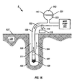
- FIG. 1a shows an exemplary single-transducer, Measurement-While-Drilling/Logging-While-Drilling (MWD/LWD) system S for processing MWD/LWD telemetry.
- a mud pump 101 generates a downward-travelling mud flow 103 through a drillpipe, or annulus, 105.
- the rotation of the drillpipe 105 and a drill bit 109 connected to the drillpipe 105 creates a bore hole 125 in the earth 129.
- the mud flow 103 emerges from the drill bit 109 into the bore hole 125 and creates an upward-travelling mud flow 104 through an annulus 126, or the space between the drillpipe 105 and the edge of the bore hole 125.
- a transmission device 107 such as an electo-mechanical pulser or a mud siren, produces an acoustic or pressure wave, or "signal" 111 that travels at the speed of sound in mud towards the earth's surface 127 through the downward-travelling mud flow 103 in the drillpipe 105 and is received or detected at a transducer 113.
- the transducer 113 is connected to a signal processor 115 that decodes and analyzes the signal 111.
- the signal 111 is encoded using pulse position and carries information about drilling parameters and conditions in the drill hole 125 that a driller may use to monitor and control the drilling operation.
- the signal 111 may instead be encoded using phase and amplitude and the signal 111 may instead be transmitted through and received from the upward travelling mud flow 104 in the annulus 126.
- MWD/LWD system S Also included in MWD/LWD system S is a desurger 117 that evens out the mud flow 103 within the drillpipe 105.
- a membrane 121 separates the desurger 117 into a mud section 123 and a nitrogen section 119.
- the desurger 117 acts like an accumulator to smooth outlet pressure generated by the mud pump 101.
- the computing system C includes a bus controller 22, a processor 14, synchronous dynamic access memory (SDRAM) 11, an analog-to-digital (A/D) converter 18, a digital signal processing module (DSP) 16 and a memory 12.
- SDRAM synchronous dynamic access memory
- A/D analog-to-digital
- DSP digital signal processing module
- the memory 12 is non-volatile memory such as a hard disk drive or an EEPROM device.
- the processor 14, the SDRAM 11, the memory 12, the DSP 16 and the bus controller are coupled to a bus 20.
- the computer system C is controlled by an operating system (OS) (not shown) which is stored in one or both of the memory 12 and the SRAM 11 and executes on the processor 14.
- OS operating system
- a primary pressure transducer 163 and a reference pressure transducer 165 are coupled to the A/D converter 18, which is coupled to the DSP 16. Both the primary transducer 163 and the reference transducer 165 are described in more detail below in conjunction with Figure 4 .
- the computing system C is a processor-based device programmed to implement the techniques of the disclosed embodiment.
- Computer code to implement an adaptive noise canceller (ANC) of the disclosed embodiment is stored in one or both the memory 12 and the SRAM 11 and executed on the processor 14 or the DSP 16.
- ANC adaptive noise canceller
- the computing system C may be a personal computer (PC) with a video display and a keyboard enabling human interaction with the computing system C.
- PC personal computer
- a specific processor, operating system, memory, bus and certain other hardware and software components are not critical to the techniques of the disclosed embodiments and are used as examples only.
- the techniques of the disclosed embodiment may be incorporated into hard-wired electronic circuits.
- the MWD/LWD system T includes a mud pump 151, a drillpipe 157, a mud flow 155 produced by the mud pump 151 through the drillpipe 157, a desurger 153 and a transmission device 158 that are similar in type and function to the mud pump 101, the drillpipe 105, the mud flow 103, the desurger 117, and the transmission device 107 respectively of the single-transducer, MWD/LWD system S ( Fig 1a ).
- the MWD/LWD system T includes two transducers, the primary pressure transducer 163, located upstream of the pulser (not shown) and downstream of the desurger 153, and the reference pressure transducer 165, located near or, optimally, on the desurger 153. Both the primary transducer 163 and the reference transducer 165 were first introduced above in conjunction with Figure 1b .
- the primary transducer 163 should be between 50 and 300 feel from the desurger 153; and the reference transducer 165 should be near or on the desurger 153.
- the primary transducer 163 can also be termed the rig floor transducer 163.
- the primary transducer 163 receives a transmitted signal 167, which is generated by the transmission device 158, and a reflected signal 169. It should be understood that both the transmitted signal 167 and the reflected signal 169 contain MWD/LWD data.
- the reflected signal 169 is created when the transmitted signal 167 reflects from the desurger 153 and is propagated back down hole in the same direction as the mud flow 155.
- the characteristics of a signal received at the transducers 163 and 165 differ due to the relative positions of the transducers 163 and 165, the mud pump 151 and the desurger 153.
- the signal received at the primary transducer 163 includes both the transmitted pulse 167 and the reflected pulse 169: the signal received at the reference transducer 165 includes the transmitted pulse 167 only due to the reference transducer's 165 location either near or on the desurger 153.
- the techniques of the invention take advantage of the difference between the signal received at the primary transducer 163 and the signal received at the reference transducer 165 to facilitate the processing of the transmitted signal 167.
- Suitable pressure transducers that may serve as the primary and reference transducers 163 and 165 are the Gerns 6100 manufactured by Gens Sensors, Inc. of Plainville, Conneticut; the Dynisco PT386 or PT390 manufactured by Dynisco, Inc. of Sharon, Massachuttes; and the Viatran 709, 571 or 70 series manufactured by the Viatran Corporation of Grand Island, New York.
- the specific transducer employed is not critical to the techniques of the disclosed embodiment but should preferably have a response time of 20 ms or less.
- the primary transducer 163 converts the received, combined pressure pulses 167 and 169 into a primary electrical signal 400
- the reference transducer 165 converts the received pressure pulse 167 into a secondary electrical signal 402.
- the primary transducer 163 and the reference transducer 165 provide the primary signal 400 and the reference signal 402 respectively to a signal conditioning box 175.
- the signal conditioning box 175 provides an anti-aliased primary signal 404 and an anti-aliased secondary signal 406 respectively to a primary channel 177 and secondary channel 179 respectively of an adaptive noise canceller (ANC) 181.
- ANC adaptive noise canceller
- the ANC 181 is described in more detail in Figure 4
- the primary transducer 163 is preferably placed between 50 and 300 feet from and downstream of the desurger 153; and the reference transducer 165 is within 20 feet downstream of or, optimally, on the desurger 153.
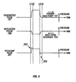
- the first pressure pulse is the transmitted pulse 167 that travels through the downward traveling mud flow 155 ( Fig 2 ) in an upstream direction, or toward the mud pump 151.
- the second pressure pulse is the reflected pulse 169 that travels in a downstream direction, or away form the desurger 153.
- the reflected pulse 169 is created when the transmitted pulse 167 reaches the desurger 153 and is reflected back down hole.
- the transmitted pulse 167 begins at a time t1 and ends at a time t3.
- the reflected pulse 169 begins at a time t2 and ends at a time t4 and has less amplitude then the transmitted pulse 167.
- the difference in amplitude between the transmitted pulse 167 and the reflected pulse 169 can be attributed to the attenuation of the transmitted pulse 167 as it travels upstream, energy lost when the transmitted pulse 167 is reflected by the desurger 153, and the attenuation in the resulting reflected pulse 169 as it travels back downstream.
- the difference between the beginning of the transmitted pulse at time t1 and the beginning of the reflected pulse 169 at time t2 represents an amount of travel time it takes for the transmitted pulse 167 to travel upstream from the primary transducer 163 to the desurger 153, become the reflected pulse 169, and travel back downstream to the primary transducer 163.
- the difference between the end of the transmitted pulse 167 at time t3 and the end of the reflected pulse 169 at t4 represents approximately the same travel time.
- the third exemplary pulse is a resultant pulse 201 that represents the sum of the transmitted pulse 167 and the reflected pulse 169.
- the reflected pulse 169 arrives at the primary transducer 163 later than the transmitted pulse 167 and is of a smaller magnitude.
- the resultant pulse 201 has a peak 203 at the beginning edge.
- the resultant pulse 201 also has a dip 205 at the trailing edge.
- the reference transducer 165 receives the transmitted pulse 167 and, because it is either near or on the desurger 153, almost none of the reflected pulse 169.
- the techniques of the disclosed embodiment employ the resultant pulse 201 received at the reference transducer 165, as well as data from the processing of preceding pulses, to process the transmitted pulse 167.
- the sharp edges of the resultant pulse 201 have a frequency that is dependant on the distance between the primary and reference transducers 163 and 165 and are highly correlated with the rising and falling edges of the transmitted and reflected pulses 167 and 169.
- the sharp edges are time synchronized with the transmitted pulse 167, thus providing accurate clock tracking and recovery, greater signal amplitude and a better S/N ratio, leading to more reliable signal detection and higher transmission rates.
- the resultant pulse 201 is more sharply defined than the transmitted pulse 167 or the reflected pulse 169, and MWD/LWD data can be transmitted at higher data rates than in either a single transducer MWD/LWD system or in a two-transducer MWD/LWD system that does not employ an ANC 181.
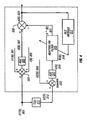
- a summer 331 represents the combination of the s1(k) signal 303, the n1(k) signal 301 and the r(k) signal 305 to form the d(k) signal 307 and does not necessarily represent a physical device.
- the d(k) signal 307 is processed by an automatic gain control (AGC) device 325, which adjusts the d(k) signal 307 to a level appropriate for further processing, and is then passed to a summer 335. described in more detail below.
- AGC automatic gain control
- the sl(k) signal 303 goes through a T(z) transformation 311 which produces a s2(k) signal 313.
- the T(z) transformation 311 represents a physical conversion of the s1(k) signal 303 from a current loop into voltage for data acquisition cards (not shown) of the computing system C ( Fig 1b ) and, in the disclosed embodiment, includes anti-aliasing filtering.
- the T(z) transformation 311 also represents a physical transformation of the s1(k) signal 303 such as effects caused by the length of and number of joints in the drillpipe 157.
- a secondary input signal n(k) 319 which corresponds to the reference signal 402 ( Fig. 2 ), is the output of a summer 333, which combines the output of the T(z) transformation 311, or a s2(k) signal 313, and a n2(k) noise signal 309 that represents electronic/random noise such as that introduced by the A/D converter 18.
- the summer 333 does not necessarily represent a physical device.
- the n(k) signal 319 is passed by the summer 333 to an AGC device 327, which adjusts the level of the n(k) signal 319 to a level appropriate for further processing, and then to an adaptive tapped delay line finite impulse response (FIR) filter 315, which is described in more detail below.
- the reference signal n(k) 319 is "weighted" by the FIR filter 315 using a set of coefficients W(k) 318.
- the coefficients W(k) 318 are calculated by means of a recursive least squares (RLS) module 317, described in more detail below.
- the output of the FIR filter 315 is a weighted n(k) signal 319, or a n ⁇ (k) signal 321.
- the n ⁇ (k) signal 321 is subtracted from the primary signal d(k) to give an estimate of the ANC output, e(k).
- the calculation of e(k) is done in such a way as to minimize the expected square value of e(k).
- the s2'(k) signal (not shown) and the n2'(k) signal (not shown) represent the individual weighting of the s2(k) signal and the n2(k) signal respectively.
- n ⁇ (k) signal 321 is subtracted from the primary input signal d(k) 307 by the summer 335 to give an estimate of an ANC error signal e(k), or an ANC output signal, 323.
- n k n ⁇ 1 k + r k - s ⁇ 2 ⁇ ⁇ k .
- the W(k) coefficients 318 are calculated using a RLS-type algorithm by the RLS module 317 based upon an e(k) signal 323 corresponding to previous transmitted pulses. Since E ⁇ s(k) 2 ⁇ is constant, minimization of the error square E ⁇ e(k) 2 ⁇ reduces to a minimum squared error cancellation of sr(k) by W(k)*n(k).
- the W(k) coefficients 318 are adjusted to minimize the mean square value of the e(k) signal 323.
- the equation directly above represents a basic mean square error (MSE) algorithm or what basically is referred to as a Least Mean Square (LMS) algorithm for adjusting or updating the FIR filter 315 coefficients, which represent the phase and magnitude of linearly correlated counter parts of the primary signal d(k) 307 and the reference signal n(k) 319.
- MSE mean square error
- LMS Least Mean Square
- the RLS module 317 of the disclosed embodiment uses an RLS-type algorithm based on a least square approach that processes the received data to minimize a quadratic performance index.
- Minimization of the quadratic performance index provides a "fit" between the primary signal d(k) 307 and the reference signal (n(k) 319.
- This least square algorithm is known to those with knowledge in the art as the RLS, or Kalman, algorithm. Variations of the RLS, or Kalman, algorithm such as the Fast Recursive Least Square algorithm may also be used to calculate and adjust the W(k) coefficients 318. It should be understood that other algorithms derived or related to the RLS algorithm (i.e. RLS-type algorithms) can be used.
- the FIR filter 315 output, n ⁇ (k) 321, is then subtracted from the primary input signal d(k) 307 by the summer 335 to obtain the e(k) signal 323 which is passed then for further processing.
- the ANC 181 is used to isolate spike frequencies and remove signal interference that might have resulted due to the drilling process and is common to both the primary signal 163 and the reference signal 165.
- FIG. 5 illustrated is a timing diagram that includes an exemplary transmitted pulse 501 similar to the transmitted pulse 167 ( Fig. 3 ) and an exemplary ANC output pulse 503.
- pressure is plotted as a function of time.
- the ANC output pulse 503 includes a peak 505 at the leading edge and a dip 507 at the trailing edge.
- the peak 505 and the dip 507 are more pronounced than the peak 203 and the dip 205, respectively.
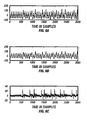
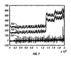
- Figures 6 and 7 are diagrams showing additional exemplary inputs and outputs of the ANC 181 of the disclosed embodiment plotted in terms of pressure as a function of time.
- a primary input signal 307 and a reference input signal 319 are processed by the ANC 181 ( Fig. 2 ) to produce a ANC output signal 401.
- Figure 7 shows an exemplary dual-channel MWD/LWD system.
- a primary input signal 703 and a reference signal 705 are processed by the ANC 181 to produce a ANC output signal 707.
- the ANC output signal 707 also includes sharply defined peaks and dips. Use of such an ANC output signal allows for reliable recovery of MWD/LWD data.
Landscapes
- Engineering & Computer Science (AREA)
- Physics & Mathematics (AREA)
- Life Sciences & Earth Sciences (AREA)
- Mining & Mineral Resources (AREA)
- Geology (AREA)
- Geophysics (AREA)
- Environmental & Geological Engineering (AREA)
- Fluid Mechanics (AREA)
- Remote Sensing (AREA)
- Acoustics & Sound (AREA)
- General Life Sciences & Earth Sciences (AREA)
- Geochemistry & Mineralogy (AREA)
- Arrangements For Transmission Of Measured Signals (AREA)
- Measuring Pulse, Heart Rate, Blood Pressure Or Blood Flow (AREA)
- Earth Drilling (AREA)
- Measuring Fluid Pressure (AREA)
- Radar Systems Or Details Thereof (AREA)
- Networks Using Active Elements (AREA)
Claims (16)
- Verfahren zum Erfassen der Telemetrie in einem Bohrfluid während Bohrvorgängen, umfassend folgende Schritte:Erfassen an einem primären Wandler (163) einer Kombination aus einem sich stromaufwärts ausbreitenden Bohrfluiddruckimpulses, des gesendeten Impulses (167) und eines reflektierten Impulses (169) entsprechend dem gesendeten Impuls nach der Reflexion an einem Reflexionspunkt (153) stromaufwärts von dem primären Wandler (163) und Erzeugen eines primären Signals auf der Basis der erfassten Kombination aus dem gesendetern Impuls und dem erfassten reflektierten Impuls;Erfassen des gesendeten Impulses an einem Bezugswandler (165), der im wesentlichen an dem Reflexionspunkt angeordnet ist, und Erzeugen eines sekundären Signals auf der Basis des erfassten gesendeten Impulses (167) und Erzeugen eines Ausgangssignals eines adaptiven Rauschunterdrückers (ANC) auf der Basis eines Unterschiedes zwischen dem primären Signal und dem sekundären Signal.
- Verfahren nach Anspruch 1, bei dem das ANC-Ausgangssignal einen ANC-Ausgangsimpuls mit einer scharf definierten Spitze an der Anstiegsflanke des ANC-Ausgangsimpulses und einem scharf definierten Abfall an der Abstiegsflanke des ANC-Ausgangsimpulses enthält.
- Verfahren nach einem der vorhergehenden Ansprüche, bei dem ein nachfolgendes Signal ebenfalls auf der Basis eines Unterschiedes zwischen einem vorherigen primären Signal an dem primären Wandler und einem vorherigen sekundären Signal an dem Bezugswandler abgeändert wird.
- Verfahren nach einem der vorhergehenden Ansprüche, bei dem der ANC-Ausgangssignal-Erzeugungsschritt folgenden Schritt umfasst:adaptives Unterdrücken des Rauschens korrelierender Abschnitte zwischen dem primären Signal und dem sekundären Signal durch Berechnen einer Übereinstimmung zwischen dem primären Signal und dem sekundären Signal, um das ANC-Ausgangssignal auf der Basis nicht korrelierender Abschnitte zwischen dem primären Signal und dem sekundären Signal zu erzeugen.
- Verfahren nach Anspruch 4, bei dem der ANC-Ausgangssignal-Erzeugungsschritt umfasst:Berechnen eines Satzes von Gewichtungskoeffzienten auf der Basis der Übereinstimmung; undErzeugen des ANC-Ausgangssignals auf der Basis des Satzes von Gewichtungskoeffizienten.
- Verfahren nach Anspruch 5, bei dem die Gewichtungskoeffizienten mit Hilfe eines Algorithmus' des kleinsten quadratischen Fehlers oder mit Hilfe eines Algorithmus' des rekursiven kleinsten quadratischen Fehlers (RLS) berechnet werden.
- System mit kontinuierlicher Aufnahme des Bohrverlaufs / kontinuierlicher Aufzeichnung des Bohrverlaufs (MWD/LWD), enthaltend:i) einen primären Wandler (163);ii) einen Bezugswandler (165), der im wesentlichen an einem Reflexionspunkt stromaufwärts von der Position des primären Wandlers angeordnet ist;iii) einem adaptiven Rauschunterdrücker (ANC), enthaltend ein Modul für den kleinsten quadratischen Fehler (RLS), um eine Übereinstimmung auf der Basis eines Unterschiedes zwischen einem primären Signal, das einer Kombination aus dem gesendeten Impuls und einem reflektierten Impuls entspricht, der an dem primären Wandler erfasst wird, und einem sekundären Signal, das dem gesendeten Impuls entspricht, der am Bezugswandler erfasst wird; undein Filter für adaptives finites Impulsansprechverhalten (FIR), um ein ANC-Ausgangssignal auf der Basis des Unterschiedes zwischen dem primären Signal und dem sekundären Signal zu erzeugen.
- MWD/LWD-System nach Anspruch 7, bei dem die Übereinstimmung zudem auf einer Übereinstimmung zwischen einem Unterschied zwischen einem vorherigen primären Signal, das einem zuvor gesendeten Impuls entspricht, und einem vorherigen sekundären Signal basiert, das dem zuvor gesendeten Impuls entspricht.
- MWD/LWD-System nach einem der Ansprüche 7 oder 8, bei dem das ANC-Ausgangssignal enthält:einen ANC-Ausgangsimpuls mit einer scharf definierten Spitze an einer Anstiegsflanke des ANC-Ausgangsimpulses undeinem scharf definierten Abfall an einer Abstiegsflanke des ANC-Ausgangsimpulses.
- MWD/LWD-System nach einem der Ansprüche 7 bis 9, weiterhin enthaltend:eine Gewichtungskoeffizienten-Erzeugungslogik, die einen Satz von Gewichtungskoeffizienten auf der Basis der Übereinstimmung zwischen dem primären Signal und dem sekundären Signal berechnet, die von dem RLS-Modul berechnet werden; undeine Gewichtungskoeffizienten-Anwendungslogik, die den Satz von Gewichtungskoeffizienten zur Erzeugung des ANC-Ausgangssignals durch das adaptive FIR-Filter anwendet.
- MWD/LWD-System nach Anspruch 10, bei dem der Satz der Gewichtungskoeffizienten auf der Phase und der Amplitude des primären Signals und des sekundären Signals basiert.
- MWD/LWD-System nach einem der Ansprüche 7 bis 11, bei dem die Übereinstimmung zwischen dem primären Signal und dem sekundären Signal auf der Übereinstimmung des kleinsten quadratischen Fehlers basiert, der vorzugsweise mit Hilfe eines Algorithmus' eines schnellen rekursiven kleinsten quadratischen Fehlers (RLS) berechnet wird.
- MWD/LWD-System nach einem der Ansprüche 7 bis 12, enthaltend einen Computer, der derart programmiert ist, dass er eine Übereinstimmung zwischen dem primären Signal und dem sekundären Signal berechnet, um eine lineare Beziehung zwischen einer ersten Vielzahl von Punkten des primären Signals und einer zweiten Vielzahl von Punkten des sekundären Signals zu erzeugen.
- MWD/LWD-System nach Anspruch 13, bei dem der Computer weiterhin dazu programmiert ist:Gewichtungskoeffizienten auf der Basis der Übereinstimmung zwischen dem primären Signal und dem sekundären Signal zu berechnen unddas ANC-Ausgangssignal auf der Basis der Gewichtungskoeffizienten zu justieren.
- MWD/LWD-System nach Anspruch 14, bei dem die Übereinstimmung zudem auf einer Übereinstimmung zwischen einem vorherigen primären Signal und einem entsprechenden vorherigen sekundären Signal basiert oder
die Übereinstimmung auf der Phase und der Amplitude des primären Signals und des sekundären Signals basiert. - MWD/LWD-System nach Anspruch 14 oder 15, bei dem die Berechnungen der Gewichtungskoeffizienten mit Hilfe eines Algorithmus' des kleinsten quadratischen Fehlers ausgeführt werden, wobei der Algorithmus vorzugsweise ein Algorithmus eines schnellen rekursiven kleinsten quadratischen Fehlers (RLS) ist.
Applications Claiming Priority (3)
| Application Number | Priority Date | Filing Date | Title |
|---|---|---|---|
| US469989 | 1995-06-06 | ||
| US09/469,989 US6308562B1 (en) | 1999-12-22 | 1999-12-22 | Technique for signal detection using adaptive filtering in mud pulse telemetry |
| PCT/US2000/042725 WO2001046548A2 (en) | 1999-12-22 | 2000-12-08 | Technique for signal detection using adaptive filtering in mud pulse telemetry |
Publications (3)
| Publication Number | Publication Date |
|---|---|
| EP1240402A2 EP1240402A2 (de) | 2002-09-18 |
| EP1240402A4 EP1240402A4 (de) | 2004-03-10 |
| EP1240402B1 true EP1240402B1 (de) | 2010-07-14 |
Family
ID=23865844
Family Applications (1)
| Application Number | Title | Priority Date | Filing Date |
|---|---|---|---|
| EP00992691A Expired - Lifetime EP1240402B1 (de) | 1999-12-22 | 2000-12-08 | Einrichtung zur signalerkennung mit adaptiver filtertechnik in der druckpulstelemetrie |
Country Status (10)
| Country | Link |
|---|---|
| US (1) | US6308562B1 (de) |
| EP (1) | EP1240402B1 (de) |
| AT (1) | ATE474125T1 (de) |
| AU (1) | AU4522601A (de) |
| BR (1) | BR0016630A (de) |
| CA (1) | CA2394076C (de) |
| DE (1) | DE60044681D1 (de) |
| MX (1) | MXPA02005781A (de) |
| NO (1) | NO323090B1 (de) |
| WO (1) | WO2001046548A2 (de) |
Cited By (1)
| Publication number | Priority date | Publication date | Assignee | Title |
|---|---|---|---|---|
| WO2023146541A1 (en) * | 2022-01-26 | 2023-08-03 | Halliburton Energy Services, Inc. | Noise reduction for downhole telemetry |
Families Citing this family (22)
| Publication number | Priority date | Publication date | Assignee | Title |
|---|---|---|---|---|
| GB2392762A (en) * | 2002-09-06 | 2004-03-10 | Schlumberger Holdings | Mud pump noise attenuation in a borehole telemetry system |
| GB2402308B (en) * | 2003-05-28 | 2006-01-04 | Nokia Corp | Par reduction for edge clipper |
| US7251566B2 (en) | 2005-03-31 | 2007-07-31 | Schlumberger Technology Corporation | Pump off measurements for quality control and wellbore stability prediction |
| US7489591B2 (en) * | 2005-05-06 | 2009-02-10 | Pathfinder Energy Services, Inc. | Drilling fluid pressure pulse detection using a differential transducer |
| US8004421B2 (en) * | 2006-05-10 | 2011-08-23 | Schlumberger Technology Corporation | Wellbore telemetry and noise cancellation systems and method for the same |
| US8629782B2 (en) | 2006-05-10 | 2014-01-14 | Schlumberger Technology Corporation | System and method for using dual telemetry |
| US7480207B2 (en) * | 2006-01-16 | 2009-01-20 | Halliburton Energy Services, Inc. | Filtering and detection of telemetry |
| BRPI0707834B1 (pt) * | 2006-02-14 | 2018-05-29 | Baker Hughes Incorporated | Sistema e método para cancelamento de ruído em telemetria de pulso na lama |
| US7557492B2 (en) | 2006-07-24 | 2009-07-07 | Halliburton Energy Services, Inc. | Thermal expansion matching for acoustic telemetry system |
| US7595737B2 (en) * | 2006-07-24 | 2009-09-29 | Halliburton Energy Services, Inc. | Shear coupled acoustic telemetry system |
| US7877211B2 (en) * | 2006-09-18 | 2011-01-25 | Schlumberger Technology Corporation | Downlink based on pump noise |
| US8811118B2 (en) | 2006-09-22 | 2014-08-19 | Baker Hughes Incorporated | Downhole noise cancellation in mud-pulse telemetry |
| US10061059B2 (en) * | 2007-07-13 | 2018-08-28 | Baker Hughes, A Ge Company, Llc | Noise cancellation in wellbore system |
| US8135058B2 (en) * | 2008-10-10 | 2012-03-13 | Csr Technology Inc. | Adaptive known signal canceller |
| US8730764B2 (en) | 2009-07-30 | 2014-05-20 | Schlumberger Technology Corporation | Telemetry coding and surface detection for a mud pulser |
| EP2592445B1 (de) | 2010-06-21 | 2018-05-30 | Halliburton Energy Services, Inc. | Druckimpulstelemetrie |
| RU2668099C1 (ru) * | 2014-12-10 | 2018-09-26 | Хэллибертон Энерджи Сервисиз, Инк. | Устройства и способы для фильтрации помех, обусловленных работой бурового насоса, при гидроимпульсной телеметрии |
| US9850754B1 (en) | 2016-06-17 | 2017-12-26 | Ge Energy Oilfield Technology, Inc. | High speed telemetry signal processing |
| CA2984296C (en) * | 2016-10-28 | 2025-09-23 | Pulse Directional Technologies Inc. | BOTTOM-HOLE DATA COMMUNICATION SYSTEMS AND METHODS |
| CN110346260B (zh) * | 2019-08-02 | 2022-03-08 | 东北石油大学 | 致密油储层基质岩心静态渗吸采收率激光测量装置及方法 |
| GB2603333B (en) * | 2019-08-28 | 2023-05-10 | Baker Hughes Oilfield Operations Llc | Mud pulse transmission time delay correction |
| US12234719B2 (en) * | 2020-07-30 | 2025-02-25 | Schlumberger Technology Corporation | Methods for determining a position of a droppable object in a wellbore |
Family Cites Families (25)
| Publication number | Priority date | Publication date | Assignee | Title |
|---|---|---|---|---|
| US2787759A (en) * | 1950-08-31 | 1957-04-02 | Jan J Arps | Apparatus for logging wells |
| US3908454A (en) * | 1972-10-12 | 1975-09-30 | Mobil Oil Corp | Method and apparatus for logging flow characteristics of a well |
| US4208906A (en) * | 1978-05-08 | 1980-06-24 | Interstate Electronics Corp. | Mud gas ratio and mud flow velocity sensor |
| US4243935A (en) * | 1979-05-18 | 1981-01-06 | The United States Of America As Represented By The Secretary Of The Navy | Adaptive detector |
| FR2457490A1 (fr) * | 1979-05-23 | 1980-12-19 | Elf Aquitaine | Procede et dispositif de detection in situ d'un fluide de gisement dans un trou de forage |
| US4295366A (en) * | 1979-05-29 | 1981-10-20 | A. C. Company | Drilling fluid circulating and monitoring system and method |
| US4299123A (en) * | 1979-10-15 | 1981-11-10 | Dowdy Felix A | Sonic gas detector for rotary drilling system |
| FR2530286B1 (fr) * | 1982-07-13 | 1985-09-27 | Elf Aquitaine | Procede et systeme de detection d'un fluide de gisement dans un puits de forage |
| US4733232A (en) * | 1983-06-23 | 1988-03-22 | Teleco Oilfield Services Inc. | Method and apparatus for borehole fluid influx detection |
| US4733233A (en) * | 1983-06-23 | 1988-03-22 | Teleco Oilfield Services Inc. | Method and apparatus for borehole fluid influx detection |
| US4532812A (en) * | 1983-06-30 | 1985-08-06 | Nl Industries, Inc. | Parametric acoustic flow meter |
| US4590593A (en) * | 1983-06-30 | 1986-05-20 | Nl Industries, Inc. | Electronic noise filtering system |
| CA1213666A (en) * | 1983-10-03 | 1986-11-04 | Gary D. Berkenkamp | Logging while drilling system signal recovery system |
| USH55H (en) * | 1984-06-18 | 1986-05-06 | Method for improved mud pulse telemetry | |
| US4733380A (en) * | 1984-12-26 | 1988-03-22 | Schlumberger Technology Corporation | Apparatus and method for acoustically investigating a casing set in a borehole |
| FR2627649B1 (fr) * | 1988-02-22 | 1990-10-26 | Inst Francais Du Petrole | Methode et dispositif de transmission de l'information par cable et par ondes de boue |
| US5274606A (en) * | 1988-04-21 | 1993-12-28 | Drumheller Douglas S | Circuit for echo and noise suppression of accoustic signals transmitted through a drill string |
| US4905203A (en) * | 1988-09-30 | 1990-02-27 | Texaco Inc. | Downhole doppler flowmeter |
| US4912683A (en) * | 1988-12-29 | 1990-03-27 | Atlantic Richfield Company | Method for acoustically measuring wall thickness of tubular goods |
| US4947683A (en) * | 1989-08-03 | 1990-08-14 | Halliburton Logging Services, Inc. | Pulsed ultrasonic doppler borehole fluid measuring apparatus |
| US5610815A (en) * | 1989-12-11 | 1997-03-11 | Caterpillar Inc. | Integrated vehicle positioning and navigation system, apparatus and method |
| US5386472A (en) * | 1990-08-10 | 1995-01-31 | General Motors Corporation | Active noise control system |
| US5832095A (en) * | 1996-10-18 | 1998-11-03 | Carrier Corporation | Noise canceling system |
| US5940519A (en) * | 1996-12-17 | 1999-08-17 | Texas Instruments Incorporated | Active noise control system and method for on-line feedback path modeling and on-line secondary path modeling |
| US5969638A (en) * | 1998-01-27 | 1999-10-19 | Halliburton Energy Services, Inc. | Multiple transducer MWD surface signal processing |
-
1999
- 1999-12-22 US US09/469,989 patent/US6308562B1/en not_active Expired - Lifetime
-
2000
- 2000-12-08 AT AT00992691T patent/ATE474125T1/de not_active IP Right Cessation
- 2000-12-08 AU AU45226/01A patent/AU4522601A/en not_active Abandoned
- 2000-12-08 DE DE60044681T patent/DE60044681D1/de not_active Expired - Lifetime
- 2000-12-08 BR BR0016630-8A patent/BR0016630A/pt not_active Application Discontinuation
- 2000-12-08 EP EP00992691A patent/EP1240402B1/de not_active Expired - Lifetime
- 2000-12-08 WO PCT/US2000/042725 patent/WO2001046548A2/en not_active Ceased
- 2000-12-08 MX MXPA02005781A patent/MXPA02005781A/es unknown
- 2000-12-08 CA CA002394076A patent/CA2394076C/en not_active Expired - Fee Related
-
2002
- 2002-06-04 NO NO20022632A patent/NO323090B1/no not_active IP Right Cessation
Cited By (1)
| Publication number | Priority date | Publication date | Assignee | Title |
|---|---|---|---|---|
| WO2023146541A1 (en) * | 2022-01-26 | 2023-08-03 | Halliburton Energy Services, Inc. | Noise reduction for downhole telemetry |
Also Published As
| Publication number | Publication date |
|---|---|
| WO2001046548A2 (en) | 2001-06-28 |
| DE60044681D1 (de) | 2010-08-26 |
| US6308562B1 (en) | 2001-10-30 |
| NO323090B1 (no) | 2007-01-02 |
| EP1240402A2 (de) | 2002-09-18 |
| BR0016630A (pt) | 2002-11-12 |
| NO20022632D0 (no) | 2002-06-04 |
| CA2394076A1 (en) | 2001-06-28 |
| ATE474125T1 (de) | 2010-07-15 |
| AU4522601A (en) | 2001-07-03 |
| EP1240402A4 (de) | 2004-03-10 |
| NO20022632L (no) | 2002-08-21 |
| CA2394076C (en) | 2007-03-13 |
| WO2001046548A9 (en) | 2002-08-15 |
| MXPA02005781A (es) | 2003-10-14 |
| WO2001046548A3 (en) | 2002-01-10 |
Similar Documents
| Publication | Publication Date | Title |
|---|---|---|
| US6308562B1 (en) | Technique for signal detection using adaptive filtering in mud pulse telemetry | |
| US10070204B2 (en) | Collaborative telemetry | |
| US8111171B2 (en) | Wellbore telemetry and noise cancellation systems and methods for the same | |
| US7940192B2 (en) | Channel equalization for mud-pulse telemetry | |
| US6151554A (en) | Method and apparatus for computing drill bit vibration power spectral density | |
| EP1334376B1 (de) | Adaptive filterung mit referenzsensor zur unterdrückung des gerätespezifischen störsignals in einer mwd messung | |
| US20070189119A1 (en) | System and Method for Measurement While Drilling Telemetry | |
| US5969638A (en) | Multiple transducer MWD surface signal processing | |
| US7453372B2 (en) | Identification of the channel frequency response using chirps and stepped frequencies | |
| JP2003155886A (ja) | ボアホール流体音響特性の自己較正超音波現場測定方法 | |
| WO2005043191A2 (en) | Directional acoustic telemetry receiver | |
| US20240376818A1 (en) | Movement noise suppression in a moving array for downhole leakage localization | |
| US11885218B2 (en) | Adaptive pulse waveform for channel estimation in mud pulse telemetry | |
| US20240069232A1 (en) | Evaluation of Density and Seismic Impedance Values of Geologic Layers using Drill Bit Sound during Drilling | |
| US11821306B2 (en) | Optimization of pulse generation parameters to compensate for channel non-linearity in mud pulse telemetry |
Legal Events
| Date | Code | Title | Description |
|---|---|---|---|
| PUAI | Public reference made under article 153(3) epc to a published international application that has entered the european phase |
Free format text: ORIGINAL CODE: 0009012 |
|
| 17P | Request for examination filed |
Effective date: 20020607 |
|
| AK | Designated contracting states |
Kind code of ref document: A2 Designated state(s): AT BE CH CY DE DK ES FI FR GB GR IE IT LI LU MC NL PT SE TR |
|
| AX | Request for extension of the european patent |
Free format text: AL;LT;LV;MK;RO;SI |
|
| RIC1 | Information provided on ipc code assigned before grant |
Free format text: 7G 01V 1/40 A |
|
| R17D | Deferred search report published (corrected) |
Effective date: 20020815 |
|
| RIC1 | Information provided on ipc code assigned before grant |
Ipc: 7G 01V 11/00 B Ipc: 7E 21B 47/18 A |
|
| A4 | Supplementary search report drawn up and despatched |
Effective date: 20040122 |
|
| 17Q | First examination report despatched |
Effective date: 20040817 |
|
| RAP1 | Party data changed (applicant data changed or rights of an application transferred) |
Owner name: SMITH INTERNATIONAL, INC. |
|
| GRAP | Despatch of communication of intention to grant a patent |
Free format text: ORIGINAL CODE: EPIDOSNIGR1 |
|
| GRAS | Grant fee paid |
Free format text: ORIGINAL CODE: EPIDOSNIGR3 |
|
| GRAA | (expected) grant |
Free format text: ORIGINAL CODE: 0009210 |
|
| AK | Designated contracting states |
Kind code of ref document: B1 Designated state(s): AT BE CH CY DE DK ES FI FR GB GR IE IT LI LU MC NL PT SE TR |
|
| REG | Reference to a national code |
Ref country code: GB Ref legal event code: FG4D |
|
| REG | Reference to a national code |
Ref country code: CH Ref legal event code: EP |
|
| REG | Reference to a national code |
Ref country code: IE Ref legal event code: FG4D |
|
| REF | Corresponds to: |
Ref document number: 60044681 Country of ref document: DE Date of ref document: 20100826 Kind code of ref document: P |
|
| REG | Reference to a national code |
Ref country code: NL Ref legal event code: VDEP Effective date: 20100714 |
|
| PG25 | Lapsed in a contracting state [announced via postgrant information from national office to epo] |
Ref country code: NL Free format text: LAPSE BECAUSE OF FAILURE TO SUBMIT A TRANSLATION OF THE DESCRIPTION OR TO PAY THE FEE WITHIN THE PRESCRIBED TIME-LIMIT Effective date: 20100714 Ref country code: AT Free format text: LAPSE BECAUSE OF FAILURE TO SUBMIT A TRANSLATION OF THE DESCRIPTION OR TO PAY THE FEE WITHIN THE PRESCRIBED TIME-LIMIT Effective date: 20100714 Ref country code: FI Free format text: LAPSE BECAUSE OF FAILURE TO SUBMIT A TRANSLATION OF THE DESCRIPTION OR TO PAY THE FEE WITHIN THE PRESCRIBED TIME-LIMIT Effective date: 20100714 |
|
| PG25 | Lapsed in a contracting state [announced via postgrant information from national office to epo] |
Ref country code: PT Free format text: LAPSE BECAUSE OF FAILURE TO SUBMIT A TRANSLATION OF THE DESCRIPTION OR TO PAY THE FEE WITHIN THE PRESCRIBED TIME-LIMIT Effective date: 20101115 Ref country code: CY Free format text: LAPSE BECAUSE OF FAILURE TO SUBMIT A TRANSLATION OF THE DESCRIPTION OR TO PAY THE FEE WITHIN THE PRESCRIBED TIME-LIMIT Effective date: 20100714 |
|
| PG25 | Lapsed in a contracting state [announced via postgrant information from national office to epo] |
Ref country code: GR Free format text: LAPSE BECAUSE OF FAILURE TO SUBMIT A TRANSLATION OF THE DESCRIPTION OR TO PAY THE FEE WITHIN THE PRESCRIBED TIME-LIMIT Effective date: 20101015 Ref country code: SE Free format text: LAPSE BECAUSE OF FAILURE TO SUBMIT A TRANSLATION OF THE DESCRIPTION OR TO PAY THE FEE WITHIN THE PRESCRIBED TIME-LIMIT Effective date: 20100714 Ref country code: BE Free format text: LAPSE BECAUSE OF FAILURE TO SUBMIT A TRANSLATION OF THE DESCRIPTION OR TO PAY THE FEE WITHIN THE PRESCRIBED TIME-LIMIT Effective date: 20100714 |
|
| PG25 | Lapsed in a contracting state [announced via postgrant information from national office to epo] |
Ref country code: DK Free format text: LAPSE BECAUSE OF FAILURE TO SUBMIT A TRANSLATION OF THE DESCRIPTION OR TO PAY THE FEE WITHIN THE PRESCRIBED TIME-LIMIT Effective date: 20100714 |
|
| PLBE | No opposition filed within time limit |
Free format text: ORIGINAL CODE: 0009261 |
|
| STAA | Information on the status of an ep patent application or granted ep patent |
Free format text: STATUS: NO OPPOSITION FILED WITHIN TIME LIMIT |
|
| PG25 | Lapsed in a contracting state [announced via postgrant information from national office to epo] |
Ref country code: IT Free format text: LAPSE BECAUSE OF FAILURE TO SUBMIT A TRANSLATION OF THE DESCRIPTION OR TO PAY THE FEE WITHIN THE PRESCRIBED TIME-LIMIT Effective date: 20100714 |
|
| 26N | No opposition filed |
Effective date: 20110415 |
|
| PG25 | Lapsed in a contracting state [announced via postgrant information from national office to epo] |
Ref country code: ES Free format text: LAPSE BECAUSE OF FAILURE TO SUBMIT A TRANSLATION OF THE DESCRIPTION OR TO PAY THE FEE WITHIN THE PRESCRIBED TIME-LIMIT Effective date: 20101025 |
|
| REG | Reference to a national code |
Ref country code: DE Ref legal event code: R097 Ref document number: 60044681 Country of ref document: DE Effective date: 20110415 |
|
| PG25 | Lapsed in a contracting state [announced via postgrant information from national office to epo] |
Ref country code: MC Free format text: LAPSE BECAUSE OF NON-PAYMENT OF DUE FEES Effective date: 20101231 |
|
| REG | Reference to a national code |
Ref country code: CH Ref legal event code: PL |
|
| REG | Reference to a national code |
Ref country code: FR Ref legal event code: ST Effective date: 20110831 |
|
| PG25 | Lapsed in a contracting state [announced via postgrant information from national office to epo] |
Ref country code: IE Free format text: LAPSE BECAUSE OF NON-PAYMENT OF DUE FEES Effective date: 20101208 Ref country code: CH Free format text: LAPSE BECAUSE OF NON-PAYMENT OF DUE FEES Effective date: 20101231 Ref country code: LI Free format text: LAPSE BECAUSE OF NON-PAYMENT OF DUE FEES Effective date: 20101231 Ref country code: FR Free format text: LAPSE BECAUSE OF NON-PAYMENT OF DUE FEES Effective date: 20110103 |
|
| REG | Reference to a national code |
Ref country code: DE Ref legal event code: R119 Ref document number: 60044681 Country of ref document: DE Effective date: 20110701 |
|
| PG25 | Lapsed in a contracting state [announced via postgrant information from national office to epo] |
Ref country code: DE Free format text: LAPSE BECAUSE OF NON-PAYMENT OF DUE FEES Effective date: 20110701 |
|
| PG25 | Lapsed in a contracting state [announced via postgrant information from national office to epo] |
Ref country code: LU Free format text: LAPSE BECAUSE OF NON-PAYMENT OF DUE FEES Effective date: 20101208 |
|
| PG25 | Lapsed in a contracting state [announced via postgrant information from national office to epo] |
Ref country code: TR Free format text: LAPSE BECAUSE OF FAILURE TO SUBMIT A TRANSLATION OF THE DESCRIPTION OR TO PAY THE FEE WITHIN THE PRESCRIBED TIME-LIMIT Effective date: 20100714 |
|
| REG | Reference to a national code |
Ref country code: GB Ref legal event code: 732E Free format text: REGISTERED BETWEEN 20121101 AND 20121107 |
|
| PGFP | Annual fee paid to national office [announced via postgrant information from national office to epo] |
Ref country code: GB Payment date: 20151202 Year of fee payment: 16 |
|
| GBPC | Gb: european patent ceased through non-payment of renewal fee |
Effective date: 20161208 |
|
| PG25 | Lapsed in a contracting state [announced via postgrant information from national office to epo] |
Ref country code: GB Free format text: LAPSE BECAUSE OF NON-PAYMENT OF DUE FEES Effective date: 20161208 |