EP1240033B1 - Tire with rounded bead toe and a mold for forming the tire - Google Patents
Tire with rounded bead toe and a mold for forming the tireInfo
- Publication number
- EP1240033B1 EP1240033B1 EP99974269A EP99974269A EP1240033B1 EP 1240033 B1 EP1240033 B1 EP 1240033B1 EP 99974269 A EP99974269 A EP 99974269A EP 99974269 A EP99974269 A EP 99974269A EP 1240033 B1 EP1240033 B1 EP 1240033B1
- Authority
- EP
- European Patent Office
- Prior art keywords
- tire
- bead
- seat
- rim
- point
- Prior art date
- Legal status (The legal status is an assumption and is not a legal conclusion. Google has not performed a legal analysis and makes no representation as to the accuracy of the status listed.)
- Expired - Lifetime
Links
Images

Classifications
-
- B—PERFORMING OPERATIONS; TRANSPORTING
- B29—WORKING OF PLASTICS; WORKING OF SUBSTANCES IN A PLASTIC STATE IN GENERAL
- B29D—PRODUCING PARTICULAR ARTICLES FROM PLASTICS OR FROM SUBSTANCES IN A PLASTIC STATE
- B29D30/00—Producing pneumatic or solid tyres or parts thereof
- B29D30/06—Pneumatic tyres or parts thereof (e.g. produced by casting, moulding, compression moulding, injection moulding, centrifugal casting)
- B29D30/0601—Vulcanising tyres; Vulcanising presses for tyres
-
- B—PERFORMING OPERATIONS; TRANSPORTING
- B60—VEHICLES IN GENERAL
- B60C—VEHICLE TYRES; TYRE INFLATION; TYRE CHANGING; CONNECTING VALVES TO INFLATABLE ELASTIC BODIES IN GENERAL; DEVICES OR ARRANGEMENTS RELATED TO TYRES
- B60C15/00—Tyre beads, e.g. ply turn-up or overlap
- B60C15/02—Seating or securing beads on rims
- B60C15/024—Bead contour, e.g. lips, grooves, or ribs
Definitions
- the invention relates to a tire for heavy load carrying vehicles, for example, trucks and buses. More particularly, the invention relates to a heavy load tire having a bead toe shaped for improved durability to survive dismounting and remounting during the service life of the tire. The invention also relates to a mold for forming the tire.
- the tire bead is the portion of the tire that engages the rim.
- the bead typically includes a flattened surface defining a section of a cone that mates with the seat of the rim to transfer the forces of the bead core or cable to secure the tire to the rim.
- the bead seat surface also forms an airtight seal to retain pressurized air in the tire.
- the bead terminates in a triangular-shaped bead toe extending from the bead coil or bead core toward the axis of rotation of the tire.
- Truck and bus tires using a 15° drop center rim typically have an elongated bead toe, which is believed to help secure the bead to the rim seat and help resist forces during use that would dismount the bead.
- the elongated bead toe is believed to help ensure the integrity of the airtight seal.
- An elongated bead toe can interfere with mounting and dismounting the tire on a rim, which actions involve forcing the bead toe over the outer flange of the rim.
- Truck and bus tires are designed and manufactured with heavy duty carcasses capable of a useful life far exceeding the life of the tread. Vehicle operators commonly retread such tires to obtain the optimum value from the carcass.
- a long haul truck tire for example, may be retreaded three or four times, which requires a similar number of dismounting and remounting steps.
- a tire may be dismounted during its life to perform repairs to the carcass from road hazard damage.
- a problem with mounting and dismounting a tire is that forcing the bead over the rim flange puts a great deal of stress on the bead and bead toe. As a tire ages and the rubber becomes brittle from oxidation, the stresses can damage the bead toe. If severe, this damage can shorten or end the useful life of the carcass.
- the invention provides a solution in a novel shape for the bead portion that eliminates a large portion of the bead toe in comparison to conventional tires, without sacrificing the mounting integrity of the tire bead.
- a tire for mounting on a rim having an approximately 15° bead seat that is, a truck or bus tire, has a bead toe that is truncated and rounded in comparison to a conventional bead toe.
- the bead toe in accordance with the invention is defined by a seat face and an inner surface of the bead portion defining an included angle in a range of 105° to 150°. More preferably, the included angle is in a range of 130° to 150°.
- the seat face of the bead terminates in a transition point that is located, with respect to the equatorial plane of the tire, not less than 0.78 times the axial distance of the seat point from the equatorial plane when the seat point is positioned as when mounted on an appropriate rim.
- the transition point is located with respect to the center of rotation of the tire a radial distance in a range of 0.95 times the radial distance of the seat point from the center of rotation to 0.97 times the radial distance of the seat point from the center of rotation with the seat point located as when mounted on a rim.
- a mold in accordance with the invention includes bead rings having conical ridges including a bead seat forming face and a membrane guide surface.
- the conical ridges guide the mold membrane from a radial disposition to bend toward the equatorial plane of the tire.
- the membrane extending from the conical ridge makes and angle with the bead seat forming face that is in a range of 105° to 155°, and preferably 130° to 150°, to form the rounded bead toe.
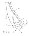
- Figure 1 illustrates in section a bead portion of a heavy load tire, for example, a tire for a bus or truck.
- the outer surface 20 and inner surface 22 of the tire are indicated to provide reference orientation.
- the bead portion includes a bead core 24, which in the illustrated embodiment is formed as a rectangularly profiled coil of steel wires. As known in the art, other profiles may be used for the bead core, including oval and circular.
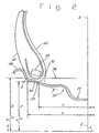
- the bead portion mounts on a rim 50. Tension in the bead core 24 is transmitted to the rim by compression of the rubber between the bead core 24 and the rim seat 52 to secure the bead, and hence the tire, to the rim.
- the bead portion is shaped to have a seat face 26, a flattened region that engages the seat 52 of the rim 50.
- a reference seat point 28 near an outer end of the seat face 26 corresponds to a standardized reference point S on the rim.
- the Tire & Rim Association in its Yearbook publishes standard dimensions for rims, in which the reference point S locates a point on the rim at a nominal rim diameter and rim width.
- the two points 28 and S substantially coincide.
- the seat point 28 is not actually located on the tire bead; however, this point is easily identified by those skilled in the art, and is commonly used in specifying the mounted diameter and width of a tire.
- the section of rim 50 shown in Figure 2 indicates the radius R and half width X rather than the diameter and width.
- the rim seat 52 is formed as a frustoconical section with respect to the axis of rotation A-A of the rim.
- the seat 52 forms a seat angle 56 of 15° with respect to the axis of rotation A-A.
- a 15° seat angle is used for rims for heavy load vehicles such as trucks and buses.
- the tire bead seat 26 ends at a tip 30 that represents a transition point where the end surface 32 of the bead curves away from the bead seat 26 to the inner surface 22 of the tire sidewall.
- the end surface 32 has a rounded shape in making the transition from the bead seat 26 to the inner surface 22 of the tire.
- Figure 3 shows a conventional bead 80 is illustrated mounted on a rim 50.
- the bead seat 82 of the conventional bead 80 is relatively longer and ends in a triangular shaped tip 84. Beads having this triangular tip, or bead toe, are common in the industry because it is believed that the elongated bead seat 82 ensures that a proper air-tight seal is formed.
- the longer bead seat 82 under the bead core 86 is believed to help stabilize the bead on the rim and help resist forces encountered when the vehicle is moving and turning and the wheels are rolling.
- the rim 50 includes a so-called drop center or well 54.
- the rim flange 58 is passed over the rim flange 58 and positioned in the well 54.
- the other side of the tire is then passed over the rim flange 58.
- the tire is then inflated to seat the beads on the rim seats.
- the opposite actions are performed.
- Forcing the beads over the rim flanges require a tool that deforms the tire bead, by twisting, bending and stretching it, to create sufficient clearance.
- the elongated, triangular bead toe 84 is difficult to move over the rim flange 58, even with a tool.
- the action of the tool and the forces imparted on the bead in passing over the flange can damage the bead toe, particularly in older tires, in which the rubber has oxidized and become brittle.
- the less resilient rubber can be cracked or broken.
- a broken bead toe can expose the bead, or result in the loss of integrity of the bead seat, either rendering the tire unfit for service.
- a tire bead could be securely seated and provide an air-tight seal with a rounded bead toe, thus eliminating the problems of the conventional bead toe.
- the short bead toe is easier to move over a rim flange, requiring less deformation, and therefore, is less subject to breaking.
- a bead in accordance with the invention requires less material and is thus, lighter in weight and less expensive to manufacture.
- a tire bead in accordance with the invention has a bead toe that includes a seat surface 26 ending in a transition point 30 and there joining an inner surface 32.
- An included angle 36 defined by the seat surface and a line T with origin at the transition point 30 and tangent to the inner surface 32 is in a range of 105° and 150°, inclusive. The included angle is measured in the direction that includes the bead toe. Preferably, the included angle 36 is in a range of 130° to 150°.
- the bead toe of the invention is also defined by the location of the transition point 30 relative to the seat point 28 or rim seat point S.
- the line Z-Z represents the equatorial plane, that is, the center of the rim and center of a mounted tire along the axis of rotation A-A.
- the nominal radius R of the rim is measured from the axis of rotation A-A.
- the axial distance X of the seat point S is half the nominal width, and is measured from the center line Z-Z of the rim.
- the nominal width and diameter for a rim of a particular size are published by the Tire & Rim Association in the Yearbook.
- the seat point S is defined for each standardized rim and the tires that fit on that rim, that is, the distances R and X can be calculated from standard data, and are useful as references.
- the transition point 30 is located relative to the rim seat point S when the tire is positioned with seat points 28 coinciding with point S as being at a radial distance P in a range of 0.95 R to 0.97 R. It is understood that the tire having two beads, for both seat points 28 to coincide with the reference rim seat points S, the tire would be positioned as if the tire were mounted on a rim. This may be accomplished by actually mounting the tire on an appropriate rim, or using a device that can establish the appropriate bead locations.
- transition point 30 is at an axial distance Y of at least 0.78 X.
- the transition point 30 is axially inward of the center of the bead core 24.
- the transition point 30, of course, cannot be at an axial distance from the tire center greater than that of the seat point S or 28.
- a tire in accordance with the invention can be manufactured using a mold specially adapted to form the bead toe.
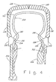
- Figure 4 is a highly simplified, sectional representation of a mold in accordance with the invention.
- the mold includes a membrane 100 that is filled with a heated fluid for transmitting pressure and heat to the interior of the tire.
- the ends 102 of the membrane 100 are clamped in upper 104 and lower 106 membrane plates.
- Upper 110 and lower 112 bead rings, upper 114 and lower 116 sidewall plates, and tread rings 118, 120 are mounted in the mold to form the exterior of the tire.
- a tire being cured in the mold will reside in a space 90 defined between the membrane 100 and the bead rings, sidewall plates and tread rings.
- the bead rings 110, 112 each include a conical ridge 124 defining a seat face 130 to shape the bead seat and a guide surface 132 to guide the membrane 100.
- the membrane 100 extends along the guide surface 132 around a point at the end of the seat face 130 to mold the bead toe of the tire.
- the point at the end of the seat face 130 corresponds to the transition point 30 of the tire bead toe (see Figures 1 and 2).
- the conical ridge 124 ensures that the transition point 30 of the tire bead is appropriately located.
- the guide surface 132 diverts the membrane 100 from a horizontal disposition at the clamped ends to bend toward the equatorial plane of the tire so that the seat face 130 and membrane 100 as it departs from the conical ridge 124 define an included angle in a range of 105° to 155°, and preferably, in a range of 130° to 150°. Accordingly, an included angle between the seat face 130 and the guide surface 132 is in a range of approximately 30° to 95°. Fluid pressure inside the membrane causes the membrane to curve around the tire bead and conform with the inner surface of the tire.
- a mold in accordance with the invention provides a better cure of the bead toe by eliminating empty space in the mold.
- the rubber does not have to first flow into the space, and accordingly, molding pressure on and heat transfer to the bead is equalized early in the molding process.
Description
- The invention relates to a tire for heavy load carrying vehicles, for example, trucks and buses. More particularly, the invention relates to a heavy load tire having a bead toe shaped for improved durability to survive dismounting and remounting during the service life of the tire. The invention also relates to a mold for forming the tire.
- The tire bead is the portion of the tire that engages the rim. The bead typically includes a flattened surface defining a section of a cone that mates with the seat of the rim to transfer the forces of the bead core or cable to secure the tire to the rim. The bead seat surface also forms an airtight seal to retain pressurized air in the tire. In conventional truck and bus tires, the bead terminates in a triangular-shaped bead toe extending from the bead coil or bead core toward the axis of rotation of the tire.
- Truck and bus tires using a 15° drop center rim typically have an elongated bead toe, which is believed to help secure the bead to the rim seat and help resist forces during use that would dismount the bead. In addition, the elongated bead toe is believed to help ensure the integrity of the airtight seal. An elongated bead toe, however, can interfere with mounting and dismounting the tire on a rim, which actions involve forcing the bead toe over the outer flange of the rim.
- Truck and bus tires are designed and manufactured with heavy duty carcasses capable of a useful life far exceeding the life of the tread. Vehicle operators commonly retread such tires to obtain the optimum value from the carcass. A long haul truck tire, for example, may be retreaded three or four times, which requires a similar number of dismounting and remounting steps.
- In addition, a tire may be dismounted during its life to perform repairs to the carcass from road hazard damage.
- A problem with mounting and dismounting a tire is that forcing the bead over the rim flange puts a great deal of stress on the bead and bead toe. As a tire ages and the rubber becomes brittle from oxidation, the stresses can damage the bead toe. If severe, this damage can shorten or end the useful life of the carcass.
- The invention provides a solution in a novel shape for the bead portion that eliminates a large portion of the bead toe in comparison to conventional tires, without sacrificing the mounting integrity of the tire bead.
- According to the invention, a tire for mounting on a rim having an approximately 15° bead seat, that is, a truck or bus tire, has a bead toe that is truncated and rounded in comparison to a conventional bead toe. The bead toe in accordance with the invention is defined by a seat face and an inner surface of the bead portion defining an included angle in a range of 105° to 150°. More preferably, the included angle is in a range of 130° to 150°.
- According to another aspect of the invention, the seat face of the bead terminates in a transition point that is located, with respect to the equatorial plane of the tire, not less than 0.78 times the axial distance of the seat point from the equatorial plane when the seat point is positioned as when mounted on an appropriate rim.
- According to yet another aspect of the invention, the transition point is located with respect to the center of rotation of the tire a radial distance in a range of 0.95 times the radial distance of the seat point from the center of rotation to 0.97 times the radial distance of the seat point from the center of rotation with the seat point located as when mounted on a rim.
- A mold in accordance with the invention includes bead rings having conical ridges including a bead seat forming face and a membrane guide surface. The conical ridges guide the mold membrane from a radial disposition to bend toward the equatorial plane of the tire. The membrane extending from the conical ridge makes and angle with the bead seat forming face that is in a range of 105° to 155°, and preferably 130° to 150°, to form the rounded bead toe.
- The invention will be better understood with reference to the following description in conjunction with the appended drawings, in which:
- Figure 1 is a section view of a bead of a tire in accordance with the present invention;
- Figure 2 is a section view of the tire bead of Figure 1 mounted on a rim;
- Figure 3 is a section view of a conventional tire bead mounted on a rim; and,
- Figure 4 is a section view of a portion of a mold in accordance with the invention.
- Figure 1 illustrates in section a bead portion of a heavy load tire, for example, a tire for a bus or truck. The
outer surface 20 andinner surface 22 of the tire are indicated to provide reference orientation. The bead portion includes abead core 24, which in the illustrated embodiment is formed as a rectangularly profiled coil of steel wires. As known in the art, other profiles may be used for the bead core, including oval and circular. - Referring now also to Figure 2, the bead portion mounts on a
rim 50. Tension in thebead core 24 is transmitted to the rim by compression of the rubber between thebead core 24 and therim seat 52 to secure the bead, and hence the tire, to the rim. The bead portion is shaped to have aseat face 26, a flattened region that engages theseat 52 of therim 50. Areference seat point 28 near an outer end of theseat face 26 corresponds to a standardized reference point S on the rim. The Tire & Rim Association in its Yearbook publishes standard dimensions for rims, in which the reference point S locates a point on the rim at a nominal rim diameter and rim width. When the tire is properly mounted on a rim, the twopoints 28 and S substantially coincide. As shown in Figure 1, theseat point 28 is not actually located on the tire bead; however, this point is easily identified by those skilled in the art, and is commonly used in specifying the mounted diameter and width of a tire. - The section of
rim 50 shown in Figure 2 indicates the radius R and half width X rather than the diameter and width. Therim seat 52 is formed as a frustoconical section with respect to the axis of rotation A-A of the rim. Theseat 52 forms aseat angle 56 of 15° with respect to the axis of rotation A-A. A 15° seat angle is used for rims for heavy load vehicles such as trucks and buses. - The
tire bead seat 26 ends at atip 30 that represents a transition point where theend surface 32 of the bead curves away from thebead seat 26 to theinner surface 22 of the tire sidewall. As may be seen in Figure 1 and Figure 2, theend surface 32 has a rounded shape in making the transition from thebead seat 26 to theinner surface 22 of the tire. - By comparison, Figure 3 shows a
conventional bead 80 is illustrated mounted on arim 50. Thebead seat 82 of theconventional bead 80 is relatively longer and ends in a triangular shapedtip 84. Beads having this triangular tip, or bead toe, are common in the industry because it is believed that theelongated bead seat 82 ensures that a proper air-tight seal is formed. In addition, the longerbead seat 82 under thebead core 86 is believed to help stabilize the bead on the rim and help resist forces encountered when the vehicle is moving and turning and the wheels are rolling. - A problem with
conventional beads 80 is related to mounting and dismounting the tire. As seen in Figure 3, therim 50 includes a so-called drop center or well 54. During mounting, one side of the tire is passed over therim flange 58 and positioned in thewell 54. The other side of the tire is then passed over therim flange 58. The tire is then inflated to seat the beads on the rim seats. When dismounting the tire, the opposite actions are performed. - Forcing the beads over the rim flanges require a tool that deforms the tire bead, by twisting, bending and stretching it, to create sufficient clearance. The elongated,
triangular bead toe 84 is difficult to move over therim flange 58, even with a tool. In addition, the action of the tool and the forces imparted on the bead in passing over the flange can damage the bead toe, particularly in older tires, in which the rubber has oxidized and become brittle. The less resilient rubber can be cracked or broken. A broken bead toe can expose the bead, or result in the loss of integrity of the bead seat, either rendering the tire unfit for service. - The inventors discovered that a tire bead could be securely seated and provide an air-tight seal with a rounded bead toe, thus eliminating the problems of the conventional bead toe. The short bead toe is easier to move over a rim flange, requiring less deformation, and therefore, is less subject to breaking. In addition, a bead in accordance with the invention requires less material and is thus, lighter in weight and less expensive to manufacture.
- Returning, to Figure 1, a tire bead in accordance with the invention has a bead toe that includes a
seat surface 26 ending in atransition point 30 and there joining aninner surface 32. An includedangle 36 defined by the seat surface and a line T with origin at thetransition point 30 and tangent to theinner surface 32 is in a range of 105° and 150°, inclusive. The included angle is measured in the direction that includes the bead toe. Preferably, the includedangle 36 is in a range of 130° to 150°. - Referring to Figure 2, the bead toe of the invention is also defined by the location of the
transition point 30 relative to theseat point 28 or rim seat point S. The line Z-Z represents the equatorial plane, that is, the center of the rim and center of a mounted tire along the axis of rotation A-A. The nominal radius R of the rim is measured from the axis of rotation A-A. The axial distance X of the seat point S is half the nominal width, and is measured from the center line Z-Z of the rim. The nominal width and diameter for a rim of a particular size are published by the Tire & Rim Association in the Yearbook. - The seat point S is defined for each standardized rim and the tires that fit on that rim, that is, the distances R and X can be calculated from standard data, and are useful as references. According to the invention, the
transition point 30 is located relative to the rim seat point S when the tire is positioned withseat points 28 coinciding with point S as being at a radial distance P in a range of 0.95 R to 0.97 R. It is understood that the tire having two beads, for both seat points 28 to coincide with the reference rim seat points S, the tire would be positioned as if the tire were mounted on a rim. This may be accomplished by actually mounting the tire on an appropriate rim, or using a device that can establish the appropriate bead locations. - In addition, the
transition point 30 is at an axial distance Y of at least 0.78 X. Preferably, thetransition point 30 is axially inward of the center of thebead core 24. Thetransition point 30, of course, cannot be at an axial distance from the tire center greater than that of the seat point S or 28. - A tire in accordance with the invention can be manufactured using a mold specially adapted to form the bead toe. Figure 4 is a highly simplified, sectional representation of a mold in accordance with the invention. The mold includes a
membrane 100 that is filled with a heated fluid for transmitting pressure and heat to the interior of the tire. The ends 102 of themembrane 100 are clamped in upper 104 and lower 106 membrane plates.Upper 110 and lower 112 bead rings, upper 114 and lower 116 sidewall plates, and tread rings 118, 120 are mounted in the mold to form the exterior of the tire. A tire being cured in the mold will reside in aspace 90 defined between themembrane 100 and the bead rings, sidewall plates and tread rings. - The bead rings 110, 112 each include a
conical ridge 124 defining aseat face 130 to shape the bead seat and aguide surface 132 to guide themembrane 100. Themembrane 100 extends along theguide surface 132 around a point at the end of theseat face 130 to mold the bead toe of the tire. The point at the end of theseat face 130 corresponds to thetransition point 30 of the tire bead toe (see Figures 1 and 2). Theconical ridge 124 ensures that thetransition point 30 of the tire bead is appropriately located. Theguide surface 132 diverts themembrane 100 from a horizontal disposition at the clamped ends to bend toward the equatorial plane of the tire so that theseat face 130 andmembrane 100 as it departs from theconical ridge 124 define an included angle in a range of 105° to 155°, and preferably, in a range of 130° to 150°. Accordingly, an included angle between theseat face 130 and theguide surface 132 is in a range of approximately 30° to 95°. Fluid pressure inside the membrane causes the membrane to curve around the tire bead and conform with the inner surface of the tire. - A mold in accordance with the invention provides a better cure of the bead toe by eliminating empty space in the mold. The rubber does not have to first flow into the space, and accordingly, molding pressure on and heat transfer to the bead is equalized early in the molding process.
- The invention has been described in terms of preferred principles, embodiments, and structure. However, those skilled in the art will appreciate that the invention can be practiced without strict adherence to the described embodiments, and that variations and substitutions may be made without departing from the invention as defined in the following claims.
Claims (5)
- In a tire for mounting on a rim having a conical seat of approximately 15°, said tire having two beads, one bead on each side of an equatorial plane, each bead having a substantially frustoconical shaped seat face (26) and an inner surface (32), the seat face and inner surface meeting at a transition point (30), characterized by the seat face and inner surface defining an included angle (36) about the transition point in a range of 105° to 155°.
- In a tire according to claim 1, the included angle between the seat face and inner surface being in a range of 130° to 150°.
- In a tire according to claim 1 or 2, the invention further comprising the transition point (30) being located at a radial distance (P) from a center of rotation of the tire that is 0.95 to 0.97 times a radial distance (R) of the seat point (S) from the center of rotation of the tire.
- In a tire according to one of the claims 1 to 3, the invention further comprising the transition point (30) being located an axial distance (Y) from the equatorial plane that is at least 0.78 times and not greater than an axial distance (X) of the seat point (S) from the equatorial plane.
- A mold for a heavy load tire, comprising:a membrane (100) for mold forming an interior of a tire;upper (104) and lower (106) membrane plates for clamping free ends of the membrane in a position parallel to an equatorial plane of the mold;upper (110) and lower (112) bead rings mounted radially outward of the membrane plates for mold forming bead portions of the tire and for guiding the membrane from the membrane plates to the interior of the tire, each bead ring having a conical ridge (124) defining a seat forming surface (130) and a guide surface (132) meeting at a point, an included angle formed between the seat forming surface and an extension of the guide surface past the point is in a range of 105° to 155°.
Applications Claiming Priority (1)
| Application Number | Priority Date | Filing Date | Title |
|---|---|---|---|
| PCT/US1999/024447 WO2002032697A1 (en) | 1999-10-18 | 1999-10-18 | Tire with rounded bead toe and a mold for forming the tire |
Publications (2)
| Publication Number | Publication Date |
|---|---|
| EP1240033A1 EP1240033A1 (en) | 2002-09-18 |
| EP1240033B1 true EP1240033B1 (en) | 2006-10-04 |
Family
ID=22273858
Family Applications (1)
| Application Number | Title | Priority Date | Filing Date |
|---|---|---|---|
| EP99974269A Expired - Lifetime EP1240033B1 (en) | 1999-10-18 | 1999-10-18 | Tire with rounded bead toe and a mold for forming the tire |
Country Status (10)
| Country | Link |
|---|---|
| EP (1) | EP1240033B1 (en) |
| JP (1) | JP2004511383A (en) |
| KR (1) | KR100701447B1 (en) |
| CN (1) | CN1202967C (en) |
| AU (1) | AU2297802A (en) |
| CA (1) | CA2355770C (en) |
| DE (1) | DE69933482T2 (en) |
| MX (1) | MXPA01006233A (en) |
| RU (1) | RU2232682C2 (en) |
| WO (1) | WO2002032697A1 (en) |
Cited By (3)
| Publication number | Priority date | Publication date | Assignee | Title |
|---|---|---|---|---|
| US9108468B2 (en) | 2011-11-30 | 2015-08-18 | Michelin Recherche Et Technique S.A. | Tire bead mounting verification system |
| DE102016223026A1 (en) | 2016-11-22 | 2018-05-24 | Continental Reifen Deutschland Gmbh | Device for vulcanizing commercial vehicle tires |
| DE102020215727A1 (en) | 2020-12-11 | 2022-06-15 | Continental Reifen Deutschland Gmbh | commercial vehicle tires |
Families Citing this family (6)
| Publication number | Priority date | Publication date | Assignee | Title |
|---|---|---|---|---|
| JP4952925B2 (en) * | 2007-07-18 | 2012-06-13 | 横浜ゴム株式会社 | Pneumatic tire vulcanization molding method and apparatus |
| KR100987415B1 (en) * | 2008-07-11 | 2010-10-12 | 한국건설기술연구원 | Device for testing an algae growth |
| JP5363217B2 (en) * | 2009-07-01 | 2013-12-11 | 住友ゴム工業株式会社 | Mold for retread tire and method for manufacturing retread tire using the same |
| JP6665530B2 (en) | 2015-12-25 | 2020-03-13 | 横浜ゴム株式会社 | Pneumatic tire |
| DE102017222282A1 (en) | 2017-12-08 | 2019-06-13 | Continental Reifen Deutschland Gmbh | Commercial vehicle tires |
| KR102463604B1 (en) | 2021-02-15 | 2022-11-08 | 한국타이어앤테크놀로지 주식회사 | Bead section with multiple profiles applied |
Family Cites Families (6)
| Publication number | Priority date | Publication date | Assignee | Title |
|---|---|---|---|---|
| BE623749A (en) * | 1961-12-08 | |||
| FR2303677A2 (en) * | 1975-03-13 | 1976-10-08 | Uniroyal | PROCESS FOR TREATING A PNEUMATIC BANDAGE WRAP TO AVOID CREEPING OF THE WEAR STRIPS OF THE HEELS |
| US4057091A (en) * | 1976-04-07 | 1977-11-08 | The Firestone Tire & Rubber Company | Pneumatic tire |
| JPH01297310A (en) * | 1988-05-24 | 1989-11-30 | Ohtsu Tire & Rubber Co Ltd :The | Pneumatic tyre |
| JPH0558120A (en) * | 1991-08-29 | 1993-03-09 | Bridgestone Corp | Tubeless pneumatic radial tire for heavy duty service |
| US5464051A (en) * | 1993-11-05 | 1995-11-07 | The Goodyear Tire & Rubber Company | Radial ply tire with specified bead portion design |
-
1999
- 1999-10-18 AU AU22978/02A patent/AU2297802A/en not_active Abandoned
- 1999-10-18 WO PCT/US1999/024447 patent/WO2002032697A1/en active IP Right Grant
- 1999-10-18 JP JP2002535906A patent/JP2004511383A/en active Pending
- 1999-10-18 RU RU2001116562/11A patent/RU2232682C2/en not_active IP Right Cessation
- 1999-10-18 KR KR1020017007395A patent/KR100701447B1/en not_active IP Right Cessation
- 1999-10-18 MX MXPA01006233A patent/MXPA01006233A/en not_active IP Right Cessation
- 1999-10-18 DE DE69933482T patent/DE69933482T2/en not_active Expired - Lifetime
- 1999-10-18 CA CA002355770A patent/CA2355770C/en not_active Expired - Fee Related
- 1999-10-18 EP EP99974269A patent/EP1240033B1/en not_active Expired - Lifetime
- 1999-10-18 CN CNB998146048A patent/CN1202967C/en not_active Expired - Fee Related
Cited By (4)
| Publication number | Priority date | Publication date | Assignee | Title |
|---|---|---|---|---|
| US9108468B2 (en) | 2011-11-30 | 2015-08-18 | Michelin Recherche Et Technique S.A. | Tire bead mounting verification system |
| DE102016223026A1 (en) | 2016-11-22 | 2018-05-24 | Continental Reifen Deutschland Gmbh | Device for vulcanizing commercial vehicle tires |
| DE102020215727A1 (en) | 2020-12-11 | 2022-06-15 | Continental Reifen Deutschland Gmbh | commercial vehicle tires |
| WO2022122092A1 (en) | 2020-12-11 | 2022-06-16 | Continental Reifen Deutschland Gmbh | Commercial vehicle tyre |
Also Published As
| Publication number | Publication date |
|---|---|
| DE69933482T2 (en) | 2007-03-29 |
| CN1384788A (en) | 2002-12-11 |
| AU2297802A (en) | 2002-04-29 |
| RU2232682C2 (en) | 2004-07-20 |
| DE69933482D1 (en) | 2006-11-16 |
| CN1202967C (en) | 2005-05-25 |
| CA2355770C (en) | 2009-01-13 |
| CA2355770A1 (en) | 2001-04-18 |
| EP1240033A1 (en) | 2002-09-18 |
| MXPA01006233A (en) | 2002-06-21 |
| KR100701447B1 (en) | 2007-03-30 |
| WO2002032697A1 (en) | 2002-04-25 |
| KR20020039263A (en) | 2002-05-25 |
| JP2004511383A (en) | 2004-04-15 |
Similar Documents
| Publication | Publication Date | Title |
|---|---|---|
| EP1240033B1 (en) | Tire with rounded bead toe and a mold for forming the tire | |
| US6357502B1 (en) | Tire wheel and its components | |
| JPH0761761B2 (en) | Tube radial tires | |
| US6631747B2 (en) | Assembly for mounting a tire on a hub | |
| EP0922592B1 (en) | Tyre wheel and its components | |
| US5318088A (en) | Rim with inclined seats and assembly of such a rim with a tire | |
| US4274465A (en) | Pneumatic tire and wheel rim assembly | |
| EP0352140A2 (en) | Pneumatic radial tire with high durable bead portions | |
| US20010042582A1 (en) | Tire with rounded bead toe and a mold for forming the tire | |
| JP4180373B2 (en) | Assembly formed of tire and sealing piece and method of manufacturing the same | |
| JPS5975801A (en) | Wheel with pneumatic tire particularly for bicycle | |
| US4732198A (en) | Vehicle wheel | |
| US2868258A (en) | Tubeless tire and rim therefor | |
| AU5197201A (en) | Tire with rounded bead toe and a mould for forming the tire | |
| US20200198411A1 (en) | Tire with no ply turnup | |
| JP2002528332A (en) | Tire and rim assembly | |
| US8109309B2 (en) | Tire with seats of unequal diameters and reverse axial offset in an inflated state | |
| US3674080A (en) | Wheel for high-speed cornering | |
| EP0715975A2 (en) | High-speed heavy duty pneumatic radial tires | |
| EP0317318A2 (en) | Method of manufacturing pneumatic tire | |
| GB2245530A (en) | Pneumatic tyre and wheel assembly | |
| US20210061025A1 (en) | Tire with no bead turnup | |
| US20240042807A1 (en) | Commercial vehicle tyre | |
| JP4252380B2 (en) | Tire mold design method, tire mold and tire manufacturing method | |
| GB2064446A (en) | Tyre and wheel rim assemblies |
Legal Events
| Date | Code | Title | Description |
|---|---|---|---|
| PUAI | Public reference made under article 153(3) epc to a published international application that has entered the european phase |
Free format text: ORIGINAL CODE: 0009012 |
|
| AK | Designated contracting states |
Kind code of ref document: A1 Designated state(s): AT BE CH CY DE DK ES FI FR GB GR IE IT LI LU MC NL PT SE |
|
| AX | Request for extension of the european patent |
Free format text: AL;LT;LV;MK;RO;SI |
|
| 17P | Request for examination filed |
Effective date: 20021025 |
|
| RBV | Designated contracting states (corrected) |
Designated state(s): DE ES FR GB IT |
|
| GRAP | Despatch of communication of intention to grant a patent |
Free format text: ORIGINAL CODE: EPIDOSNIGR1 |
|
| GRAS | Grant fee paid |
Free format text: ORIGINAL CODE: EPIDOSNIGR3 |
|
| GRAA | (expected) grant |
Free format text: ORIGINAL CODE: 0009210 |
|
| AK | Designated contracting states |
Kind code of ref document: B1 Designated state(s): DE ES FR GB IT |
|
| PG25 | Lapsed in a contracting state [announced via postgrant information from national office to epo] |
Ref country code: IT Free format text: LAPSE BECAUSE OF FAILURE TO SUBMIT A TRANSLATION OF THE DESCRIPTION OR TO PAY THE FEE WITHIN THE PRESCRIBED TIME-LIMIT;WARNING: LAPSES OF ITALIAN PATENTS WITH EFFECTIVE DATE BEFORE 2007 MAY HAVE OCCURRED AT ANY TIME BEFORE 2007. THE CORRECT EFFECTIVE DATE MAY BE DIFFERENT FROM THE ONE RECORDED. Effective date: 20061004 |
|
| REG | Reference to a national code |
Ref country code: GB Ref legal event code: FG4D |
|
| REF | Corresponds to: |
Ref document number: 69933482 Country of ref document: DE Date of ref document: 20061116 Kind code of ref document: P |
|
| PG25 | Lapsed in a contracting state [announced via postgrant information from national office to epo] |
Ref country code: ES Free format text: LAPSE BECAUSE OF FAILURE TO SUBMIT A TRANSLATION OF THE DESCRIPTION OR TO PAY THE FEE WITHIN THE PRESCRIBED TIME-LIMIT Effective date: 20070115 |
|
| ET | Fr: translation filed | ||
| PLBE | No opposition filed within time limit |
Free format text: ORIGINAL CODE: 0009261 |
|
| STAA | Information on the status of an ep patent application or granted ep patent |
Free format text: STATUS: NO OPPOSITION FILED WITHIN TIME LIMIT |
|
| 26N | No opposition filed |
Effective date: 20070705 |
|
| PGFP | Annual fee paid to national office [announced via postgrant information from national office to epo] |
Ref country code: GB Payment date: 20101013 Year of fee payment: 12 Ref country code: IT Payment date: 20101023 Year of fee payment: 12 |
|
| GBPC | Gb: european patent ceased through non-payment of renewal fee |
Effective date: 20121018 |
|
| PG25 | Lapsed in a contracting state [announced via postgrant information from national office to epo] |
Ref country code: GB Free format text: LAPSE BECAUSE OF NON-PAYMENT OF DUE FEES Effective date: 20121018 |
|
| PG25 | Lapsed in a contracting state [announced via postgrant information from national office to epo] |
Ref country code: IT Free format text: LAPSE BECAUSE OF NON-PAYMENT OF DUE FEES Effective date: 20121018 |
|
| REG | Reference to a national code |
Ref country code: FR Ref legal event code: PLFP Year of fee payment: 17 |
|
| PGFP | Annual fee paid to national office [announced via postgrant information from national office to epo] |
Ref country code: DE Payment date: 20151022 Year of fee payment: 17 |
|
| PGFP | Annual fee paid to national office [announced via postgrant information from national office to epo] |
Ref country code: FR Payment date: 20151023 Year of fee payment: 17 |
|
| REG | Reference to a national code |
Ref country code: DE Ref legal event code: R119 Ref document number: 69933482 Country of ref document: DE |
|
| REG | Reference to a national code |
Ref country code: FR Ref legal event code: ST Effective date: 20170630 |
|
| PG25 | Lapsed in a contracting state [announced via postgrant information from national office to epo] |
Ref country code: FR Free format text: LAPSE BECAUSE OF NON-PAYMENT OF DUE FEES Effective date: 20161102 Ref country code: DE Free format text: LAPSE BECAUSE OF NON-PAYMENT OF DUE FEES Effective date: 20170503 |