EP1240032B1 - High and medium performance tyre for vehicles - Google Patents
High and medium performance tyre for vehicles Download PDFInfo
- Publication number
- EP1240032B1 EP1240032B1 EP00987316A EP00987316A EP1240032B1 EP 1240032 B1 EP1240032 B1 EP 1240032B1 EP 00987316 A EP00987316 A EP 00987316A EP 00987316 A EP00987316 A EP 00987316A EP 1240032 B1 EP1240032 B1 EP 1240032B1
- Authority
- EP
- European Patent Office
- Prior art keywords
- grooves
- sequence
- tyre according
- pairs
- tyre
- Prior art date
- Legal status (The legal status is an assumption and is not a legal conclusion. Google has not performed a legal analysis and makes no representation as to the accuracy of the status listed.)
- Expired - Lifetime
Links
Images


Classifications
-
- B—PERFORMING OPERATIONS; TRANSPORTING
- B60—VEHICLES IN GENERAL
- B60C—VEHICLE TYRES; TYRE INFLATION; TYRE CHANGING; CONNECTING VALVES TO INFLATABLE ELASTIC BODIES IN GENERAL; DEVICES OR ARRANGEMENTS RELATED TO TYRES
- B60C11/00—Tyre tread bands; Tread patterns; Anti-skid inserts
- B60C11/03—Tread patterns
- B60C11/032—Patterns comprising isolated recesses
-
- B—PERFORMING OPERATIONS; TRANSPORTING
- B60—VEHICLES IN GENERAL
- B60C—VEHICLE TYRES; TYRE INFLATION; TYRE CHANGING; CONNECTING VALVES TO INFLATABLE ELASTIC BODIES IN GENERAL; DEVICES OR ARRANGEMENTS RELATED TO TYRES
- B60C11/00—Tyre tread bands; Tread patterns; Anti-skid inserts
- B60C11/03—Tread patterns
- B60C11/0302—Tread patterns directional pattern, i.e. with main rolling direction
-
- B—PERFORMING OPERATIONS; TRANSPORTING
- B60—VEHICLES IN GENERAL
- B60C—VEHICLE TYRES; TYRE INFLATION; TYRE CHANGING; CONNECTING VALVES TO INFLATABLE ELASTIC BODIES IN GENERAL; DEVICES OR ARRANGEMENTS RELATED TO TYRES
- B60C11/00—Tyre tread bands; Tread patterns; Anti-skid inserts
- B60C11/03—Tread patterns
- B60C11/0306—Patterns comprising block rows or discontinuous ribs
-
- B—PERFORMING OPERATIONS; TRANSPORTING
- B60—VEHICLES IN GENERAL
- B60C—VEHICLE TYRES; TYRE INFLATION; TYRE CHANGING; CONNECTING VALVES TO INFLATABLE ELASTIC BODIES IN GENERAL; DEVICES OR ARRANGEMENTS RELATED TO TYRES
- B60C11/00—Tyre tread bands; Tread patterns; Anti-skid inserts
- B60C11/03—Tread patterns
- B60C11/0327—Tread patterns characterised by special properties of the tread pattern
- B60C11/033—Tread patterns characterised by special properties of the tread pattern by the void or net-to-gross ratios of the patterns
-
- B—PERFORMING OPERATIONS; TRANSPORTING
- B60—VEHICLES IN GENERAL
- B60C—VEHICLE TYRES; TYRE INFLATION; TYRE CHANGING; CONNECTING VALVES TO INFLATABLE ELASTIC BODIES IN GENERAL; DEVICES OR ARRANGEMENTS RELATED TO TYRES
- B60C11/00—Tyre tread bands; Tread patterns; Anti-skid inserts
- B60C11/03—Tread patterns
- B60C2011/0337—Tread patterns characterised by particular design features of the pattern
- B60C2011/0339—Grooves
- B60C2011/0374—Slant grooves, i.e. having an angle of about 5 to 35 degrees to the equatorial plane
-
- B—PERFORMING OPERATIONS; TRANSPORTING
- B60—VEHICLES IN GENERAL
- B60C—VEHICLE TYRES; TYRE INFLATION; TYRE CHANGING; CONNECTING VALVES TO INFLATABLE ELASTIC BODIES IN GENERAL; DEVICES OR ARRANGEMENTS RELATED TO TYRES
- B60C11/00—Tyre tread bands; Tread patterns; Anti-skid inserts
- B60C11/03—Tread patterns
- B60C2011/0337—Tread patterns characterised by particular design features of the pattern
- B60C2011/0386—Continuous ribs
- B60C2011/0388—Continuous ribs provided at the equatorial plane
-
- Y—GENERAL TAGGING OF NEW TECHNOLOGICAL DEVELOPMENTS; GENERAL TAGGING OF CROSS-SECTIONAL TECHNOLOGIES SPANNING OVER SEVERAL SECTIONS OF THE IPC; TECHNICAL SUBJECTS COVERED BY FORMER USPC CROSS-REFERENCE ART COLLECTIONS [XRACs] AND DIGESTS
- Y10—TECHNICAL SUBJECTS COVERED BY FORMER USPC
- Y10S—TECHNICAL SUBJECTS COVERED BY FORMER USPC CROSS-REFERENCE ART COLLECTIONS [XRACs] AND DIGESTS
- Y10S152/00—Resilient tires and wheels
- Y10S152/903—Non-directional tread pattern having non-circumferential transverse groove following smooth curved path
Definitions
- the invention relates to a high and medium performance tyre for vehicles and, more particularly, to a tyre having characteristics that are especially though not exclusively suitable for use on winding circuits and dry roads.
- a tyre in its more general form comprises: a casing structure including a central crown portion and two axially opposite sides terminating in a pair of ribs for the attachment to the rim of a wheel; a belt structure coaxially associated with the casing structure and a tread band extended coaxially around the belt structure.
- the tread band comprises a raised pattern formed by a plurality of transversal and longitudinal grooves giving rise overall to a plurality of ribs distributed according to configurations of differing types, for example along a central zone straddling the equatorial plane and in at least two shoulder zones extending in positions coaxially opposite the central zone.
- the ribs on the tread strip are subjected to a set of thermo-mechanical stresses, which are all the greater the more severe the conditions of use and which result in changes to their geometry and, over varying time periods, to a deterioration in the tyre's performance.
- JP 53 100503 corresponding with the preamble of claim 1, relates to a tire for motor bicycle, having on its surface subsidiary grooves extending with inclination angle of 0° - 40° to the line perpendicular to the rotational direction of tire, wherein two back angles of said subsidiary grooves are made different from each other to make wear of tire uniform all over the surface.
- the patent application WO 98/25776 refers to a tyre comprising a tread band provided with transversal grooves in three distinct zones, a central zone straddling the equatorial plane and two shoulder zones, so as to define a directional type tread profile, i.e. one having a preferential direction of rotation.
- Each transversal groove comprises a first stretch extending within a shoulder zone according to a direction perpendicular to the equatorial plane and a second stretch extending obliquely inside the equatorial zone.
- transversal grooves are distributed circumferentially with a pitch "p" and extend alternatively from opposite shoulder zones.
- the transversal grooves are distributed in groups; and more specifically, the tread band comprises a first group of three grooves, parallel to one another, repeated circumferentially with a pitch "P" on the left of the equatorial plane and alternating with a second group of three grooves, parallel to one another, and repeated with an identical pitch "P" on the right of the equatorial plane.
- each group the grooves are of decreasing length in the direction of motion of the tyre, such that one of the grooves passes through the equatorial plane whereas the remaining two grooves are terminated in the vicinity of the equatorial plane, at a different distance from the latter.
- the configuration of the transversal grooves is such as to produce, in the space between the alternating groups, a central rib extending circumferentially in continuously zigzag fashion and a plurality of
- transversal blocks that leave from the central rib and stretch obliquely right and left of the equatorial plane in the direction opposite that of rolling of the tyre.
- the state of the art has not fully solved the problem of producing a tyre provided with a tread pattern that may regardlessly be of the symmetrical, asymmetrical or directional type and at the same time be capable of minimizing and rendering even the wear of the tread band while the tyre is rolling, and of improving and rendering uniform the longitudinal and transversal rigidity so as to ensure an effective stability both on the straight and in bends on dry roads, all of which without impairing the characteristics of low rolling resistance, of sufficiently quiet operation and of good driveability including on terrains that are not dry, for example on roads that are wet or covered in snow.
- the tyre described in patent WO 98/25776 has transversal grooves extending with continuity and great density from the shoulder zones to the zone straddling the equatorial plane, thereby giving rise to a plurality of narrow and elongated blocks, arranged obliquely to the equatorial plane and excessively deformable. In this way, uneven wear may occur of the elastomeric material delimiting these grooves, particularly under conditions where the tyre is rolling on a straight, dry road or at any rate under conditions where the stresses acting along the equatorial plane are considerably greater than those acting in a direction perpendicular to this plane.
- a preferred solution consists in providing each intermediate zone, at a predetermined distance from the equatorial zone, with a plurality of transversal grooves, arranged in groups axially opposite each other and at a reciprocal predetermined distance, in such a way that in the space between said grooves a circumferential, continuous rib is defined having a typically zigzag configuration.
- the solution found may be optimized by giving to the central zone of the tread band particular geometric characteristics not present in the other zones (intermediate and/or shoulder) and/or at any rate a pattern different from that of the intermediate and/or shoulder zones in such a way as to obtain an effect of synergy suitable to improve or supplement the performances offered by the patterns of those zones.
- the Applicant has found particular advantage in the differentiating of the density of the transversal grooves possessed by the shoulder zones and by the intermediate zones adjacent thereto, in such a way as to distribute the grooves of the intermediate zones according to a module repeated circumferentially with a pitch different from that with which said grooves are distributed in the shoulder zones.
- the invention relates to a tyre for vehicles according to claim 1.
- Each intermediate zone advantageously comprises a continuous, zigzagging rib and a plurality of continuous, i.e. full, portions of elastomeric material which leave transversally from both sides of each zigzagging rib.
- the reciprocal configuration of the two sequences of transversal grooves means that it is possible to move from one end of each intermediate zone to the other (i.e. from the a-a plane to the b-b plane, or vice versa) without intersecting any groove. Accordingly ample transversal zones are obtained in said intermediate zones that confer undeformability characteristics on the tread band that are particularly favourable for resisting the stresses acting in a bend when the tyre is rolling.
- each pair of grooves has one groove that is longer than the other. Therefore, for the sake of simplicity in the remainder of this description, where reference is made to the abovementioned preferred embodiment, the transversal grooves of each pair shall be indicated as long groove and short groove. In addition, the two ends of each transversal groove shall be indicated respectively as the terminal end and the starting end, both when referring to a groove in position inside the intermediate zone and when considering an opposite groove.
- terminal ends of the long grooves of a pair of grooves belonging to a given sequence are aligned with the terminal ends of the short grooves of a consecutive pair of grooves belonging to the other sequence, and vice versa.
- the pairs of grooves belonging to a given sequence comprise blind grooves.
- blind groove means a groove surrounded by continuous walls without any way in and/or out of the groove in question.
- the grooves of said sequence of pairs are of like shape and, still more preferably, said shape is elliptical.
- transversal grooves of the intermediate zones and the adjacent ones possessed by the shoulder zones may or may not be staggered with respect to each other.
- pairs of transversal grooves of the sequence nearest to the shoulder zone, adjacent to the intermediate zone to which said pairs belong are joined consecutively to the transversal grooves possessed by said shoulder zone.
- the shoulder transversal grooves are arranged perpendicularly to the equatorial plane of the tyre.
- the succession of a pair of transversal grooves respectively of the first and of the second sequence gives rise in the intermediate zone to a module that is repeated circumferentially with a pitch twice the pitch of the transversal grooves found in the shoulder zone.
- the difference between said pitches creates a discontinuity of the edges of the tread along the footprint area which, to its greater advantage, improves noiselessness of the tyre.
- the central zone of the tread band straddling the equatorial plane comprises two circumferential grooves delimiting therein a central rib.
- said central zone comprises a single circumferential groove, preferably of the rectilinear type.
- said one or more central grooves promote the draining of water during rolling of the tyre on wet roads avoiding the formation of a film of water between tyre and road.
- the invention in a second aspect, relates to a premoulded tread band for the re-moulding of worn tyres according to claim 26.
- the transversal grooves of said intermediate zones have an elliptical configuration; still more preferably, the greater axes of said ellipses together form a predetermined angle ⁇ of between 80° and 100°.
- the greater axes of the ellipses corresponding to the transversal grooves of the pairs of grooves of said first sequence form an angle ⁇ of between 35° and 55° with respect to a plane parallel to the equatorial plane Y-Y.
- the grooves of each pair are of different lengths and each of the terminal ends of the grooves of a pair of said sequence is aligned with a like number of terminal ends of the grooves of an axially opposite pair of the other sequence. More particularly, the terminal ends of the longer grooves of the first sequence are aligned with the terminal ends of the shorter grooves axially opposite, that is to say belonging to the second sequence and, by the same token, the terminal ends of the shorter grooves of the first sequence are aligned with the terminal ends of the longer grooves belonging to the second sequence.
- the tread band is characterized in that all the transversal grooves with starting ends near the central zone are blind.
- the tread band according to the invention has a ratio between the width of the central zone and the width (W) of the tread band that is between 0.10 and 0.20 and a ratio between the width of an intermediate zone (L 0 ) and the width of the same tread band of between 0.17 and 0.30.
- the two intermediate zones are of equal width.
- each intermediate zone of the tread band has a full/empty ratio that is between 0.75 and 0.90.
- a high performance tyre for vehicles is generically indicated with the numeral 1, in particular a tyre intended to be fitted on the front axle of a motor vehicle.
- the tyre 1 comprises a casing structure 2, including a central crown portion 3 and two sides 4, 5, said casing structure being provided with a reinforcing ply 2a the opposite ends of which 2b, 2c are wound around corresponding rings 6, 7.
- An elastomeric filler 8 occupying the space defined between the reinforcing ply 2a and the corresponding ends 2b, 2c of the reinforcing ply 2a, is applied to the radially external perimeter edge of the rings 6, 7, arranged in correspondence with the radially internal ends of said sides 4, 5.
- the opposite zones of the tyre 1, each comprising a ring 6, 7 and the filler 8, form the so-called ribs, globally indicated with the numerals 9 and 10, adapted for the attachment of the tyre 1 to a corresponding mounting rim 11 of the wheel of a vehicle.
- a belt structure 12 Coaxially associated with the abovementioned casing structure 2 is a belt structure 12 comprising one or more reinforcing strips 13, made from textile or metallic cords coated in a given compound.
- the tread band 14 is subdivided into a plurality of zones, more precisely:
- the central zone E comprises a central rib 15 with width between 12 and 20 mm and two longitudinal grooves 16 disposed respectively on either side of said rib 15.
- the rib 15 confers on the tyre 1 a suitable longitudinal stability during rolling and the two longitudinal grooves 16 promote the expulsion of water under conditions of travelling on wet roads.
- the central zone E straddles the equatorial plane Y-Y for a stretch equal to at least 10% of the axial width W of the tread band 14, measured between the planes c-c disposed in correspondence with the lateral edges of said tread band.
- the tread band 14 comprises a plurality of transversal grooves, preferably of elongated elliptical shape, according to a configuration comprising two sequences of pairs of grooves repeated circumferentially.
- each intermediate zone F comprises a first sequence of pairs of grooves 17 and a second sequence of pairs of grooves 18 consecutively arranged along the circumferential direction, said second sequence being axially opposite said first sequence along all of the circumferential development.
- each pair of said sequences is made from two distinct grooves, a long one and a short one, at least partly parallel.
- the grooves of said second pairs 18 are of the blind type.
- each pair 17, 18 the longitudinal axis of the short groove has a length that is between 30% and 70% of the length of the long groove. Furthermore the distance "1" between the long groove and the short groove of each pair is between 15 mm and 40 mm, said distance being measured perpendicularly to the longitudinal axis of each groove.
- ⁇ is of 90°.
- all the transversal grooves of the pairs 17 of the first sequence start from the axial planes b-b of separation from the shoulder zones G and terminate with ends 19, 20 at a distance "d" from the longitudinal axis of the respective long grooves of the pairs 18 of the second sequence.
- all the transversal grooves of the pairs 18 of the second sequence start from ends of the intermediate zone F axially opposite the pairs 17 of the first sequence and terminate with ends 21, 22 at distance "d" from the longitudinal axis of the respective long grooves of the pairs 17 of the first sequence.
- the distance "d” is between 5 mm and 25 mm.
- the starting ends of the grooves of the pairs 18 are aligned on one and the same plane, the distance "D" of which from the equatorial plane Y-Y is between 14 mm and 32 mm.
- all the transversal grooves of said pairs 17, 18 have a width of between 3.5 mm and 10 mm and a maximum depth of between 5 mm and 10 mm.
- the tread band 14 comprises further transversal grooves in the shoulder zones G, each of said grooves comprising at least one rectilinear stretch 24 which, with respect to the equatorial plane Y-Y, forms an angle not less than 85° and preferably of 90°.
- each shoulder transversal groove is formed from two stretches 23 and 24, the first (23) approximately 8 mm wide and between 5 mm and 10 mm deep and the second (24) approximately 4 mm wide and between 1 mm and 6 mm deep. Moreover the ratio between the lengths of said two stretches 23, 24 is between 30% and 50%.
- the stretches 23 of the shoulder grooves are joined by a curving stretch to the abovementioned transversal stretches of the pairs 17 of the first sequence belonging to the intermediate zone F.
- this joining stretch is an arc of a circle with radius between 30 mm and 60 mm.
- the pattern of the tread band 14 in the shoulder zones G is discerned mainly from a plurality of transversal grooves 23, 24 repeated circumferentially with a pitch "p".
- the abovementioned joining sections, which join the grooves of the shoulder zones G and the transversal grooves of the pairs 17 of the intermediate zones F, are repeated circumferentially with a like pitch "p".
- the pattern of the intermediate zones F is discerned from pairs of transversal grooves 17, 18 which alternate along the circumferential direction giving rise to a module which is repeated along the circumferential development of the tread band, with a pitch "P" different from the pitch "p" of the shoulder transversal grooves.
- the pitch "P” has a value substantially twice that of the pitch "p".
- a tread band having a single pitch "p” has been described but it will be obvious that the above also applies for tread bands with a pitch "p" circumferentially variable according to a predetermined law, for example with alternations of pitches "p" of two different lengths, respectively a long pitch and a short pitch.
- pitches "p" of between 25 mm and 50 mm when the circumferential development of the tyre, measured along the equatorial plane at the outermost point of the tread band, is between 1750 mm and 2200 mm.
- each shoulder zone G the tread band 14 of the tyre 1 comprises a longitudinal notch 25, also called “disconnection notch” and a longitudinal incision 26.
- the notch 25 and the incision 26 are extended circumferentially in a direction substantially perpendicular to the shoulder transversal grooves 23, 24.
- the longitudinal notch 25 has a depth of about 2 mm and a width of about 3 mm, whereas the longitudinal incision 26 has a width of about 1.5 mm and a depth of between 3 mm and 7 mm.
- Said incisions and notches advantageously improve handling on the wet.
- each shoulder zone G the tyre 1 also comprises a plurality of transversal notches 27 placed between two consecutive shoulder transversal grooves 23,24.
- These notches 27 have a depth of approximately 4 mm and a width of approximately 3 mm and extend axially along a section between the longitudinal notch 25 and the longitudinal incision 26.
- a further embodiment of the invention is illustrated in figure 3 concerning a particular tyre 28 of the directional type, that is to say provided with an overall pattern having a predetermined direction of rolling (indicated with the arrow R in figure 3) and two intermediate F and shoulder G zones of the tread band, located at the sides of the equatorial plane Y-Y, which are repeated specularly on either side of said equatorial plane.
- the two halves of the tread band 28 comprise the same pattern characteristics as described previously, therefore the elements of the tyre 28 structurally or functionally the same as those already illustrated with reference to the tyre 1 shown in figures 1 and 2 will be indicated using the same reference numerals and will not be described any further.
- the intermediate F and shoulder G zones of the tread band 28, as well as being specular with respect to the equatorial plane Y-Y, are also staggered in the circumferential direction by an amount equal to approximately 50% of the pitch "p" of the shoulder transversal grooves.
- each shoulder zone G having been defined with L and the width of the tread band measured between the planes c-c with W
- the preferred embodiments of the tyre according to this invention envisage a ratio L/W of preferably between 0.10 and 0.28.
- a first advantage consists, for example, in the fact that by having defined a system of transversal grooves which never intersect in the two intermediate zones .F, the tread band is endowed with a considerable ability of reaction in relation to the external stress forces.
- the intermediate zones F of the tread band 1 comprise a particular pattern the geometrical characteristics of which depend, among other things, on the distance "1" between the two grooves of a same pair (17, 18), on the particular conformation of the space between the two grooves of a same pair, on the distance "d” between the two pairs of transversal grooves 17, 18 distributed in a pitch "P”, and on the orientation of all the pairs among themselves and in relation to the equatorial plane Y-Y.
- These characteristics result in the formation, in each intermediate zone F, of a rib extending in zigzag fashion for the entire circumferential development and a plurality of continuous portions of elastomeric material which depart obliquely from both sides of said zigzagging rib.
- the two zigzag ribs 29 and the oblique portions 30, 31 are formed from continuous parts of elastomeric material allowing them to oppose the stresses exerted by the ground on the tyre during rolling.
- the resulting stresses have a direction on the tyre depending both on the resistance characteristics of the compound used in the tread band and on the prevalence of one of the two forces directed in the running direction or in the transversal direction.
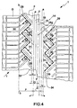
- the plurality of oblique portions 30, 31 disposed as illustrated in figure 4 constitute "struts" suitable for discharging the quoted resultant stresses along their axis.
- these ribs with their resistance will also contribute to elastically balancing the stresses acting on the tyre.
- the active struts will be those relative to the plurality of portions 30 also oriented in the direction of said resulting inside the two intermediate zones.
- the tyre according to the invention is favourably suitable for use on winding circuits.
- the uniform rigidity of the two intermediate zones F contributes greatly to minimizing the phenomena of tread band wear and to rendering said phenomena even so as to avoid uneven wear of said band.
- a further advantage of the tyre according to the invention consists of the fact that, thanks to the alternating distribution of the pairs of transversal grooves of the first and second sequence belonging to said intermediate zones and the great density of the transversal grooves in the shoulder zones, the number of transversal grooves present in the footprint area during the rolling of the tyre is maintained advantageously constant.
- This aspect signifies the optimization of the distribution of the pressures in the footprint area during rolling of the tyre.
- a further advantage of this invention consists of the fact that the pattern of the tread band has a high of full/empty ratio.
- the high full/empty ratio is determined not only by the presence of the continuous zigzagging ribs of elastomeric material 29 and of the oblique portions 30, 31 which depart obliquely therefrom, but also by the presence of longitudinal ribs 33, 34 included between the starting ends of the grooves of the pairs 18 of the second sequence of the intermediate zones F and the planes a-a of separation of the intermediate zones F from the central zone E.
- the width "T" of the ribs 33, 34 is between 3 mm and 21 mm.
- the presence of the continuous ribs 33, 34 ensures that the portion of intermediate zone F closest to the central zone E has a greater rigidity than that possessed by the remainder of the intermediate zone F adjacent to the shoulder zone G.
- the high full/empty ratio with values between 0.65 and 0.85 entails low values of the specific pressures in the footprint area and low deformability of the tread band in this area with resultant advantageous attenuation of the noise of the tyre of the invention.
- the tyre according to the invention having transversal grooves in the intermediate zones F mutually isolated and separated from the equatorial plane Y-Y through the central zone E has lesser deformability than tyres not provided with transversal grooves running from the shoulder zones up to near the equatorial plane, and sometimes beyond. Therefore, thanks to a tread band of greater mass than the known tyres, this tyre is advantageously endowed not only with less noise, but also with less resistance to rolling.
- said tyre comprises a tread band provided in the intermediate zones with a plurality of blind transversal grooves capable of capturing and retaining the snow, substituting the rubber-snow friction with a snow-snow friction, the latter as is known being much greater than the former.
Abstract
Description
- The invention relates to a high and medium performance tyre for vehicles and, more particularly, to a tyre having characteristics that are especially though not exclusively suitable for use on winding circuits and dry roads.
- A tyre in its more general form comprises: a casing structure including a central crown portion and two axially opposite sides terminating in a pair of ribs for the attachment to the rim of a wheel; a belt structure coaxially associated with the casing structure and a tread band extended coaxially around the belt structure.
- Generally the tread band comprises a raised pattern formed by a plurality of transversal and longitudinal grooves giving rise overall to a plurality of ribs distributed according to configurations of differing types, for example along a central zone straddling the equatorial plane and in at least two shoulder zones extending in positions coaxially opposite the central zone.
- As the tyre rolls, the ribs on the tread strip are subjected to a set of thermo-mechanical stresses, which are all the greater the more severe the conditions of use and which result in changes to their geometry and, over varying time periods, to a deterioration in the tyre's performance.
- In particular, the contact with the ground during running produces a flexing of the trailing edge of the ribs of the tyre, said edge by drooping radially towards the inside and moving in the direction opposite the direction of running produces a restriction of the groove that separates it from the next rib. This phenomenon leaves the leading edge of the latter-named open to a tangential stress which is repeated cyclically at each revolution of the wheel, causing a typical uneven and premature wear known as "saw-tooth wear".
-
JP 53 100503 claim 1, relates to a tire for motor bicycle, having on its surface subsidiary grooves extending with inclination angle of 0° - 40° to the line perpendicular to the rotational direction of tire, wherein two back angles of said subsidiary grooves are made different from each other to make wear of tire uniform all over the surface. - Tyres that try to minimize the number of ribs and strengthen their structure are known in the sector art.,
- For example, the patent application
WO 98/25776 - Each transversal groove comprises a first stretch extending within a shoulder zone according to a direction perpendicular to the equatorial plane and a second stretch extending obliquely inside the equatorial zone.
- The transversal grooves are distributed circumferentially with a pitch "p" and extend alternatively from opposite shoulder zones.
- More particularly, in the abovementioned tread band the transversal grooves are distributed in groups; and more specifically, the tread band comprises a first group of three grooves, parallel to one another, repeated circumferentially with a pitch "P" on the left of the equatorial plane and alternating with a second group of three grooves, parallel to one another, and repeated with an identical pitch "P" on the right of the equatorial plane.
- In each group the grooves are of decreasing length in the direction of motion of the tyre, such that one of the grooves passes through the equatorial plane whereas the remaining two grooves are terminated in the vicinity of the equatorial plane, at a different distance from the latter.
- The configuration of the transversal grooves is such as to produce, in the space between the alternating groups, a central rib extending circumferentially in continuously zigzag fashion and a plurality of
- transversal blocks that leave from the central rib and stretch obliquely right and left of the equatorial plane in the direction opposite that of rolling of the tyre.
- The state of the art has not fully solved the problem of producing a tyre provided with a tread pattern that may regardlessly be of the symmetrical, asymmetrical or directional type and at the same time be capable of minimizing and rendering even the wear of the tread band while the tyre is rolling, and of improving and rendering uniform the longitudinal and transversal rigidity so as to ensure an effective stability both on the straight and in bends on dry roads, all of which without impairing the characteristics of low rolling resistance, of sufficiently quiet operation and of good driveability including on terrains that are not dry, for example on roads that are wet or covered in snow.
- The tyre described in patent
WO 98/25776 - The Applicant has observed that a better solution to the problem outlined above could be achieved by having recourse to a tread band substantially free of blocks and divided into at least five zones: a central zone straddling the equatorial plane, two intermediate zones disposed to the sides of the central zone and two shoulder zones, arranged in a position axially external to said two intermediate zones.
- The Applicant has found that a preferred solution consists in providing each intermediate zone, at a predetermined distance from the equatorial zone, with a plurality of transversal grooves, arranged in groups axially opposite each other and at a reciprocal predetermined distance, in such a way that in the space between said grooves a circumferential, continuous rib is defined having a typically zigzag configuration.
- The Applicant has further noted that the solution found may be optimized by giving to the central zone of the tread band particular geometric characteristics not present in the other zones (intermediate and/or shoulder) and/or at any rate a pattern different from that of the intermediate and/or shoulder zones in such a way as to obtain an effect of synergy suitable to improve or supplement the performances offered by the patterns of those zones.
- In addition, the Applicant has found particular advantage in the differentiating of the density of the transversal grooves possessed by the shoulder zones and by the intermediate zones adjacent thereto, in such a way as to distribute the grooves of the intermediate zones according to a module repeated circumferentially with a pitch different from that with which said grooves are distributed in the shoulder zones.
- In a first aspect, the invention relates to a tyre for vehicles according to
claim 1. - Each intermediate zone advantageously comprises a continuous, zigzagging rib and a plurality of continuous, i.e. full, portions of elastomeric material which leave transversally from both sides of each zigzagging rib. These characteristics in each intermediate zone produce a structure that is resistant in both the longitudinal and transversal direction, capable of reacting elastically to the stresses acting on the tread band during rolling of the tyre.
- It must be pointed out in particular that the reciprocal configuration of the two sequences of transversal grooves means that it is possible to move from one end of each intermediate zone to the other (i.e. from the a-a plane to the b-b plane, or vice versa) without intersecting any groove. Accordingly ample transversal zones are obtained in said intermediate zones that confer undeformability characteristics on the tread band that are particularly favourable for resisting the stresses acting in a bend when the tyre is rolling.
- In a preferred embodiment of the invention, each pair of grooves has one groove that is longer than the other. Therefore, for the sake of simplicity in the remainder of this description, where reference is made to the abovementioned preferred embodiment, the transversal grooves of each pair shall be indicated as long groove and short groove. In addition, the two ends of each transversal groove shall be indicated respectively as the terminal end and the starting end, both when referring to a groove in position inside the intermediate zone and when considering an opposite groove.
- Preferably the terminal ends of the long grooves of a pair of grooves belonging to a given sequence are aligned with the terminal ends of the short grooves of a consecutive pair of grooves belonging to the other sequence, and vice versa.
- Still more preferably, the pairs of grooves belonging to a given sequence comprise blind grooves.
- Here and in the remainder of the description, and in the accompanying claims as well, the term "blind groove" means a groove surrounded by continuous walls without any way in and/or out of the groove in question.
- Preferably the grooves of said sequence of pairs are of like shape and, still more preferably, said shape is elliptical.
- The transversal grooves of the intermediate zones and the adjacent ones possessed by the shoulder zones may or may not be staggered with respect to each other.
- In a preferred embodiment the pairs of transversal grooves of the sequence nearest to the shoulder zone, adjacent to the intermediate zone to which said pairs belong, are joined consecutively to the transversal grooves possessed by said shoulder zone.
- According to a particularly preferred embodiment, in view of its being able to confer advantageous qualities of tractability on the tyre of the invention, the shoulder transversal grooves are arranged perpendicularly to the equatorial plane of the tyre.
- Still more preferably, the succession of a pair of transversal grooves respectively of the first and of the second sequence gives rise in the intermediate zone to a module that is repeated circumferentially with a pitch twice the pitch of the transversal grooves found in the shoulder zone.
- Advantageously the difference between said pitches (namely between the pitch of the shoulder zones and the pitch of the intermediate zones) creates a discontinuity of the edges of the tread along the footprint area which, to its greater advantage, improves noiselessness of the tyre.
- Preferably, the central zone of the tread band straddling the equatorial plane comprises two circumferential grooves delimiting therein a central rib. Alternatively said central zone comprises a single circumferential groove, preferably of the rectilinear type.
- Advantageously said one or more central grooves promote the draining of water during rolling of the tyre on wet roads avoiding the formation of a film of water between tyre and road.
- In a second aspect, the invention relates to a premoulded tread band for the re-moulding of worn tyres according to
claim 26. - Preferably the transversal grooves of said intermediate zones have an elliptical configuration; still more preferably, the greater axes of said ellipses together form a predetermined angle α of between 80° and 100°.
- In a preferred embodiment, the greater axes of the ellipses corresponding to the transversal grooves of the pairs of grooves of said first sequence form an angle γ of between 35° and 55° with respect to a plane parallel to the equatorial plane Y-Y.
- Preferably the grooves of each pair are of different lengths and each of the terminal ends of the grooves of a pair of said sequence is aligned with a like number of terminal ends of the grooves of an axially opposite pair of the other sequence. More particularly, the terminal ends of the longer grooves of the first sequence are aligned with the terminal ends of the shorter grooves axially opposite, that is to say belonging to the second sequence and, by the same token, the terminal ends of the shorter grooves of the first sequence are aligned with the terminal ends of the longer grooves belonging to the second sequence.
- Conveniently the tread band is characterized in that all the transversal grooves with starting ends near the central zone are blind.
- Preferably the tread band according to the invention has a ratio between the width of the central zone and the width (W) of the tread band that is between 0.10 and 0.20 and a ratio between the width of an intermediate zone (L0) and the width of the same tread band of between 0.17 and 0.30.
- Preferably the two intermediate zones are of equal width.
- In another preferred embodiment of the invention, each intermediate zone of the tread band has a full/empty ratio that is between 0.75 and 0.90.
- Further characteristics and advantages will become apparent from the description that follows of a preferred embodiment of a tyre according to this invention, provided purely by way of an illustrative, non-restrictive example, and with reference to the accompanying drawings, where:
- Figure 1 is a transverse sectional view of a tyre according to the invention, in particular of a tyre intended to be fitted on the front wheel of a vehicle;
- Figure 2 is a partial development in plan view of the tread band of the tyre of figure 1;
- Figure 3 is a partial development in plan view of a tread band according to a further embodiment of the tyre of the invention;
- Figure 4 illustrates some details of the partial plan view of figure 2.
- With reference to figures 1 and 2, a high performance tyre for vehicles is generically indicated with the
numeral 1, in particular a tyre intended to be fitted on the front axle of a motor vehicle. - The
tyre 1 comprises a casing structure 2, including a central crown portion 3 and two sides 4, 5, said casing structure being provided with a reinforcingply 2a the opposite ends of which 2b, 2c are wound around corresponding rings 6, 7. - An elastomeric filler 8, occupying the space defined between the reinforcing
ply 2a and thecorresponding ends 2b, 2c of the reinforcingply 2a, is applied to the radially external perimeter edge of the rings 6, 7, arranged in correspondence with the radially internal ends of said sides 4, 5. - As is known, the opposite zones of the
tyre 1, each comprising a ring 6, 7 and the filler 8, form the so-called ribs, globally indicated with thenumerals tyre 1 to a corresponding mounting rim 11 of the wheel of a vehicle. - Coaxially associated with the abovementioned casing structure 2 is a
belt structure 12 comprising one or more reinforcingstrips 13, made from textile or metallic cords coated in a given compound. - A
tread band 14, into the thickness of which a pattern illustrated in greater detail in figure 2 has been impressed, is applied in a known way on thebelt structure 12. - Hereinbelow, for simplicity of the description, only that part of the
tread band 14 of figure 2 disposed on the left of the equatorial plane Y-Y shall be detailed, as the side located on the right of said plane is identical after being turned over by 180° and being subsequently staggered by a predetermined amount in the circumferential direction. - The
tread band 14 is subdivided into a plurality of zones, more precisely: - a central zone E straddling the equatorial plane Y-Y and included between two central planes a-a, substantially parallel to the equatorial plane Y-Y,
- two intermediate zones F, each of which extending between one side of the zone E, namely between a plane a-a, and an intermediate plane b-b substantially parallel to said equatorial plane Y-Y,
- two shoulder zones G each of which delimited between one side of the intermediate zone F, namely between a plane b-b, and an axially external plane c-c substantially parallel to said equatorial plane Y-Y and located in correspondence with the side edge of said tread band.
- In the embodiment illustrated, the central zone E comprises a
central rib 15 with width between 12 and 20 mm and twolongitudinal grooves 16 disposed respectively on either side of saidrib 15. - To advantage, the
rib 15 confers on the tyre 1 a suitable longitudinal stability during rolling and the twolongitudinal grooves 16 promote the expulsion of water under conditions of travelling on wet roads. - The central zone E straddles the equatorial plane Y-Y for a stretch equal to at least 10% of the axial width W of the
tread band 14, measured between the planes c-c disposed in correspondence with the lateral edges of said tread band. - It must be pointed out that the quoted conformation of the central zone E must not be understood in any restrictive sense for the invention, it in fact constituting one example of the various embodiments.
- In the intermediate zones F, the
tread band 14 comprises a plurality of transversal grooves, preferably of elongated elliptical shape, according to a configuration comprising two sequences of pairs of grooves repeated circumferentially. - In greater detail, each intermediate zone F comprises a first sequence of pairs of grooves 17 and a second sequence of pairs of
grooves 18 consecutively arranged along the circumferential direction, said second sequence being axially opposite said first sequence along all of the circumferential development. - In the embodiment shown in figure 2, each pair of said sequences is made from two distinct grooves, a long one and a short one, at least partly parallel. In addition, the grooves of said second pairs 18 are of the blind type.
- Conveniently, as illustrated in figure 2, in each
pair 17, 18 the longitudinal axis of the short groove has a length that is between 30% and 70% of the length of the long groove. Furthermore the distance "1" between the long groove and the short groove of each pair is between 15 mm and 40 mm, said distance being measured perpendicularly to the longitudinal axis of each groove. - The grooves of the pair 17, in relation to the direction of the equatorial plane Y-Y, form an angle γ of between 35° and 55°. In addition the longitudinal axes of the grooves of the pairs 17 of the first sequence, together with the longitudinal axis of the groove of the
pair 18 closest to the groove of said pairs 17, form a predetermined angle α of between 80° and 100°. Preferably α is of 90°. - More specifically, all the transversal grooves of the pairs 17 of the first sequence start from the axial planes b-b of separation from the shoulder zones G and terminate with
ends 19, 20 at a distance "d" from the longitudinal axis of the respective long grooves of thepairs 18 of the second sequence. - In turn, all the transversal grooves of the
pairs 18 of the second sequence start from ends of the intermediate zone F axially opposite the pairs 17 of the first sequence and terminate withends 21, 22 at distance "d" from the longitudinal axis of the respective long grooves of the pairs 17 of the first sequence. Conveniently the distance "d" is between 5 mm and 25 mm. - The starting ends of the grooves of the
pairs 18 are aligned on one and the same plane, the distance "D" of which from the equatorial plane Y-Y is between 14 mm and 32 mm. - In the example illustrated in figure 2 all the terminal ends 19, 20, 21, 22 of the grooves of the first 17 and second 18 pairs are aligned on two distinct planes substantially parallel to the equatorial plane Y-Y, and more precisely:
- all the ends 19 of the long grooves of the pairs 17 and all the
ends 22 of the short grooves of thesecond pairs 18 are aligned on one and the same plane, the distance D1 of which from the equatorial plane Y-Y is between 22 mm and 82 mm; - all the
ends 20 of the short grooves of the first pairs 17 and all the ends 21 of the long grooves of thepairs 18 are aligned on one and the same plane, the distance D2 of which from the equatorial plane Y-Y is between 30 mm and 95 mm; - Conveniently all the transversal grooves of said pairs 17, 18 have a width of between 3.5 mm and 10 mm and a maximum depth of between 5 mm and 10 mm.
- The
tread band 14 comprises further transversal grooves in the shoulder zones G, each of said grooves comprising at least onerectilinear stretch 24 which, with respect to the equatorial plane Y-Y, forms an angle not less than 85° and preferably of 90°. - More in detail, each shoulder transversal groove is formed from two
stretches stretches - It was found to advantage that the reduced width of the
shoulder groove 23, 24 (in moving from thestretch 24 to stretch 23 in the axial direction when approaching the equatorial plane Y-Y), entailing an increase in the "full" area in the shoulder zone, contributes to improving the roadholding in bends of the tyre according to the invention. - In the embodiment illustrated in figure 2, the
stretches 23 of the shoulder grooves are joined by a curving stretch to the abovementioned transversal stretches of the pairs 17 of the first sequence belonging to the intermediate zone F. Preferably this joining stretch is an arc of a circle with radius between 30 mm and 60 mm. - As shown in figure 2, the pattern of the
tread band 14 in the shoulder zones G is discerned mainly from a plurality oftransversal grooves - The pattern of the intermediate zones F, as stated, is discerned from pairs of
transversal grooves 17, 18 which alternate along the circumferential direction giving rise to a module which is repeated along the circumferential development of the tread band, with a pitch "P" different from the pitch "p" of the shoulder transversal grooves. In the preferred embodiment illustrated in figure 2 the pitch "P" has a value substantially twice that of the pitch "p". For the sake of simplicity, a tread band having a single pitch "p" has been described but it will be obvious that the above also applies for tread bands with a pitch "p" circumferentially variable according to a predetermined law, for example with alternations of pitches "p" of two different lengths, respectively a long pitch and a short pitch. - The preferred embodiments of this invention envisage pitches "p" of between 25 mm and 50 mm when the circumferential development of the tyre, measured along the equatorial plane at the outermost point of the tread band, is between 1750 mm and 2200 mm.
- Conveniently in each shoulder zone G the
tread band 14 of thetyre 1 comprises alongitudinal notch 25, also called "disconnection notch" and alongitudinal incision 26. - The
notch 25 and theincision 26 are extended circumferentially in a direction substantially perpendicular to the shouldertransversal grooves - The
longitudinal notch 25 has a depth of about 2 mm and a width of about 3 mm, whereas thelongitudinal incision 26 has a width of about 1.5 mm and a depth of between 3 mm and 7 mm. - Said incisions and notches advantageously improve handling on the wet.
- Conveniently in each shoulder zone G the
tyre 1 also comprises a plurality oftransversal notches 27 placed between two consecutive shouldertransversal grooves - These
notches 27 have a depth of approximately 4 mm and a width of approximately 3 mm and extend axially along a section between thelongitudinal notch 25 and thelongitudinal incision 26. - The use of these notches contributes advantageously to reducing noise of the tyre.
- A further embodiment of the invention is illustrated in figure 3 concerning a
particular tyre 28 of the directional type, that is to say provided with an overall pattern having a predetermined direction of rolling (indicated with the arrow R in figure 3) and two intermediate F and shoulder G zones of the tread band, located at the sides of the equatorial plane Y-Y, which are repeated specularly on either side of said equatorial plane. The two halves of thetread band 28 comprise the same pattern characteristics as described previously, therefore the elements of thetyre 28 structurally or functionally the same as those already illustrated with reference to thetyre 1 shown in figures 1 and 2 will be indicated using the same reference numerals and will not be described any further. - As may be seen in the embodiment illustrated in figure 3, the intermediate F and shoulder G zones of the
tread band 28, as well as being specular with respect to the equatorial plane Y-Y, are also staggered in the circumferential direction by an amount equal to approximately 50% of the pitch "p" of the shoulder transversal grooves. - The width of each shoulder zone G having been defined with L and the width of the tread band measured between the planes c-c with W, the preferred embodiments of the tyre according to this invention envisage a ratio L/W of preferably between 0.10 and 0.28.
- These preferential values for said ratio, as indeed also the ranges cited above for the dimensional quantities described, are valid for tyres having measurements 185/60R14 or 225/50R16 or 255/45R18.
- With this invention a plurality of advantages may be attained.
- A first advantage consists, for example, in the fact that by having defined a system of transversal grooves which never intersect in the two intermediate zones .F, the tread band is endowed with a considerable ability of reaction in relation to the external stress forces.
- In order to better clarify this aspect, reference is now made to a
tread band 14 of thetyre 1 illustrated in figure 4, perfectly equal to figure 2 except for a few additional references included by way of explanation of the above. - The intermediate zones F of the
tread band 1 comprise a particular pattern the geometrical characteristics of which depend, among other things, on the distance "1" between the two grooves of a same pair (17, 18), on the particular conformation of the space between the two grooves of a same pair, on the distance "d" between the two pairs oftransversal grooves 17, 18 distributed in a pitch "P", and on the orientation of all the pairs among themselves and in relation to the equatorial plane Y-Y. These characteristics result in the formation, in each intermediate zone F, of a rib extending in zigzag fashion for the entire circumferential development and a plurality of continuous portions of elastomeric material which depart obliquely from both sides of said zigzagging rib. - This configuration is represented schematically in figure 4 wherein, for greater clarity, both the circumferential
zigzag rib 29 and theoblique portions 30, 31 departing therefrom are depicted in dashed lines. - The two
zigzag ribs 29 and theoblique portions 30, 31 are formed from continuous parts of elastomeric material allowing them to oppose the stresses exerted by the ground on the tyre during rolling. - Having said all this, it is known that under conditions of rolling in a bend a tyre is subject to stresses resulting from the vectorial composition of a force acting in the direction of running and a force perpendicular to the equatorial plane needed to equilibrate the centrifugal force.
- The resulting stresses have a direction on the tyre depending both on the resistance characteristics of the compound used in the tread band and on the prevalence of one of the two forces directed in the running direction or in the transversal direction.
- In accordance with the invention the plurality of
oblique portions 30, 31 disposed as illustrated in figure 4 constitute "struts" suitable for discharging the quoted resultant stresses along their axis. Besides, as the oblique portions are connected to the zigzaggingribs 29, these ribs with their resistance will also contribute to elastically balancing the stresses acting on the tyre. - In particular, in the case where the resultant of the stresses is directed in the direction of the arrow "f" in figure 4, the active struts will be those relative to the plurality of
portions 30 also oriented in the direction of said resulting inside the two intermediate zones. F. - As a result of this ability to elastically resist the transversal forces, the tyre according to the invention is favourably suitable for use on winding circuits.
- In addition, as can be seen from figure 4, from each stretch of the dashed line constituting the circumferential
zigzag rib 29 firstly anoblique portion 30 and then an oblique portion 31 alternately depart in a direction substantially perpendicular to theportion 30, so that the two portions, substantially of equal dimensions, confer a substantial uniform rigidity both in the transverse and in the longitudinal direction on each intermediate zone F. - Advantageously the uniform rigidity of the two intermediate zones F, together with the absence of isolated blocks, contributes greatly to minimizing the phenomena of tread band wear and to rendering said phenomena even so as to avoid uneven wear of said band.
- A further advantage of the tyre according to the invention consists of the fact that, thanks to the alternating distribution of the pairs of transversal grooves of the first and second sequence belonging to said intermediate zones and the great density of the transversal grooves in the shoulder zones, the number of transversal grooves present in the footprint area during the rolling of the tyre is maintained advantageously constant. This aspect signifies the optimization of the distribution of the pressures in the footprint area during rolling of the tyre.
- A further advantage of this invention consists of the fact that the pattern of the tread band has a high of full/empty ratio.
- In fact, as may be seen in figure 4, the high full/empty ratio is determined not only by the presence of the continuous zigzagging ribs of
elastomeric material 29 and of theoblique portions 30, 31 which depart obliquely therefrom, but also by the presence oflongitudinal ribs pairs 18 of the second sequence of the intermediate zones F and the planes a-a of separation of the intermediate zones F from the central zone E. - Preferably the width "T" of the
ribs - The presence of the
continuous ribs - Furthermore, the high full/empty ratio with values between 0.65 and 0.85 entails low values of the specific pressures in the footprint area and low deformability of the tread band in this area with resultant advantageous attenuation of the noise of the tyre of the invention.
- In particular, the tyre according to the invention, having transversal grooves in the intermediate zones F mutually isolated and separated from the equatorial plane Y-Y through the central zone E has lesser deformability than tyres not provided with transversal grooves running from the shoulder zones up to near the equatorial plane, and sometimes beyond. Therefore, thanks to a tread band of greater mass than the known tyres, this tyre is advantageously endowed not only with less noise, but also with less resistance to rolling.
- Yet another advantage of this invention consists of the excellent driving performances obtainable also on roads covered in snow. In fact, according to one cf the preferred embodiments according to the invention described in the foregoing, said tyre comprises a tread band provided in the intermediate zones with a plurality of blind transversal grooves capable of capturing and retaining the snow, substituting the rubber-snow friction with a snow-snow friction, the latter as is known being much greater than the former.
- Those acquainted with the sector art, having understood the invention as described above, will now also be able to effect all those choices, variants and modifications of the variables associated with this invention needed to solve the specific technical problem that they have tackled, namely to give precedence to a specific behavioural aspect (for example, the performance in miles with respect to noise, by increasing the depth of the inclined grooves, or the tractability with respect to wear, by increasing the depth and/or width of the transversal grooves, etc.) in relation to the severity of operation in the particular application of the vehicle that it is intended to equip with the tyres of the invention.
Claims (26)
- Tyre for wheels of vehicles comprising:- a casing structure (2) including a central crown portion (3) and two axially opposite sides (4,5) terminating in a pair of ribs for the attachment of said tyre to a corresponding rim of a wheel;- a belt structure (12) coaxially associated with said casing structure (2);- a tread band (14), extended coaxially around said belt structure (12), moulded with a relief pattern comprising:characterized in that each pair (17,18) comprising two distinct grooves at least partly parallel, the grooves of each pair (17) of said first sequence being inclined at a predetermined angle (α) to the grooves of each pair (18) of said second sequence, said internal ends of a pair (17,18) of a given sequence being at a predetermined distance (d) from the groove of the pair (17,18) of the other sequence nearest to said ends, said predetermined distance (d) giving rise circumferentially to a continuous, zigzagging rib from which continuous oblique portions, each delimited by the grooves of one of said pairs (17,18), depart alternatively from opposite ends.a central zone (E), straddling the equatorial plane (Y-Y) of said tyre and extending between two central planes (a-a) substantially parallel to said equatorial plane;two intermediate zones (F), each of which extending between one side of said central zone (E) and an intermediate plane (b-b) substantially parallel to said equatorial plane (Y-Y);two shoulder zones (G), each of which extending between the axially outermost side of one of said intermediate zones (F) and an axially external plane (c-c), substantially parallel to said equatorial plane (Y-Y) and located in correspondence with the side edge of said tread band, said intermediate (F) and shoulder (G) zones comprising a plurality of transversal grooves (23,24),each intermediate zone (F) comprises two sequences of pairs (17,18) of transversal grooves, first and second sequence respectively, the pairs (17) of said first sequence being consecutively alternated over the entire circumferential length of the tyre with the pairs (18) of said second sequence, said grooves of said first sequence departing from axially opposite ends of said intermediate zones (F) and terminating with ends inside the latter,
- Tyre according to claim 1, characterized in that the transversal grooves of said intermediate zone (F) are delimited lengthwise by substantially rectilinear walls and are parallel to each other.
- Tyre according to claim 1, characterized in that said predetermined angle α is between 80° and 100°.
- Tyre according to claim 3, characterized in that the grooves of the pairs (17) of said first sequence form, with respect to a plane parallel to the equatorial plane (Y-Y), an angle γ of between 35° and 55°.
- Tyre according to claim 1, characterized in that each of said pairs (17, 18) comprises one groove longer than the other.
- Tyre according to claim 5, characterized in that the short groove of each pair (17,18) has a length that is between 30% and 70% of the long groove.
- Tyre according to claim 1, characterized in that the terminal ends (19,21) of the long grooves of a pair (17,18) are aligned with the terminal ends of the short grooves (20,22) of the other pair (17,18) and vice versa.
- Tyre according to claim 7, characterized in that the terminal ends (19) of the long grooves of the pairs (17) of the first sequence and the terminal ends (22) of the short grooves of the second sequence are aligned on a circumferential plane, the distance (D1) of which from the equatorial plane is respectively between 22 mm and 82 mm.
- Tyre according to claim 7, characterized in that the terminal ends (20) of the short grooves of the pairs (17) of the first sequence and the terminal ends (21) of the long grooves of the pairs (18) of the second sequence are aligned on a circumferential plane, the distance D2 of which from the equatorial plane is between 30 mm and 95 mm.
- Tyre according to claim 1, characterized in that the grooves of the pairs (18) of the second sequence are extended towards the inside of the intermediate zone (F) starting from a plane, the distance (D) of which from the equatorial plane (Y-Y) is between 14 mm and 32 mm.
- Tyre according to claim 1, characterized in that the grooves of the pairs (18) of the second sequence are blind.
- Tyre according to claim 1, characterized in that the predetermined distance between the internal ends of a pair (17,18) and the longitudinal axis of the nearest groove of the axially opposite pair (17,18) is constant along all of the circumferential development.
- Tyre according to claim 1, characterized in that the transversal grooves of the intermediate zone (F) have a depth of between 5 mm and 10 mm.
- Tyre according to claim 1, characterized in that the transversal grooves of the intermediate zone (F) have a width of between 3.5 mm and 10 mm.
- Tyre according to claim 1, characterized in that the grooves of the pairs (17) of the first sequence of the intermediate zone (F) and the transversal grooves of the shoulder zone (G) are rectilinear and joined together by a curving stretch with a radius of curvature of between 30 mm and 60 mm.
- Tyre according to claim 1, characterized in that the transversal grooves of the shoulder zone (G) comprise a stretch perpendicular to the equatorial plane (Y-Y).
- Tyre according to claim 1, characterized in that the pitch of the transversal grooves of the intermediate zone (G) is twice that of the shoulder transversal grooves.
- Tyre according to claim 1, characterized in that the transversal grooves of the shoulder zone (G) have a depth of between 5 mm and 10 mm.
- Tyre according to claim 1, characterized in that the transversal grooves of the shoulder zone (G) have a width of between 3.5 mm and 10 mm.
- Tyre according to claim 1, characterized in that the ratio of the width (L0) of each intermediate zone (F) to the width (W) of the tread band is between 0.17 and 0.30.
- Tyre according to claim 1, characterized in that the ratio of the width of the central zone (E) to the width (W) of the tread band is between 0.10 and 0.20.
- Tyre according to claim 1, characterized in that said central zone (E) comprises two circumferential grooves internally delimiting a central rib.
- Tyre according to claim 1, characterized in that the portion of the tread band (14) on the left of the equatorial plane (Y-Y) when rotated by 180° constitutes the right hand portion.
- Tyre according to claim 1, characterized in that the portion of the tread band (14) on the left of the equatorial plane (Y-Y) is specular to the right-hand portion.
- Tyre according to claim 1, characterized in that the transversal grooves of the pairs (17) of the first sequence start from the axial planes (b-b) of separation from the shoulder zones (G) and terminate with ends (19,20) at a distance "d" from the longitudinal axis of the respective long grooves of the pairs (18) of the second sequence.
- Premoulded tread band for the re-moulding of worn tyres characterized in that it comprises a tread pattern according to any of the previous claims.
Applications Claiming Priority (5)
| Application Number | Priority Date | Filing Date | Title |
|---|---|---|---|
| IT1999MI002516A IT1314249B1 (en) | 1999-12-01 | 1999-12-01 | TIRE FOR VEHICLES AND HIGH AND MEDIUM PERFORMANCE. |
| ITMI992516 | 1999-12-01 | ||
| US18737700P | 2000-03-07 | 2000-03-07 | |
| US187377P | 2000-03-07 | ||
| PCT/EP2000/011897 WO2001039572A1 (en) | 1999-12-01 | 2000-11-29 | High and medium performance tyre for vehicles |
Publications (2)
| Publication Number | Publication Date |
|---|---|
| EP1240032A1 EP1240032A1 (en) | 2002-09-18 |
| EP1240032B1 true EP1240032B1 (en) | 2008-01-09 |
Family
ID=26331695
Family Applications (1)
| Application Number | Title | Priority Date | Filing Date |
|---|---|---|---|
| EP00987316A Expired - Lifetime EP1240032B1 (en) | 1999-12-01 | 2000-11-29 | High and medium performance tyre for vehicles |
Country Status (8)
| Country | Link |
|---|---|
| US (1) | US7131475B2 (en) |
| EP (1) | EP1240032B1 (en) |
| AT (1) | ATE383251T1 (en) |
| AU (1) | AU2360701A (en) |
| DE (1) | DE60037751T2 (en) |
| ES (1) | ES2300283T3 (en) |
| PT (1) | PT1240032E (en) |
| WO (1) | WO2001039572A1 (en) |
Families Citing this family (9)
| Publication number | Priority date | Publication date | Assignee | Title |
|---|---|---|---|---|
| DE602004015165D1 (en) * | 2004-07-16 | 2008-08-28 | Pirelli | HIGH PERFORMANCE TIRES FOR A MOTOR VEHICLE |
| US9873290B2 (en) * | 2004-07-16 | 2018-01-23 | Pirelli Tyre S.P.A. | High-performance tyre for a motor vehicle |
| US7360568B2 (en) * | 2005-01-27 | 2008-04-22 | Bridgestone Firestone North American Tire, Llc | Tire having narrowing sipes |
| US8931532B2 (en) * | 2008-06-30 | 2015-01-13 | Pirelli Tyre, S.P.A. | Rain tyre |
| USD608724S1 (en) | 2009-03-16 | 2010-01-26 | Trek Bicycle Corporation | Bicycle tire tread |
| US8971452B2 (en) | 2012-05-29 | 2015-03-03 | Magnolia Broadband Inc. | Using 3G/4G baseband signals for tuning beamformers in hybrid MIMO RDN systems |
| FR3035822A1 (en) * | 2015-05-07 | 2016-11-11 | Michelin & Cie | ROLLING STRIP COMPRISING A BLOCK PRESENTING A PLURALITY OF CUTTINGS |
| CN106166924B (en) * | 2016-08-26 | 2023-10-27 | 四川远星橡胶有限责任公司 | Tyre for motorcycle |
| JP6521115B1 (en) * | 2018-01-30 | 2019-05-29 | 横浜ゴム株式会社 | Pneumatic tire |
Family Cites Families (12)
| Publication number | Priority date | Publication date | Assignee | Title |
|---|---|---|---|---|
| NL36624C (en) * | 1932-11-04 | |||
| GB488496A (en) * | 1937-01-05 | 1938-07-05 | Firestone Tire & Rubber Co | Improvements in or relating to tyres for vehicle wheels |
| JPS53100503A (en) * | 1977-02-14 | 1978-09-02 | Yokohama Rubber Co Ltd:The | Tire for motor bicycle |
| FR2463687A1 (en) * | 1979-08-20 | 1981-02-27 | Uniroyal Englebert Pneu | TREAD SCULPTURE FOR PNEUMATIC ENVELOPES |
| JPH0399906A (en) * | 1989-09-13 | 1991-04-25 | Yokohama Rubber Co Ltd:The | Pneumatic radial tire |
| JPH0655912A (en) * | 1992-08-07 | 1994-03-01 | Bridgestone Corp | Pneumatic tire |
| JPH07251609A (en) | 1994-03-15 | 1995-10-03 | Bridgestone Corp | Low profile pneumatic tire |
| DE19650655C2 (en) * | 1996-12-06 | 2000-08-24 | Continental Ag | Vehicle tires with cuts in the tread |
| WO1998025776A1 (en) | 1996-12-10 | 1998-06-18 | The Yokohama Rubber Co., Ltd. | Pneumatic tire and pneumatic tire set |
| US6656300B1 (en) * | 1997-09-26 | 2003-12-02 | Pirelli Pneumatici S.P.A. | High performance tire for vehicles |
| EP0904961A1 (en) * | 1997-09-26 | 1999-03-31 | PIRELLI PNEUMATICI S.p.A. | High performance tyre for vehicles |
| US6971425B2 (en) * | 1999-12-01 | 2005-12-06 | Pirelli Pneumatici S.P.A. | Tire for high-performance vehicles and premoulded tread band having an asymmetrical pattern |
-
2000
- 2000-11-29 ES ES00987316T patent/ES2300283T3/en not_active Expired - Lifetime
- 2000-11-29 AU AU23607/01A patent/AU2360701A/en not_active Abandoned
- 2000-11-29 EP EP00987316A patent/EP1240032B1/en not_active Expired - Lifetime
- 2000-11-29 US US10/148,597 patent/US7131475B2/en not_active Expired - Lifetime
- 2000-11-29 DE DE60037751T patent/DE60037751T2/en not_active Expired - Lifetime
- 2000-11-29 AT AT00987316T patent/ATE383251T1/en not_active IP Right Cessation
- 2000-11-29 WO PCT/EP2000/011897 patent/WO2001039572A1/en active IP Right Grant
- 2000-11-29 PT PT00987316T patent/PT1240032E/en unknown
Also Published As
| Publication number | Publication date |
|---|---|
| ES2300283T3 (en) | 2008-06-16 |
| EP1240032A1 (en) | 2002-09-18 |
| ATE383251T1 (en) | 2008-01-15 |
| AU2360701A (en) | 2001-06-12 |
| US20030111149A1 (en) | 2003-06-19 |
| PT1240032E (en) | 2008-04-07 |
| WO2001039572A1 (en) | 2001-06-07 |
| US7131475B2 (en) | 2006-11-07 |
| DE60037751T2 (en) | 2009-01-15 |
| DE60037751D1 (en) | 2008-02-21 |
Similar Documents
| Publication | Publication Date | Title |
|---|---|---|
| EP1363790B1 (en) | Tyre tread for motor vehicles, particularly for snow-covered ground | |
| EP0089306B1 (en) | Tire tread | |
| US5361814A (en) | Asymmetric tire | |
| KR100212334B1 (en) | All season type tire tread | |
| EP0602989A1 (en) | Pneumatic tyre | |
| EP0522416B1 (en) | Radial tyre having a tread provided with sub-circumferential longitudinal grooves | |
| CA2255254A1 (en) | Tread profile of a snow tire | |
| EP1930185B1 (en) | Pneumatic tire with spiral grooving | |
| EP2748017A1 (en) | Winter tyre | |
| EP1240032B1 (en) | High and medium performance tyre for vehicles | |
| EP1147022B1 (en) | Tyre for vehicles wheels | |
| CN108819621B (en) | Pneumatic tire for automobile | |
| EP1237737B1 (en) | Tyre for high-performance vehicles | |
| US5109901A (en) | Pneumatic radial tires having a tread including isolated sipes | |
| CN115916554A (en) | Automobile tyre | |
| EP0175829B1 (en) | Pneumatic tires | |
| CA1221607A (en) | Pneumatic tire | |
| EP0752326B1 (en) | Pneumatic tyre | |
| EP4338984A1 (en) | Tire with variable number of lateral blocks per pitch | |
| WO2023242787A1 (en) | Tyre for vehicle wheels | |
| JPH0419202A (en) | Pneumatic radial tire | |
| RU2776721C2 (en) | Tire for vehicle wheels | |
| US4572261A (en) | Pneumatic tire tread | |
| CN115884884A (en) | Tyre for vehicle wheels | |
| CN116648360A (en) | pneumatic tire |
Legal Events
| Date | Code | Title | Description |
|---|---|---|---|
| PUAI | Public reference made under article 153(3) epc to a published international application that has entered the european phase |
Free format text: ORIGINAL CODE: 0009012 |
|
| 17P | Request for examination filed |
Effective date: 20020624 |
|
| AK | Designated contracting states |
Kind code of ref document: A1 Designated state(s): AT BE CH CY DE DK ES FI FR GB GR IE IT LI LU MC NL PT SE |
|
| AX | Request for extension of the european patent |
Free format text: AL;LT;LV;MK;RO;SI |
|
| RAP1 | Party data changed (applicant data changed or rights of an application transferred) |
Owner name: PIRELLI TYRE S.P.A. |
|
| 17Q | First examination report despatched |
Effective date: 20061212 |
|
| GRAP | Despatch of communication of intention to grant a patent |
Free format text: ORIGINAL CODE: EPIDOSNIGR1 |
|
| RBV | Designated contracting states (corrected) |
Designated state(s): AT BE CH CY DE DK ES FI FR GB GR IE IT LI LU MC NL PT SE TR |
|
| GRAS | Grant fee paid |
Free format text: ORIGINAL CODE: EPIDOSNIGR3 |
|
| GRAA | (expected) grant |
Free format text: ORIGINAL CODE: 0009210 |
|
| AK | Designated contracting states |
Kind code of ref document: B1 Designated state(s): AT BE CH CY DE DK ES FI FR GB GR IE IT LI LU MC NL PT SE TR |
|
| REG | Reference to a national code |
Ref country code: GB Ref legal event code: FG4D |
|
| REG | Reference to a national code |
Ref country code: CH Ref legal event code: EP |
|
| REG | Reference to a national code |
Ref country code: IE Ref legal event code: FG4D |
|
| REF | Corresponds to: |
Ref document number: 60037751 Country of ref document: DE Date of ref document: 20080221 Kind code of ref document: P |
|
| REG | Reference to a national code |
Ref country code: PT Ref legal event code: SC4A Free format text: AVAILABILITY OF NATIONAL TRANSLATION Effective date: 20080327 |
|
| REG | Reference to a national code |
Ref country code: SE Ref legal event code: TRGR |
|
| REG | Reference to a national code |
Ref country code: CH Ref legal event code: NV Representative=s name: FIAMMENGHI-FIAMMENGHI |
|
| REG | Reference to a national code |
Ref country code: ES Ref legal event code: FG2A Ref document number: 2300283 Country of ref document: ES Kind code of ref document: T3 |
|
| PG25 | Lapsed in a contracting state [announced via postgrant information from national office to epo] |
Ref country code: FI Free format text: LAPSE BECAUSE OF FAILURE TO SUBMIT A TRANSLATION OF THE DESCRIPTION OR TO PAY THE FEE WITHIN THE PRESCRIBED TIME-LIMIT Effective date: 20080109 |
|
| ET | Fr: translation filed | ||
| PG25 | Lapsed in a contracting state [announced via postgrant information from national office to epo] |
Ref country code: DK Free format text: LAPSE BECAUSE OF FAILURE TO SUBMIT A TRANSLATION OF THE DESCRIPTION OR TO PAY THE FEE WITHIN THE PRESCRIBED TIME-LIMIT Effective date: 20080109 |
|
| PLBE | No opposition filed within time limit |
Free format text: ORIGINAL CODE: 0009261 |
|
| STAA | Information on the status of an ep patent application or granted ep patent |
Free format text: STATUS: NO OPPOSITION FILED WITHIN TIME LIMIT |
|
| 26N | No opposition filed |
Effective date: 20081010 |
|
| PGFP | Annual fee paid to national office [announced via postgrant information from national office to epo] |
Ref country code: AT Payment date: 20081103 Year of fee payment: 9 Ref country code: ES Payment date: 20081126 Year of fee payment: 9 Ref country code: PT Payment date: 20081031 Year of fee payment: 9 |
|
| PGFP | Annual fee paid to national office [announced via postgrant information from national office to epo] |
Ref country code: SE Payment date: 20081128 Year of fee payment: 9 |
|
| PG25 | Lapsed in a contracting state [announced via postgrant information from national office to epo] |
Ref country code: MC Free format text: LAPSE BECAUSE OF NON-PAYMENT OF DUE FEES Effective date: 20081130 |
|
| REG | Reference to a national code |
Ref country code: CH Ref legal event code: PL |
|
| PG25 | Lapsed in a contracting state [announced via postgrant information from national office to epo] |
Ref country code: CY Free format text: LAPSE BECAUSE OF FAILURE TO SUBMIT A TRANSLATION OF THE DESCRIPTION OR TO PAY THE FEE WITHIN THE PRESCRIBED TIME-LIMIT Effective date: 20080109 |
|
| PG25 | Lapsed in a contracting state [announced via postgrant information from national office to epo] |
Ref country code: LI Free format text: LAPSE BECAUSE OF NON-PAYMENT OF DUE FEES Effective date: 20081130 Ref country code: CH Free format text: LAPSE BECAUSE OF NON-PAYMENT OF DUE FEES Effective date: 20081130 Ref country code: IE Free format text: LAPSE BECAUSE OF NON-PAYMENT OF DUE FEES Effective date: 20081201 |
|
| REG | Reference to a national code |
Ref country code: PT Ref legal event code: MM4A Free format text: LAPSE DUE TO NON-PAYMENT OF FEES Effective date: 20100531 |
|
| EUG | Se: european patent has lapsed | ||
| PG25 | Lapsed in a contracting state [announced via postgrant information from national office to epo] |
Ref country code: PT Free format text: LAPSE BECAUSE OF NON-PAYMENT OF DUE FEES Effective date: 20100531 Ref country code: LU Free format text: LAPSE BECAUSE OF NON-PAYMENT OF DUE FEES Effective date: 20081129 |
|
| PG25 | Lapsed in a contracting state [announced via postgrant information from national office to epo] |
Ref country code: AT Free format text: LAPSE BECAUSE OF NON-PAYMENT OF DUE FEES Effective date: 20091129 |
|
| PG25 | Lapsed in a contracting state [announced via postgrant information from national office to epo] |
Ref country code: GR Free format text: LAPSE BECAUSE OF FAILURE TO SUBMIT A TRANSLATION OF THE DESCRIPTION OR TO PAY THE FEE WITHIN THE PRESCRIBED TIME-LIMIT Effective date: 20080410 |
|
| REG | Reference to a national code |
Ref country code: ES Ref legal event code: FD2A Effective date: 20110323 |
|
| PG25 | Lapsed in a contracting state [announced via postgrant information from national office to epo] |
Ref country code: SE Free format text: LAPSE BECAUSE OF NON-PAYMENT OF DUE FEES Effective date: 20091130 |
|
| PG25 | Lapsed in a contracting state [announced via postgrant information from national office to epo] |
Ref country code: ES Free format text: LAPSE BECAUSE OF NON-PAYMENT OF DUE FEES Effective date: 20110310 |
|
| PG25 | Lapsed in a contracting state [announced via postgrant information from national office to epo] |
Ref country code: ES Free format text: LAPSE BECAUSE OF NON-PAYMENT OF DUE FEES Effective date: 20091130 |
|
| REG | Reference to a national code |
Ref country code: FR Ref legal event code: PLFP Year of fee payment: 16 |
|
| REG | Reference to a national code |
Ref country code: FR Ref legal event code: PLFP Year of fee payment: 17 |
|
| PGFP | Annual fee paid to national office [announced via postgrant information from national office to epo] |
Ref country code: NL Payment date: 20161126 Year of fee payment: 17 |
|
| PGFP | Annual fee paid to national office [announced via postgrant information from national office to epo] |
Ref country code: BE Payment date: 20161128 Year of fee payment: 17 |
|
| PGFP | Annual fee paid to national office [announced via postgrant information from national office to epo] |
Ref country code: TR Payment date: 20161108 Year of fee payment: 17 |
|
| REG | Reference to a national code |
Ref country code: FR Ref legal event code: PLFP Year of fee payment: 18 |
|
| REG | Reference to a national code |
Ref country code: NL Ref legal event code: MM Effective date: 20171201 |
|
| REG | Reference to a national code |
Ref country code: BE Ref legal event code: MM Effective date: 20171130 |
|
| PG25 | Lapsed in a contracting state [announced via postgrant information from national office to epo] |
Ref country code: NL Free format text: LAPSE BECAUSE OF NON-PAYMENT OF DUE FEES Effective date: 20171201 |
|
| PG25 | Lapsed in a contracting state [announced via postgrant information from national office to epo] |
Ref country code: BE Free format text: LAPSE BECAUSE OF NON-PAYMENT OF DUE FEES Effective date: 20171130 |
|
| PGFP | Annual fee paid to national office [announced via postgrant information from national office to epo] |
Ref country code: DE Payment date: 20191127 Year of fee payment: 20 |
|
| PGFP | Annual fee paid to national office [announced via postgrant information from national office to epo] |
Ref country code: IT Payment date: 20191125 Year of fee payment: 20 Ref country code: FR Payment date: 20191125 Year of fee payment: 20 |
|
| PGFP | Annual fee paid to national office [announced via postgrant information from national office to epo] |
Ref country code: GB Payment date: 20191127 Year of fee payment: 20 |
|
| REG | Reference to a national code |
Ref country code: DE Ref legal event code: R071 Ref document number: 60037751 Country of ref document: DE |
|
| REG | Reference to a national code |
Ref country code: GB Ref legal event code: PE20 Expiry date: 20201128 |
|
| PG25 | Lapsed in a contracting state [announced via postgrant information from national office to epo] |
Ref country code: GB Free format text: LAPSE BECAUSE OF EXPIRATION OF PROTECTION Effective date: 20201128 |
|
| PG25 | Lapsed in a contracting state [announced via postgrant information from national office to epo] |
Ref country code: TR Free format text: LAPSE BECAUSE OF NON-PAYMENT OF DUE FEES Effective date: 20171129 |