EP1239649A2 - Electronic device molded cover having a releasable emi shield - Google Patents
Electronic device molded cover having a releasable emi shield Download PDFInfo
- Publication number
- EP1239649A2 EP1239649A2 EP02251337A EP02251337A EP1239649A2 EP 1239649 A2 EP1239649 A2 EP 1239649A2 EP 02251337 A EP02251337 A EP 02251337A EP 02251337 A EP02251337 A EP 02251337A EP 1239649 A2 EP1239649 A2 EP 1239649A2
- Authority
- EP
- European Patent Office
- Prior art keywords
- cover
- electronic device
- interior
- emi
- emi shield
- Prior art date
- Legal status (The legal status is an assumption and is not a legal conclusion. Google has not performed a legal analysis and makes no representation as to the accuracy of the status listed.)
- Withdrawn
Links
Images




Classifications
-
- H—ELECTRICITY
- H05—ELECTRIC TECHNIQUES NOT OTHERWISE PROVIDED FOR
- H05K—PRINTED CIRCUITS; CASINGS OR CONSTRUCTIONAL DETAILS OF ELECTRIC APPARATUS; MANUFACTURE OF ASSEMBLAGES OF ELECTRICAL COMPONENTS
- H05K9/00—Screening of apparatus or components against electric or magnetic fields
- H05K9/0007—Casings
- H05K9/0047—Casings being rigid plastic containers having conductive particles, fibres or mesh embedded therein
-
- H—ELECTRICITY
- H04—ELECTRIC COMMUNICATION TECHNIQUE
- H04M—TELEPHONIC COMMUNICATION
- H04M1/00—Substation equipment, e.g. for use by subscribers
- H04M1/02—Constructional features of telephone sets
- H04M1/0202—Portable telephone sets, e.g. cordless phones, mobile phones or bar type handsets
Definitions
- the present invention relates generally to electromagnetic interference (EMI) shielding in electronic devices and deals more specifically with EMI shielding for portable electronic devices such as cellular or radio telephones, and in particular with a molded cover having a releasable EMI shield for such electronic devices.
- EMI electromagnetic interference
- Portable electronic devices particularly portable handheld communication devices such as cellular or radio telephones and the like require electromagnetic interference (EMI) shielding to prevent any electromagnetic signals generated during operation of the device from escaping and interfering with other electronic devices.
- EMI shielding prevents any externally generated electromagnetic signals from entering the device and interfering with its operation.
- electromagnetic signals often develop as a field or as a transient within the radio frequency band of the electromagnetic spectrum, i.e., from between approximately 10 kilohertz and 10 gigahertz.
- Cellular or radio telephones in particular are required by law to adhere to electromagnetic compatibility (EMC) limits as laid down in Type Approval Specifications for Mobile Phones.
- EMC electromagnetic compatibility
- EMC is defined as the ability of a device to function properly in its intended electromagnetic environment and not to be a source of electromagnetic pollution to that environment.
- shielding having the capability of absorbing and/or reflecting EMI energy may be employed both to confine the EMI energy within a source device and to insulate the device or other target devices from other source devices.
- EMI shielding it is known to use a cover or housing shell made of metal to absorb and shield any EMI radiation energy generated by the electronic device.
- One drawback of such metal covers is the additional weight and cost that is added to the electronic device. Additionally, the demand for increasingly smaller portable electronic handheld devices has caused manufacturers to integrate as many functions as possible, including EMI shielding, to reduce both manufacturing cost and the amount of raw material needed.
- One common method to provide EMI shielding in portable electronic devices is to mold or otherwise fabricate the covers or case of the device from metallized plastic; i.e., plastic having metal or other conductive fibers integrated into the plastic.
- metallized plastic covers may provide adequate EMI shielding, they are less than satisfactory for making an electrical ground connection between the cover and an electrical ground circuit path on the electronic circuit board containing the operational electronic components of the electronic device. Special bonding techniques and additional labor steps are required to ensure electrical connection to the metal in the plastic material forming the cover.
- a further disadvantage of such metallized plastic covers utilized for EMI shielding is that it is very difficult, if not impossible, to separate the metal or other electrically conductive fibers from the plastic material into their respective base materials for recycling.
- the cover be a homogeneous structure containing a single thermoplastic polymer blend free of contaminants such as metal fibers and the like, particularly if the product is to be used as raw material for production of a similar product application. Additionally, environmental legislation directed to the recycling of electronic devices may require reuse of materials as raw material for similar product applications, in which case it will be necessary to separate the materials of the cover into respective contaminant-free base materials.
- an object of the present invention to provide an EMI shielded cover for portable electronic devices, such as cellular or radio telephones, wherein the EMI shield is releasable from the cover to facilitate separation of the EMI shield material from the cover material.
- a cover for an electronic device has an interior chamber formed by intersecting wall surfaces and an electromagnetic interference (EMI) shield conforming substantially to the size and shape of the interior chamber is juxtaposed with the interior wall surfaces.
- EMI electromagnetic interference
- the EMI shield is removable from the interior chamber for separating the cover and the EMI shield into their respective individual parts.
- the EMI shield is an electrically conductive fabric sheet.
- the electrically conductive fabric sheet is releasably fastened to the surface of the interior wall by an adhesive applied to a face of the fabric sheet.
- the adhesive are drops of glue in a spaced relation from one another on a face of the fabric sheet.
- the adhesive is an adhesive spray.
- the adhesive is heat activated.
- the electrically conductive fabric sheet comprises a woven mesh of conductive fibers.
- the conductive fibers comprise a silver coated thread.
- the electrically conductive fabric sheet is pliable and further is stretchable.
- the electrically conductive fabric sheet is of sufficient strength to resist tearing during removal from the cover.
- the cover is molded from a thermoplastic polymer blend.
- the EMI shield is fitted to the interior chamber of the cover subsequent to the molding of the cover.
- the EMI shield is pre-formed to the size and shape of the interior chamber.
- the EMI shield is a coating of a conductive polymer paint applied to the interior wall surface, which surface has modified whereby the adhesion force between the conductive polymer paint coating and the surface of the interior wall is less than the inherent cohesion forces of the conductive polymer paint coating itself to allow peeling of the conductive polymer paint coating from the interior wall surfaces.
- portions of the EMI shield are in electrical and mechanical contact with an electrical ground reference potential surface area on a substrate carrying electronic circuit components of the electronic device when the substrate is assembled with the cover.
- a method for providing an EMI shielded electronic device molded cover comprises the steps of providing an EMI shielding material that is conformable to the shape of the interior of the cover; locating the EMI shielding material in the interior of the cover; and releasably securing the EMI shielding material to the interior of the cover, whereby the EMI shielding material is removable to separate the EMI shielding material from the cover without substantial contamination of each by the other to facilitate recycling of the EMI shielding material and the cover into the respective raw material of each.
- the step of providing an EMI shielding material further comprises providing an electrically conductive fabric sheet having an adhesive applied to a face of the fabric sheet.
- the step of providing an EMI shielding material further comprises the steps of reducing the adhesion properties of the surface of the interior of the cover and providing a coating of a conductive polymer paint on the interior surface of the cover.
- Fig. 1 is a top plan view of a cellular telephone of the type with which the present invention may be used and is generally designated 10 .
- the cellular telephone 10 typically includes a case or housing made of a front or top cover 12 and a rear or back cover 14, which, when assembled, provides a chamber or enclosure in which the electronic circuitry and other components of the electronic device are housed and carried.
- Fig. 2 shows by way of example a somewhat schematic perspective view of the rear cover 14 of the cellular telephone 10 illustrated in Fig. 1.
- the rear cover 14 is shown in simplified form and includes an interior rear wall 16 and rear wall surface 24 and an outer peripheral wall 18 extending therefrom and defining the interior area or volume of the rear cover 14 .
- Within the interior area of the rear cover 14 is a further compartment or interior chamber 20 having walls 22 extending away from the surface 24 of the rear wall 16 .
- the rear cover 14 is a molded piece and is made of a thermoplastic polymer blend or other such material well known to those in the electronic device molded cover art.
- Fig. 3 illustrates, in a somewhat schematic top plan view, an electrically conductive fabric sheet generally designated 50 having an undefined length and width.
- the fabric sheet 50 is preferably a mesh fabric, preferably woven into a fabric-like sheet with conductive materials thereby leaving the surface 52 continuously exposed for facilitating electrical contact thereto as will become apparent from the description herein below.
- the electrically conductive material forming the mesh may be metal, carbon threads, polymer filaments coated with silver, silver coated threads or other conductive coatings or other such electrically conductive material presently known or future-developed.
- the effectiveness of EMI shielding using such a fabric sheet increases as the mesh becomes denser with a dense fabric providing the best shielding effectiveness.
- the fabric sheet 50 is pliable and stretchable so that it is conformable, without creasing, to the shape of the interior of the cover with which it is used.
- the electrically conductive fabric sheet 50 illustrated in Fig. 3 is shown in Fig. 4 and generally designated 60 and includes drops of glue 62 in a spaced relation with one another on a face 64 of the fabric sheet 60 .
- the drops of glue 62 are used as a means to adhere the fabric sheet to the surface of the interior of the cover when the fabric is placed in the cover during manufacture and during the life of the product.
- the glue drops may be heat activated or pressure sensitive and provide a degree of adhesion such that the fabric sheet can be removed from the surface of the interior of the cover to which it is attached.
- the electrically conductive fabric mesh with glue drops or other adhesives such as, for example, spray adhesives or contact adhesives, already provided on one surface allows placement and attachment of the EMI shield within the interior of the cover without performing additional steps.
- the electrically conductive fabric sheet may be pre-formed to the size and shape of the interior of the cover with which it is used or may be located within the cover and then cut to size after attachment to the interior of the cover.
- a schematic side view of the EMI shield embodying the present invention is illustrated therein as it may be used with a cover of an electronic device.
- the cover of the electronic device is generally designated 100 and is shown in a fragmentary view.
- the cover 100 includes an inner surface 102 to which the EMI shield generally designated 104 is attached by means of glue drops 106 located on the face 108 of the EMI shield 104 facing the surface 102 of the cover 100.
- the fabric comprising the EMI shield 104 is shown as it might be formed over a wall or boss 110 extending from the surface 102 of the cover 100 inwardly into the interior 112 of the cover 100.
- An electronic printed circuit board or other such substrate generally designated 120 carries electronic components 122, 124 mounted thereon and which electronic components in operation may generate electromagnetic signals or may be susceptible to interference from externally generated electromagnetic signals.
- the printed circuit board 120 is mounted in a manner well known to those skilled in the cellular telephone art and will not be described here in detail.
- the printed circuit board 120 typically carries an electrical ground reference potential printed circuit path on a side 126. As illustrated in Fig. 5, the EMI shield 104 comes in contact with the electrical ground reference potential circuit path surface area in the region 128 without the necessity of additional wiring or other electrical connection mechanisms.
- a non-conductive gasket 130 or other suitable resilient material may be located along an upper surface 132 of the wall 110 between the surface 132 and the EMI shield 104.
- the EMI shield 104 aids in dissipation of heat generated by the circuit due to the natural thermal conductivity of the metallic fibers or threads forming the electrically conductive fabric sheet of the EMI shield.
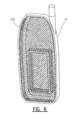
- Fig. 6 is a top plan view of the rear cover 14 of Fig. 2, wherein the EMI shield 150 in the form of the electrically conductive fabric sheet is shown within the interior of the cover.
- the fabric sheet may be placed in the interior as a pre-formed piece conforming to the interior size and shape of the cover 14, or may be fitted into place by insertion by the mold forming the cover by placing the fabric sheet between the mold and the interior of the cover and moving the mold to press the sheet into place in an operation similar to that in making initial molded cover.
- Fig. 7 is an exploded schematic representation of the assembly of the EMI shield and electronic printed circuit board to the interior of the cover of the electronic device.
- the EMI shield fabric sheet 200 is placed in contact with the interior surface 202 of the cover 204 with the adhesive glue drops 206 in facing relationship with the interior surface 202 of the cover 204.
- the electronic circuit board 210 is located and mounted within the cover 204 such that the printed circuit electrical ground reference potential path surfaces 212 come in electrical and mechanical contact with the exposed conductive face 214 of the EMI shield 200, as illustrated schematically in Fig. 5.
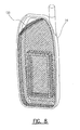
- the EMI shield 150 is shown partially pulled away from the interior of the cover 14 as it might be during the removal process to separate the EMI shield from the cover.
- the fabric sheet comprising the EMI shield is of sufficient strength to resist tearing during the removal process to facilitate separation of the EMI shield from the cover.
- a coating of a conductive polymer paint shown generally as 250, is applied to the surface of the interior area of the cover 14 as shown in Fig. 2.
- the surface of the interior of the cover is treated to modify its adhesion properties to allow the subsequently applied polymer coating to be peeled away from the surface for separation of the polymer coating from the cover.
- the surface of the interior of the cover 14 may be highly polished or waxed, in which case the adhesion properties of the surface are reduced such that the adhesion force between the conductive polymer paint coating and the surface of the interior of the cover is less than the inherent cohesion forces of the conductive polymer paint coating itself to allow peeling of the conductive polymer paint coating from the interior of the wall surface without tearing the polymer coating.
Landscapes
- Engineering & Computer Science (AREA)
- Microelectronics & Electronic Packaging (AREA)
- Signal Processing (AREA)
- Shielding Devices Or Components To Electric Or Magnetic Fields (AREA)
Abstract
Description
Claims (20)
- A cover for an electronic device comprising:an interior chamber formed by intersecting wall surfaces;an EMI shield juxtaposed with said interior wall surfaces and conforming substantially to the size and shape of said interior chamber, said EMI shield further being removable from said interior chamber for separating said cover and said EMI shield into respective individual parts.
- A cover for an electronic device as defined in claim 1, wherein said EMI shield comprises an electrically conductive fabric sheet.
- A cover for an electronic device as defined in claim 2, wherein said electrically conductive fabric sheet is releasably fastened to the surface of said interior wall by an adhesive means applied to a face of said fabric sheet.
- A cover for an electronic device as defined in claim 3, wherein said adhesive means are drops of glue in a spaced relation from one another.
- A cover for an electronic device as defined in claim 3, wherein said adhesive means is an adhesive spray.
- A cover for an electronic device as defined in claim 3, wherein said adhesive means is heat activated.
- A cover for an electronic device as defined in claim 2, wherein said electrically conductive fabric sheet comprises a woven mesh of conductive fibers.
- A cover for an electronic device as defined in claim 7, wherein said conductive fibers comprise silver-coated thread.
- A cover for an electronic device as defined in claim 2, wherein said electrically conductive fabric sheet is pliable.
- A cover for an electronic device as defined in claim 2, wherein said electrically conductive fabric sheet is stretchable.
- A cover for an electronic device as defined in claim 3, wherein said electrically conductive fabric sheet is of sufficient strength to resist tearing during removal from said cover.
- A cover for an electronic device as defined in claim 1, wherein said EMI shield is pre-formed to the size and shape of said interior chamber.
- A cover for an electronic device as defined in claim 1, wherein said cover is molded from a thermoplastic polymer blend.
- A cover for an electronic device as defined in claim 13, wherein said EMI shield is fitted to said interior chamber subsequent to the molding of the cover.
- A cover for an electronic device as defined in claim 1, wherein said EMI shield comprises a coating of a conductive polymer paint applied to an adhesion-modified surface of said interior wall forming said interior chamber, whereby the adhesion force between the conductive polymer paint coating and the surface of said interior wall is less than the inherent cohesion forces of the conductive polymer paint coating itself to allow peeling and separation of said conductive polymer paint coating from the interior wall surfaces.
- A cover for an electronic device as defined in claim 1, further comprising said interior chamber housing electronic circuit components carried on a substrate mounted therein, said substrate having an electrical ground potential surface area, said interior chamber further having bossed regions extending generally away from a rear interior surface of said chamber toward and in proximity with said substrate electrical ground potential surface area to encompass one or more of said electronic circuit components when said substrate is assembled with said cover, wherein said portions of said EMI shield covering said bossed regions are in electrical and mechanical contact with said substrate electrical ground potential surface area.
- An electronic device molded cover comprising an inner area having a major face surface and at least one wall portion extending from said major face surface and defining one or more chambers within said cover, and a releasable EMI shield covering at least a portion of said inner area, whereby said releasable EMI shield facilitates removal from said cover to separate said EMI shield from said cover without substantial contamination of each by the other to facilitate recycling of said EMI shield and said cover into the respective raw material of each.
- A method for providing an EMI shielded electronic device molded cover comprising the steps of:providing an EMI shielding material that is conformable to the shape of the interior of the cover;locating the EMI shielding material in the interior of the cover; andreleasably securing the EMI shielding material to the interior of the cover whereby the EMI shielding material is removable to separate the EMI shielding material from the cover without substantial contamination of each by the other to facilitate recycling of the EMI shielding material and the cover into the respective raw material of each.
- The method for providing an EMI shielding electronic device molded cover as defined in claim 18, wherein the step of providing an EMI shielding material further comprises providing an electrically conductive fabric sheet having an adhesive applied to a face of the fabric sheet.
- The method for providing an EMI shielding electronic device molded cover as defined in claim 18, wherein the step of providing an EMI shielding material further comprises the step of reducing the adhesion properties of the surfaces of the interior of the cover and the step of providing a coating of a conductive polymer paint on the interior surface of the cover.
Applications Claiming Priority (2)
| Application Number | Priority Date | Filing Date | Title |
|---|---|---|---|
| US09/801,277 US6576832B2 (en) | 2001-03-07 | 2001-03-07 | Electronic device molded cover having a releasable EMI shield |
| US801277 | 2001-03-07 |
Publications (2)
| Publication Number | Publication Date |
|---|---|
| EP1239649A2 true EP1239649A2 (en) | 2002-09-11 |
| EP1239649A3 EP1239649A3 (en) | 2003-07-09 |
Family
ID=25180659
Family Applications (1)
| Application Number | Title | Priority Date | Filing Date |
|---|---|---|---|
| EP02251337A Withdrawn EP1239649A3 (en) | 2001-03-07 | 2002-02-26 | Electronic device molded cover having a releasable emi shield |
Country Status (2)
| Country | Link |
|---|---|
| US (1) | US6576832B2 (en) |
| EP (1) | EP1239649A3 (en) |
Cited By (4)
| Publication number | Priority date | Publication date | Assignee | Title |
|---|---|---|---|---|
| WO2009053121A1 (en) * | 2007-10-26 | 2009-04-30 | HÄNSEL VERBUNDTECHNIK GmbH | Textile fabric for a vehicle seat cover |
| FR2952273A1 (en) * | 2009-11-03 | 2011-05-06 | Sierra Wireless Inc | Mother board for radio communication equipment e.g. radio telephone, has electronic component formed on transferring surface of electronic circuit e.g. radio communication module, and electromagnetic shielding that forms cavity |
| CN104012187A (en) * | 2011-12-07 | 2014-08-27 | 皇家飞利浦有限公司 | Electronic Textile With Means For Facilitating Waste Sorting |
| DE102018204625A1 (en) * | 2018-03-27 | 2019-10-02 | Siemens Aktiengesellschaft | Housing for an inverter, power amplifier of an inverter with such a housing, inverter and aircraft with an inverter |
Families Citing this family (35)
| Publication number | Priority date | Publication date | Assignee | Title |
|---|---|---|---|---|
| US6711387B1 (en) * | 2000-10-13 | 2004-03-23 | Andrew T. Lungley | Radiation-shielding mobile phone case device |
| WO2004089053A1 (en) * | 2003-04-04 | 2004-10-14 | Per Jan Neergasrd | Invention concerning the removal of radiation from mobile phones and other electrical/electronic appliances |
| US6940010B2 (en) * | 2003-06-30 | 2005-09-06 | Nokia Corporation | Electromagnetic interference shield and method of making the same |
| US20060046337A1 (en) * | 2004-09-02 | 2006-03-02 | Honeywell International Inc. | Metalized plastic seal |
| JP4511408B2 (en) * | 2005-04-18 | 2010-07-28 | 富士通株式会社 | Display module and portable terminal device |
| KR101175728B1 (en) * | 2006-01-20 | 2012-08-22 | 삼성전자주식회사 | Apparatus for shielding the electromagnetic interference of a display module and method for manufacturing thereof |
| US7733659B2 (en) * | 2006-08-18 | 2010-06-08 | Delphi Technologies, Inc. | Lightweight audio system for automotive applications and method |
| CN101325620A (en) * | 2007-06-14 | 2008-12-17 | 鸿富锦精密工业(深圳)有限公司 | Anti-radiation mobile phone case |
| TWI396499B (en) * | 2008-01-18 | 2013-05-11 | Asustek Comp Inc | Housing with shielding function and manufacturing method therefor and electronic device using the same |
| KR20100135294A (en) * | 2008-04-17 | 2010-12-24 | 라이르드 테크놀로지스, 아이엔씨 | Integrated Antenna and EM Eye Shield Supporting Member for Portable Communication Terminal |
| CN101640995B (en) * | 2008-07-31 | 2012-07-04 | 深圳富泰宏精密工业有限公司 | Electronic device shell |
| US8657662B2 (en) * | 2008-09-04 | 2014-02-25 | Patent Investment & Licensing Company | Gaming device having variable speed of play |
| US9172134B2 (en) | 2008-11-06 | 2015-10-27 | Antenna79, Inc. | Protective cover for a wireless device |
| US8957813B2 (en) | 2009-03-13 | 2015-02-17 | Pong Research Corporation | External case for redistribution of RF radiation away from wireless communication device user and wireless communication device incorporating RF radiation redistribution elements |
| CN201663225U (en) | 2008-11-06 | 2010-12-01 | 黄耀辉 | Antenna embedded into battery, wireless device and intelligent outer shell of wireless device |
| US8214003B2 (en) | 2009-03-13 | 2012-07-03 | Pong Research Corporation | RF radiation redirection away from portable communication device user |
| TWI388273B (en) * | 2008-12-19 | 2013-03-01 | Hon Hai Prec Ind Co Ltd | Electronic fabric and electronic device using thereof |
| US9628890B2 (en) | 2009-06-10 | 2017-04-18 | Apple Inc. | Electronic device accessories formed from intertwined fibers |
| DE102009037948A1 (en) * | 2009-08-18 | 2011-02-24 | Bartec Gmbh | Housing for an electrical device |
| KR101032252B1 (en) * | 2009-10-23 | 2011-05-02 | 삼성전기주식회사 | Video camera and electronic device including the same |
| US10071802B2 (en) * | 2009-12-02 | 2018-09-11 | Ums Skeldar Sweden Ab | Mounting device for electronic components in UAV helicopters |
| WO2012015981A1 (en) * | 2010-07-27 | 2012-02-02 | Speculative Product Design, Llc. | A case for enclosing and remaining attached to a mobile communication device with applied fabric |
| US8559869B2 (en) | 2011-09-21 | 2013-10-15 | Daniel R. Ash, JR. | Smart channel selective repeater |
| US20130099956A1 (en) * | 2011-10-24 | 2013-04-25 | Lsi Corporation | Apparatus to reduce specific absorption rate |
| US9838060B2 (en) | 2011-11-02 | 2017-12-05 | Antenna79, Inc. | Protective cover for a wireless device |
| US20130137327A1 (en) * | 2011-11-25 | 2013-05-30 | Kai-Hsi Tseng | Anti-interference cover made of a compound material for an electronic product |
| USD750057S1 (en) * | 2013-07-24 | 2016-02-23 | Jason Rhoades | Personal mobile device radiation shield |
| US9229483B1 (en) * | 2014-08-15 | 2016-01-05 | Shahriar Davaran | Radiation inhibiting personal electronics case |
| US9529389B1 (en) * | 2014-09-25 | 2016-12-27 | Amazon Technologies, Inc. | Variable plated device enclosure |
| WO2016111512A1 (en) | 2015-01-09 | 2016-07-14 | Samsung Electronics Co., Ltd. | Semiconductor package and method of manufacturing the same |
| US10141968B2 (en) | 2016-07-29 | 2018-11-27 | Rowtan Technologies, Llc | Device for reflecting, deflecting, and/or absorbing electromagentic radiation emitted from an electronic device and method therefor |
| US10630331B2 (en) | 2016-07-29 | 2020-04-21 | Rowtan Technologies Llc | Devices for reflecting, deflecting, and/or absorbing electromagnetic radiation emitted from an electronic device and methods therefor |
| CN106393709A (en) * | 2016-09-27 | 2017-02-15 | 广东欧珀移动通信有限公司 | Mobile terminal, back cover, jig and bonding method of cloth and plastic |
| WO2018126247A2 (en) | 2017-01-02 | 2018-07-05 | Mojoose, Inc. | Automatic signal strength indicator and automatic antenna switch |
| US12185515B2 (en) * | 2021-12-16 | 2024-12-31 | AISIN Technical Center of America, Inc. | Polymer-graphene electronic component housing |
Family Cites Families (9)
| Publication number | Priority date | Publication date | Assignee | Title |
|---|---|---|---|---|
| DE3631696A1 (en) * | 1986-09-18 | 1988-04-07 | Wilde Membran Impuls Tech | Metallised, textile sheet-like structure as a guard against electromagnetic radiation in electrical and electronic equipment and components |
| US5676812A (en) * | 1990-03-24 | 1997-10-14 | Canon Kabushiki Kaisha | Electronic equipment with an adhesive member to intercept electromagnetic waves |
| US5596170A (en) * | 1993-11-09 | 1997-01-21 | International Business Machines Corporation | Flexible dome electrical contact |
| JP2776753B2 (en) * | 1994-11-24 | 1998-07-16 | 埼玉日本電気株式会社 | Plastic shielded housing |
| JPH1074613A (en) * | 1996-08-30 | 1998-03-17 | Tokin Corp | Tape, adhesive tape and self-bonding tape |
| JP3900559B2 (en) * | 1996-09-19 | 2007-04-04 | 大同特殊鋼株式会社 | Magnetic shielding sheet, manufacturing method thereof, and cable using the same |
| US6275683B1 (en) * | 1998-01-12 | 2001-08-14 | Ericsson Inc. | Interchangeable shield for a radio communication device |
| AU6000799A (en) * | 1998-09-30 | 2000-04-17 | Hihakaikensa Co., Ltd | Shield against radio wave or magnetic wave and shielding structure for the edge |
| US6243274B1 (en) * | 2000-04-20 | 2001-06-05 | Redcom Laboratories, Inc. | Shields for electronic components with ready access to shielded components |
-
2001
- 2001-03-07 US US09/801,277 patent/US6576832B2/en not_active Expired - Lifetime
-
2002
- 2002-02-26 EP EP02251337A patent/EP1239649A3/en not_active Withdrawn
Cited By (6)
| Publication number | Priority date | Publication date | Assignee | Title |
|---|---|---|---|---|
| WO2009053121A1 (en) * | 2007-10-26 | 2009-04-30 | HÄNSEL VERBUNDTECHNIK GmbH | Textile fabric for a vehicle seat cover |
| FR2952273A1 (en) * | 2009-11-03 | 2011-05-06 | Sierra Wireless Inc | Mother board for radio communication equipment e.g. radio telephone, has electronic component formed on transferring surface of electronic circuit e.g. radio communication module, and electromagnetic shielding that forms cavity |
| CN104012187A (en) * | 2011-12-07 | 2014-08-27 | 皇家飞利浦有限公司 | Electronic Textile With Means For Facilitating Waste Sorting |
| CN104012187B (en) * | 2011-12-07 | 2015-11-25 | 皇家飞利浦有限公司 | There is the electronic textile of the device being convenient to refuse classification |
| DE102018204625A1 (en) * | 2018-03-27 | 2019-10-02 | Siemens Aktiengesellschaft | Housing for an inverter, power amplifier of an inverter with such a housing, inverter and aircraft with an inverter |
| US11450621B2 (en) | 2018-03-27 | 2022-09-20 | Rolls-Royce Deutschland Ltd & Co Kg | Housing for a converter, output stage of a converter having such a housing, converter, and aircraft having a converter |
Also Published As
| Publication number | Publication date |
|---|---|
| US20020125025A1 (en) | 2002-09-12 |
| EP1239649A3 (en) | 2003-07-09 |
| US6576832B2 (en) | 2003-06-10 |
Similar Documents
| Publication | Publication Date | Title |
|---|---|---|
| US6576832B2 (en) | Electronic device molded cover having a releasable EMI shield | |
| EP0976311B1 (en) | A shielding housing and a method of producing a shielding housing | |
| US5150282A (en) | Electromagnetic shielding structure of high-frequency circuit arrangements | |
| US6624432B1 (en) | EMI containment apparatus | |
| EP0806892B1 (en) | Faraday cage | |
| US5596487A (en) | Apparatus for RF shielding radio circuitry | |
| CA2402633C (en) | Conforming shielded form for electronic component assemblies and methods for making and using same | |
| US5844166A (en) | Lattice RF shield | |
| CA2160751C (en) | Shielded switch | |
| JPH08153986A (en) | Shield case mounting structure | |
| US5825606A (en) | Communications set with electrostatic protection | |
| EP0806891B1 (en) | A lid assembly for shielding electronic components from EMI/RFI interferences | |
| US20070121307A1 (en) | EMI/RFI shield for electronic device | |
| KR20030076470A (en) | An apparutus and method for EMI and ESD shielding using plastic can in borad of electronic equipment | |
| KR100673531B1 (en) | Thin electromagnetic shielding tape, electromagnetic shielding structure using the same and manufacturing method thereof | |
| WO1999043191A1 (en) | Housing with shielding properties and method for making it | |
| KR20040095039A (en) | Emi shielding apparatus for portable terminal | |
| JPH05299873A (en) | Wave absorbing method for article, wave absorbing structure for article printed board ferrite sheet used for wave absorption and manufacture thereof | |
| CN209930822U (en) | Shielding device | |
| JPS63300599A (en) | Electromagnetic shielding structure of communication equipment | |
| JPH04150097A (en) | Enclosure of electronic equipment | |
| WO2003045124A2 (en) | A replaceable shield can | |
| KR20030079196A (en) | Conductive sheet and method for manufacturing the same | |
| HK1027714B (en) | A shielding housing and a method of producing a shielding housing |
Legal Events
| Date | Code | Title | Description |
|---|---|---|---|
| PUAI | Public reference made under article 153(3) epc to a published international application that has entered the european phase |
Free format text: ORIGINAL CODE: 0009012 |
|
| AK | Designated contracting states |
Kind code of ref document: A2 Designated state(s): AT BE CH CY DE DK ES FI FR GB GR IE IT LI LU MC NL PT SE TR |
|
| AX | Request for extension of the european patent |
Free format text: AL;LT;LV;MK;RO;SI |
|
| RIN1 | Information on inventor provided before grant (corrected) |
Inventor name: UUSIMAEKI, MATTI Inventor name: SVARFVAR, BROR |
|
| PUAL | Search report despatched |
Free format text: ORIGINAL CODE: 0009013 |
|
| AK | Designated contracting states |
Designated state(s): AT BE CH CY DE DK ES FI FR GB GR IE IT LI LU MC NL PT SE TR |
|
| AX | Request for extension of the european patent |
Extension state: AL LT LV MK RO SI |
|
| AKX | Designation fees paid | ||
| REG | Reference to a national code |
Ref country code: DE Ref legal event code: 8566 |
|
| STAA | Information on the status of an ep patent application or granted ep patent |
Free format text: STATUS: THE APPLICATION IS DEEMED TO BE WITHDRAWN |
|
| 18D | Application deemed to be withdrawn |
Effective date: 20040110 |