EP1239338A2 - Color image forming apparatus - Google Patents
Color image forming apparatus Download PDFInfo
- Publication number
- EP1239338A2 EP1239338A2 EP02251638A EP02251638A EP1239338A2 EP 1239338 A2 EP1239338 A2 EP 1239338A2 EP 02251638 A EP02251638 A EP 02251638A EP 02251638 A EP02251638 A EP 02251638A EP 1239338 A2 EP1239338 A2 EP 1239338A2
- Authority
- EP
- European Patent Office
- Prior art keywords
- image
- transferring
- forming apparatus
- image supporting
- belt
- Prior art date
- Legal status (The legal status is an assumption and is not a legal conclusion. Google has not performed a legal analysis and makes no representation as to the accuracy of the status listed.)
- Granted
Links
Images

Classifications
-
- G—PHYSICS
- G03—PHOTOGRAPHY; CINEMATOGRAPHY; ANALOGOUS TECHNIQUES USING WAVES OTHER THAN OPTICAL WAVES; ELECTROGRAPHY; HOLOGRAPHY
- G03G—ELECTROGRAPHY; ELECTROPHOTOGRAPHY; MAGNETOGRAPHY
- G03G15/00—Apparatus for electrographic processes using a charge pattern
- G03G15/01—Apparatus for electrographic processes using a charge pattern for producing multicoloured copies
- G03G15/0142—Structure of complete machines
- G03G15/0178—Structure of complete machines using more than one reusable electrographic recording member, e.g. one for every monocolour image
- G03G15/0194—Structure of complete machines using more than one reusable electrographic recording member, e.g. one for every monocolour image primary transfer to the final recording medium
-
- G—PHYSICS
- G03—PHOTOGRAPHY; CINEMATOGRAPHY; ANALOGOUS TECHNIQUES USING WAVES OTHER THAN OPTICAL WAVES; ELECTROGRAPHY; HOLOGRAPHY
- G03G—ELECTROGRAPHY; ELECTROPHOTOGRAPHY; MAGNETOGRAPHY
- G03G2215/00—Apparatus for electrophotographic processes
- G03G2215/01—Apparatus for electrophotographic processes for producing multicoloured copies
- G03G2215/0103—Plural electrographic recording members
- G03G2215/0119—Linear arrangement adjacent plural transfer points
Definitions
- a recording medium such as paper
- a belt member, a drum member or the like toner images on a plurality of image supporting members are sequentially transferred to the recording medium so as to superpose the multiple-color toner images thereon to provide a color image.
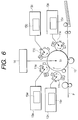
- numeral 12 denotes an intermediate transferring drum, and four different-color photoconductive drums 11 (Y, M, C, and K) are brought into contact with the intermediate transferring drum 12.
- a yellow toner image provided by the photoconductive drum 11Y, a magenta toner image provided by the photoconductive drum 11M, a cyan toner image provided by the photoconductive drum 11C, and a black toner image provided by the photoconductive drum 11K are sequentially transferred to the intermediate transferring drum 12 to form a full-color toner image, which is then transferred to a recording medium P.
- a color image forming apparatus comprising:
- the apparatus further comprises:
- a color image forming apparatus comprising:
- both of the first gear train and the second gear train are driven by the single drive source, the mechanical structure is remarkably simplified which allows for the apparatus size to be reduced.
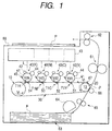
- an intermediate transferring belt 30 is wound on a drive roller 10 and a driven roller 20 and circulated in the arrow direction shown (counterclockwise).
- a plurality of (four) single-color toner image formers 40 (Y, C, M, and K) are brought into contact with the intermediate transferring belt 30, and color toner images provided by the plurality of single-color toner image formers 40 are sequentially transferred to the intermediate transferring belt 30 by separate transferring members 51, 52, 53, and 54.
- Transfer points (primary transferring points) are denoted by T1Y, T1C, T1M, and T1K.
- the full-color toner image provided by primarily transferred toner images in sequence to the intermediate transferring belt 30 so as to be superposed thereon is secondarily transferred to a recording medium P such as paper at a secondary transferring point T2 and is fixed on the recording medium P as it passes through a fixing roller pair 61 of a fixing section.
- the recording medium P with the fixed image is then is ejected onto a paper ejection tray 68 formed on the top of the apparatus by a paper ejection roller pair 62.
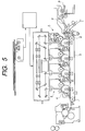
- the velocity Vt (circulating velocity) of the transferring belt 30 is higher than the circumferential velocity Vdi of each of the image supporting members 41 (Vd1, Vd2, Vd3, Vd4). That is, Vt > Vdi.
- the tensed state of the intermediate transferring belt 30 becomes stable not only between the drive roller 10 and the image supporting member 41 (K) adjacent to the drive roller 10, but also between the respective image supporting members.
- every image supporting member positioned upstream acts reliably as a brake with respect to a downstream portion of the transferring belt 30 positioned between the adjacent image supporting members 41, so that the tensed state of the transferring belt 30 also becomes stable between the image supporting members 41.
- the image supporting member 41 (M) acts as a brake with respect to the portion of the transferring belt 30 situated between the abutment point T1K and an abutment point T1M at which the image supporting member 41 (M) abuts on the transferring belt 30, so that the tensed state of that portion of the transferring belt 30 becomes stable.
- the image supporting member 41 (C) acts as a brake with respect to a portion of the transferring belt 30 situated between the abutment point T1M and an abutment point T1C at which the image supporting member 41 (C) abuts on the transferring belt 30, so that the tensed state of that portion of the transferring belt 30 becomes stable.
- an initial tension given to the transferring belt 30 can be lessened because the tensed state of the transferring belt 30 becomes stable when the image forming apparatus is activated (when the image supporting members 41 and the transferring belt 30 are driven).
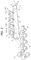
- the apparatus has a first gear train GD for driving the image supporting members 41 and a second gear train GT for driving the intermediate transferring belt 30. Both gear trains are driven by a single drive source gear GM.
- the second gear train GT is driven through the first gear train GD so that the gear trains started from the drive source gear GM to a drive gear Gt at the last stage is implemented as one gear train with no branch.
- a gear Gd4 meshes with the gear Gd3 through an idle gear Ga3, whereby the image supporting member 41(K) is driven at the circumferential velocity Vd4 (>Vd3).
- the drive gear Gt meshes with the gear Gd4 through idle gears Gat1 and Gat2, whereby the drive roller 10 is driven at the circumferential velocity Vt (>Vd4).
- the second gear train GT (gears Gat1, Gat2, and Gt) is driven through the first gear train GD (gears Gd1, Ga1, Gd2, Ga2, Gd3, Ga3, and Gd4) and the gear train from the drive source gear GM to the drive gear Gt at the last stage is implemented as one gear train with no branch.
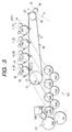
- the image supporting member 41 receives a force Fd (acceleration force attempting to rotate the image supporting member 41 at a higher rate than a predetermined number of revolutions (at equal velocity to the circulation velocity of the intermediate transferring belt 30) from the transferring belt 30 as a reaction.
- Fd acceleration force attempting to rotate the image supporting member 41 at a higher rate than a predetermined number of revolutions (at equal velocity to the circulation velocity of the intermediate transferring belt 30) from the transferring belt 30 as a reaction.
- Fd acceleration force attempting to rotate the image supporting member 41 at a higher rate than a predetermined number of revolutions (at equal velocity to the circulation velocity of the intermediate transferring belt 30) from the transferring belt 30 as a reaction.
- the forces Ft and Fd occur in each abutment point (T1).
- the image supporting member 41 (K) is taken as a representative.
- the force Fd is transmitted to the gear Gd4 via the image supporting member 41 (K).
- the first gear train GT is driven through the second gear train GD so that the gear train from the drive source gear GM to the drive gear Gt at the last stage is implemented as one gear train with no branch.
- this arrangement makes it impossible that the force Fd acts as a force attempting to rotate the gears Gd4 and Ga3 at a higher rate than the predetermined number of revolutions (at equal velocity to the circumferential velocity of the transferring member 30). Even if backlash S is about to occur in the abutment point b between the gears Gd4 and Ga3 in such a case as shown in Fig.
- the velocity relationship that Vt > Vdi described above can be reliably provided so that the variation in the difference between the circumferential velocity of the image supporting member 41 and the circumferential velocity of the transferring member 30 can be reliably minimized. Accordingly, the transferring condition from the image supporting member 41 to the transferring member 30 can be reliably stabilized, so that a fine image may be obtained.
- the color image forming apparatus wherein a plurality of the image supporting members are provided for supporting different-color images to be once transferred onto a transferring member in sequence to form a color image thereon, or in a color image forming apparatus wherein different-color images are directly transferred onto a recording medium held on a transferring member to form a color image thereon (not shown), not only the driving mechanism for the image supporting members and the transferring member is remarkably simplified, but also a fine color image with no color shift can be reliably obtained.
- the secondary transferring point T2 for transferring a color toner image from the intermediate transferring belt 30 to the recording medium P is formed in the part of winding the intermediate transferring belt 30 around the driven roller 20, so that the recording medium P passes through the secondary transferring point T2 upward from the lower side.
- the driven roller 20 is rotatably supported at both ends by bearing members (not shown) such that a core shaft thereof is not displaced, to make the secondary transferring point T2 stable.
- the cleaning blade 67 for removing the remaining toner on the intermediate transferring belt 30 after secondary transfer abuts the intermediate transferring belt 30 in the part of winding the intermediate transferring belt 30 around the driven roller 20.
- the intermediate transferring belt 30 may have at least one of the following conditions:
- the remaining toner from transfer exists on the image supporting member 41 and accumulates gradually thereon, causing so-called filming to occur as one factor of degradation of the image quality.
- the surface of the image supporting member 41 is slightly cut and is always refreshed because of the difference between the circumferential velocity of the transferring member 30 and the circumferential velocity of the image supporting member 41. Therefore, filming is prevented so that the image quality is maintained.
- an intermediate transfer drum may be used as the transferring member instead of the above-described intermediate transfer belt.
- a member for holding and transporting a recording medium thereon may be used as the transferring member.
- each of the transferring members 51, 52, 53, and 54 in the above embodiment is implemented as a transfer blade
- the transferring members may also be implemented, for example, as a corona transfer device.
- the drive roller 10 may be implemented as a tension roller and/or meander regulation roller.
Landscapes
- Physics & Mathematics (AREA)
- General Physics & Mathematics (AREA)
- Electrostatic Charge, Transfer And Separation In Electrography (AREA)
- Color Electrophotography (AREA)
- Ink Jet (AREA)
- Photographic Developing Apparatuses (AREA)
Abstract
Description
Claims (12)
- A color image forming apparatus, comprising:a drive roller and a driven roller;a looped belt member stretched and circulated by at least the drive roller and the driven roller so as to have a tensed side and a slack side; anda plurality of image supporting members, each supporting a single color toner image thereon, and abutting onto the tensed side of the belt member to define a transferring position at which the toner image is transferred onto either the belt member or a recording medium held by the belt member, while being rotated, wherein:a circumferential velocity of each image supporting member is determined so as to be lower than a circulation velocity of the belt member; andthe circumferential velocity of an image supporting member which is further from the driving roller is lower than the circumferential velocity of an image supporting member which is closer to the driving roller.
- The color image forming apparatus as set forth in claim 1, further comprising:a first gear train, which rotates the image supporting members;a second gear train, which rotates the drive roller to circulate the belt member, while being connected to the first gear train with no branch; anda single drive source, which drives the first gear train to thereby drive the second gear train.
- The color image forming apparatus as set forth in claim 1, wherein a surface hardness of the belt member is greater than a surface hardness of the image supporting members.
- The color image forming apparatus as set forth in claim 1, wherein a surface roughness of the belt member is greater than a surface roughness of the image supporting members.
- The color image forming apparatus as set forth in claim 1, wherein the belt member includes an abrasive surface.
- The color image forming apparatus as set forth in claim 1, further comprising a cleaning member which abuts against a part of the belt member which is wound on the driven roller, to remove toner remained on the belt member.
- The color image forming apparatus as set forth in claim 1, further comprising a secondary transfer position, formed on a part of the belt member which is wound on the driven roller, at which the toner images transferred from the image supporting members are secondarily transferred to a recording medium,
wherein the recording medium passes through the secondary transfer position upward from a lower part of the apparatus. - The image forming apparatus as set forth in claim 7, further comprising a fixing section at which the secondarily transferred toner image is fixed on the recording medium,
wherein the fixing section is placed above the plurality of image supporting members. - A color image forming apparatus, comprising:wherein a circumferential velocity of each image supporting member is determined so as to be lower than a circulation velocity of the transferring member.a transferring member;a plurality of image supporting members, each supporting a single color toner image thereon, and abutting onto the transferring member to define a transferring position at which the toner image is transferred onto either the transferring member or a recording medium held by the transferring member, while being rotated;a first gear train, which rotates the image supporting members;a second gear train, which rotates the transferring member, while being connected to the first gear train with no branch; anda single drive source, which drives the first gear train to thereby drive the second gear train,
- The color image forming apparatus as set forth in claim 9, wherein a surface hardness of the transferring member is greater than a surface hardness of the image supporting members.
- The color image forming apparatus as set forth in claim 9, wherein a surface roughness of the transferring member is greater than a surface roughness of the image supporting members.
- The color image forming apparatus as set forth in claim 9, wherein the transferring member includes an abrasive surface.
Applications Claiming Priority (4)
| Application Number | Priority Date | Filing Date | Title |
|---|---|---|---|
| JP2001067576 | 2001-03-09 | ||
| JP2001067576A JP2002268316A (en) | 2001-03-09 | 2001-03-09 | Color image forming equipment |
| JP2001106783 | 2001-04-05 | ||
| JP2001106783A JP2002304038A (en) | 2001-04-05 | 2001-04-05 | Color image forming equipment |
Publications (3)
| Publication Number | Publication Date |
|---|---|
| EP1239338A2 true EP1239338A2 (en) | 2002-09-11 |
| EP1239338A3 EP1239338A3 (en) | 2004-03-31 |
| EP1239338B1 EP1239338B1 (en) | 2006-11-22 |
Family
ID=26610996
Family Applications (1)
| Application Number | Title | Priority Date | Filing Date |
|---|---|---|---|
| EP02251638A Expired - Lifetime EP1239338B1 (en) | 2001-03-09 | 2002-03-07 | Color image forming apparatus |
Country Status (6)
| Country | Link |
|---|---|
| US (1) | US6625411B2 (en) |
| EP (1) | EP1239338B1 (en) |
| CN (1) | CN1232888C (en) |
| AT (1) | ATE346327T1 (en) |
| DE (1) | DE60216171T2 (en) |
| TW (1) | TW591350B (en) |
Families Citing this family (6)
| Publication number | Priority date | Publication date | Assignee | Title |
|---|---|---|---|---|
| US6708013B2 (en) * | 2001-06-14 | 2004-03-16 | Seiko Epson Corporation | Color image forming apparatus |
| JP2005080378A (en) * | 2003-08-29 | 2005-03-24 | Konica Minolta Business Technologies Inc | Driving unit, image forming apparatus |
| JP4748983B2 (en) * | 2004-12-28 | 2011-08-17 | 京セラミタ株式会社 | Image forming apparatus |
| KR100667828B1 (en) * | 2005-11-03 | 2007-01-11 | 삼성전자주식회사 | An image transfer unit, an electrophotographic image forming apparatus having the same, and an electrophotographic image forming method |
| JP4863004B2 (en) * | 2006-12-27 | 2012-01-25 | 富士ゼロックス株式会社 | Conveying apparatus and image forming apparatus |
| JP2015087400A (en) * | 2013-10-28 | 2015-05-07 | コニカミノルタ株式会社 | Image forming apparatus |
Family Cites Families (15)
| Publication number | Priority date | Publication date | Assignee | Title |
|---|---|---|---|---|
| JPS61156161A (en) * | 1984-12-28 | 1986-07-15 | Ricoh Co Ltd | Color recording device |
| JPH04324881A (en) | 1991-04-25 | 1992-11-13 | Fujitsu Ltd | image recording device |
| DE69427779D1 (en) * | 1993-03-05 | 2001-08-23 | Toshiba Kawasaki Kk | Imaging device |
| US5508789A (en) * | 1994-11-22 | 1996-04-16 | Xerox Corporation | Apparatus and method to control and calibrate deliberate speed mismatch in color IOTs |
| JP3186559B2 (en) * | 1995-12-25 | 2001-07-11 | カシオ電子工業株式会社 | Image forming device |
| US6016417A (en) * | 1996-11-08 | 2000-01-18 | Fuji Xerox, Co., Ltd | Intermediate transfer medium, method for producing the same and image forming device using the same |
| JP3175633B2 (en) * | 1997-05-06 | 2001-06-11 | 富士ゼロックス株式会社 | Image forming device |
| JPH1115226A (en) * | 1997-06-23 | 1999-01-22 | Fuji Xerox Co Ltd | Color image forming device |
| JP3455067B2 (en) * | 1997-07-01 | 2003-10-06 | シャープ株式会社 | Color image forming equipment |
| US5970286A (en) * | 1997-08-01 | 1999-10-19 | Casio Computerco., Ltd. | Image forming apparatus and image forming unit with an improved phase adjustment means |
| JPH1165222A (en) * | 1997-08-11 | 1999-03-05 | Ricoh Co Ltd | Color image forming equipment |
| EP0943970B1 (en) * | 1997-09-29 | 2004-12-01 | Matsushita Electric Industrial Co., Ltd. | Multiple image forming apparatus |
| US6463247B1 (en) * | 1999-06-15 | 2002-10-08 | Matsushita Electric Industrial Co., Ltd. | Color image formation apparatus using plural photosensitive drums |
| US6453139B2 (en) * | 2000-01-18 | 2002-09-17 | Canon Kabushiki Kaisha | Image forming apparatus |
| JP2002014511A (en) * | 2000-06-28 | 2002-01-18 | Matsushita Electric Ind Co Ltd | Color image forming equipment |
-
2002
- 2002-03-07 AT AT02251638T patent/ATE346327T1/en not_active IP Right Cessation
- 2002-03-07 EP EP02251638A patent/EP1239338B1/en not_active Expired - Lifetime
- 2002-03-07 DE DE60216171T patent/DE60216171T2/en not_active Expired - Lifetime
- 2002-03-08 TW TW091104414A patent/TW591350B/en not_active IP Right Cessation
- 2002-03-08 US US10/092,723 patent/US6625411B2/en not_active Expired - Fee Related
- 2002-03-08 CN CNB021070164A patent/CN1232888C/en not_active Expired - Fee Related
Also Published As
| Publication number | Publication date |
|---|---|
| EP1239338B1 (en) | 2006-11-22 |
| ATE346327T1 (en) | 2006-12-15 |
| EP1239338A3 (en) | 2004-03-31 |
| TW591350B (en) | 2004-06-11 |
| CN1374567A (en) | 2002-10-16 |
| US20020141782A1 (en) | 2002-10-03 |
| DE60216171D1 (en) | 2007-01-04 |
| DE60216171T2 (en) | 2007-03-08 |
| US6625411B2 (en) | 2003-09-23 |
| CN1232888C (en) | 2005-12-21 |
Similar Documents
| Publication | Publication Date | Title |
|---|---|---|
| EP1239337B1 (en) | Colour image forming apparatus | |
| US20020085864A1 (en) | Belt stretcher and color image formation apparatus incorporating the same | |
| US20100278560A1 (en) | Image forming apparatus | |
| EP1239338B1 (en) | Color image forming apparatus | |
| JP2009175667A (en) | Driving force transmission device and image forming apparatus having the same | |
| JP2005157169A (en) | Image forming apparatus and process unit | |
| CN100437379C (en) | Color image forming apparatus | |
| JP2002268323A (en) | Color image forming equipment | |
| JP2002304063A (en) | Image forming device | |
| JP4863004B2 (en) | Conveying apparatus and image forming apparatus | |
| JP2002304038A (en) | Color image forming equipment | |
| JPH11316505A (en) | Image forming device | |
| JP2002268324A (en) | Color image forming equipment | |
| JP3293371B2 (en) | Image forming device | |
| JP2002268325A (en) | Color imaging apparatus | |
| JP2005215126A (en) | Image forming apparatus | |
| JP4088044B2 (en) | Color image forming apparatus | |
| JP3858628B2 (en) | Image forming apparatus | |
| JP3525711B2 (en) | Image forming device | |
| JPH09160384A (en) | Image forming device | |
| JP2001265165A (en) | Image forming device and drive force transmitting device | |
| JP2002123129A (en) | Image forming device | |
| JP2001134108A (en) | Image forming device | |
| JP2003076217A (en) | Color image forming equipment | |
| JP3818088B2 (en) | Color image forming apparatus |
Legal Events
| Date | Code | Title | Description |
|---|---|---|---|
| PUAI | Public reference made under article 153(3) epc to a published international application that has entered the european phase |
Free format text: ORIGINAL CODE: 0009012 |
|
| AK | Designated contracting states |
Kind code of ref document: A2 Designated state(s): AT BE CH CY DE DK ES FI FR GB GR IE IT LI LU MC NL PT SE TR |
|
| AX | Request for extension of the european patent |
Free format text: AL;LT;LV;MK;RO;SI |
|
| PUAL | Search report despatched |
Free format text: ORIGINAL CODE: 0009013 |
|
| AK | Designated contracting states |
Kind code of ref document: A3 Designated state(s): AT BE CH CY DE DK ES FI FR GB GR IE IT LI LU MC NL PT SE TR |
|
| AX | Request for extension of the european patent |
Extension state: AL LT LV MK RO SI |
|
| 17P | Request for examination filed |
Effective date: 20040831 |
|
| AKX | Designation fees paid |
Designated state(s): AT BE CH CY DE DK ES FI FR GB GR IE IT LI LU MC NL PT SE TR |
|
| 17Q | First examination report despatched |
Effective date: 20050218 |
|
| GRAP | Despatch of communication of intention to grant a patent |
Free format text: ORIGINAL CODE: EPIDOSNIGR1 |
|
| GRAS | Grant fee paid |
Free format text: ORIGINAL CODE: EPIDOSNIGR3 |
|
| GRAA | (expected) grant |
Free format text: ORIGINAL CODE: 0009210 |
|
| AK | Designated contracting states |
Kind code of ref document: B1 Designated state(s): AT BE CH CY DE DK ES FI FR GB GR IE IT LI LU MC NL PT SE TR |
|
| PG25 | Lapsed in a contracting state [announced via postgrant information from national office to epo] |
Ref country code: IT Free format text: LAPSE BECAUSE OF FAILURE TO SUBMIT A TRANSLATION OF THE DESCRIPTION OR TO PAY THE FEE WITHIN THE PRESCRIBED TIME-LIMIT;WARNING: LAPSES OF ITALIAN PATENTS WITH EFFECTIVE DATE BEFORE 2007 MAY HAVE OCCURRED AT ANY TIME BEFORE 2007. THE CORRECT EFFECTIVE DATE MAY BE DIFFERENT FROM THE ONE RECORDED. Effective date: 20061122 Ref country code: CH Free format text: LAPSE BECAUSE OF FAILURE TO SUBMIT A TRANSLATION OF THE DESCRIPTION OR TO PAY THE FEE WITHIN THE PRESCRIBED TIME-LIMIT Effective date: 20061122 Ref country code: LI Free format text: LAPSE BECAUSE OF FAILURE TO SUBMIT A TRANSLATION OF THE DESCRIPTION OR TO PAY THE FEE WITHIN THE PRESCRIBED TIME-LIMIT Effective date: 20061122 Ref country code: BE Free format text: LAPSE BECAUSE OF FAILURE TO SUBMIT A TRANSLATION OF THE DESCRIPTION OR TO PAY THE FEE WITHIN THE PRESCRIBED TIME-LIMIT Effective date: 20061122 Ref country code: AT Free format text: LAPSE BECAUSE OF FAILURE TO SUBMIT A TRANSLATION OF THE DESCRIPTION OR TO PAY THE FEE WITHIN THE PRESCRIBED TIME-LIMIT Effective date: 20061122 Ref country code: FI Free format text: LAPSE BECAUSE OF FAILURE TO SUBMIT A TRANSLATION OF THE DESCRIPTION OR TO PAY THE FEE WITHIN THE PRESCRIBED TIME-LIMIT Effective date: 20061122 Ref country code: NL Free format text: LAPSE BECAUSE OF FAILURE TO SUBMIT A TRANSLATION OF THE DESCRIPTION OR TO PAY THE FEE WITHIN THE PRESCRIBED TIME-LIMIT Effective date: 20061122 |
|
| REG | Reference to a national code |
Ref country code: GB Ref legal event code: FG4D |
|
| REG | Reference to a national code |
Ref country code: CH Ref legal event code: EP |
|
| REG | Reference to a national code |
Ref country code: IE Ref legal event code: FG4D |
|
| REF | Corresponds to: |
Ref document number: 60216171 Country of ref document: DE Date of ref document: 20070104 Kind code of ref document: P |
|
| PG25 | Lapsed in a contracting state [announced via postgrant information from national office to epo] |
Ref country code: SE Free format text: LAPSE BECAUSE OF FAILURE TO SUBMIT A TRANSLATION OF THE DESCRIPTION OR TO PAY THE FEE WITHIN THE PRESCRIBED TIME-LIMIT Effective date: 20070222 Ref country code: DK Free format text: LAPSE BECAUSE OF FAILURE TO SUBMIT A TRANSLATION OF THE DESCRIPTION OR TO PAY THE FEE WITHIN THE PRESCRIBED TIME-LIMIT Effective date: 20070222 |
|
| PG25 | Lapsed in a contracting state [announced via postgrant information from national office to epo] |
Ref country code: ES Free format text: LAPSE BECAUSE OF FAILURE TO SUBMIT A TRANSLATION OF THE DESCRIPTION OR TO PAY THE FEE WITHIN THE PRESCRIBED TIME-LIMIT Effective date: 20070305 |
|
| PG25 | Lapsed in a contracting state [announced via postgrant information from national office to epo] |
Ref country code: PT Free format text: LAPSE BECAUSE OF FAILURE TO SUBMIT A TRANSLATION OF THE DESCRIPTION OR TO PAY THE FEE WITHIN THE PRESCRIBED TIME-LIMIT Effective date: 20070423 |
|
| NLV1 | Nl: lapsed or annulled due to failure to fulfill the requirements of art. 29p and 29m of the patents act | ||
| ET | Fr: translation filed | ||
| REG | Reference to a national code |
Ref country code: CH Ref legal event code: PL |
|
| PLBE | No opposition filed within time limit |
Free format text: ORIGINAL CODE: 0009261 |
|
| STAA | Information on the status of an ep patent application or granted ep patent |
Free format text: STATUS: NO OPPOSITION FILED WITHIN TIME LIMIT |
|
| 26N | No opposition filed |
Effective date: 20070823 |
|
| PG25 | Lapsed in a contracting state [announced via postgrant information from national office to epo] |
Ref country code: IE Free format text: LAPSE BECAUSE OF NON-PAYMENT OF DUE FEES Effective date: 20070307 Ref country code: MC Free format text: LAPSE BECAUSE OF NON-PAYMENT OF DUE FEES Effective date: 20070331 |
|
| PG25 | Lapsed in a contracting state [announced via postgrant information from national office to epo] |
Ref country code: GR Free format text: LAPSE BECAUSE OF FAILURE TO SUBMIT A TRANSLATION OF THE DESCRIPTION OR TO PAY THE FEE WITHIN THE PRESCRIBED TIME-LIMIT Effective date: 20070223 |
|
| PG25 | Lapsed in a contracting state [announced via postgrant information from national office to epo] |
Ref country code: CY Free format text: LAPSE BECAUSE OF FAILURE TO SUBMIT A TRANSLATION OF THE DESCRIPTION OR TO PAY THE FEE WITHIN THE PRESCRIBED TIME-LIMIT Effective date: 20061122 Ref country code: LU Free format text: LAPSE BECAUSE OF NON-PAYMENT OF DUE FEES Effective date: 20070307 |
|
| PG25 | Lapsed in a contracting state [announced via postgrant information from national office to epo] |
Ref country code: TR Free format text: LAPSE BECAUSE OF FAILURE TO SUBMIT A TRANSLATION OF THE DESCRIPTION OR TO PAY THE FEE WITHIN THE PRESCRIBED TIME-LIMIT Effective date: 20061122 |
|
| PGFP | Annual fee paid to national office [announced via postgrant information from national office to epo] |
Ref country code: FR Payment date: 20110317 Year of fee payment: 10 |
|
| PGFP | Annual fee paid to national office [announced via postgrant information from national office to epo] |
Ref country code: GB Payment date: 20110302 Year of fee payment: 10 Ref country code: DE Payment date: 20110302 Year of fee payment: 10 |
|
| GBPC | Gb: european patent ceased through non-payment of renewal fee |
Effective date: 20120307 |
|
| REG | Reference to a national code |
Ref country code: FR Ref legal event code: ST Effective date: 20121130 |
|
| PG25 | Lapsed in a contracting state [announced via postgrant information from national office to epo] |
Ref country code: GB Free format text: LAPSE BECAUSE OF NON-PAYMENT OF DUE FEES Effective date: 20120307 Ref country code: FR Free format text: LAPSE BECAUSE OF NON-PAYMENT OF DUE FEES Effective date: 20120402 |
|
| REG | Reference to a national code |
Ref country code: DE Ref legal event code: R119 Ref document number: 60216171 Country of ref document: DE Effective date: 20121002 |
|
| PG25 | Lapsed in a contracting state [announced via postgrant information from national office to epo] |
Ref country code: DE Free format text: LAPSE BECAUSE OF NON-PAYMENT OF DUE FEES Effective date: 20121002 |