EP1239301A1 - Verfahren und Vorrichtung zur Überwachung einer Schutzzone - Google Patents
Verfahren und Vorrichtung zur Überwachung einer Schutzzone Download PDFInfo
- Publication number
- EP1239301A1 EP1239301A1 EP02004866A EP02004866A EP1239301A1 EP 1239301 A1 EP1239301 A1 EP 1239301A1 EP 02004866 A EP02004866 A EP 02004866A EP 02004866 A EP02004866 A EP 02004866A EP 1239301 A1 EP1239301 A1 EP 1239301A1
- Authority
- EP
- European Patent Office
- Prior art keywords
- protection zone
- light beam
- determined
- emitted light
- distance
- Prior art date
- Legal status (The legal status is an assumption and is not a legal conclusion. Google has not performed a legal analysis and makes no representation as to the accuracy of the status listed.)
- Withdrawn
Links
- 238000000034 method Methods 0.000 title claims description 24
- 238000012544 monitoring process Methods 0.000 title claims description 7
- 238000011156 evaluation Methods 0.000 claims description 6
- 238000005259 measurement Methods 0.000 claims description 4
- 238000001514 detection method Methods 0.000 claims description 3
- 230000001681 protective effect Effects 0.000 claims description 3
- 230000000737 periodic effect Effects 0.000 claims description 2
- 230000005540 biological transmission Effects 0.000 claims 2
- 230000001960 triggered effect Effects 0.000 description 2
- 230000007257 malfunction Effects 0.000 description 1
Images


Classifications
-
- G—PHYSICS
- G01—MEASURING; TESTING
- G01S—RADIO DIRECTION-FINDING; RADIO NAVIGATION; DETERMINING DISTANCE OR VELOCITY BY USE OF RADIO WAVES; LOCATING OR PRESENCE-DETECTING BY USE OF THE REFLECTION OR RERADIATION OF RADIO WAVES; ANALOGOUS ARRANGEMENTS USING OTHER WAVES
- G01S17/00—Systems using the reflection or reradiation of electromagnetic waves other than radio waves, e.g. lidar systems
- G01S17/87—Combinations of systems using electromagnetic waves other than radio waves
-
- G—PHYSICS
- G01—MEASURING; TESTING
- G01S—RADIO DIRECTION-FINDING; RADIO NAVIGATION; DETERMINING DISTANCE OR VELOCITY BY USE OF RADIO WAVES; LOCATING OR PRESENCE-DETECTING BY USE OF THE REFLECTION OR RERADIATION OF RADIO WAVES; ANALOGOUS ARRANGEMENTS USING OTHER WAVES
- G01S17/00—Systems using the reflection or reradiation of electromagnetic waves other than radio waves, e.g. lidar systems
- G01S17/02—Systems using the reflection of electromagnetic waves other than radio waves
- G01S17/04—Systems determining the presence of a target
Definitions
- the invention relates to a method for monitoring a protection zone, in which a light beam from a device in the direction of the protection zone emitted, a reflected / remitted from an object located in the protection zone Beam of light received and the distance between the Device and the object is determined.
- the invention further relates to a device for monitoring a protection zone with a transmitter unit to emit a light beam in the direction of the protection zone, one Receiver unit for receiving one from one located in the protection zone Object of reflected / remitted light beam and an evaluation unit to determine the distance between the device and the object.
- Such methods and devices are from the prior art known and serve, for example, to detect objects that are move into a protection zone, whereupon a certain action, for example a warning signal or a shutdown of a machine is triggered.
- a certain action for example a warning signal or a shutdown of a machine is triggered.
- this object is achieved by that at least two light beams enclosing an angle between them are emitted, that a first light beam reflected / remitted by the object is received when the object is present within the protection zone, that in the case of an object-free protection zone, a second light beam reflected / remitted from a location located outside the protection zone is received, and that the distance of both the object and the second location is determined by the device.
- the stated object is achieved by that the transmitter unit is designed to emit at least two light beams enclosing an angle between them, that the receiving unit is designed to receive a first light beam reflected / remitted by an object located within the protection zone and a second light beam reflected / remitted by a location located outside the protection zone, and that the evaluation unit is designed to determine the distance of both the object and the location outside the protection zone from the device.
- the second light beam is oriented so that it reflects / remits from one location that is outside the protection zone, provided that the light path this light beam does not come from an existing one within the protection zone Object is interrupted.
- the first light beam is oriented so that he in the case of an object in the protection zone from this object is reflected / remitted. If the protection zone is free of objects, the first Beam of light does not necessarily have to be oriented so that it is from outside the protected area is reflected / remitted, he can rather be directed towards the "infinite”.
- the first light beam is only that it is oriented so that it is in the Protection zone of the object to be detected this object hits.
- the first light beam is used to detect an object present in the protection zone
- the second light beam is used to continuously detect the background located outside the protection zone and / or to determine the distance of this background from the device.
- the invention thus enables the operation of one mentioned at the beginning Device with the highest possible security, since the functionality of the Device can be constantly checked, tampering with the device recognized immediately and misalignments of the devices determined can and in certain applications through redundant measurement also the safety when determining the distance between what is to be detected Object and device can be increased.
- the emitted light beams are preferred to be periodic Scanning the protection zone within a level, which is at least in the essentially perpendicular to that spanned by the emitted light beams Plane extends, distracted. This measure ensures that not only one is frontal, essentially straight Line in front of the device extending protection zone are monitored can, but rather the monitoring of a surrounding the device Angular range is possible. Such an angular range can for example, be 180 ° or 360 °.
- the respective deflection angles of the emitted Beams of light are detected, since then from the distance values and the associated deflection angles the positions can be determined from where the light rays are reflected / remitted. So it can no longer only be determined whether an object is within the Protection zone is located, but it also becomes possible the position of the object within the protection zone.
- the determined distance values can be compared with previously stored distance values or positions determined from the distance and deflection angle values can be compared with previously saved positions. On In this case, a warning or error signal can then be generated, for example if, between the determined distance values and the previously stored distance values or between the determined positions and the previously stored positions at least one predetermined Deviation occurs. In addition, it is possible to save certain Distance values or positions as permissible distance values or
- the positions of the protection zone boundary are saved because in this case it can be determined whether a Object is inside or outside the protection zone. With outside The object located in the protection zone can then, for example, output no warning or error signal.
- the second emitted light beam is at least in a first deflection angle range on the floor or ceiling of a Protection zone surrounding area is directed. Since the location of the Floor or ceiling usually during the operation of the device not changed, it is achieved in this way that the second emitted Light beam with object-free protection zone from unchanged positions back to the device is reflected / remitted so that the over the second light beam delivered, the one lying outside the protection zone Background information is immutable.
- the invention is thus advantageous over an alternative variant, where the second beam of light also hits walls and Doors is aimed, because in this case, for example, opening a door a change in the background information and thus to the Triggering a warning or error signal.
- the second one is transmitted Light beam in a second deflection angle range outside of the Objects located in the protection zone, such as walls or stationary objects Machines is directed.
- these items are from the mentioned reason preferably immovable relative to the device.
- a reference contour is determined by the second beam of light the floor or ceiling of a surrounding area Objects in and / or outside the protection zone scanned and the location is determined at which the second Light beam is reflected / remitted.
- This reference contour sets Background reference signal; by comparing a currently determined Background contour with the saved background reference contour can be determined if there are any in the background Changes are made, for example manipulation should cause the device. In this case, a warning signal can be given be issued.
- the first light beam emitted can be parallel or inclined to the ground the protection zone so that those located within the protection zone Objects can be detected by the first light beam. It depends that the first light beam is oriented in such a way that basically everyone, at any Positions within the protection zone from first light beam can be detected and thus recognized.
- a "protection zone not free” signal can already be generated when the first light beam emitted comes within the protection zone illegal object detected.
- a signal "protection zone free” is preferably generated when using the second beam of light is the floor or ceiling of a protected area surrounding area is detected and at the same time the first emitted Beam of light not from an inadmissible located within the protection zone Object is reflected / remitted. Detecting the Protected area surrounding area by means of the second light beam ensure that the device is functional and no misalignment / manipulation occur while the first beam of light ensures that there is no illegal object within the protection zone.
- a "protection zone free" signal can only be generated then when the contour determined by means of the second light beam not or only within predefined threshold values of a stored one Reference contour deviates and at the same time the first one emitted Beam of light not from an inadmissible located within the protection zone Object is reflected / remitted. So with this variant not only required that the background by means of the second light beam or the area surrounding the protection zone "recognized" or detected , but it must also have the currently determined background contour at least within predetermined limits with a stored one Match background contour. In this way, for example Misalignments or manipulations can be reliably detected.
- the second light beam in certain The current contour of the background is determined at intervals with the saved reference contour and the saved background reference contour is compared, a misalignment or manipulation signal is generated when the current contour is at least in a predetermined Dimension deviates from the background reference contour.
- At least one more emitted light beam at least in a first deflection angle range on the floor or ceiling of an area surrounding the protection zone be judged.
- this further emitted light beam in a second deflection angle range to outside the protection zone objects, such as walls or stationary objects Machines are directed.
- the invention second light beam are "duplicated" so to speak, the die Protective zone surrounding areas scanning light rays differently can be oriented so that they are different from each other Provide background information.
- the first light beam according to the invention "duplicate" by at least one further emitted light beam runs parallel or inclined to the bottom of the protection zone, so that again all objects within the protection zone from this further Beam of light are detectable.
- the distance between the device and one within the object located in the protection zone in a redundant manner at least two emitted light beams is determined and a "protection zone free" signal is only generated when the determined distance values do not differ from each other or only within a predetermined tolerance. This redundant distance determination causes another Increase security.
- the light rays can be generated in the form of light pulses the distance values then being calculated over the respective light propagation time become.
- the distance values can also be set using a Triangulation measurement can be determined.
- the distance to the reference target can be set in a redundant manner at least two emitted light beams can be determined. This is verifiable whether the distance determination works properly because when determining two different distances to the reference target Warning signal can be given.
- a signal "protection zone free" can be in this case can only be generated if the determined distance values not or only within a predetermined tolerance of each other differ.
- the object on which the invention is based can be achieved by a device according to the invention by that the transmitter unit is designed to emit at least two light beams enclosing an angle between them, that the receiving unit is designed to receive a first light beam reflected / remitted by an object located within the protection zone and a second light beam reflected / remitted by a location located outside the protection zone, and that the evaluation unit is designed to determine the distance of both the object and the location outside the protection zone from the device.
- the device according to the invention is preferred with a light deflection unit, in particular a prism head to deflect the emitted Beams of light equipped within a plane, with the said plane at least substantially perpendicular to that of the emitted light beams spanned the plane.
- a light deflection unit in particular a prism head to deflect the emitted Beams of light equipped within a plane, with the said plane at least substantially perpendicular to that of the emitted light beams spanned the plane.
- an angle detection unit for determining the respective Deflection angle of the emitted light beams can be provided. through this angle detection unit in combination with the evaluation unit The position of objects within can be used to determine the distance and be determined outside the protection zone.
- the first and second light beams can be generated by means of a beam fan be, which with a single light transmitter of the transmitter unit interacts.
- the transmitter unit it is also possible to use the transmitter unit to equip at least two light transmitters, at least the first and generate the second light beam either simultaneously or in time multiplex.
- the receiver unit can be equipped with just a single light receiver which is for time division multiplex reception at least the first and second light beam is designed. It is the same however, the receiver unit can also be used as a double or multiple receiver form, with a separate receiver for each light beam is available.
- an additional receiver for reception one emitted by the transmitter unit and within the device light signal directed to the additional receiver is provided. By means of this additional receiver it is possible to control the function of the To permanently monitor the transmitter unit.
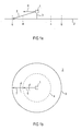
- FIG. 1a and 1b show a device 1 according to the invention, which means of a stand 3 is mounted on a floor area 2.
- the device 1 is surrounded by a protective zone, the outer border is indicated by the dashed line 4.
- the protection zone thus surrounds the device 1 in an angular range of 360 °.
- a first light beam 6 is parallel to the floor 2 sent. Furthermore, the device 1 emits another light beam 7, which is inclined downwards in the manner on the floor 2 is directed that he outside the protection zone boundary 4 on the Floor 2 hits.
- Both light beams 6, 7 are by means of an existing in the device 1 Deflection unit over an angular range of 360 ° in the direction of the arrow (Fig. 1b) distracted. This deflection causes the first beam of light 6 would detect all objects located at the level of the device 1 are within the protection zone boundary 4. Furthermore, the called deflection that the second light beam 7 along a line 5th hits the floor 2, this line 5 being completely outside the protection zone boundary 4 extends.
- the first light beam 6 is always in when the object-free protection zone is present directs and delivers the infinite - there are no objects in the protection zone are present - only distance values, the distances between the device 1 and arranged outside the protection zone 4 Represent objects. Based on these distance values, there is no Warning signal delivery, since these distance values clearly show that within the Protection zone no object is present.
- the second light beam 7 is constantly from the floor 2 along the line 5 to Device 1 reflects back / remitted, so that distance values are permanent here be determined the distance between the device 1 and line 5. The existence of these distance values confirms that the device is working properly. If these distance values with previously saved target distance values (reference background contour) can also be compared be when the device 1 or the environment misaligned or manipulated become. In this case, an error signal can then be output become. However, as long as those determined by means of the second light beam 7 Distance values with the stored distance values at least within predetermined limits, will function correctly of device 1 signals.
- a "protection zone free" signal is always issued when the first light beam 6 only delivers distance values that indicate objects can be outside of protection zone 4 and if that second light signal 7 permanently delivers distance values that a stored Correspond to the background reference contour.
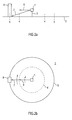
- FIGS. 2a, 2b corresponds essentially to that Arrangement according to FIGS. 1a, 1b with the difference that the second Beam 7 not over the entire angular range of 360 ° to the Floor 2 hits, but in a comparatively small angular range is reflected / remitted by an object 8 which is outside the protection zone boundary 4. Acting on item 8 it is a stationary object which is relative to the device 1 does not make any movements.
- the arrangement works 2a and b corresponding to the arrangement according to 1a and b.
- both light beams 6, 7 deliver Distance values, the distance between the device 1 and the corresponding reflection / remission points on the item 9 represent. Since the distance determined by means of the light beam 6 is smaller is than the distance of the device 1 from the protection zone boundary 4, a warning signal is triggered that the within the Protection zone boundary 4 indicates existing object 9. Since already by means of a distance of the first light beam 6 is determined, which is the Triggering a warning signal is that by means of the second Light beam 7 determined distance value, which of course not in this case represents the distance of the reflection line 5 from the device 1, irrelevant.
- FIGS. 3a, b shows an arrangement which corresponds essentially to FIGS. 3a, b, with the only difference that the within the protection zone boundary 4 existing item 10 not vertically up to Floor 2 extends. Rather, the object 10 is arranged so that it is detected by the first light beam 6, while the second light beam 7 runs under the object 10 and - as with object-free protection zone - is reflected by the reflection line 5 located on the floor 2.
- the means is, however the distance of the second light beam 7 is irrelevant, provided that first light beam 6 provides a distance value that is within an Protected zone boundary 4 indicates object 10. insofar a warning signal is also given in the arrangement according to FIGS. 4a, b.
Landscapes
- Physics & Mathematics (AREA)
- Electromagnetism (AREA)
- Engineering & Computer Science (AREA)
- Computer Networks & Wireless Communication (AREA)
- General Physics & Mathematics (AREA)
- Radar, Positioning & Navigation (AREA)
- Remote Sensing (AREA)
- Optical Radar Systems And Details Thereof (AREA)
- Burglar Alarm Systems (AREA)
- Geophysics And Detection Of Objects (AREA)
Abstract
Description
daß zumindest zwei, einen Winkel zwischen sich einschließende Lichtstrahlen ausgesandt werden,
daß bei innerhalb der Schutzzone vorhandenem Objekt ein erster, von dem Objekt reflektierter/remittierter Lichtstrahl empfangen wird,
daß bei objektfreier Schutzzone ein zweiter, von einem außerhalb der Schutzzone befindlichen Ort reflektierter/remittierter Lichtstrahl empfangen wird, und
daß der Abstand sowohl des Objekts als auch des zweiten Orts von der Vorrichtung bestimmt wird.
daß die Sendeeinheit zur Aussendung von zumindest zwei, einen Winkel zwischen sich einschließenden Lichtstrahlen ausgelegt ist,
daß die Empfangseinheit zum Empfang eines ersten, von einem innerhalb der Schutzzone befindlichen Objekt und eines zweiten, von einem außerhalb der Schutzzone befindlichen Ort reflektierten/remittierten Lichtstrahls ausgelegt ist, und
daß die Auswerteeinheit zur Bestimmung des Abstandes sowohl des Objekts als auch des außerhalb der Schutzzone liegenden Orts von der Vorrichtung ausgelegt ist.
Zudem wird es in bestimmten Fällen möglich, den Abstand eines innerhalb der Schutzzone befindlichen Objekts von der Vorrichtung durch beide Lichtstrahlen in redundanter Weise - und somit mit erhöhter Sicherheit - zu ermitteln, wobei eine gültige Messung nur dann vorliegt, wenn über beide Lichtstrahlen zumindest im wesentlichen das gleiche Abstandsergebnis erzielt wird.
daß die Sendeeinheit zur Aussendung von zumindest zwei, einen Winkel zwischen sich einschließenden Lichtstrahlen ausgelegt ist,
daß die Empfangseinheit zum Empfang eines ersten, von einem innerhalb der Schutzzone befindlichen Objekt und eines zweiten, von einem außerhalb der Schutzzone befindlichen Ort reflektierten/remittierten Lichtstrahls ausgelegt ist, und
daß die Auswerteeinheit zur Bestimmung des Abstandes sowohl des Objekts als auch des außerhalb der Schutzzone liegenden Orts von der Vorrichtung ausgelegt ist.
- Fig. 1a
- eine schematisierte Seitenansicht einer Anordnung zur Durchführung des erfindungsgemäßen Verfahrens,
- Fig. 1b
- eine Draufsicht auf die Anordnung gemäß Fig. 1a,
- Fig. 2a
- eine Seitenansicht gemäß Fig. 1a mit einem im Hintergrund befindlichen Gegenstand,
- Fig. 2b
- eine Draufsicht auf eine Anordnung gemäß Fig. 2a,
- Fig. 3a
- eine Seitenansicht gemäß Fig. 1a mit einem ersten in der Schutzzone befindlichen Gegenstand,
- Fig. 3b
- eine Draufsicht auf die Anordnung gemäß Fig. 3a,
- Fig. 4a
- eine Seitenansicht gemäß Fig. 1a mit einem zweiten in der Schutzzone befindlichen Gegenstand, und
- Fig. 4b
- eine Draufsicht auf eine Anordnung gemäß Fig. 4a.
- 1
- Vorrichtung
- 2
- Boden
- 3
- Ständer
- 4
- Schutzzonenbegrenzung
- 5
- Reflexionslinie
- 6
- erster Lichtstrahl
- 7
- zweiter Lichtstrahl
- 8
- Gegenstand
- 9
- Objekt
- 10
- Objekt
Claims (23)
- Verfahren zur Überwachung einer Schutzzone (4), bei dem von einer Vorrichtung (1) ein Lichtstrahl (6) in Richtung der Schutzzone (4) ausgesandt, ein von einem in der Schutzzone (4) befindlichen Objekt (9, 10) reflektierter/remittierter Lichtstrahl (6) empfangen und der Abstand zwischen der Vorrichtung (1) und dem Objekt (9, 10) bestimmt wird,
dadurch gekennzeichnet, daß zumindest zwei, einen Winkel zwischen sich einschließende Lichtstrahlen (6, 7) ausgesandt werden,
daß bei innerhalb der Schutzzone (4) vorhandenem Objekt (9, 10) ein erster, von dem Objekt (9, 10) reflektierter/remittierter Lichtstrahl (6) empfangen wird,
daß bei objektfreier Schutzzone (4) ein zweiter, von einem außerhalb der Schutzzone (4) befindlichen Ort (5) reflektierter/remittierter Lichtstrahl (7) empfangen wird, und
daß der Abstand sowohl des Objekts (9, 10) als auch des zweiten Orts (5) von der Vorrichtung (1) bestimmt wird. - Verfahren nach Anspruch 1,
dadurch gekennzeichnet, daß die ausgesandten Lichtstrahlen (6, 7) zum periodischen Abtasten der Schutzzone (4) innerhalb einer Ebene, welche sich zumindest im wesentlichen senkrecht zu der von den ausgesandten Lichtstrahlen (6, 7) aufgespannten Ebene erstreckt, abgelenkt werden, wobei insbesondere die jeweiligen Ablenkwinkel der ausgesandten Lichtstrahlen (6, 7) erfaßt werden und/oder aus den Abstandswerten und den zugehörigen Ablenkwinkeln die Positionen bestimmt werden, von den die Lichtstrahlen (6, 7) reflektiert/remittiert werden. - Verfahren nach einem der vorhergehenden Ansprüche,
dadurch gekennzeichnet, daß die ermittelten Abstandswerte mit zuvor gespeicherten Abstandswerten oder aus den Abstands- und Ablenkwinkelwerten ermittelte Positionen mit zuvor gespeicherten Positionen verglichen werden, wobei insbesondere ein Warn- oder Fehlersignal erzeugt wird, wenn zwischen den ermittelten Abstandswerten und den zuvor gespeicherten Abstandswerten oder zwischen den ermittelten Positionen und den zuvor gespeicherten Positionen zumindest eine vorgegebene Abweichung auftritt. - Verfahren nach einem der vorhergehenden Ansprüche,
dadurch gekennzeichnet, daß die Positionen der Schutzzonenbegrenzung (4) gespeichert werden. - Verfahren nach einem der vorhergehenden Ansprüche,
dadurch gekennzeichnet, daß der zweite ausgesandte Lichtstrahl (7) zumindest in einem ersten Ablenkwinkelbereich auf den Boden (2) oder die Decke eines die Schutzzone (4) umgebenden Bereichs gerichtet wird, wobei insbesondere der zweite ausgesandte Lichtstrahl (7) in einem zweiten Ablenkwinkelbereich auf außerhalb der Schutzzone (4) befindliche Gegenstände (8), wie z.B. Wände oder stationäre Maschinen gerichtet wird. - Verfahren nach einem der vorhergehenden Ansprüche,
dadurch gekennzeichnet, daß eine Referenzkontur ermittelt wird, indem der zweite Lichtstrahl (7) den Boden (2) oder die Decke eines die Schutzzone (4) umgebenden Bereichs und/oder außerhalb der Schutzzone befindliche Gegenstände (8) abtastet und jeweils derjenige Ort ermittelt wird, an dem der zweite Lichtstrahl (7) reflektiert/remittiert wird. - Verfahren nach einem der vorhergehenden Ansprüche,
dadurch gekennzeichnet, daß der erste ausgesandte Lichtstrahl (6) parallel oder geneigt zum Boden (2) der Schutzzone (9) verläuft, so daß alle innerhalb der Schutzzone (4) befindlichen Objekte (9, 10) vom ersten Lichtstrahl (6) erfaßbar sind. - Verfahren nach einem der vorhergehenden Ansprüche,
dadurch gekennzeichnet, daß ein Signal "Schutzzone nicht frei" bereits dann generiert wird, wenn der erste ausgesandte Lichtstrahl (6) innerhalb der Schutzzone (4) ein unzulässiges Objekt (9, 10) detektiert, und/oder daß ein Signal "Schutzzone frei" generiert wird, wenn mittels des zweiten Lichtstrahls (7) der Boden (2) oder die Decke eines die Schutzzone (4) umgebenden Bereichs detektiert und zugleich der erste ausgesandte Lichtstrahl (6) nicht von einem innerhalb der Schutzzone (4) befindlichen unzulässigen Objekt (9, 10) reflektiert/remittiert wird. - Verfahren nach einem der Ansprüche 6 bis 8,
dadurch gekennzeichnet, daß ein "Schutzzone frei"-Signal generiert wird, wenn die mittels des zweiten Lichtstrahls (7) ermittelte Kontur (5) nicht oder nur innerhalb von vorgegebenen Schwellwerten von der Referenzkontur abweicht und zugleich der erste ausgesandte Lichtstrahl (6) nicht von einem innerhalb der Schutzzone (4) befindlichen unzulässigen Objekt (9, 10) reflektiert/remittiert wird. - Verfahren nach einem der Ansprüche 6 bis 9,
dadurch gekennzeichnet, daß mittels des zweiten Lichtstrahls (7) in bestimmten Zeitabständen die jeweils aktuelle Kontur (5) ermittelt und mit der gespeicherten Referenzkontur verglichen wird, wobei ein Dejustage- oder Manipulationssignal erzeugt wird, wenn die aktuelle Kontur (5) zumindest in einem vorgegebenen Maß von der Referenzkontur abweicht. - Verfahren nach einem der vorhergehenden Ansprüche,
dadurch gekennzeichnet, daß zumindest ein weiterer ausgesandter Lichtstrahl zumindest in einem ersten Ablenkwinkelbereich auf den Boden (2) oder die Decke eines die Schutzzone (4) umgebenden Bereichs gerichtet wird und insbesondere
daß der weitere ausgesandte Lichtstrahl in einem zweiten Ablenkwinkelbereich auf außerhalb der Schutzzone befindliche Gegenstände (8), wie z.B. Wände oder stationäre Maschinen gerichtet wird. - Verfahren nach einem der vorhergehenden Ansprüche,
dadurch gekennzeichnet, daß zumindest ein weiterer ausgesandter Lichtstrahl parallel oder geneigt zum Boden (2) der Schutzzone (4) verläuft, so daß alle innerhalb der Schutzzone (4) befindlichen Objekte (9, 10) von diesem weiteren Lichtstrahl erfaßbar sind. - Verfahren nach einem der vorhergehenden Ansprüche,
dadurch gekennzeichnet, daß die Lichtstrahlen (6, 7) in Form von Lichtimpulsen erzeugt und die Abstandswerte über die jeweilige Lichtlaufzeit oder über eine Triangulationsmessung ermittelt werden. - Verfahren nach einem der vorhergehenden Ansprüche,
dadurch gekennzeichnet, daß der Abstand zwischen der Vorrichtung (1) und einem innerhalb der Schutzzone (4) befindlichen Objekt (9, 10) in redundanter Weise über zumindest zwei ausgesandte Lichtstrahlen bestimmt wird und ein "Schutzzone frei"-Signal nur dann generiert werden kann, wenn sich die ermittelten Abstandswerte nicht oder nur innerhalb einer vorgegebenen Toleranz voneinander unterscheiden. - Verfahren nach einem der vorhergehenden Ansprüche,
dadurch gekennzeichnet, daß alle ausgesandten Lichtstrahlen (6, 7) über ein reflektierendes/remittierendes, bevorzugt innerhalb der Vorrichtung angeordnetes Referenzziel geführt werden, wobei insbesondere der Abstand zum Referenzziel in redundanter Weise über zumindest zwei ausgesandte Lichtstrahlen bestimmt wird und ein Signal "Schutzzone frei" nur dann generiert werden kann, wenn sich die ermittelten Abstandswerte nicht oder nur innerhalb einer vorgegebenen Toleranz voneinander unterscheiden. - Vorrichtung zur Überwachung einer Schutzzone (4) mit einer Sendeeinheit zur Aussendung eines Lichtstrahls (6) in Richtung der Schutzzone(4) , einer Empfangseinheit zum Empfang eines von einem in der Schutzzone (4) befindlichen Objekt (9, 10) reflektierten/remittierten Lichtstrahls und einer Auswerteeinheit zur Bestimmung des Abstandes zwischen der Vorrichtung (1) und dem Objekt (9, 10),
dadurch gekennzeichnet, daß die Sendeeinheit zur Aussendung von zumindest zwei, einen Winkel zwischen sich einschließenden Lichtstrahlen (6, 7) ausgelegt ist,
daß die Empfangseinheit zum Empfang eines ersten, von einem innerhalb der Schutzzone befindlichen Objekt (9, 10) und eines zweiten, von einem außerhalb der Schutzzone (4) befindlichen Ort (5) reflektierten/remittierten Lichtstrahls (6, 7) ausgelegt ist, und
daß die Auswerteeinheit zur Bestimmung des Abstandes sowohl des Objekts (9, 10) als auch des außerhalb der Schutzzone liegenden Orts (5) von der Vorrichtung (1) ausgelegt ist. - Vorrichtung nach Anspruch 16,
gekennzeichnet durch
eine Lichtablenkeinheit, insbesondere einen Prismenkopf zur Ablenkung der ausgesandten Lichtstrahlen (6, 7) innerhalb einer Ebene, welche sich zumindest im wesentlichen senkrecht zu der von den ausgesandten Lichtstrahlen (6, 7) aufgespannten Ebene erstreckt. - Vorrichtung nach einem der Ansprüche 16 oder 17, gekennzeichnet durch
eine Winkelerfassungseinheit zur Ermittlung des jeweiligen Ablenkwinkels der ausgesandten Lichtstrahlen (6, 7). - Vorrichtung nach einem der Ansprüche 16 bis 18,
dadurch gekennzeichnet, daß die Sendeeinheit einen einzigen Lichtsender zur Erzeugung zumindest des ersten und zweiten Lichtstrahls (6, 7) mittels eines Strahlenfächers umfasst, oder daß die Sendeeinheit zumindest zwei Lichtsender zur gleichzeitig oder im Zeitmultiplex erfolgenden Erzeugung zumindest des ersten und zweiten Lichtstrahls (6, 7) umfaßt. - Vorrichtung nach einem der Ansprüche 16 bis 19,
dadurch gekennzeichnet, daß die Empfangseinheit nur einen einzelnen Lichtempfänger zum im Zeitmultiplex erfolgenden Empfang zumindest des ersten und des zweiten Lichtstrahls (6, 7) umfasst, oder daß die Empfangseinheit als Doppel- oder Mehrfachempfänger ausgebildet ist. - Vorrichtung nach einem der Ansprüche 16 bis 20, gekennzeichnet durch
einen zusätzlichen Empfänger zum Empfang eines von der Sendeeinheit ausgesandten und innerhalb der Vorrichtung zum zusätzlichen Empfänger geleiteten Lichtsignals. - Vorrichtung nach einem der Ansprüche 16 bis 21, gekennzeichnet durch
ein reflektierendes oder remittierendes, bevorzugt innerhalb der Vorrichtung angeordnetes Referenzziel, welches von allen ausgesandten Lichtstrahlen (6, 7) erfaßt wird. - Vorrichtung nach einem der Ansprüche 16 bis 22, gekennzeichnet durch
eine Vergleichseinheit zum Vergleich der ermittelten Abstandswerte mit zuvor gespeicherten Abstandswerten oder zum Vergleich von aus den Abstands- und Ablenkwinkelwerten ermittelten Positionen mit zuvor gespeicherten Positionen.
Applications Claiming Priority (2)
| Application Number | Priority Date | Filing Date | Title |
|---|---|---|---|
| DE10110416A DE10110416A1 (de) | 2001-03-05 | 2001-03-05 | Verfahren und Vorrichtung zur Überwachung einer Schutzzone |
| DE10110416 | 2001-03-05 |
Publications (1)
| Publication Number | Publication Date |
|---|---|
| EP1239301A1 true EP1239301A1 (de) | 2002-09-11 |
Family
ID=7676288
Family Applications (1)
| Application Number | Title | Priority Date | Filing Date |
|---|---|---|---|
| EP02004866A Withdrawn EP1239301A1 (de) | 2001-03-05 | 2002-03-04 | Verfahren und Vorrichtung zur Überwachung einer Schutzzone |
Country Status (4)
| Country | Link |
|---|---|
| US (1) | US6812450B2 (de) |
| EP (1) | EP1239301A1 (de) |
| JP (1) | JP2002341033A (de) |
| DE (1) | DE10110416A1 (de) |
Cited By (6)
| Publication number | Priority date | Publication date | Assignee | Title |
|---|---|---|---|---|
| FR2888945A1 (fr) * | 2005-07-22 | 2007-01-26 | Johnson Controls Tech Co | Dispositif de detection au moyen de faisceaux croises du franchissement d'une ligne delimitant une voie de circulation sur une surface |
| EP1883786A4 (de) * | 2005-05-26 | 2010-06-02 | Bae Systems Information | Bordlichtquelle auf basis einer verstärkungskorrektur für halbaktive lasersucher |
| EP2306217A1 (de) | 2009-09-30 | 2011-04-06 | Sick Ag | Umgebungserfassung |
| US8873058B2 (en) | 2012-02-24 | 2014-10-28 | Sick Ag | Optical sensor |
| US9001330B2 (en) | 2012-03-07 | 2015-04-07 | Sick Ag | Attachment for placement onto an optical sensor and method of operating an optical sensor |
| US9140820B2 (en) | 2012-02-24 | 2015-09-22 | Sick Ag | Optical sensor and test method for testing the operability of an optical sensor |
Families Citing this family (23)
| Publication number | Priority date | Publication date | Assignee | Title |
|---|---|---|---|---|
| US6950021B2 (en) * | 2003-09-23 | 2005-09-27 | Walker Butler | Electronic wall using high-resolution millimeter-wave radar in conjunction with multiple plane reflectors and retroreflectors |
| DE102004044973B4 (de) * | 2004-09-16 | 2014-12-04 | Sick Ag | Kontrolle eines Überwachungsbereiches |
| USRE46672E1 (en) | 2006-07-13 | 2018-01-16 | Velodyne Lidar, Inc. | High definition LiDAR system |
| JP5377837B2 (ja) | 2007-05-31 | 2013-12-25 | 株式会社キーエンス | 光電センサ |
| JP5523236B2 (ja) * | 2010-07-27 | 2014-06-18 | セコム株式会社 | 監視用センサ |
| JP5539092B2 (ja) * | 2010-07-29 | 2014-07-02 | セコム株式会社 | 監視用センサ |
| JP5781174B2 (ja) * | 2014-02-17 | 2015-09-16 | セコム株式会社 | 監視用センサ |
| JP6530251B2 (ja) * | 2015-06-17 | 2019-06-12 | 株式会社デンソーウェーブ | エリア監視システム |
| US10627490B2 (en) | 2016-01-31 | 2020-04-21 | Velodyne Lidar, Inc. | Multiple pulse, LIDAR based 3-D imaging |
| CA3017735C (en) | 2016-03-19 | 2023-03-14 | Velodyne Lidar, Inc. | Integrated illumination and detection for lidar based 3-d imaging |
| WO2017210418A1 (en) | 2016-06-01 | 2017-12-07 | Velodyne Lidar, Inc. | Multiple pixel scanning lidar |
| KR20180064951A (ko) * | 2016-12-06 | 2018-06-15 | 주식회사 비트센싱 | 레이더와 반사체를 이용한 직선의 가상펜스 시스템 |
| JP7290571B2 (ja) | 2017-03-31 | 2023-06-13 | ベロダイン ライダー ユーエスエー,インコーポレイテッド | 統合化されたlidar照明出力制御 |
| JP2020519881A (ja) | 2017-05-08 | 2020-07-02 | ベロダイン ライダー, インク. | Lidarデータ収集及び制御 |
| US11294041B2 (en) * | 2017-12-08 | 2022-04-05 | Velodyne Lidar Usa, Inc. | Systems and methods for improving detection of a return signal in a light ranging and detection system |
| EP3572971B1 (de) * | 2018-05-22 | 2021-02-24 | Sick Ag | Absichern eines überwachungsbereichs mit mindestens einer maschine |
| US11971507B2 (en) | 2018-08-24 | 2024-04-30 | Velodyne Lidar Usa, Inc. | Systems and methods for mitigating optical crosstalk in a light ranging and detection system |
| US10712434B2 (en) | 2018-09-18 | 2020-07-14 | Velodyne Lidar, Inc. | Multi-channel LIDAR illumination driver |
| US11082010B2 (en) | 2018-11-06 | 2021-08-03 | Velodyne Lidar Usa, Inc. | Systems and methods for TIA base current detection and compensation |
| US12061263B2 (en) | 2019-01-07 | 2024-08-13 | Velodyne Lidar Usa, Inc. | Systems and methods for a configurable sensor system |
| US11885958B2 (en) | 2019-01-07 | 2024-01-30 | Velodyne Lidar Usa, Inc. | Systems and methods for a dual axis resonant scanning mirror |
| US10613203B1 (en) | 2019-07-01 | 2020-04-07 | Velodyne Lidar, Inc. | Interference mitigation for light detection and ranging |
| DE102023110100A1 (de) | 2023-04-20 | 2024-10-24 | Sick Ag | System zur Überwachung eines Bahnübergangs |
Citations (4)
| Publication number | Priority date | Publication date | Assignee | Title |
|---|---|---|---|---|
| US4225226A (en) * | 1978-12-29 | 1980-09-30 | Spectra-Physics, Inc. | Laser guidance system for crop spraying aircraft |
| US4967183A (en) * | 1988-05-18 | 1990-10-30 | Eastman Kodak Company | Method of intrusion detection over a wide area |
| EP0396822A1 (de) * | 1989-04-18 | 1990-11-14 | Rheinmetall GmbH | Abstandsmine mit optischem Suchzünder |
| WO1999028696A1 (de) * | 1997-11-27 | 1999-06-10 | Dynamit Nobel Gmbh Explosivstoff- Und Systemtechnik | Verfahren zur einstellung einer automatischen waffe zur bekämpfung von fahrzeugen |
Family Cites Families (11)
| Publication number | Priority date | Publication date | Assignee | Title |
|---|---|---|---|---|
| US3727207A (en) * | 1970-06-24 | 1973-04-10 | Systron Donner Corp | Intrusion detector |
| GB2158232B (en) * | 1984-04-25 | 1987-11-18 | Matsushita Electric Works Ltd | Object detecting apparatus including photosensors for restricted detection area |
| US4903009A (en) * | 1988-05-18 | 1990-02-20 | Eastman Kodak Company | Intrusion detection device |
| CH681756A5 (de) * | 1990-11-12 | 1993-05-14 | Beat Decoi | |
| US5612781A (en) * | 1993-09-09 | 1997-03-18 | Kabushiki Kaisha Topcon | Object reflector detection system |
| US5414255A (en) * | 1993-11-08 | 1995-05-09 | Scantronic Limited | Intrusion detector having a generally planar fresnel lens provided on a planar mirror surface |
| DE4411448C5 (de) * | 1994-03-31 | 2009-05-14 | Sick Ag | Verfahren und Vorrichtung zur Kontrolle eines vorgegebenen Überwachungsbereichs |
| US5508511A (en) * | 1994-05-24 | 1996-04-16 | Interactive Light, Inc. | Arrangement for and method of detecting an object in an area subject to environmental variations |
| DE4424537A1 (de) * | 1994-07-12 | 1996-01-18 | Sick Optik Elektronik Erwin | Verfahren zum Betrieb eines Lichtgitters und Lichtgitter |
| DE19828000C2 (de) * | 1998-06-24 | 2000-06-21 | Schmersal Eot Gmbh & Co Kg | Verfahren zur optoelektronischen Überwachung eines Schutzbereichs |
| US6466157B1 (en) * | 2001-07-17 | 2002-10-15 | Sensor Technologies & Systems, Inc. | Electronic fence using high-resolution millimeter-wave radar in conjunction with multiple passive reflectors |
-
2001
- 2001-03-05 DE DE10110416A patent/DE10110416A1/de not_active Ceased
-
2002
- 2002-03-04 EP EP02004866A patent/EP1239301A1/de not_active Withdrawn
- 2002-03-05 US US10/093,087 patent/US6812450B2/en not_active Expired - Lifetime
- 2002-03-05 JP JP2002059069A patent/JP2002341033A/ja active Pending
Patent Citations (4)
| Publication number | Priority date | Publication date | Assignee | Title |
|---|---|---|---|---|
| US4225226A (en) * | 1978-12-29 | 1980-09-30 | Spectra-Physics, Inc. | Laser guidance system for crop spraying aircraft |
| US4967183A (en) * | 1988-05-18 | 1990-10-30 | Eastman Kodak Company | Method of intrusion detection over a wide area |
| EP0396822A1 (de) * | 1989-04-18 | 1990-11-14 | Rheinmetall GmbH | Abstandsmine mit optischem Suchzünder |
| WO1999028696A1 (de) * | 1997-11-27 | 1999-06-10 | Dynamit Nobel Gmbh Explosivstoff- Und Systemtechnik | Verfahren zur einstellung einer automatischen waffe zur bekämpfung von fahrzeugen |
Cited By (8)
| Publication number | Priority date | Publication date | Assignee | Title |
|---|---|---|---|---|
| EP1883786A4 (de) * | 2005-05-26 | 2010-06-02 | Bae Systems Information | Bordlichtquelle auf basis einer verstärkungskorrektur für halbaktive lasersucher |
| FR2888945A1 (fr) * | 2005-07-22 | 2007-01-26 | Johnson Controls Tech Co | Dispositif de detection au moyen de faisceaux croises du franchissement d'une ligne delimitant une voie de circulation sur une surface |
| WO2007009815A3 (fr) * | 2005-07-22 | 2007-04-26 | Johnson Controls Tech Co | Dispositif de detection au moyen de faisceaux croises du franchissement d’une ligne delimitant une voie de circulation sur une surface |
| EP2306217A1 (de) | 2009-09-30 | 2011-04-06 | Sick Ag | Umgebungserfassung |
| US8873058B2 (en) | 2012-02-24 | 2014-10-28 | Sick Ag | Optical sensor |
| US9140820B2 (en) | 2012-02-24 | 2015-09-22 | Sick Ag | Optical sensor and test method for testing the operability of an optical sensor |
| US9001330B2 (en) | 2012-03-07 | 2015-04-07 | Sick Ag | Attachment for placement onto an optical sensor and method of operating an optical sensor |
| US9354169B2 (en) | 2012-03-07 | 2016-05-31 | Sick Ag | Attachment for placement onto an optical sensor and method of operating an optical sensor |
Also Published As
| Publication number | Publication date |
|---|---|
| US20030168581A1 (en) | 2003-09-11 |
| US6812450B2 (en) | 2004-11-02 |
| DE10110416A1 (de) | 2002-09-12 |
| JP2002341033A (ja) | 2002-11-27 |
Similar Documents
| Publication | Publication Date | Title |
|---|---|---|
| DE10110416A1 (de) | Verfahren und Vorrichtung zur Überwachung einer Schutzzone | |
| EP1548351B1 (de) | Vorrichtung zur Überwachung eines Erfassungsbereichs an einem Arbeitsmittel | |
| EP1089030B1 (de) | Verfahren und Vorrichtung zum Überwachen eines Schutzbereichs | |
| EP1993081B1 (de) | Optoelektronische Sensoranordnung und Verfahren zur Überwachung eines Überwachungsbereiches | |
| EP1494048B1 (de) | Lichtgitter | |
| EP1544643B1 (de) | Verfahren und Vorrichtung zur Flächenüberwachung mit mehreren nebeneinander angeordneten Lichtsendern | |
| EP2017524B1 (de) | Lichtgitter | |
| EP3435117B1 (de) | Sensor und verfahren zur erfassung und abstandsbestimmung von objekten | |
| EP3910230B1 (de) | Überwachungseinrichtung | |
| EP3885635B1 (de) | Überwachungseinrichtung zur absicherung des zugangs zu einem gefahrenbereich mit einem sicherheitssensor | |
| DE3932665A1 (de) | Ueberwachungsvorrichtung | |
| EP3588139A1 (de) | Optoelektronischer sensor und verfahren zur abstandsbestimmung | |
| EP0875873B2 (de) | Opto-elektronischer Sensor | |
| DE102005030829A1 (de) | Verfahren zum Betrieb eines Lichtgitters und Lichtgitter | |
| DE102019110803B3 (de) | Sicherheitslaserscanner zur Erfassung von Objekten in einem Überwachungsbereich | |
| EP0280137B1 (de) | Sicherheitsvorrichtung für System mit fahrerlosen Fahrzeugen | |
| DE102022133248B4 (de) | System mit einem Sensor und Verfahren mit einem Sensor zur Überwachung mehrerer Schutzbereiche | |
| WO2021069119A1 (de) | Sicherheitsvorrichtung zur sicherung einer gefahrenstelle, verfahren zur steuerung einer sicherheitsvorrichtung, computerprogrammprodukt und computerlesbares aufzeichnungsmedium | |
| EP4306998A1 (de) | Optischer sensor | |
| EP2584375B1 (de) | Türüberwachungssensor und Verfahren zum Überwachen der Gegenschliesskante einer Tür, insbesondere einer Karusseltür | |
| EP4524608B1 (de) | Sensor zum überwachen eines bereichs | |
| EP3910228A1 (de) | Überwachungseinrichtung und ein verfahren zum betrieb einer überwachungseinrichtung | |
| EP3851729B1 (de) | Optischer sensor und ein verfahren zur erfassung von objekten mittels eines optischen sensors | |
| EP3872526B1 (de) | Vorrichtung zum überwachen eines schutzbereichs | |
| EP3910229B1 (de) | Überwachungseinrichtung |
Legal Events
| Date | Code | Title | Description |
|---|---|---|---|
| PUAI | Public reference made under article 153(3) epc to a published international application that has entered the european phase |
Free format text: ORIGINAL CODE: 0009012 |
|
| AK | Designated contracting states |
Kind code of ref document: A1 Designated state(s): AT BE CH CY DE DK ES FI FR GB GR IE IT LI LU MC NL PT SE TR |
|
| AX | Request for extension of the european patent |
Free format text: AL;LT;LV;MK;RO;SI |
|
| AKX | Designation fees paid | ||
| 17P | Request for examination filed |
Effective date: 20021028 |
|
| RBV | Designated contracting states (corrected) |
Designated state(s): AT BE CH CY DE DK ES FI FR GB GR IE IT LI LU MC NL PT SE TR |
|
| REG | Reference to a national code |
Ref country code: DE Ref legal event code: 8566 |
|
| 17Q | First examination report despatched |
Effective date: 20041222 |
|
| RAP1 | Party data changed (applicant data changed or rights of an application transferred) |
Owner name: SICK AG |
|
| STAA | Information on the status of an ep patent application or granted ep patent |
Free format text: STATUS: THE APPLICATION IS DEEMED TO BE WITHDRAWN |
|
| 18D | Application deemed to be withdrawn |
Effective date: 20080104 |