EP1239178A2 - Reverse input blocking clutch - Google Patents
Reverse input blocking clutch Download PDFInfo
- Publication number
- EP1239178A2 EP1239178A2 EP02251610A EP02251610A EP1239178A2 EP 1239178 A2 EP1239178 A2 EP 1239178A2 EP 02251610 A EP02251610 A EP 02251610A EP 02251610 A EP02251610 A EP 02251610A EP 1239178 A2 EP1239178 A2 EP 1239178A2
- Authority
- EP
- European Patent Office
- Prior art keywords
- input
- output
- torque
- section
- engagement
- Prior art date
- Legal status (The legal status is an assumption and is not a legal conclusion. Google has not performed a legal analysis and makes no representation as to the accuracy of the status listed.)
- Granted
Links
- 230000002441 reversible effect Effects 0.000 title claims abstract description 171
- 230000000903 blocking effect Effects 0.000 title claims abstract description 93
- 230000005540 biological transmission Effects 0.000 claims abstract description 61
- 239000002184 metal Substances 0.000 claims abstract description 13
- 230000007246 mechanism Effects 0.000 claims description 37
- 230000000452 restraining effect Effects 0.000 claims description 18
- 210000002105 tongue Anatomy 0.000 claims description 17
- 230000007935 neutral effect Effects 0.000 claims description 9
- 238000003825 pressing Methods 0.000 claims description 4
- 229910000831 Steel Inorganic materials 0.000 abstract description 4
- 239000010959 steel Substances 0.000 abstract description 4
- 230000009467 reduction Effects 0.000 description 28
- 238000010276 construction Methods 0.000 description 25
- 238000003860 storage Methods 0.000 description 8
- 230000009471 action Effects 0.000 description 4
- 238000006073 displacement reaction Methods 0.000 description 4
- 230000002829 reductive effect Effects 0.000 description 4
- 230000000717 retained effect Effects 0.000 description 4
- 230000005489 elastic deformation Effects 0.000 description 3
- 238000004519 manufacturing process Methods 0.000 description 3
- 238000000034 method Methods 0.000 description 3
- 229910000760 Hardened steel Inorganic materials 0.000 description 2
- 210000000078 claw Anatomy 0.000 description 2
- 230000002939 deleterious effect Effects 0.000 description 2
- 238000001514 detection method Methods 0.000 description 2
- 230000000694 effects Effects 0.000 description 2
- 239000012530 fluid Substances 0.000 description 2
- 238000003384 imaging method Methods 0.000 description 2
- 238000007689 inspection Methods 0.000 description 2
- 239000007769 metal material Substances 0.000 description 2
- 239000011347 resin Substances 0.000 description 2
- 229920005989 resin Polymers 0.000 description 2
- 229910000639 Spring steel Inorganic materials 0.000 description 1
- 238000010521 absorption reaction Methods 0.000 description 1
- 238000005452 bending Methods 0.000 description 1
- 238000006243 chemical reaction Methods 0.000 description 1
- 238000005520 cutting process Methods 0.000 description 1
- 230000007423 decrease Effects 0.000 description 1
- 230000003247 decreasing effect Effects 0.000 description 1
- 239000010419 fine particle Substances 0.000 description 1
- 239000005357 flat glass Substances 0.000 description 1
- 239000004519 grease Substances 0.000 description 1
- 230000006872 improvement Effects 0.000 description 1
- 238000009434 installation Methods 0.000 description 1
- 230000014759 maintenance of location Effects 0.000 description 1
- 239000000463 material Substances 0.000 description 1
- 230000013011 mating Effects 0.000 description 1
- 238000000465 moulding Methods 0.000 description 1
- 230000000474 nursing effect Effects 0.000 description 1
- 230000036961 partial effect Effects 0.000 description 1
- 230000008569 process Effects 0.000 description 1
- 238000005096 rolling process Methods 0.000 description 1
Images







Classifications
-
- F—MECHANICAL ENGINEERING; LIGHTING; HEATING; WEAPONS; BLASTING
- F16—ENGINEERING ELEMENTS AND UNITS; GENERAL MEASURES FOR PRODUCING AND MAINTAINING EFFECTIVE FUNCTIONING OF MACHINES OR INSTALLATIONS; THERMAL INSULATION IN GENERAL
- F16D—COUPLINGS FOR TRANSMITTING ROTATION; CLUTCHES; BRAKES
- F16D41/00—Freewheels or freewheel clutches
- F16D41/06—Freewheels or freewheel clutches with intermediate wedging coupling members between an inner and an outer surface
- F16D41/08—Freewheels or freewheel clutches with intermediate wedging coupling members between an inner and an outer surface with provision for altering the freewheeling action
- F16D41/10—Freewheels or freewheel clutches with intermediate wedging coupling members between an inner and an outer surface with provision for altering the freewheeling action with self-actuated reversing
-
- B—PERFORMING OPERATIONS; TRANSPORTING
- B60—VEHICLES IN GENERAL
- B60R—VEHICLES, VEHICLE FITTINGS, OR VEHICLE PARTS, NOT OTHERWISE PROVIDED FOR
- B60R1/00—Optical viewing arrangements; Real-time viewing arrangements for drivers or passengers using optical image capturing systems, e.g. cameras or video systems specially adapted for use in or on vehicles
- B60R1/02—Rear-view mirror arrangements
- B60R1/06—Rear-view mirror arrangements mounted on vehicle exterior
- B60R1/062—Rear-view mirror arrangements mounted on vehicle exterior with remote control for adjusting position
- B60R1/07—Rear-view mirror arrangements mounted on vehicle exterior with remote control for adjusting position by electrically powered actuators
- B60R1/074—Rear-view mirror arrangements mounted on vehicle exterior with remote control for adjusting position by electrically powered actuators for retracting the mirror arrangements to a non-use position alongside the vehicle
-
- B—PERFORMING OPERATIONS; TRANSPORTING
- B60—VEHICLES IN GENERAL
- B60R—VEHICLES, VEHICLE FITTINGS, OR VEHICLE PARTS, NOT OTHERWISE PROVIDED FOR
- B60R1/00—Optical viewing arrangements; Real-time viewing arrangements for drivers or passengers using optical image capturing systems, e.g. cameras or video systems specially adapted for use in or on vehicles
- B60R1/02—Rear-view mirror arrangements
- B60R1/06—Rear-view mirror arrangements mounted on vehicle exterior
- B60R1/076—Rear-view mirror arrangements mounted on vehicle exterior yieldable to excessive external force and provided with an indexed use position
-
- F—MECHANICAL ENGINEERING; LIGHTING; HEATING; WEAPONS; BLASTING
- F16—ENGINEERING ELEMENTS AND UNITS; GENERAL MEASURES FOR PRODUCING AND MAINTAINING EFFECTIVE FUNCTIONING OF MACHINES OR INSTALLATIONS; THERMAL INSULATION IN GENERAL
- F16D—COUPLINGS FOR TRANSMITTING ROTATION; CLUTCHES; BRAKES
- F16D41/00—Freewheels or freewheel clutches
- F16D41/06—Freewheels or freewheel clutches with intermediate wedging coupling members between an inner and an outer surface
- F16D41/08—Freewheels or freewheel clutches with intermediate wedging coupling members between an inner and an outer surface with provision for altering the freewheeling action
- F16D41/10—Freewheels or freewheel clutches with intermediate wedging coupling members between an inner and an outer surface with provision for altering the freewheeling action with self-actuated reversing
- F16D41/105—Freewheels or freewheel clutches with intermediate wedging coupling members between an inner and an outer surface with provision for altering the freewheeling action with self-actuated reversing the intermediate members being of circular cross-section, of only one size and wedging by rolling movement not having an axial component between inner and outer races, one of which is cylindrical
Definitions
- an example of such an occasion is when a retention function is employed to prevent the position of the output mechanism fluctuating when the driving source is stopped.
- the input torque from the driving motor in either a forward or reverse direction is input to an opening and closing mechanism on the output side, which then performs the operation for either opening or closing the shutter, although if for some reason (such as a power failure or the like) the driving motor is stopped partway through the opening or closing operation, reverse input torque resulting from the descent of the shutter under its own weight is returned to the input side, resulting in the possibility of damage to the input side components. Consequently, a mechanism is required which holds the position of the shutter, and prevents the return of reverse input torque from the shutter to the input side.
- a mechanism which is capable of transmitting input torque from the motor of the input side to the output side, but also capable of locking the output side with respect to reverse input torque from the output side, thereby preventing the return of reverse input torque to the motor or the reduction gear on the input side.
- An object of the present invention is to provide a reverse input blocking clutch which has the functions described above, and yet is compact, lightweight and low cost, as well as a clutch device using such a reverse input blocking clutch.
- the “locking means" described above incorporates a device which applies an antirotation force by means of a wedge engagement force, an engagement between concave and convex surfaces, frictional force, magnetic force, electromagnetic force, fluid pressure, fluid viscosity resistance or a fine particle medium or the like, although from the viewpoints of cost, the simplicity of the structure and the control mechanism, and the smoothness of operation a device which applies an antirotation force by means of a wedge engagement force is preferred. Specifically, a wedge shaped gap is formed between the output member and the stationary member, and an engagement member is then either engaged into, or disengaged from this gap to switch the device between a locked state and a slipping state respectively.
- this type of construction includes structures in which a cam surface for forming the wedge shaped gap is provided on either the output member or the stationary member (and an engagement member with a circular cross section such as a roller or a ball is used), and structures in which a cam surface for forming the wedge shaped gap is provided on the engagement member (and a sprag or the like is used as the engagement member).
- the "metal plate” described above may be any metal plate capable of being shaped by deformation processing to the desired shape and dimensions.
- deformation processing can utilize techniques such as press working.
- the device is more compact, lighter, and cheaper to produce.
- the lock release process provided by the aforementioned lock release means and the torque transmission process provided by the torque transmission means can be carried out consecutively and reliably.
- rotational driving source refers to a device for generating rotational torque, and includes motors, engines, and hand operated members such as handles, as well as combinations of such devices with reduction gears.
- a connector can be provided for connecting an output shaft of the rotational driving source to the input member, and this connector can be positioned inside the clutch.
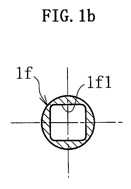
- This connector is preferably provided on a cylindrical section which extends in a continuous manner from the inner perimeter of the input member towards the inside of the clutch, and is also provided with at least one flat surface section which engages with a flat surface on the output shaft of the rotational driving source. This engagement between the flat surface provided on the output shaft of the rotational driving source and the flat surface of the connector causes the output shaft and the input member to be connected in such a manner that prevents relative rotation.
- the reverse input blocking clutch may also comprise a torque transmission member which can be engaged with and disengaged from the input member and the output member in the directions of both forward and reverse rotation, a retainer for retaining the torque transmission member and controlling the engagement and disengagement of the torque transmission member through relative rotation relative to the input member, a first elastic member for connecting the input member and the retainer in a rotational direction, a stationary member, and rotational resistance application means for applying sliding frictional resistance to the retainer for rotation of the retainer relative to the stationary member.
- the above operation can be achieved by forming a wedge shaped gap between the input member and the output member, and then causing an engagement member which functions as the torque transmission member to engage with, or disengage from this wedge shaped gap.
- This type of construction includes structures in which the cam surface for forming the wedge shaped gap is provided on either the output member or the input member (and an engagement member with a circular cross section such as a roller or a ball is used), and structures in which the cam surface for forming the wedge shaped gap is provided on the engagement member (and a sprag or the like is used as the engagement member).
- the driven member could be, for example, a mirror of a vehicle.
- one of the two prescribed positions could be set as a working position in which the mirror protrudes out from the side of the vehicle, and the other position set as a retracted storage position.
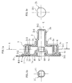
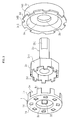
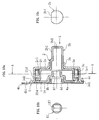
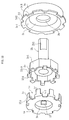
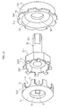
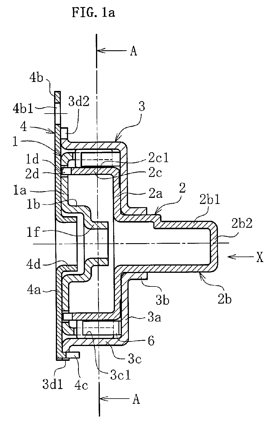
- the input member 1 comprises mainly a flange section 1a which extends in a radial direction, a cylindrical section 1b which extends in a continuous manner in one axial direction (towards the inside of the clutch) from the inner perimeter of the flange section 1a, a plurality (eight for example) of pillars 1c which extend in a continuous manner in one axial direction from the outer perimeter of the flange section 1a, and a plurality (eight for example) of apertures 1d formed in the flange section 1a.
- the output member 2 comprises mainly a flange section 2a which extends in a radial direction, a cylindrical output shaft section 2b which extends in a continuous manner in one axial direction (towards the inside of the clutch) from the inner perimeter of the flange section 2a, a large diameter section 2c which extends from the outer perimeter of the flange section 2a in a continuous manner in the opposite axial direction, and a plurality (eight for example) of protrusions 2d which protrude in an axial direction from one edge of the large diameter section 2c.
- One flat surface 2b1 is provided at the end of the shaft of the output shaft section 2b, and this end of the shaft is connected to a driven member of an output mechanism or a device not shown in the drawings. Then, by engaging the flat section 2b1 at the end of the shaft with a flat section formed on the aforementioned driven member, the output shaft section 2b and the driven member are connected in a manner that prevents relative rotation.
- the end of the shaft and the driven member may also be constructed so that engagement occurs via a plurality of flat surfaces, by either providing two flat surfaces 2b1 180° apart on opposing sides of the end of the shaft, or forming the end of the shaft in a polygonal shape. Furthermore, the end of the shaft of the output shaft section 2b is closed by an end section 2b2.
- the stationary member 3 comprises mainly a flange section 3a which extends in a radial direction, a cylindrical section 3b which extends in a continuous manner in one axial direction from the inner perimeter of the flange section 3a, a large diameter section 3c which extends from the outer perimeter of the flange section 3a in the opposite axial direction, and a collar section 3d extending radially outward from one edge of the large diameter section 3c.
- the large diameter section 3c is provided with an inner surface 3c1 which faces the cam surfaces 2c1 of the output member 2 in a radial direction, forming wedge shaped gaps in the directions of both forward and reverse rotation.
- a plurality (four for example) of rectangular notches 3d1 and a plurality (four for example) of circular arc shaped notches 3d2 are formed with equidistance around the collar section 3d.
- the notches 3d1 match lugs 4c provided on the fixed side plate 4 described below.
- the notches 3d2 are provided to prevent interference with the mounting bolts fitted to brackets 4b of the fixed side plate 4.
- the fixed side plate 4 comprises mainly a flange section 4a which extends in a radial direction, a plurality (four for example) of brackets 4b which extend radially outward from the outer periphery of the flange section 4a, a plurality (four for example) of lugs 4c which extend in one axial direction from the outer periphery of the flange section 4a, and a cylindrical section 4d which extends in a continuous manner in one axial direction (towards the inside of the clutch) from the inner perimeter of the flange section 4a.
- the cylindrical section 4d is inserted inside the cylindrical section 1b of the input member 1, and functions as a bearing (sliding bearing) for supporting the outer surface of an input shaft, not shown in the drawings, in a manner which permits free rotation in a radial direction.
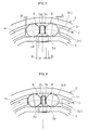
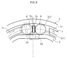
- a pair of rollers 6 which function as engagement members are positioned in each space between the cam surfaces 2c1 of the output member 2 and the inner surface 3c1 of the stationary member 3 (giving a total of eight pairs, for example), and these rollers are housed within the pockets 1e formed between the pillars 1c of the input member 1.
- a tongue 7b of an elastic member 7 described below is positioned between each pair of rollers 6, and pushes the two rollers 6 mutually apart.
- the combination of the cam surfaces 2c1, the inner surface 3c1, the pairs of rollers 6, and the tongues 7b of the elastic member 7 forms the locking means, whereas the lock release means is formed from the pillars 1c (engagement elements) of the input member 1 positioned on both sides of each pair of rollers 6 in a circumferential direction, and the torque transmission means is formed from the apertures 1d of the input member 1 and the protrusions 2d of the output member 2 which are inserted therein.
- Grease or the like may be used to fill the space between the outer surface of the output member 2 and the inner surface of the stationary member 3, particularly the space between the cam surfaces 2c1 and the inner surface 3c1.
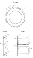
- the outer periphery of the base 7a is a regular octagonal shape, with one pair of tongue sections 7b provided on each side of this octagon.
- Each pair of tongue sections 7b is formed into a curved shape by cutting and lifting a portion of each side of the base 7a, and is connected to the base 7a via a protruding section 7c.
- a pair of tongue sections 7b is sandwiched between a pair of rollers 6, and pushes the two rollers 6 mutually apart in an elastic manner.
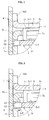
- the pair of rollers 6 are pushed mutually apart by the action of the tongue section 7b of the elastic member 7, and both engage with the wedge shaped gap formed between the cam surface 2c1 and the inner surface 3c1 in the directions of both forward and reverse rotation.
- a gap ⁇ 1 exists in the direction of rotation between each pillar 1c of the input member 1 and each of the rollers 6.
- a gap ⁇ 2 also exists in the directions of both forward and reverse rotation between the protrusion 2d of the output member 2 and the aperture 1d of the input member 1.
- the relationship between the rotational gap ⁇ 1 and the rotational gap ⁇ 2 is such that ⁇ 1 ⁇ ⁇ 2.
- the size of the rotational gap ⁇ 1 is typically from 0 to 0.4 mm (an angle of 0 to 1.5° about the central axis of the clutch), and the size of the rotational gap ⁇ 2 is typically from 0.4 to 0.8 mm (an angle of 1.8 to 3.7° about the central axis of the clutch).
- this roller 6 on the counter clockwise side (the rear roller relative to the rotational direction) disengages from the wedge shaped gap on that side, and the locked state of the output member 2 is released.
- the roller 6 on the clockwise side (the front roller relative to the rotational direction) does not engage with the wedge shaped gap on that side ⁇ . Consequently, the output member 2 is able to rotate in a clockwise direction.
- FIG. 10 to FIG. 12 show a second embodiment of the present invention.
- This second embodiment differs from the first embodiment described above in that the torque transmission means employs an engagement structure comprising notches 21d and protrusions 22d which project radially outward.
- the notches 21d are formed in the outer edge of the flange section 1a of the input member 1.
- a plurality (eight for example) of notches 21d are formed, and these are arranged with equidistance around the periphery of the flange section 1a.
- the base ends 1c1 of the pillars 1c are slightly wider in a circumferential direction than the tips, and the notches 21d are positioned between each set of adjacent base ends 1c1.
- the radially outward projecting protrusions 22d are formed as a continuation of the large diameter section 2c of the output member 2, linked by axial direction base ends 22d1.
- a plurality (eight for example) of protrusions 22d are formed, and these are arranged with equidistance around the periphery of the large diameter section 2c.
- Each of the protrusions 22d of the output member 2 fits into one of the notches 21d, with a gap ⁇ 2 in the direction of rotation (refer to FIG. 7).
- a reverse input blocking clutch can be provided which incorporates a function for transmitting input torque from the input side to the output side while locking reverse input torque from the output side and preventing such reverse torque returning to the input side, and which is moreover compact, lightweight, and cheap to produce.
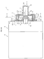
- FIG. 14 and FIG. 15 show the overall structure of a clutch device which employs a reverse input blocking clutch C (lock type) as described above.
- This clutch device is assembled into a single unit comprising a motor M, a reduction gear R, and the reverse input blocking clutch C.
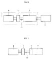
- This clutch device functions as a rotational driving device for generating rotational torque, and torque generated by the motor M is decelerated by the reduction gear R, and is subsequently transmitted from an output shaft R1 of the reduction gear R, through the reverse input blocking clutch C, and input into an output side mechanism O (refer to FIG. 17 and FIG. 18).
- the mirror to be driven such as a door mirror
- the output shaft R1 of the reduction gear R is inserted into a connector 1f of the input member 1.
- the outer periphery of the tip of the output shaft R1 is a polygonal shape, such as a square shape, which corresponds with the internal surface of the connector 1f, and each side of the square forms one of four flat surfaces. Engagement between each of the flat surfaces formed on the output shaft R1 with the corresponding flat surfaces 1f1 of the connector 1f causes the output shaft R1 and the input member 1 to be connected in such a manner that prevents relative rotation.
- An output shaft section 2b of the output member 2 is connected to the driven member (not shown in the drawings) of the output side mechanism O.
- the example is shown in which the end section of the output shaft section 2b is a circular cylindrical surface, although either one, or a plurality of flat surfaces 2b1 can also be formed on this end section, in the same manner as was shown in the first embodiment.
- the reverse input blocking clutch C can be fixed directly to the reduction gear R.
- the device for fixing the reverse input blocking clutch C to the reduction gear R is not restricted to bolts however, and any other suitable device can also be selected.
- the reverse input blocking clutch C can also be fixed to a commercially available reduction gear motor in which the motor M and the reduction gear R have already been assembled.
- the reverse input blocking clutch described above is not restricted to use in only vehicle mirror driving devices, and can also be used in a wide variety of other mechanisms and devices.
- Other examples include folding devices (such as a bed, a seat or the joints of a robot) which generate an angular displacement, raising and lowering devices (such as an elevator, a jack, or the window glass in a vehicle) which generate a linear displacement, opening and closing devices (such as a door, a shutter, a sunroof, or an electric sliding door), and rotational devices (such as an electric power steering device, a bicycle sprocket, an electric wheelchair, an electric vehicle, and the rear wheels of a vehicle with four wheel steering [which uses a ball screw]).
- folding devices such as a bed, a seat or the joints of a robot
- raising and lowering devices such as an elevator, a jack, or the window glass in a vehicle
- opening and closing devices such as a door, a shutter, a sunroof, or an electric sliding door
- the output member 2 can be locked with respect to reverse input torque from the screw section (which corresponds with the driven member of the output side mechanism O), thereby preventing reverse input torque returning to the motor side of the device.
- a reverse input blocking clutch C described above if a reverse input blocking clutch C described above is positioned between the motor and the chuck, then the output member can be locked with respect to reverse input torque applied by the chuck, and so having screwed in a screw electrically, the screw can be further tightened by hand (by rotating the entire tool), thereby increasing the functionality of the tool.
- a toothed section 11b is formed at the outer periphery of one edge of the input outer ring 11. As shown in FIG. 18, this toothed section 11b meshes with a driving gear 5 attached to the output shaft of the motor M to form the reduction gear R.
- the reduction gear R is not restricted to the configuration shown in the figure, and may adopt any suitable configuration.
- the toothed section 11b may be formed directly on the outer periphery of the input outer ring 11 using a metallic material such as hardened steel, or may also be formed as a separate member which is subsequently fixed to the outside of the input outer ring 11.
- a collar 11c which protrudes radially inward is formed on one edge of the inner perimeter of the input outer ring 11. At one position in the circumference of this collar 11c, a notch 11d is formed which extends the entire length of the collar 11c in an axial direction.
- the output inner ring 12 is positioned inside the input outer ring 11.
- This output inner ring 12 comprises a cylindrical section 12a facing the inner surface of the input outer ring 11, and a shaft section 12b which extends out in an axial direction.
- the outer periphery of the cylindrical section 12a is formed in a circular cylindrical shape.
- the inner surface of the input outer ring 11 is provided with a plurality (the same number as the number of rollers 13) of cam surfaces 11a, which are formed with equidistance around the periphery, and which together with the outer surface of the cylindrical section 12a of the output inner ring 12 form wedge shaped gaps s1 which reduce in width symmetrically in both the forward and reverse rotational directions.
- Each wedge shaped gap s1 has a width at the center point thereof in a circumferential direction c1 which is larger than the diameter of the roller 13, and the wedge shaped gap s1 reduces in width symmetrically in both the forward and reverse rotational directions from this circumferential center point c1.
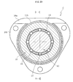
- the centering spring 15 is constructed from a plate spring which is bent to a substantially U shape. As can be seen in FIG. 19 and FIG. 20, once the positions of the notch 11d in the input outer ring 11 and the notch 14b in the retainer 14 have been aligned in a circumferential direction, this centering spring 15 is engaged into both these notches 11d, 14b, with the two tips of the U shape able to expand and contract in a circumferential direction, and with the bottom 15a of the U shape facing inward.
- This centering spring 15 performs the function of elastically connecting the retainer 14 and the input outer ring 11 in a rotational direction, and also performs the function of positioning (centering) the retainer 14 with respect to the input outer ring 11 so that the rollers 13 accommodated within the pockets 14a of the retainer 14 are positioned at the respective circumferential center points c1 of the wedge shaped gaps s1.
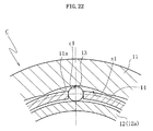
- FIG. 22 shows the state in which the retainer 14 has been centered by the centering spring 15, and in this state, the circumferential centers of the pockets 14a of the retainer 14 coincide with the circumferential center positions of the cam surfaces 11a of the input outer ring 11, and the roller 13 are positioned at the respective circumferential center points c1 of the wedge shaped gaps s1.
- the first side plate 16a and the second side plate 16b are members of the stationary system (the member which does not rotate), and are formed from either press worked metal plate or molded resin. As shown in FIG. 19, these two side plates 16a, 16b are fastened together as a single unit using bolts or the like, with the structural elements of the clutch (the input outer ring 11, the output inner ring 12, the rollers 13, the retainer 14, the centering spring 15 and the sliding spring 17) housed between the two plates.
- the first side plate 16a comprises a cylindrical section 16a1 for housing the other end of the retainer 14 and the sliding spring 17, and a support section 16a2 which extends radially inward from the other edge of the cylindrical section 16a1.
- the support section 16a2 faces the edge surface of the cylindrical section 12a of the output inner ring 12 in an axial direction, and the inner surface of the support section 16a2 is pressed against the edge surface of the cylindrical section 12a.
- the second side plate 16b comprises a cylindrical section 16b1 for housing the input outer ring 11, and a support section 16b2 positioned inside the cylindrical section 16b1.
- the shaft section 12b of the output inner ring 12 is inserted inside the support section 16b2, and this support section 16b2 functions as a bearing (a sliding bearing) for supporting the shaft section 12b in such a manner that allows free rotation in a radial direction.
- a portion of the cylindrical section 16b1 of the second side plate 16b is cut away, and within this cut away portion, the toothed section 11b of the input outer ring 11 meshes with the driving gear 5 shown in FIG. 18.
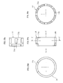
- the sliding spring 17 is a sliding member which slides relative to the first side plate 16a, and in this particular embodiment is formed as an open ring shaped spring member. As can be seen in FIG. 25, this sliding spring 17 comprises a ring shaped sliding section 17a, and engagement sections 17b, 17c formed by bending the two tips of the sliding section 17a radially inwards.
- the sliding section 17a is squeezed slightly closed and pushed inside the inner perimeter of the of the cylindrical section 16a1 of the first side plate 16a, and is held in elastic contact with the inner surface of the cylindrical section 16a1.
- the engagement sections 17b, 17c are both inserted into the notch 14c extending in a circumferential direction around the other edge of the retainer 14, and in this state, the distance between the engagement sections 17b, 17c in a circumferential direction is smaller than the circumferential length of the notch 14c.
- the retainer 14 In the initial state prior to the input of rotational torque at the input outer ring 11, the retainer 14 is centered by the centering spring 15 as shown in FIG. 22. Consequently, the rollers 13 accommodated within the pockets 14a of the retainer 14 are positioned at the circumferential center points c1 of the wedge shaped gaps s1 formed between the cam surfaces 11a of the input outer ring 11 and the cylindrical section 12a of the output inner ring 12.
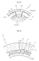
- the edge surface 14d of the retainer 14 engages with the engagement member 17c of the sliding spring 17 and causes the sliding spring 17 to also rotate.
- the sliding spring 17 slides around the inner perimeter of the cylindrical section 16a1 of the first side plate 16a and is subjected to sliding frictional resistance from the stationary side. This sliding frictional resistance is transmitted to the retainer 14 via the engagement member 17c, and acts as resistance to the rotation of the retainer 14.
- the rotational resistance (torque) on the retainer 14 resulting from the sliding frictional resistance of the sliding spring 17 is set to a greater value than the elasticity (spring torque) of the centering spring 15, then the centering spring 15 undergoes an elastic deformation, and the retainer 14 develops a rotational lag relative to the input outer ring 11 equivalent to the amount of elastic deformation.
- the roller 13 When the input outer ring 11 stops, the restoring force of the centering spring 15 causes the roller 13 to disengage from the wedge shaped gap s1 and return to the circumferential center point c1 of the wedge shaped gap s1.
- the roller 13 can be disengaged from the wedge shaped gap s1 by applying a rotational torque in a counter clockwise direction (the opposite direction to the input rotational torque) to the input outer ring 11.
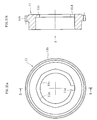
- the restraining means 20 is a device for holding the mirror 30 in a storage position or a working position, by causing an elastic engagement between a concave engagement member 21 provided on either one of the stationary member and the output inner ring 12, and a convex engagement member 22 provided on the other member.
- Each convex engagement member 22 is formed from a steel ball, for example, which is housed within an axial direction aperture 23 formed in the end surface of the cylindrical section 12a of the output inner ring 12, and retained in place by a second elastic member 24 comprising a coiled spring or the like.
- convex engagement members 22 are provided at four positions spaced at equal 90° intervals in a circumferential direction, in the same manner as the concave engagement members 21.
- the convex engagement members 22 are permanently pressed against the surface of the support section 16a2 by the elastic force of the elastic members 24, and each of the concave engagement members 21 is positioned at a point within the rotational locus of a convex engagement member 22. Consequently, each convex engagement member 22 either slides or rolls across the inner surface of the support section 16a2 as the output inner ring 12 rotates, and upon reaching a concave engagement member 21, projects outward and engages elastically with that concave engagement member 21.
- the concave engagement members 21 and the convex engagement members 22 engage elastically, retaining the mirror 30 at one of the respective positions. Because the aforementioned reverse input blocking clutch C which enables the output inner ring 12 to slip freely with respect to a reverse input torque is connected to the mirror 30, there is a danger that vehicle vibrations or wind pressure during operation of the vehicle may cause the mirror 30 to rotate, producing a positional displacement. However, because a clutch device according to the present invention is also provided with the aforementioned restraining means 20, the mirror 30 is able to overcome this type of external force, and remain reliably fixed at each of the prescribed positions.
- the convex engagement members 22 are forced into the corresponding concave engagement members 21, and the engagement of the two sets of members determines the rotational angle.
- the increase in torque will cause an increase in the driving current within the motor M, and by detecting this current increase, a determination can be made that the mirror 30 has reached the storage position or the working position, and the motor M can then be stopped based on this information. Consequently, the rotational angle can be detected without the need to provide a separate rotational angle detecting mechanism with a sensor or the like, thereby enabling a low cost electric retractable mirror of compact construction to be provided.
- the concave engagement members 21 can also be generated by forming circular protrusions 26a on the inner surface, as shown in FIG. 27.
- the increase in the motor current value will begin before the engagement of the engagement members 21, 22, and so reliable engagement of the engagement members 21, 22 can be ensured by stopping the motor M at the point where the current value has peaked and is beginning to decline.
- FIG. 28 shows an example in which the concave engagement members 21 are produced by forming two linear protrusions 26b which are orthogonal to the rotational direction of the convex engagement members 22.
- the concave engagement members 21 are provided on the first side plate 16a of the stationary side, and the convex engagement members 22 are provided on the output inner ring 12 of the rotating side, but the opposite case is also possible, wherein the concave engagement members 21 are provided on a rotating member (such as the output inner ring 12) and the convex engagement members 22 are provided on a stationary member (such as the first side plate 16a). Furthermore, in this embodiment four of each of the concave engagement members 21 and the convex engagement members 22 were provided, but provided one of either the convex or concave members is provided at two positions separated by 90°, one or more of the other members will suffice.
Landscapes
- Engineering & Computer Science (AREA)
- General Engineering & Computer Science (AREA)
- Mechanical Engineering (AREA)
- Multimedia (AREA)
- Braking Arrangements (AREA)
- Mechanical Operated Clutches (AREA)
Abstract
Description
Claims (34)
- A reverse input blocking clutch comprising an input member into which torque is input, an output member to which torque is output, a stationary member, locking means provided between said stationary member and said output member for locking said output member and said stationary member with respect to reverse input torque from said output member, lock release means provided on said input member for releasing a locked state produced by said locking means with respect to input torque from said input member, and torque transmission means provided between said input member and said output member for transmitting input torque from said input member to said output member when a locked state produced by said locking means is released,
wherein at least said input member from amongst said input member, said output member and said stationary member is produced by deformation processing of a metal plate. - The reverse input blocking clutch according to claim 1, wherein said input member comprises a connector for connecting an input shaft, and said connector is positioned inside said clutch.
- The reverse input blocking clutch according to claim 2, wherein said connector is provided on a cylindrical section extending in a continuous manner from an inner perimeter of said input member towards an interior of said clutch.
- The reverse input blocking clutch according to claim 2 or claim 3, wherein said connector is provided with at least one flat surface section for engaging with a flat surface on said input shaft.
- The reverse input blocking clutch according to claim 1, wherein said output member incorporates an integrated cylindrical output shaft section.
- The reverse input blocking clutch according to claim 5, wherein one end of said output shaft section is closed.
- The reverse input blocking clutch according to claim 5 or claim 6, wherein said output shaft section comprises at least one flat surface for engaging with a flat surface of another driven member.
- The reverse input blocking clutch according to claim 1, wherein said locking means comprises a circumferential surface provided on said stationary member, a cam surface provided on said output member for forming a wedge shaped gap in directions of both forward and reverse rotation between said output member and said circumferential surface, a pair of engagement members positioned between said cam surface and said circumferential surface, and an elastic member for pressing said pair of engagement members in a direction of said wedge shaped gap,
said lock release means is an engagement element which engages with either one of said pair of engagement members and pushes said engagement member in a direction away from said wedge shaped gap, and
said torque transmission means comprises rotational engagement elements provided on said input member and said output member,
and at neutral positions of said lock release means and said torque transmission means, a gap δ1 in a direction of rotation between said engagement element of said lock release means and said engagement member, and a gap δ2 in a direction of rotation between said engagement elements of said torque transmission means exist in a relationship in which δ1 < δ2. - The reverse input blocking clutch according to claim 8, wherein said torque transmission means comprises a convex section provided on either one of said input member and said output member, and a matching concave section provided on said other member.
- The reverse input blocking clutch according to claim 9, wherein said convex section is a protrusion provided on said output member, and said concave section is a notch provided in said input member.
- The reverse input blocking clutch according to claim 9, wherein said convex section is a protrusion provided on said output member, and said concave section is an aperture provided in said input member.
- The reverse input blocking clutch according to claim 10 or claim 11, wherein said protrusion protrudes out in a radial direction.
- The reverse input blocking clutch according to claim 10 or claim 11, wherein said protrusion protrudes out in an axial direction.
- The reverse input blocking clutch according to claim 8, wherein said elastic member comprises a base and a tongue section extending from said base in one axial direction, and said tongue section is positioned between said pair of engagement members and pushes said pair of engagement members mutually apart.
- The reverse input blocking clutch according to claim 14, wherein said base is a ring shape, and a plurality of said tongues are positioned around a circumference of said ring.
- The reverse input blocking clutch according to claim 8, wherein said engagement members are rollers.
- The reverse input blocking clutch according to claim 1, further comprising a fixed side plate fixed to said stationary member, wherein said fixed side plate comprises a metal plate which has undergone deformation processing.
- The reverse input blocking clutch according to claim 17, wherein said fixed side plate comprises a bearing for supporting an input shaft in a radial direction.
- The reverse input blocking clutch according to claim 18, wherein said bearing is provided on a cylindrical section extending in a continuous manner from an inner perimeter of said fixed side plate towards an interior of said clutch.
- A clutch device comprising an integrated unit incorporating a rotational driving source, and
a reverse input blocking clutch comprising an input member into which torque from said rotational driving source is input, an output member to which torque is output, a stationary member, locking means provided between said stationary member and said output member for locking said output member and said stationary member with respect to reverse input torque from said output member, lock release means provided on said input member for releasing a locked state produced by said locking means with respect to input torque from said input member, and torque transmission means for transmitting input torque from said input member to said output member when a locked state produced by said locking means is released. - A clutch device comprising an integrated unit incorporating a reverse input blocking clutch comprising an input member into which torque from a rotational driving source is input, an output member to which torque is output, a stationary member, locking means provided between said stationary member and said output member for locking said output member and said stationary member with respect to reverse input torque from said output member, lock release means provided on said input member for releasing a locked state produced by said locking means with respect to input torque from said input member, and torque transmission means for transmitting input torque from said input member to said output member when a locked state produced by said locking means is released, and
an output mechanism for performing a desired operation using torque transmitted to said output member of said reverse input blocking clutch. - The clutch device according to claim 20 or claim 21, wherein at least said input member from amongst said input member, said output member and said stationary member of said reverse input blocking clutch is produced by deformation processing of a metal plate.
- The clutch device according to claim 20 or claim 21, wherein said input member of said reverse input blocking clutch comprises a connector for connecting an output shaft of a rotational driving source, and said connector is positioned inside said clutch.
- The clutch device according to claim 23, wherein said connector is provided on a cylindrical section extending in a continuous manner from an inner perimeter of said input member towards an interior of said clutch.
- The clutch device according to claim 23, wherein said connector is provided with at least one flat surface section for engaging with a flat surface on an output shaft of a rotational driving source.
- The clutch device according to claim 20 or claim 21, wherein said locking means of said reverse input blocking clutch comprises a circumferential surface provided on said stationary member, a cam surface provided on said output member for forming a wedge shaped gap in directions of both forward and reverse rotation between said output member and said circumferential surface, a pair of engagement members positioned between said cam surface and said circumferential surface, and an elastic member for pressing said pair of engagement members in a direction of said wedge shaped gap,
said lock release means is an engagement element which engages with either one of said pair of engagement members and pushes said engagement member in a direction away from said wedge shaped gap, and
said torque transmission means comprises rotational engagement elements provided on said input member and said output member,
and at neutral positions of said lock release means and said torque transmission means, a gap δ1 in a direction of rotation between said engagement element of said lock release means and said engagement member, and a gap δ2 in a direction of rotation between said engagement elements of said torque transmission means exist in a relationship in which δ1 < δ2. - A clutch device for moving a driven member between at least two predetermined prescribed positions, incorporating
a rotational driving source,
a reverse input blocking clutch comprising an input member into which torque from said rotational driving source is input and an output member connected to said driven member, for transmitting input torque applied to said input member to said output member while blocking transmission of reverse input torque applied at said output member to said input member and permitting slipping of said output member, and
restraining means for elastically restraining rotation of said output member at each of said prescribed positions. - The clutch device according to claim 27, wherein said reverse input blocking clutch further comprises a torque transmission member which can be engaged with and disengaged from said input member and said output member in directions of both forward and reverse rotation, a retainer for retaining said torque transmission member and controlling engagement and disengagement of said torque transmission member through relative rotation with respect to said input member, a first elastic member for connecting said input member and said retainer in a rotational direction, a stationary member, and rotational resistance application means for applying frictional resistance to said retainer for rotation of said retainer relative to said stationary member.
- The clutch device according to claim 27, wherein said restraining means comprises a concave engagement section provided on either one of said output member and said stationary member, and a convex engagement section provided on said other member, said engagement section on said stationary member is positioned in a rotational locus of said engagement section on a rotating side, and at each of said prescribed positions, and said concave engagement section and said convex engagement section engage elastically and restrict rotation of said output member.
- The clutch device according to claim 29, wherein said output member and said stationary member oppose one another in an axial direction, and said concave engagement section and said convex engagement section are positioned within said opposing section.
- The clutch device according to claim 29, wherein a motor is stopped at a point where a driving current of said motor increases with engagement of said concave engagement section and said convex engagement section.
- The clutch device according to claim 28, wherein said rotational resistance application means comprises a sliding member capable of engaging in a circumferential direction with either one of said retainer and said stationary member, and sliding relative to said other member.
- The clutch device according to claim 32, wherein said sliding member slides relative to said stationary member while being engaged in a circumferential direction with said retainer.
- The clutch device according to claim 27, wherein said driven member is a mirror of a vehicle.
Priority Applications (1)
| Application Number | Priority Date | Filing Date | Title |
|---|---|---|---|
| EP04076428A EP1457700B1 (en) | 2001-03-08 | 2002-03-07 | Reverse input blocking clutch |
Applications Claiming Priority (6)
| Application Number | Priority Date | Filing Date | Title |
|---|---|---|---|
| JP2001065239 | 2001-03-08 | ||
| JP2001065239A JP4009429B2 (en) | 2001-03-08 | 2001-03-08 | Reverse input prevention clutch |
| JP2001242258 | 2001-08-09 | ||
| JP2001242232 | 2001-08-09 | ||
| JP2001242232A JP2003056596A (en) | 2001-08-09 | 2001-08-09 | Rotating device with clutch |
| JP2001242258A JP2003056602A (en) | 2001-08-09 | 2001-08-09 | Rotary drive |
Related Child Applications (1)
| Application Number | Title | Priority Date | Filing Date |
|---|---|---|---|
| EP04076428A Division EP1457700B1 (en) | 2001-03-08 | 2002-03-07 | Reverse input blocking clutch |
Publications (3)
| Publication Number | Publication Date |
|---|---|
| EP1239178A2 true EP1239178A2 (en) | 2002-09-11 |
| EP1239178A3 EP1239178A3 (en) | 2002-10-02 |
| EP1239178B1 EP1239178B1 (en) | 2004-12-15 |
Family
ID=27346195
Family Applications (2)
| Application Number | Title | Priority Date | Filing Date |
|---|---|---|---|
| EP04076428A Expired - Lifetime EP1457700B1 (en) | 2001-03-08 | 2002-03-07 | Reverse input blocking clutch |
| EP02251610A Expired - Lifetime EP1239178B1 (en) | 2001-03-08 | 2002-03-07 | Reverse input blocking clutch |
Family Applications Before (1)
| Application Number | Title | Priority Date | Filing Date |
|---|---|---|---|
| EP04076428A Expired - Lifetime EP1457700B1 (en) | 2001-03-08 | 2002-03-07 | Reverse input blocking clutch |
Country Status (4)
| Country | Link |
|---|---|
| US (2) | US6695118B2 (en) |
| EP (2) | EP1457700B1 (en) |
| CN (1) | CN1288360C (en) |
| DE (2) | DE60202229T2 (en) |
Cited By (6)
| Publication number | Priority date | Publication date | Assignee | Title |
|---|---|---|---|---|
| WO2005108814A1 (en) * | 2004-05-06 | 2005-11-17 | Hans Heidolph Gmbh & Co. Kg | Anti-reactive modular gear unit and locking coupling |
| DE102005030719A1 (en) * | 2005-07-01 | 2007-01-04 | Schaeffler Kg | Silent ratchet for a seat adjusting device in a vehicle comprises a friction element in the form of an annular seal arranged in an annular groove of a drive element |
| CN101922523A (en) * | 2009-06-09 | 2010-12-22 | 欧利生电气株式会社 | Reverse input to disengage clutch |
| WO2011161394A1 (en) | 2010-06-22 | 2011-12-29 | Rotork Controls Limited | Improvements in and relating to anti back-drive couplings |
| EP2698280A1 (en) * | 2012-08-14 | 2014-02-19 | Fico Mirrors, S.A. | Double detent folding mirror |
| CN105940246A (en) * | 2014-01-28 | 2016-09-14 | Ntn株式会社 | Reduction gear with brake |
Families Citing this family (26)
| Publication number | Priority date | Publication date | Assignee | Title |
|---|---|---|---|---|
| DE102004062815A1 (en) * | 2004-12-27 | 2006-07-06 | Robert Bosch Gmbh | Load torque lock |
| WO2006115343A1 (en) | 2005-04-07 | 2006-11-02 | Donghwan Byun | Reverse input prevent clutch bearing assembly |
| DE102005023250B4 (en) * | 2005-04-28 | 2017-10-05 | Schaeffler Technologies AG & Co. KG | actuator |
| KR100621347B1 (en) * | 2005-09-20 | 2006-09-07 | 주식회사 만도 | Electric power assist steering in cars |
| US8181763B2 (en) * | 2006-01-31 | 2012-05-22 | Schaeffler Technologies AG & Co. KG | Window winder drive |
| FI118729B (en) | 2006-04-04 | 2008-02-29 | Kone Corp | Arrangement to stop a lift basket in an emergency and lift |
| KR100778560B1 (en) * | 2006-10-16 | 2007-11-22 | 현대자동차주식회사 | Driving system and driving method of vehicle side mirror |
| DE102007017617B4 (en) * | 2006-11-02 | 2016-06-09 | Johnson Controls Gmbh | Adjustment of a motor vehicle seat |
| CN100552250C (en) * | 2007-03-16 | 2009-10-21 | 蔡国法 | Overrunning clutch |
| US8448764B2 (en) * | 2007-12-12 | 2013-05-28 | Ntn Corporation | Rotation transmission device |
| CN103097757B (en) * | 2010-07-16 | 2016-10-12 | 艾拓有限公司 | Self-locking mechanism for valve actuator |
| US8852041B2 (en) * | 2010-09-30 | 2014-10-07 | Shimano, Inc. | Bicycle derailleur with rotation resistance |
| US8870692B2 (en) * | 2010-09-30 | 2014-10-28 | Shimano, Inc. | Bicycle derailleur with rotation resistance |
| DE102011084397A1 (en) * | 2011-10-13 | 2013-04-18 | Schaeffler Technologies AG & Co. KG | Freewheel for use as starter freewheel for starting of internal combustion engine, has two bearing races, where radial outer bearing race is divided in holding ring and bearing race part |
| NL1039622C2 (en) * | 2012-05-23 | 2013-11-26 | Forest Group Nederland Bv | FREE-COUPLING. |
| JP6065505B2 (en) * | 2012-10-03 | 2017-01-25 | 株式会社ジェイテクト | Power generator |
| KR101450625B1 (en) * | 2013-01-25 | 2014-10-15 | 삼성중공업 주식회사 | Trolley |
| CN105393013B (en) * | 2013-07-25 | 2017-08-08 | 丰田自动车株式会社 | clutch |
| WO2015137231A1 (en) * | 2014-03-14 | 2015-09-17 | オリジン電気株式会社 | Reverse input blocking clutch |
| DE102014212863B4 (en) * | 2014-07-02 | 2020-08-20 | Stabilus Gmbh | Flap control |
| NL2018838B1 (en) * | 2017-05-03 | 2018-11-14 | Mci Mirror Controls Int Netherlands B V | Adjustment instrument and method |
| CN110848284A (en) * | 2018-08-20 | 2020-02-28 | 锅屋百泰株式会社 | Motor with reverse input blocking clutch and reverse input blocking clutch |
| WO2020133269A1 (en) * | 2018-12-28 | 2020-07-02 | 深圳配天智能技术研究院有限公司 | Limiting device, mechanical arm, and robot |
| US10711852B1 (en) * | 2019-01-18 | 2020-07-14 | General Electric Company | Locking clutch systems |
| CN112555293A (en) * | 2020-12-21 | 2021-03-26 | 上海探见智能家居有限公司 | Window opening clutch |
| KR20250152436A (en) | 2024-04-16 | 2025-10-23 | 삼성전자주식회사 | Display apparatus |
Family Cites Families (27)
| Publication number | Priority date | Publication date | Assignee | Title |
|---|---|---|---|---|
| US2260119A (en) * | 1940-06-28 | 1941-10-21 | Briggs Mfg Co | Clutch assembly |
| US2449020A (en) * | 1943-06-14 | 1948-09-07 | Automatic Locking Devices Inc | Power drive |
| US2561159A (en) * | 1944-09-14 | 1951-07-17 | Cecil E Walton | Self-locking clutch |
| US3011606A (en) * | 1957-07-26 | 1961-12-05 | Borg Warner | Roller clutch |
| US3005384A (en) * | 1960-08-17 | 1961-10-24 | Royal Engineering Co Inc | Power actuated rear view mirror |
| GB1174226A (en) * | 1968-01-17 | 1969-12-17 | Schaeffler Ohg Industriewerk | Improvements in Jamming-Roller Freewheel Clutches |
| US4070895A (en) * | 1975-09-20 | 1978-01-31 | Tokico Ltd. | Method for manufacturing bottom valve seat |
| US4676089A (en) * | 1985-05-13 | 1987-06-30 | Nevin Donald M | Hub for rotatable tool |
| DE3834198A1 (en) | 1987-10-09 | 1989-04-27 | Ntn Toyo Bearing Co Ltd | CLUTCH |
| JPH01218729A (en) * | 1988-02-29 | 1989-08-31 | Sanden Corp | Manufacture of rotor main body for solenoid clutch |
| DE3839732A1 (en) | 1988-11-24 | 1990-06-07 | Rentrop Hubbert & Wagner | BRAKE FOR AN ADJUSTMENT OF MOTOR VEHICLE SEATS |
| JPH0712509B2 (en) * | 1990-04-17 | 1995-02-15 | 日本精工株式会社 | Outside ring manufacturing method |
| DE9101110U1 (en) * | 1991-02-01 | 1992-02-27 | Schwarzbich, Jörg, 4800 Bielefeld | Gearbox for the transmission of rotary motion in both directions |
| JP2602999Y2 (en) * | 1991-12-26 | 2000-02-07 | 株式会社村上開明堂 | Electric retractable door mirror control device |
| EP0644084B1 (en) * | 1993-09-03 | 1998-05-20 | Ichikoh Industries Limited | Rearview mirror system for vehicles |
| DE9319848U1 (en) * | 1993-12-23 | 1995-01-26 | Schwarzbich, Jörg, 33615 Bielefeld | Seat adjustment |
| DE4447480A1 (en) | 1994-12-24 | 1996-06-27 | Schaeffler Waelzlager Kg | Clamping mechanism preferably provided for seat adjustment |
| US5703732A (en) * | 1995-01-17 | 1997-12-30 | Lowell Engineering Corporation | Exterior mirror with indexing and control pivoting |
| JP3516315B2 (en) * | 1995-07-05 | 2004-04-05 | 本田技研工業株式会社 | Electric power steering device |
| EP0884494A1 (en) * | 1997-06-02 | 1998-12-16 | Ichikoh Industries Limited | Locking mechanism |
| FR2766773B1 (en) * | 1997-07-30 | 1999-10-15 | Faure Bertrand Equipements Sa | LOCKING DEVICE, PARTICULARLY FOR A MOTOR VEHICLE SEAT |
| DE29715257U1 (en) | 1997-08-26 | 1997-12-04 | Atlas Copco Electric Tools GmbH, 71364 Winnenden | Driving device |
| US5952802A (en) * | 1997-12-08 | 1999-09-14 | Delco Electronics Corp. | Method of controlling an automotive mirror |
| DE19854945A1 (en) * | 1998-11-27 | 2000-05-31 | Schaeffler Waelzlager Ohg | Pinch roller switch mechanism |
| AUPP809399A0 (en) * | 1999-01-11 | 1999-02-04 | Britax Rainsfords Pty Ltd | A mirror rotation mechanism |
| US6267218B1 (en) * | 1999-03-12 | 2001-07-31 | INA Wälzlager Schaeffler oHG | Clamp-type locking mechanism |
| EP1097832A3 (en) * | 1999-11-04 | 2002-02-06 | Stant Manufacturing Inc. | Filler neck closure with static charge dissipator |
-
2002
- 2002-03-07 DE DE60202229T patent/DE60202229T2/en not_active Expired - Lifetime
- 2002-03-07 EP EP04076428A patent/EP1457700B1/en not_active Expired - Lifetime
- 2002-03-07 US US10/091,593 patent/US6695118B2/en not_active Expired - Lifetime
- 2002-03-07 EP EP02251610A patent/EP1239178B1/en not_active Expired - Lifetime
- 2002-03-07 DE DE60215854T patent/DE60215854T2/en not_active Expired - Lifetime
- 2002-03-08 CN CNB021067767A patent/CN1288360C/en not_active Expired - Fee Related
-
2003
- 2003-11-10 US US10/703,490 patent/US7117710B2/en not_active Expired - Lifetime
Cited By (11)
| Publication number | Priority date | Publication date | Assignee | Title |
|---|---|---|---|---|
| WO2005108814A1 (en) * | 2004-05-06 | 2005-11-17 | Hans Heidolph Gmbh & Co. Kg | Anti-reactive modular gear unit and locking coupling |
| US7614488B2 (en) | 2004-05-06 | 2009-11-10 | Hans Heidolph Gmbh & Co. Kg | Anti-reactive modular gear unit and locking coupling |
| DE102005030719A1 (en) * | 2005-07-01 | 2007-01-04 | Schaeffler Kg | Silent ratchet for a seat adjusting device in a vehicle comprises a friction element in the form of an annular seal arranged in an annular groove of a drive element |
| CN101922523A (en) * | 2009-06-09 | 2010-12-22 | 欧利生电气株式会社 | Reverse input to disengage clutch |
| CN101922523B (en) * | 2009-06-09 | 2013-03-06 | 欧利生电气株式会社 | Reverse input disconnection clutch |
| WO2011161394A1 (en) | 2010-06-22 | 2011-12-29 | Rotork Controls Limited | Improvements in and relating to anti back-drive couplings |
| GB2494841A (en) * | 2010-06-22 | 2013-03-20 | Rotork Controls | Improvements in and relating to anti back-drive couplings |
| US8950565B2 (en) | 2010-06-22 | 2015-02-10 | Rotork Controls Limited | Anti back-drive couplings |
| EP2698280A1 (en) * | 2012-08-14 | 2014-02-19 | Fico Mirrors, S.A. | Double detent folding mirror |
| CN105940246A (en) * | 2014-01-28 | 2016-09-14 | Ntn株式会社 | Reduction gear with brake |
| EP3101314A4 (en) * | 2014-01-28 | 2017-04-12 | NTN Corporation | Reduction gear with brake |
Also Published As
| Publication number | Publication date |
|---|---|
| EP1457700A1 (en) | 2004-09-15 |
| EP1239178B1 (en) | 2004-12-15 |
| US7117710B2 (en) | 2006-10-10 |
| DE60202229T2 (en) | 2005-12-15 |
| US20020125099A1 (en) | 2002-09-12 |
| US20040089049A1 (en) | 2004-05-13 |
| DE60215854D1 (en) | 2006-12-14 |
| CN1288360C (en) | 2006-12-06 |
| CN1374465A (en) | 2002-10-16 |
| US6695118B2 (en) | 2004-02-24 |
| DE60215854T2 (en) | 2007-06-28 |
| DE60202229D1 (en) | 2005-01-20 |
| EP1239178A3 (en) | 2002-10-02 |
| EP1457700B1 (en) | 2006-11-02 |
Similar Documents
| Publication | Publication Date | Title |
|---|---|---|
| EP1239178B1 (en) | Reverse input blocking clutch | |
| US4852707A (en) | Reversible self-locking clutch | |
| EP2055530B1 (en) | Motor-driven actuator | |
| JP7052529B2 (en) | Actuator and steer-by-wire steering system | |
| US20080178643A1 (en) | Assembling method of electric steering lock device | |
| US8256699B2 (en) | Webbing take-up device | |
| JP7060169B2 (en) | Reverse input cutoff clutch | |
| US20090309345A1 (en) | Device for restraining a vehicle occupant | |
| JP2003276565A (en) | Electric steering lock device | |
| EP3305606B1 (en) | Seatbelt retractor | |
| KR101436944B1 (en) | Adjusting device for a vehicle seat having a self-adjusting brake | |
| US6748774B2 (en) | Forward firing shaft lock mechanism | |
| CN115013500B (en) | Locking differential and vehicle having the same | |
| JP2003056596A (en) | Rotating device with clutch | |
| JP2004161244A (en) | Position adjusting mechanism for seat of vehicle | |
| JP2009035104A (en) | Steering device | |
| US12031624B2 (en) | Electromechanical power steering having a helical-gear transmission and a transmission housing | |
| CN100392292C (en) | Worm gear mechanism and electric power steering equipped with worm gear mechanism | |
| JP2008308054A (en) | Vehicle steering system | |
| JP2000234971A (en) | Torque sensor and electric power steering device provided with the torque sensor | |
| JP2007507678A (en) | Planetary gear device having movable connecting element and operation device | |
| JPH0288346A (en) | Steering lock device | |
| US9302646B2 (en) | Seat belt retractor | |
| JP2008179170A (en) | Vehicle steering system | |
| JP2003341531A (en) | Auxiliary steering force transmission mechanism for electric power steering device |
Legal Events
| Date | Code | Title | Description |
|---|---|---|---|
| PUAI | Public reference made under article 153(3) epc to a published international application that has entered the european phase |
Free format text: ORIGINAL CODE: 0009012 |
|
| PUAL | Search report despatched |
Free format text: ORIGINAL CODE: 0009013 |
|
| AK | Designated contracting states |
Kind code of ref document: A2 Designated state(s): AT BE CH CY DE DK ES FI FR GB GR IE IT LI LU MC NL PT SE TR |
|
| AX | Request for extension of the european patent |
Free format text: AL;LT;LV;MK;RO;SI |
|
| AK | Designated contracting states |
Kind code of ref document: A3 Designated state(s): AT BE CH CY DE DK ES FI FR GB GR IE IT LI LU MC NL PT SE TR |
|
| AX | Request for extension of the european patent |
Free format text: AL;LT;LV;MK;RO;SI |
|
| RIC1 | Information provided on ipc code assigned before grant |
Free format text: 7F 16D 41/10 A, 7B 60R 1/076 B, 7B 60R 1/074 B |
|
| 17P | Request for examination filed |
Effective date: 20030325 |
|
| 17Q | First examination report despatched |
Effective date: 20030430 |
|
| AKX | Designation fees paid |
Designated state(s): DE FR GB |
|
| GRAP | Despatch of communication of intention to grant a patent |
Free format text: ORIGINAL CODE: EPIDOSNIGR1 |
|
| GRAS | Grant fee paid |
Free format text: ORIGINAL CODE: EPIDOSNIGR3 |
|
| GRAA | (expected) grant |
Free format text: ORIGINAL CODE: 0009210 |
|
| AK | Designated contracting states |
Kind code of ref document: B1 Designated state(s): DE FR GB |
|
| REG | Reference to a national code |
Ref country code: GB Ref legal event code: FG4D |
|
| REF | Corresponds to: |
Ref document number: 60202229 Country of ref document: DE Date of ref document: 20050120 Kind code of ref document: P |
|
| PLBE | No opposition filed within time limit |
Free format text: ORIGINAL CODE: 0009261 |
|
| STAA | Information on the status of an ep patent application or granted ep patent |
Free format text: STATUS: NO OPPOSITION FILED WITHIN TIME LIMIT |
|
| 26N | No opposition filed |
Effective date: 20050916 |
|
| ET | Fr: translation filed | ||
| REG | Reference to a national code |
Ref country code: FR Ref legal event code: PLFP Year of fee payment: 15 |
|
| REG | Reference to a national code |
Ref country code: FR Ref legal event code: PLFP Year of fee payment: 16 |
|
| REG | Reference to a national code |
Ref country code: FR Ref legal event code: PLFP Year of fee payment: 17 |
|
| PGFP | Annual fee paid to national office [announced via postgrant information from national office to epo] |
Ref country code: DE Payment date: 20190219 Year of fee payment: 18 Ref country code: GB Payment date: 20190306 Year of fee payment: 18 |
|
| PGFP | Annual fee paid to national office [announced via postgrant information from national office to epo] |
Ref country code: FR Payment date: 20190213 Year of fee payment: 18 |
|
| REG | Reference to a national code |
Ref country code: DE Ref legal event code: R119 Ref document number: 60202229 Country of ref document: DE |
|
| PG25 | Lapsed in a contracting state [announced via postgrant information from national office to epo] |
Ref country code: DE Free format text: LAPSE BECAUSE OF NON-PAYMENT OF DUE FEES Effective date: 20201001 Ref country code: FR Free format text: LAPSE BECAUSE OF NON-PAYMENT OF DUE FEES Effective date: 20200331 |
|
| GBPC | Gb: european patent ceased through non-payment of renewal fee |
Effective date: 20200307 |
|
| PG25 | Lapsed in a contracting state [announced via postgrant information from national office to epo] |
Ref country code: GB Free format text: LAPSE BECAUSE OF NON-PAYMENT OF DUE FEES Effective date: 20200307 |