CN1288360C - Clutch for cutting off reverse input and clutch arrangement with the same clutch - Google Patents
Clutch for cutting off reverse input and clutch arrangement with the same clutch Download PDFInfo
- Publication number
- CN1288360C CN1288360C CNB021067767A CN02106776A CN1288360C CN 1288360 C CN1288360 C CN 1288360C CN B021067767 A CNB021067767 A CN B021067767A CN 02106776 A CN02106776 A CN 02106776A CN 1288360 C CN1288360 C CN 1288360C
- Authority
- CN
- China
- Prior art keywords
- clutch
- output terminal
- input
- input end
- torque
- Prior art date
- Legal status (The legal status is an assumption and is not a legal conclusion. Google has not performed a legal analysis and makes no representation as to the accuracy of the status listed.)
- Expired - Fee Related
Links
Images


Classifications
-
- F—MECHANICAL ENGINEERING; LIGHTING; HEATING; WEAPONS; BLASTING
- F16—ENGINEERING ELEMENTS AND UNITS; GENERAL MEASURES FOR PRODUCING AND MAINTAINING EFFECTIVE FUNCTIONING OF MACHINES OR INSTALLATIONS; THERMAL INSULATION IN GENERAL
- F16D—COUPLINGS FOR TRANSMITTING ROTATION; CLUTCHES; BRAKES
- F16D41/00—Freewheels or freewheel clutches
- F16D41/06—Freewheels or freewheel clutches with intermediate wedging coupling members between an inner and an outer surface
- F16D41/08—Freewheels or freewheel clutches with intermediate wedging coupling members between an inner and an outer surface with provision for altering the freewheeling action
- F16D41/10—Freewheels or freewheel clutches with intermediate wedging coupling members between an inner and an outer surface with provision for altering the freewheeling action with self-actuated reversing
-
- B—PERFORMING OPERATIONS; TRANSPORTING
- B60—VEHICLES IN GENERAL
- B60R—VEHICLES, VEHICLE FITTINGS, OR VEHICLE PARTS, NOT OTHERWISE PROVIDED FOR
- B60R1/00—Optical viewing arrangements; Real-time viewing arrangements for drivers or passengers using optical image capturing systems, e.g. cameras or video systems specially adapted for use in or on vehicles
- B60R1/02—Rear-view mirror arrangements
- B60R1/06—Rear-view mirror arrangements mounted on vehicle exterior
- B60R1/062—Rear-view mirror arrangements mounted on vehicle exterior with remote control for adjusting position
- B60R1/07—Rear-view mirror arrangements mounted on vehicle exterior with remote control for adjusting position by electrically powered actuators
- B60R1/074—Rear-view mirror arrangements mounted on vehicle exterior with remote control for adjusting position by electrically powered actuators for retracting the mirror arrangements to a non-use position alongside the vehicle
-
- B—PERFORMING OPERATIONS; TRANSPORTING
- B60—VEHICLES IN GENERAL
- B60R—VEHICLES, VEHICLE FITTINGS, OR VEHICLE PARTS, NOT OTHERWISE PROVIDED FOR
- B60R1/00—Optical viewing arrangements; Real-time viewing arrangements for drivers or passengers using optical image capturing systems, e.g. cameras or video systems specially adapted for use in or on vehicles
- B60R1/02—Rear-view mirror arrangements
- B60R1/06—Rear-view mirror arrangements mounted on vehicle exterior
- B60R1/076—Rear-view mirror arrangements mounted on vehicle exterior yieldable to excessive external force and provided with an indexed use position
-
- F—MECHANICAL ENGINEERING; LIGHTING; HEATING; WEAPONS; BLASTING
- F16—ENGINEERING ELEMENTS AND UNITS; GENERAL MEASURES FOR PRODUCING AND MAINTAINING EFFECTIVE FUNCTIONING OF MACHINES OR INSTALLATIONS; THERMAL INSULATION IN GENERAL
- F16D—COUPLINGS FOR TRANSMITTING ROTATION; CLUTCHES; BRAKES
- F16D41/00—Freewheels or freewheel clutches
- F16D41/06—Freewheels or freewheel clutches with intermediate wedging coupling members between an inner and an outer surface
- F16D41/08—Freewheels or freewheel clutches with intermediate wedging coupling members between an inner and an outer surface with provision for altering the freewheeling action
- F16D41/10—Freewheels or freewheel clutches with intermediate wedging coupling members between an inner and an outer surface with provision for altering the freewheeling action with self-actuated reversing
- F16D41/105—Freewheels or freewheel clutches with intermediate wedging coupling members between an inner and an outer surface with provision for altering the freewheeling action with self-actuated reversing the intermediate members being of circular cross-section, of only one size and wedging by rolling movement not having an axial component between inner and outer races, one of which is cylindrical
Abstract
A reverse input blocking clutch comprises, as main elements, an input member (1), an output member (2), a stationary member (3) for constraining the revolutions, locking means, lock release means and torque transmission means. By forming the input member (1), the output member (2), the stationary member (3) and a fixed side plate (4) from metal plates such as press worked steel plates, a compact, lightweight and low cost reverse input blocking clutch is provided. Reverse input torque from the output member (2) is locked in both the forward and reverse rotational directions relative to the stationary member (3), by rollers (6) which function as the locking means. Input torque from the input member (1) in both the forward and reverse rotational directions is transmitted to the output member (2) via apertures (1d) and protrusions which function as the torque transmission means.
Description
Technical field
The present invention relates to the clutch device that oppositely input intercepts clutch and uses this clutch.
Background technique
Finish the device that requires action for the input torque of the source of rotational drive of coming motor freely etc. is passed to output terminal mechanism, people wish can intercept reverse input torque and pass to input end from output terminal mechanism when driving power source and stop operating.
For example, require to possess when the driving power source stops, can keeping the function of the invariant position of output terminal mechanism.With the electric shutter is example, after the input torque forward or backwards of drive motor inputs to the output terminal switching mechanism, shutter just carries out switch motion, but in the process of switch motion because of unpredictable thing (as having a power failure etc.) when causing driving source to stop, because of the shutter deadweight, this shutter descends, and its decline and the opposing torque that produces can anti-pass be given input end then might cause damage to input end mechanism.Therefore, need a kind of mechanism that possesses following function, this function is meant the position that keeps shutter, makes from the reverse input torque of shutter and can anti-pass not give input end.
For the mechanism of the motor revolution being slowed down, during from the reverse input torque of output terminal, might produce following problem with any reason by speed reducer.
A), when having used the gear worm device, because can not importing opposite force, this gearing causes rotation, so can bear bigger load on worm gear or the worm tooth as speed reducer.Huge especially thrust load can affact on the worm screw.Therefore, support the bearing of tooth or worm screw that damaged danger is arranged,, just need to increase mechanism perhaps in order to prevent the generation of this breakage.
B) even use the speed reducer of horizontal gear or helical gear etc., when reverse input torque excessive (for example, effect has when impacting oppositely input), tooth is easily impaired.
In order to address the above problem, the mechanism that just must have following function, this function is should guarantee can transmit input torque to output terminal as the motor of input end, and, also to make reverse input torque can not pass to the motor and the speed reducer of input end with respect to reverse input torque locking output terminal from output terminal.
In recent years, installed electric sealed reflecting mirror on the vehicles such as a lot of automobiles, this electric sealed reflecting mirror is that power drives the reflecting mirror that is contained on the door with the motor, and can be in the swing of doing 90 ° towards vehicle side between open use position and the accommodated position turned up.As electric sealed reflecting mirror, Figure 29 illustrates and (has for example disclosed a kind of known driving mechanism, Te Kaiping 11-51092 communique), when this driving mechanism drives this reflecting mirror at motor 41, reflecting mirror 42 is rotated lightly, when external force acts on the reflecting mirror 42, external force is intercepted by means of the effect of clutch 43, thereby reflecting mirror 42 is firmly fixed, and external force can not affact on the motor 41.
Yet in the driving mechanism of above-mentioned communique record, because be subjected to the external force effect, when oppositely input torque affacted on the reflecting mirror, reflecting mirror was not being fixed firmly and can rotated, so can not absorb external force, caused reflecting mirror etc. impaired easily.In order to address this problem, necessarily require the input torque as the motor of input end to be passed to reflecting mirror into output terminal, and, reflecting mirror can be dallied with respect to reverse input torque, pass to input end thereby intercept reverse input torque.
In addition, a kind of operation equipment is disclosed in WO-99/10132A1.The input end parts 3 of this device are not formed by sheet metal, and except be provided as the column 10 of latch-release device on input end parts 3, also are provided with the jut 11 as torque transmitter.Under the situation that such two kinds of axial projections (column 10 and jut 11) is set, even use sheet metal also to be difficult to input end parts 3 punch process.
In addition, in the disclosed technology of EP-0884494A1, a certain side in the parts 30 and 40 is taken as the input end parts, and parts 30 and 40 both sides are not formed by sheet metal.And, on parts 40, formed jut 43 as torque transmitter with latch-release device 42.Therefore, even use sheet metal also to be difficult to parts 40 punch process.
In addition, in the disclosed technology of US-5896973A, on input end parts 5, be formed with latch-release device 27 and as the jut 19 of torque transmitter.Therefore be difficult to form input end parts 5 by the punch process of sheet metal.
In the disclosed technology of EP-0370502A2, input end parts 11 are not formed by sheet metal.And, on input end parts 11, be formed with latch-release device 36 and as the jut 27 of torque transmitter.Therefore, even use sheet metal also to be difficult to input end parts 11 punch process.
In addition, identical at the disclosed clutch of EP-0752360A1 with the mechanism of above-mentioned EP-0370502A2, even therefore use sheet metal also to be difficult to input end parts 11 punch process.
Summary of the invention
The object of the present invention is to provide a kind of above-mentioned functions that has, and, the clutch device that compact structure, reverse input in light weight, that price is low intercept clutch and use this clutch.
In order to address the above problem, structure of the present invention possesses: the input end parts of input torque, the output terminal component of output torque, the Stationary side parts that restriction is rotated, be arranged between Stationary side parts and the output terminal component, for the locking device that locks output terminal component and Stationary side parts from the reverse input torque of output terminal component, be arranged on the input end parts, for the latch-release device of removing the lock state of realizing by locking device from the input torque of input end parts, be arranged between input end parts and the output terminal component, when having removed the lock state of locking device enforcement, input torque from the input end parts is passed to the torque transmitter of output terminal component, wherein, described latch-release device is made of the column that extends vertically of being located at the input end parts; Described torque transmitter is made of with the grooving portion or the hole portion that are located at the input end parts the jut of being located at output terminal component; In described input end parts, output terminal component and the Stationary side parts, the input end parts are the punch process part of sheet metal at least.
Here [locking device] comprises by the wedge inlay resultant force, concavo-convex inlay resultant force, frictional force, magnetic force, electromagnetic force, hydrodynamic pressure, fluid viscosity resistance, fine particle medium etc. provide the device of restraining force, but from simplified construction and control mechanism, action is level and smooth, the considerations such as aspect of cost, and the device of rotational restraint power preferably is provided by the wedge inlay resultant force.Concrete formation is to form wedge gap between output terminal component and Stationary side parts, makes counterpart carry out the chimeric disengaging of wedge with respect to this wedge gap, switches locking idle running with this.This formation comprises following two kinds of structures, the one, the camming surface that forms wedge gap is located at (counterpart uses the element of the circular cross-section of roller, ball etc.) on output terminal component or the Stationary side parts, the 2nd, the camming surface that forms wedge gap is located at (counterpart use diagonal brace) on the counterpart.
[sheet metal] preferably can form the given size shape by plastic working, and its material is not particularly limited, for example, can adopt steel plate.And [plastic working] is as adopting the punch process mode.
In the above-described configuration, when input torque is inputed to the input end parts, at first, remove the lock state of doing by locking device, under this state, pass to output terminal component through torque transmitter from the input torque of input end parts by the latch-release device.On the other hand, the reverse input torque from output terminal component is locked between output terminal component and the Stationary side parts through locking device.Thereby, obtained passing to output terminal, and can not return function to input end from the reverse input torque of output terminal from the input torque of input end.Because in input end parts, output terminal component and Stationary side parts, at least the input end parts are adopted the sheet metal plastic item, compare with the situation that obtains these parts by forging, casting, cutting, can realize compactness, amount gently, target cheaply.
In the above-described configuration, can be located at the joint that connects input shaft on the input end parts, and make this connection part in clutch inside.Like this, can make the axial dimension of clutch self more compact, can also make integral shaft when making up to compact dimensions with source of rotational drive.This joint is set in the input end parts all sides continuously on the cylindrical portion that the clutch internal direction is extended better, is at least one chimeric planar surface portion of plane and be provided with input shaft on this joint.Planar surface portion by planar surface portion on the input shaft and joint realizes that the plane is chimeric, and input shaft and input end parts connect into the state that can not rotate mutually.
In the above-described configuration, can be provided with tubular output shaft and output terminal component integratedly.Therefore, can alleviate the weight of output shaft, reduce number of components, reduce cost.This output shaft is more preferably the sealing of one end.Therefore, improve the radial load that bears output shaft and the intensity of moment of torsion, prevented distortion, possessed favorable durability.Better, on output shaft, be provided with and other at least one chimeric planar surface portion of driven member (being connected the mechanism of output terminal or the rotatable parts of device) plane.It is chimeric to be the plane by the planar surface portion that makes planar surface portion on other driven member and output shaft, just output shaft and other driven member can be coupled together and can not relatively rotate each other.Perhaps, also can on output shaft, be provided with other driven member to spend strong or serration is chimeric spends strong portion or serration portion.
In the above-described configuration, locking device possesses the circumferential surface that is arranged on the Stationary side parts, be arranged on the output terminal component, and form the camming surface of wedge gap between the circumferential surface in positive and negative two sense of rotation, a pair of counterpart between camming surface and circumferential surface, and the elastic member that pushes a pair of counterpart respectively to the wedge gap direction, the latch-release device be with a pair of counterpart in any one select a ground and cooperate, towards pushing the important document that cooperates of this counterpart with the opposite direction of wedge gap direction, torque transmitter is arranged on the cooperation important document of the sense of rotation on input end parts and the output terminal component, and, on the neutral position of latch-release device and torque transmitter, on sense of rotation, there is gap delta 1 between above-mentioned latch-release device and the counterpart, on sense of rotation, have gap delta 2 between the cooperation important document of torque transmitter, and the relation of two gap delta 1 and δ 2 is δ 1<δ 2.
In the above-described configuration, when importing the reverse input torque of a certain direction to output terminal component, a wedge gap wedge shape with this direction in a pair of counterpart is chimeric, output terminal component in one direction with respect to the locking of Stationary side parts, when when output terminal component is imported the reverse input torque of other direction, it is chimeric that the wedge gap of another and this direction in a pair of counterpart carries out wedge, and output terminal component is locked on the other direction with respect to the Stationary side parts.Thereby output terminal component is locked on the positive and negative both direction with respect to the Stationary side parts through a pair of counterpart.On the other hand, if when the input end parts have been imported input torque, at first, be arranged on the input end parts as the cooperation important document of latch-release device towards with a pair of counterpart of reverse pushing of this wedge gap direction in, on the direction of this input torque, carry out the chimeric counterpart of wedge with wedge gap, and it is deviate from from this wedge gap.Therefore, the lock state of output terminal component has been disengaged on the direction of this input torque.Secondly, under the state that the lock state of output terminal component is disengaged, the sense of rotation as torque transmitter that is arranged on input end parts and the output terminal component cooperates important document chimeric mutually.Therefore, be input to input torque on the input end parts with the such road of input end parts → torque transmitter (the cooperation important document of sense of rotation) → output terminal component through transmitting, output terminal component rotates.
By on the neutral position of latch-release device and torque transmitter, the sense of rotation gap delta 2 between important document that cooperates of sense of rotation gap delta 1 between above-mentioned latch-release device and the counterpart and torque transmitter is set according to the relation of δ 1<δ 2, then can be gradually and reliably carry out latch-release of being finished by above-mentioned latch-release device and the transmission of torque of being finished by torque transmitter.
In the above-described configuration, can constitute torque transmitter with the recess that cooperates with this protuberance that is arranged on the protuberance in input end parts and the output terminal component and be arranged on another.Specifically, the projection as protuberance is located on the output terminal component, grooving or through hole as groove are located on the input end parts.At this moment, can make projection outstanding along the external diameter direction, perhaps outstanding vertically.In addition, camming surface also can be formed directly on the output terminal component, perhaps also can be contained in the parts with camming surface on the output terminal component.The most handy roller of counterpart.
In the above-described configuration, the tongue piece that elastic member possesses the bottom and extends to an axial side from this bottom, tongue piece is positioned between a pair of counterpart, and the formation of tongue piece can be a pair of counterpart towards the direction pushing that they are separated from each other.Best, elastic member is made a domain, promptly the bottom is a ring-type, tongue piece is a plurality of along the circumference configuration, can reduce number of components like this, reduces cost.
In above formation, fixed lateral plate is fixed on the Stationary side parts, this fixed lateral plate adopts sheet metal plastic working part.At this moment, can be located at the bearing of radial support input shaft on the fixed lateral plate integratedly.Therefore, make the rotational action of input shaft and input end parts smooth and stable, can prevent or suppress partial load and be applied on the locking device, carry out stable clutch operating.This bearing also can constitute by the rotary bearing or the sliding bearing of configuration split, if adopt above-mentioned formation, can make simple structure, and number of components is few.This bearing is preferably disposed on from interior all sides of fixed lateral plate continuously on the cylinder that the clutch internal direction is extended.
In order to address the above problem, the clutch device that the present invention relates to is source of rotational drive and oppositely imports the incorporated device of obstruct clutch pack.Oppositely input obstruct clutch possesses the input end parts of input from the torque of source of rotational drive, the output terminal component of output torque, the Stationary side parts that restriction is rotated, be arranged between Stationary side parts and the output terminal component, for the locking device that locks output terminal component and Stationary side parts from the reverse input torque of output terminal component, be arranged on the input end parts, for the latch-release device of removing the lock state of realizing by locking device from the input torque of input end parts, when having removed the lock state of locking device enforcement, the input torque from the input end parts is passed to the torque transmitter of output terminal component.
In the above-described configuration, when input torque being inputed to reverse input every the input end parts of clutch from source of rotational drive, at first, remove the lock state of doing by locking device by the latch-release device, under this state, pass to output terminal component through torque transmitter from the input torque of input end parts.On the other hand, the reverse input torque from output terminal component is locked between output terminal component and the Stationary side parts through locking device.Thereby, obtained passing to output terminal, and can not return function to input end from the reverse input torque of output terminal from the input torque of input end.By this reverse input clutch with the source of rotational drive modularization, just can provide and avoid reverse input torque that source of rotational drive is had a negative impact, and can be in light weight, compact structure, clutch device (device of rotation driving) that cost is low.
In addition, even 1., possess: input is from the input end parts of the torque of source of rotational drive, the output terminal component of output torque, the Stationary side parts that restriction is rotated, be arranged between Stationary side parts and the output terminal component, for the locking device that locks output terminal component and Stationary side parts from the reverse input torque of output terminal component, be arranged on the input end parts, for the latch-release device of removing the lock state of realizing by locking device from the input torque of input end parts, when having removed the lock state of locking device enforcement, and pass to the torque transmitter of output terminal component and 2. from the input torque of input end parts, output terminal mechanism by compulsory exercise is carried out in the torque of the output terminal component that passes to reverse input obstruct clutch obtains clutch device (rotation driven device) and also can obtain identical effect after the one modularization.
Here so-called [source of rotational drive] refer to rotate device of torque except motor, outside the manual operational unit of motor or manipulator etc., also comprises the assembly that these machineries and speed reducer combine.
Because oppositely input intercepts in input end parts, output terminal component and the Stationary side parts of clutch, at least the input end parts are adopted sheet metal plastic working part, compare with the situation that obtains these parts by forging, casting, cutting, can realize compactness, amount gently, target cheaply.
In the above-described configuration, can be located at the joint of the output shaft that connects source of rotational drive on the input end parts, and make this connection part in clutch inside.Like this, can make the axial dimension of reverse input clutch self more compact, can also make the axial dimension compactness of above-mentioned clutch device integral body.This joint is set in the input end parts all sides continuously on the cylindrical portion that the clutch internal direction is extended better, and the output shaft that is provided with in addition with source of rotational drive is at least one chimeric planar surface portion of plane.Planar surface portion by planar surface portion on the output shaft of source of rotational drive and joint realizes that the plane is chimeric, and output shaft and input end parts connect into the state that can not rotate mutually.
The driven member that can also be provided with on output shaft with output terminal mechanism is at least one chimeric planar surface portion of plane.It is chimeric to be the plane by the planar surface portion that makes planar surface portion on the driven member and output shaft, and output shaft and driven member interconnect but can not relatively rotate.Perhaps, driven member with output terminal mechanism also can be set on output shaft is and spends strong or the serration shape is chimeric spends strong or serration.
In the above-described configuration, oppositely the locking device of input obstruct clutch possesses: be arranged on the circumferential surface on the Stationary side parts, be arranged on the output terminal component, and form the camming surface of wedge gap between the circumferential surface in positive and negative two sense of rotation, a pair of counterpart between camming surface and circumferential surface, and the elastic member that pushes a pair of counterpart respectively to the wedge gap direction, the latch-release device be with a pair of counterpart in any one select a ground and cooperate, towards pushing the important document that cooperates of this counterpart with the opposite direction of wedge gap direction, torque transmitter is arranged on the cooperation important document of the sense of rotation on input end parts and the output terminal component.On the neutral position of latch-release device and torque transmitter, on sense of rotation, there is gap delta 1 between above-mentioned latch-release device and the counterpart, on sense of rotation, have gap delta 2 between the cooperation important document of torque transmitter, and the relation of two gap delta 1 and δ 2 is δ 1<δ 2.
In order to address the above problem, clutch device of the present invention is a kind of device that driven member is moved at least between two predetermined assigned positions, has source of rotational drive, oppositely input intercepts clutch and restricting means, oppositely input obstruct clutch possesses input from the input end parts of the torque of source of rotational drive and the output terminal component that is connected with driven member, it will pass to output terminal component to the input torque that is applied on the input end parts on the one hand, on the other hand, to intercept the reverse input torque that is applied on the output terminal component, avoid passing to the input end parts, allow output terminal component idle running simultaneously; And limting mechanism elastic limit output terminal component rotation on each assigned position respectively.
According to above formation, the input torque that imposes on the input end parts from source of rotational drive is delivered to the output terminal component that reverse input intercepts clutch, and by this rotational torque driven member is moved at least between the assigned position of two (also can for more than three).If driven member arrives each assigned position, then because of the rotation that is flexibly limited output terminal component by restricting means, driven member is being resisted external force and is being kept its position.On the other hand, increase in external force, when oppositely input torque surpassed the degree of elasticity limit rotation power of restricting means, output terminal component was resisted this limit rotation power and is begun to rotate.Here, because oppositely the structure of input obstruct clutch is that relatively oppositely input torque is allowed output terminal component idle running, therefore, can driven member freely be rotated, freely rotate the external force of absorption on driven member by this.Pass to the input end parts because utilize reverse input obstruct clutch to intercept reverse input torque, so avoided big reverse input torque that source of rotational drive is caused damage.
Oppositely input intercepts clutch and can also possess on positive and negative two sense of rotation torque transmission member with input end parts and the chimeric disengaging of output terminal component, the holding torque transferring elements, by retainer with respect to the chimeric disengaging of the relatively rotating of input end parts, controlling torque transferring elements, first elastic member that on sense of rotation, connects input end parts and retainer, the Stationary side parts and corresponding to retainer with respect to the rotation of Stationary side parts, make frictional force smoothly at the rotary damping device that acts on the retainer.
In the above-described configuration, when from source of rotational drive torque being inputed to reverse input when intercepting the input end parts of clutch, the retainer that connects with the input end parts begins to rotate through first elastic member and input end parts.Because along with their rotation, level and smooth frictional force action so retainer is subjected to rotary damping, relatively rotates with respect to the input end parts on retainer under the effect of rotary damping device, cause and rotate slack-off (at this moment, first elastic member is made resiliently deformable).Cause under the slack-off state of rotation at retainer, because the both sides of torque transmission member and input end parts and output terminal component are chimeric, the torque that is input on the input end parts passes to output terminal component through torque transmission member.
On the other hand, with respect to the torque (oppositely input torque) from the output terminal component input, because the level and smooth frictional force of rotary damping device does not act on the retainer, therefore, under the elastic reaction of first elastic member, retainer is placed in the middle.Like this, under retainer state placed in the middle, torque transmission member becomes non-chimeric status with respect to the both sides of input end parts and output terminal component, but and therefore rotation can make output terminal component idle running.
Above action is by forming wedge gap between input end parts and output terminal component, make that to be wedge as the counterpart of torque transmission member and this wedge gap chimeric, perhaps breaks away from and realizes.This formation comprises the camming surface that forms wedge gap is located at formation on output terminal component or the input end parts (counterpart uses the circular cross section of roller, ball etc.) and the camming surface that forms wedge gap is located at formation (counterpart uses diagonal brace etc.) on the counterpart.
Restricting means possesses the concavity auxiliary section and the convex auxiliary section that is located on another parts on any one parts that is arranged on output terminal component and Stationary side parts, the auxiliary section of Stationary side is configured on the rotary motion trace of auxiliary section of turn side, on each assigned position, make concavity auxiliary section and convex auxiliary section flexibly chimeric respectively, limit the rotation of output terminal component.
In this constituted, if when being applied to torque on the input end parts output terminal component is rotated, because of convex auxiliary section and concavity auxiliary section arrive on the relative position, both were chimeric in circumferencial direction elasticity, therefore, can limit the later rotation of output terminal component.On the other hand, when surpassing limit rotation power big oppositely of restricting means input torque being applied on the output terminal component, concavo-convex chimeric being disengaged of concavity auxiliary section and convex auxiliary section, output terminal component idle running.
This formation is by being located at the Stationary side parts as the concavity auxiliary section, convex auxiliary section second elastic member is located on the output terminal component and specializes.At this moment, concavity auxiliary section and convex auxiliary section are chimeric mutually because of the elastic force of second elastic member.If a reverse input torque that surpasses the torque counter-force that is produced by this elastic force acts on the output terminal component, then can make output terminal component idle running.
If make output terminal component and Stationary side parts axially relative, concavity auxiliary section and convex auxiliary section are provided in this relative portion place, then can be being contained in the restricting means in the reverse input obstruct clutch, thus make the device overall compactization.
When using motor as source of rotational drive, in concavity auxiliary section and convex auxiliary section when chimeric (be not only just chimeric after, also comprise just chimeric before), the driving current of motor increases.Thereby,, then can correctly stop at driven member on each assigned position without sensor if detect this driving current increase and stop motor.
The rotary damping device have with retainer and Stationary side parts in parts chimeric at circumferencial direction, the slide member that slides with respect to another parts.For example, slide member is sliding with respect to the Stationary side parts under the chimeric state of circumferencial direction with retainer.
Driven member can use as vehicle reflector.At this moment, a position in two assigned positions is meant a reflecting mirror to the open use position of vehicular sideview, and the another location is that reflecting mirror is folded up the position that holds.
Description of drawings
Fig. 1 a is that first embodiment's reverse input intercepts the profile diagram of clutch (the B-B sectional view of Fig. 2, Fig. 1 b are the cross-section profiles of joint, and Fig. 1 c is the directions X view of output shaft.
Fig. 2 is the cross-section profile (the A-A sectional view of Fig. 1 a) that the 1st embodiment's reverse input obstruct clutch is shown.
Fig. 3 is the input end parts, the perspective view of output terminal component, Stationary side parts.
Fig. 4 is the amplification profile diagram that the periphery of torque transmitter (the grooving portion of input end parts and the projection of output terminal component) is shown.
Fig. 5 is the amplification profile diagram that the periphery of another routine torque transmitter (the grooving portion of input end parts and the projection of output terminal component) is shown.
Fig. 6 a is the front view of elastic member, and Fig. 6 b is the figure that sees from outer circumferential side, and Fig. 6 c is contained in enlarged view under the state between a pair of roller to tongue piece.
Fig. 7 is the local enlarged cross sectional view (neutral position) that explanation the 1st embodiment's reverse input intercepts the clutch effect.
Fig. 8 is the local enlarged cross sectional view (during latch-release) that explanation the 1st embodiment's reverse input intercepts the clutch effect.
Fig. 9 is the local enlarged cross sectional view (during transmission of torque) that explanation the 1st embodiment's reverse input intercepts the clutch effect.
Figure 10 a is that second embodiment's reverse input intercepts the profile diagram of clutch (the B-B sectional view of Figure 11, Figure 10 b are the cross-section profiles of joint, and Figure 10 c is the directions X view of output shaft.
Figure 11 is the cross-section profile (the A-A sectional view of Figure 10 a) that the 2nd embodiment's reverse input obstruct clutch is shown.
Figure 12 is the perspective view of input end parts, output terminal component, Stationary side parts.
The perspective view of another routine input end parts of Figure 13, output terminal component, Stationary side parts.
Figure 14 is the profile diagram (the B-B sectional view of Figure 15) of clutch device.
Figure 15 is the cross-section profile (the A-A sectional view of Figure 14) that above-mentioned clutch device is shown.
Figure 16 summary illustrates by motor, speed reducer, oppositely input intercepts the figure of the rotating driving system of clutch and output terminal mechanism.
Figure 17 summary illustrates by motor, speed reducer, oppositely input intercepts the figure of the rotating driving system of clutch and output terminal mechanism.
Figure 18 is the sectional view of clutch device.
Figure 19 is the sectional view of clutch device, the B-B sectional view among Figure 20.
Figure 20 is the sectional view of clutch device, the A-A sectional view among Figure 19.
Figure 21 a is the front view from the input outer ring that the A direction of this figure b is seen, Figure 21 b is with the B-B sectional view among the figure a.
Figure 22 illustrates the local amplification profile diagram that reverse input intercepts the action (neutral condition) of clutch.
Figure 23 a is the sectional view of retainer, and Figure 23 b is its planimetric map, and Figure 23 c is the C-C sectional view among its figure a, and Figure 23 d is the front view that the D direction among this figure a is seen.
Figure 24 a is the sectional view of retaining spring, and Figure 24 b is its planimetric map.
Figure 25 illustrates the local amplification profile diagram that reverse input intercepts clutch operating (sliding spring).
Figure 26 illustrates the local amplification profile diagram that reverse input intercepts clutch operating (transmission of torque state).
Figure 27 a illustrates concavity auxiliary section embodiment's planimetric map, and Figure 27 b is the A-A sectional view with figure a.
Figure 28 a illustrates concavity auxiliary section embodiment's planimetric map, and Figure 27 b is the A-A sectional view with figure a.
Figure 29 is the perspective view that electric sealed reflecting mirror one example is shown.
Embodiment
Below, at first, the embodiment of clutch (locking-typed) being described with reference to the accompanying drawings, this clutch intercepts this torque with respect to opposing torque by the locking output terminal component and passes to the contrary of input end.
Fig. 1 and Fig. 2 illustrate the integral body formation that above-mentioned reverse input intercepts first embodiment of clutch.This embodiment's clutch is made of following critical piece, this this critical piece comprises the input end parts 1 of input torque, the output terminal component 2 of output torque, the Stationary side parts 3 that restriction is rotated, be fixed on the fixed lateral plate 4 on the Stationary side parts 3, locking device described later, latch-release device and torque transmitter.Input end parts 1, output terminal component 2, Stationary side parts 3 and fixed lateral plate 4 are sheet metals, for example the stamping part of steel plate (parts that form by punch process).
As Fig. 1 and shown in Figure 3, input end parts 1 are mainly by the lip part 1a that extends along radial direction, the cylinder 1b that extends continuously towards an axial side (clutch internal direction) from the inner peripheral surface of lip part 1a, from the outer circumferential face of lip part 1a a plurality of (for example eight) column 1c of extending continuously of the same side vertically, be formed on a plurality of (for example eight) the through hole 1d formation on the lip part 1a with connecting.
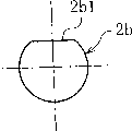
Be provided with for example planar surface portion 2b1 on the axial end portion of output shaft 2b, this shaft end is connected on the driven member of figure unshowned output terminal mechanism or device.The planar surface portion plane that forms on planar surface portion 2b1 by shaft end and the above-mentioned driven member is chimeric, and output shaft 2b and above-mentioned driven member interconnect and do not relatively rotate.Form two planar surface portion 2b1 on the relative position of 180 degree, perhaps shaft end processing is polygonal, it is also passable with the chimeric formation in plane each other that shaft end and above-mentioned driven member are a plurality of planes.The axle head of output shaft 2b is sealed by bottom 2b2.
The major diameter tube 2c of portion makes polygonal, octagon for example, and the periphery on each limit becomes camming surface 2c1 respectively.Thereby the periphery upper edge circumference of the major diameter tube 2c of portion has uniformly-spaced disposed eight camming surface 2c1.
Shown in Fig. 4 amplified, each the jut 2d with output terminal component 2 had with gap (gap delta 2 of sense of rotation shown in Figure 7) and is inserted in each through hole 1d of input end parts 1 on sense of rotation respectively.As shown in Figure 5, also can form boss 1d1 to each through hole 1d plunging processing.Therefore, can make jut 2d and through hole 1d chimeric reliably on sense of rotation.
On the outer side surface of the lip part 2a that lip part 3a is adorning at output terminal component 2, cylinder 3b becomes bearing (sliding bearing), is used for along the periphery of the output shaft 2b of radial direction rotatably support output terminal component 2.
Be provided with circumferential surface 3c1 on the interior week of major diameter tube 3c, the camming surface 2c1 relative radius direction of this circumferential surface 3c1 and output terminal component 2 has formed wedge gap on positive and negative two sense of rotation.
A plurality of (for example four) rectangular-shaped grooving 3d1 and a plurality of (for example four) circular-arc grooving 3d2 have uniformly-spaced been formed at blade of a sword portion 3d upper edge circumference.Grooving 3d1 cooperates with the connecting tendon 4c of fixed lateral plate 4 described later.Grooving 3d2 be for fear of with the bracket 4b that is installed in fixed lateral plate 4 on construction bolt disturb and be provided with.
As shown in Figures 1 and 2, fixed lateral plate 4 is mainly by the lip part 4a that extends along radial direction, outstanding a plurality of (for example four) bracket 4b from the outer circumferential face of lip part 4a towards the diameter lateral direction, from side-prominent a plurality of (for example four) connecting tendon 4c outer Zhou Dynasty axial one of lip part 4a, the cylinder 4d that extends continuously from axial the same side, the inner edge of lip part 4a (clutch internal direction) constitutes.
On the outer side surface of the lip part 1a that lip part 4a is adorning at input end parts 1.Four bracket 4b uniformly-spaced form along circumference, and form through hole 4b1 respectively.Scheming unshowned construction bolt inserts in this through hole 4b1.
Four connecting tendon 4c uniformly-spaced form along circumference, have a pair of pawl 4c1 (with reference to Fig. 2) that is divided into y-bend respectively.Connecting tendon 4c is embedded in the grooving 3d1 of Stationary side parts 3, a pair of pawl 4c1 is along the circumferential direction gone up opposite direction bending, tightly be associated on the 3d of blade of a sword portion of Stationary side parts 3.Therefore, Stationary side parts 3 and fixed lateral plate 4 axially and on the sense of rotation can not move each other.
As shown in Figure 2, disposed a pair of (for example the ading up to eight pairs) ball 6 as counterpart between the circumferential surface 3c1 of each the camming surface 2c1 of output terminal component 2 and Stationary side parts 3 respectively, these balls 6 are contained in the groove 1e between the column 1c of input end parts 1.The tongue piece 7b of elastic member 7 described later is inserted between a pair of ball 6, towards two balls direction pushing ball 6 separated from one another.Tongue piece 7b by camming surface 2c1, circumferential surface 3c1, a pair of ball 6 and elastic member 7 constitutes locking device, column 1c (cooperation important document) by the input end parts 1 on the circumferencial direction both sides that are positioned at a pair of ball 6 constitutes the latch-release device, constitutes torque transmitter by input end parts 1 through hole 1d and the projection 2d that inserts the output terminal component 2 in this through hole.In addition, the space between the interior week of the periphery of output terminal component 2 and Stationary side parts 3 is enclosed as lubricant grease between camming surface 2c1 and circumferential surface 3c1 etc. especially.
As shown in Figure 6, the elastic member 7 tongue piece 7b that possesses baseplate part 7a and extend to an axial side from baseplate part 7a.Elastic member 7 processing all-in-one-piece ring-types, on ring-type substrate 7a, how right tongue piece 7b is uniformly-spaced to dispose along circumference in pairs.Elastic member 7 is sheet metals, for example the stamping part of Steel Spring Plate.
In the present embodiment, the periphery of substrate 7a is an octagon, on each limit of periphery of substrate 7a a pair of tongue piece 7b is set respectively.A pair of tongue piece 7b is pasting each limit of periphery of substrate 7a and is being curved shape, connects substrate 7a through rising portions 7c respectively.Shown in Fig. 6 (c), a pair of tongue piece 7b is inserted between a pair of ball 6, with a pair of ball 6 towards making their direction elasticity separated from one another pushing.
Shown in the enlarged view of Fig. 7, on the neutral position, a pair of ball 6 be subjected to elastic member 7 tongue piece 7b pushing and have towards the trend that is separated from each other direction motion, just respectively and the wedge gap of positive and negative two sense of rotation that form between camming surface 2c1 and the circumferential surface 3c1 chimeric.At this moment, between each column 1c of input end parts 1 and each ball 6, there is sense of rotation gap delta 1 respectively.And between the through hole 1d of the projection 2d of output terminal component 2 and input end parts 1, on positive and negative two sense of rotation, also there is sense of rotation gap delta 2 respectively.The relation of sense of rotation gap delta 1 and δ 2 is δ 1<δ 2.The size of sense of rotation gap delta 1 can for as 0~0.4mm (be with the axle center of clutch center 0~1.5 °), and the size of sense of rotation gap delta 2 can be as 0.4~0.8mm (be with the axle center of clutch center 1.8~3.7 °) scope.
Under state shown in Figure 7, for example, if clockwise reverse input torque passes to output terminal component 2, then counterclockwise the ball 6 at (sense of rotation rear) is chimeric with the wedge gap of this direction, and output terminal component 2 is locked on the clockwise direction with respect to Stationary side parts 3.If anticlockwise reverse input torque passes to output terminal component 2, then the ball 6 of clockwise direction (sense of rotation rear) is chimeric with the wedge gap of this direction, on output terminal component 2 is locked to counterclockwise with respect to Stationary side parts 3.Thereby, under ball 6 effects, be locked on the positive and negative both direction from the reverse input torque of output terminal component 2.
After Fig. 8 illustrated input torque (with clockwise direction among the figure) and inputs to input end parts 1, input end parts 1 began the original state of rotating toward the clockwise direction in this figure.Because set sense of rotation gap delta 1<δ 2, so, at first, the column 1c of the counter clockwise direction of input end parts 1 (sense of rotation rear) engages with the ball of this direction (sense of rotation rear), and this ball 6 heads on elastic force (sense of rotation the place ahead) pushing toward the clockwise direction of tongue piece 7b.Therefore, counterclockwise the ball 6 at (sense of rotation rear) is deviate from from the wedge gap of this direction, has removed the lock state (in addition, the ball 6 of clockwise direction (sense of rotation the place ahead) does not engage with the wedge gap of this direction) of output terminal component 2.Thereby output terminal component 2 can rotate toward the clockwise direction.
When input end parts 1 rotated toward the clockwise direction again, as shown in Figure 9, the wall of the through hole 1d of input end parts 1 engaged in the clockwise direction with the projection 2d of output terminal component 2.Therefore, passed to output terminal component 2 from the clockwise input torque via through holes 1d of input end parts 1 and the mating part of projection 2d, output terminal component 2 rotates toward the clockwise direction.When input torque in the counterclockwise direction passes to input end parts 1, with above-mentioned opposite action under, output terminal component 2 is towards counterclockwise rotating.Thereby through being delivered to output terminal component 2 as the through hole 1d of torque transmitter and projection 2d, output terminal component 2 can rotate towards positive and negative two sense of rotation from the input torque of positive and negative two sense of rotation of input end parts 1.In addition, if disappear from the input torque of input end parts 1, then ball 6 and input end parts 1 are returned to neutral position shown in Figure 7 under the elastic restoring force effect of tongue piece 7b.
Figure 10~Figure 12 illustrates second embodiment of the invention.Second embodiment and above-mentioned first embodiment's difference is to adopt as torque transmitter the inserted structure of the projection 22d of grooving 21d and diameter extroversion.As shown in figure 12, grooving 21d is formed on the outer circumferential side of lip part 1a of input end parts 1.Grooving 21d has a plurality of (for example eight), uniformly-spaced disposes along circumference.It is big that the bottom 1c1 of column 1c along the circumferential direction slowly becomes, and grooving 21d is between the bottom 1c1 adjacent along circumference.Projection 22d outside the footpath is connected with the end of the large-diameter portion 2c of output terminal component 2 through axial bottom 22d1, has a plurality of (for example eight), uniformly-spaced disposes along circumference.Each projection 22d of output terminal component 2 is adaptive with each grooving 21d respectively, between the two gapped δ 2 (with reference to Fig. 7) on sense of rotation.
According to the present invention, can provide to have had following function, even pass to output terminal from the input torque of input end, and it is locked from the reverse input torque of output terminal, do not return, and reverse input compact, that amount is light, valency is low intercepts clutch to input end.
Figure 14 and Figure 15 illustrate the integral body of using above-mentioned reverse input to intercept the clutch device of clutch C (locking-typed) and constitute.This clutch device is motor M, speed reducer R, and the modular appliance after the reverse input obstruct clutch C modularization.This clutch device has the function of the device of rotation driving that driving torque takes place, wherein the torque that is produced by motor M is after speed reducer R slows down, and intercepts clutch C from the output shaft R1 of speed reducer R through reverse input and is input to the O of output terminal mechanism (with reference to Figure 17 and Figure 18).If mention the reflecting mirror drive unit of above-mentioned automobile, then be equivalent to the O of output terminal mechanism for the reflecting mirror of driven object (peephole etc.).
Oppositely input intercepts clutch C mainly by the input end parts 1 of the torque of accepting speed reducer R output, the output terminal component 2 of output torque, the Stationary side parts 3 that restriction is rotated, be fixed on the fixed lateral plate 4 on the Stationary side parts 3, locking device described later, latch-release device and torque transmitter constitute.
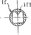
The output terminal R1 of speed reducer R is inserted into the interior week of joint 1f of input end parts 1.The front end periphery of output shaft R1 is processed into the polygonal corresponding with the interior week of joint 1f, and for example quadrilateral forms four planar surface portion by tetragonal each limit.Each the planar surface portion 1f1 that is formed on each planar surface portion on the output shaft R1 and joint 1f is after chimeric each other, and both interconnect output shaft R1 and input end parts 1 but can not relatively rotate.
The output shaft 2b of output terminal component 2 is connected on the driven member (omitting among the figure) of the O of output terminal mechanism.For present embodiment, though show the situation that the shaft end of output shaft 2b is processed into barrel surface, also can be the same with embodiment shown in Figure 1, this axle head is processed one or more plane 2b1.Construction bolt in the through hole 4b1 that inserts fixed lateral plate 4 is installed on the parts (support, shell etc.) of speed reducer R side, just can intercepts clutch C to reverse input and directly be fixed on the speed reducer R.The means that reverse input obstruct clutch C is fixed on the speed reducer R are not limited to use bolt, can select arbitrarily.Also can intercept clutch C to reverse input is fixed on the motor of band speed reducer as motor M and speed reducer R external member on sale on the market.
Oppositely input obstruct clutch C formation and work in addition is standard in order to Fig. 1~embodiment shown in Figure 13, therefore, omits repeat specification.
In the above description, as shown in figure 16, in rotating driving system by the torque actuated output terminal O of mechanism of motor M, though show motor M, speed reducer R and the reverse clutch device (being shown in broken lines components) that intercepts after clutch C makes assembly of importing, as shown in figure 17, also can intercept clutch C to reverse input and from speed reducer R, separate,, constitute the clutch device of accepting torque and moving with the O of output terminal mechanism constituent components.The structure that the reverse input of this moment intercepts clutch C possesses the structure for the clutch device of base description according to Fig. 1~Figure 15.In the case, the joint 1f of input end parts 1 is connected with the transmission shaft 10 that the output terminal from speed reducer R stretches out, and the output shaft 2b of output terminal component 2 connects the input end (driven member) of the output terminal O of mechanism.
Above-mentioned reverse input intercepts the reflecting mirror drive unit that clutch C is not limited to automobile, can also use on various mechanisms or device.For example, change the oscillator device (joint portion of bed, seat, robot etc.) of angle, change the lowering or hoisting gear (Window Glass of lift, shutter, jack, automobile etc.) of rectilinear direction, switch gear (door, shutter, roof transom window, power-operated sliding door etc.), slewing gear (trailing wheel of electric-powered Effector, automobile sprocket tooth, electronic chair, electric bicycle, four-wheel drive [the ball spring] etc.).Specifically, for example, the feed screw of operation mechanism or control gear, monitoring bed or the family that is driven by snap bolt is with in the feed screw of lift etc., oppositely import obstruct clutch C by configuration between these screw mandrels and motor, with respect to the reverse input torque from screw (driven member that is equivalent to the O of output terminal mechanism), output terminal component 2 is locked, has prevented that reverse input torque from passing to motor side.
Instrument for electric drive etc., if the above-mentioned reverse input of configuration intercepts clutch C between motor and chuck, then with respect to the reverse input torque that applies from chuck, because output terminal component is locked, so behind the electric tightening screw, further tighten (rotation body) with hand again, then can improve the mechanical property of this instrument.
For electrically propelled chair or the motorized window that automobile is used, also can disposing oppositely between motor and chair (or window), input intercepts clutch C.In these mechanisms, what speed reducer used is worm and worm wheel mechanisms, and in most cases this structure can not make the reverse input torque from chair or window pass to motor side, but because the transmission of torque efficient of worm gear and worm screw is extremely low, must increase the capacity of motor, this is a shortcoming.For this reason, input intercepts clutch C if use oppositely, then owing to the reverse input torque passback that can prevent from chair, therefore, can use the high horizontal gear of transmission efficiency to wait and replace worm gear and worm screw as speed reducer, and realize the miniaturization of capacity motor.
Also can intercept clutch C to above-mentioned reverse input is configured in the rotating drive portion of C arm of X ray checking device.The C arm is the C word shape parts that x-ray irradiation device and light receiver are set, and in the inspection, the C arm is rotated around the body that is taken, and takes at an arbitrary position.Be configured between this arm and the motor by above-mentioned reverse input is intercepted clutch C, just can suppress the C arm and wave, improve and take precision.
For example, for motorcycle (バ ィ Network), wheelbarrow, the vehicle of tractor etc., uneven road surface applies spring-back force to operating handle under steam.At this moment,, then can suppress to add elastic force, improve the Security of handling if the above-mentioned reverse input of configuration intercepts clutch C between control lever shaft and axletree.
According to the present invention, because the source of rotational drive that is made of motor and speed reducer is become modularization with clutch (perhaps clutch and output terminal mechanism), so can improve the lightweight clutch device of compact structure.Because this clutch device has the input torque of input end is passed to output terminal, lock the function that does not pass to input end from the reverse input torque of output terminal, therefore,, can in source of rotational drive, not rotate even produce reverse input torque yet.Thereby, can avoid excessive reverse input torque that speed reducer and motor are produced and have a strong impact on, can also become and be very suitable for utilizing reverse input torque to make the device of the shift in position of output terminal mechanism.
Below, the clutch device that uses clutch (free type) is described, wherein this clutch is to make output terminal component idle running for reverse input torque, intercepts that this torque transmits to input end.
Figure 18 illustrates an embodiment of this kind clutch device.As shown in the figure, this clutch device intercepts clutch C by reverse input, limiting part 20, and constitute as the motor M of source of rotational drive.The reverse input obstruct of the torque warp clutch C of motor M output passes to the reflecting mirror 30 as driven member, and making reflecting mirror 30 is that wave towards positive and negative direction at the center with rotatingshaft P.Limiting part 20 remains on reflecting mirror 30 on predetermined accommodated position and the use position.
As Figure 19 and shown in Figure 20, oppositely input obstruct clutch C possesses the input outer ring 11 as the input end parts, output inner ring 12 as output terminal component, roller 13 as torque transmission member, the retainer 14 that keeps roller 13, positioning retainer 14 positions and as the central annular spring 15 of first elastic member, the first and second side plate 16a, 16b as the Stationary side parts, and, the conduct of the level and smooth surface friction drag of retainer effect is provided the sliding spring 17 of rotational resistance device with respect to the rotation of retainer 14.The input torque of motor M output is delivered on the input outer ring 11, and exports from output inner ring 12 through roller 13.As shown in Figure 1, the rotatingshaft of reflecting mirror 30 is connected to output inner ring 12.
Below, for ease of explanation, the figure right side of face of Figure 19 is called one distolateral, call the drawing left side distolateral in addition.
On a distolateral periphery of input outer ring 11, form tooth 11b.As shown in figure 19, constitute reducing gear R because of tooth 11b with actuation gear 5 engagements that are installed on the output shaft of motor M.Reducing gear R is not limited to illustrated formation, can adopt arbitrarily to constitute.On the periphery of the input outer ring 11 that tooth 11b constitutes except the metallic material that is formed directly into by Chilled Hardened Steel etc., can also be formed on the other parts, and it is fixed on the periphery of input outer ring 11.At this moment, for example can consider, with resin system tooth 11b, with metallic material systems such as Chilled Hardened Steel inputs outer ring 11, be pressed into, concavo-convex chimeric or insert means formation one such as shaping.
As shown in figure 21, in an end of input outer ring 11, formed to the side-prominent 11c of blade of a sword portion of internal diameter on week.On position of circumferencial direction of the 11c of this blade of a sword portion, form grooving 11d across its entire axial length.
As Figure 19 and shown in Figure 20, output inner ring 12 is configured in the internal side diameter of input outer ring 11.This output inner ring 12 possesses facing to the cylindrical body 12a of the inner peripheral surface of input outer ring 11 with towards axially extended axial region 12b.In the present embodiment, the periphery of cylindrical body 12a is cylindric.
As shown in figure 22, on the inner peripheral surface of input outer ring 11, with the outer circumferential face of cylindrical body 12a of output inner ring 12 between along the circumferential direction uniformly-spaced form a plurality of (identical) camming surface 11a with the quantity of roller 13, camming surface 11a constitutes and is symmetrical in the wedge gap s1 that positive and negative two sense of rotation are slowly dwindled.Wedge gap s1 is a following gap, and c1 is bigger than the diameter of roller 13 in circumferencial direction central authorities, and dwindles symmetrically to positive and negative two sense of rotation from the c1 of circumferencial direction central authorities.When roller 13 was positioned on the circumferencial direction central authorities c1 position of wedge gap s1, roller 13 can freely rotate in wedge gap s1.
As shown in figure 24, location annular spring 15 is to be made of the leaf spring that is bent into U-shaped.This location annular spring 15 is as Figure 19 and shown in Figure 20, in advance the phase place of the circumferencial direction of the grooving 14b of the grooving 11d of input outer ring 11 and retainer 14 is coincide, the hypertonic direction that makes the U-shaped two ends again is towards circumferencial direction, and allow U-shaped bottom 15a be positioned at the depths, then, chimeric with two grooving 11d, 14b.This location annular spring 15 has two effects, an effect is that elasticity connects retainer 14 and input outer ring 11 on sense of rotation, the 2nd, determine the position (positioning action) of retainer 14, so that be contained in the circumferencial direction central authorities c1 place that the interior roller 13 of pod 14a of retainer 14 is positioned at wedge gap s1 with respect to input outer ring 11.Figure 22 illustrates the state by retaining spring 15 positioning retainers 14, under this state, the circumferencial direction center of the pod 14a of retainer 14 is consistent with the circumferencial direction center of the camming surface 11a of input outer ring 11, and roller 13 is positioned at the circumferencial direction central authorities c1 place of wedge gap s1.
The first side plate 16a and the second side plate 16b are the parts (non-rotatable member) that belong to stationary system, form with sheet metal stamping part or resin forming product.As shown in figure 19, under the state that has held each constitutive requirements of clutch (input outer ring 11, output inner ring 12, roller 13, retainer 14, retaining spring 15, sliding springs 17) between biside plate 16a, the 16b, they are linked into an integrated entity with fixing devices such as bolts.
Formed cylindrical shell 16a1 and bear the 16a2 of portion on the first side plate 16a, cylindrical shell 16a1 inside holds his end and sliding spring 17 of retainer 14, and the portion 16a2 of bearing is the parts that extend to internal side diameter from his end of cylindrical shell 16a1.Bear the 16a2 of portion at the cylindrical shell 12a end face that axially faces toward output inner ring 12, the inner side surface that bears the 16a2 of portion is pressed on the end face of cylindrical shell 12a.Having formed inside on the second side plate 16b holds the cylindrical shell 16b1 that imports outer ring 11 and is configured in its inner 16b2 of support part.In the interior week that the axle 12b of output inner ring 12 inserts the 16b2 of support part, the 16b2 of this support part supporting axle 12b radially rotates, thereby has played the effect of bearing (sliding bearing).The part of the cylindrical body 16b1 of the second side plate 16b is cut off, on this cut-out, and the tooth 11b of input outer ring 11 and actuation gear shown in Figure 15 engagements.
Sliding spring 17 is the parts that slide with respect to the first side plate 16a, in the present embodiment, and with there being end ring shape spring material to form.As shown in figure 25, this sliding spring 17 possesses the annulus 17a and the auxiliary section 17b, the 17c that make the inward at both ends lateral buckling of slide part 17a of slip.Be pressed in the cylindrical body 16a1 of the first side plate 16a after slide part 17a slightly inwardly shrinks, flexibly closely contact with cylindrical body 16a1 inner peripheral surface.In any case auxiliary section 17b, 17c insert in the grooving 14c of his distolateral circumferencial direction of retainer, the distance of the circumferencial direction between auxiliary section 17b, the 17c is shorter than the circumferencial direction length of grooving 14c.
Below, illustrate that oppositely input intercepts the action of clutch C.
A-stage before torque is input to input outer ring 11, as shown in figure 22, retainer 14 is subjected to retaining spring 15 effects and is positioned.Thereby the interior roller 13 of pod 14a that is contained in retainer 14 is positioned on the c1 of circumferencial direction central authorities of wedge gap s1 between camming surface 11a that imports outer ring 11 and the cylindrical body 12a that exports inner ring 12.
When clockwise torque among the figure was input on the input outer ring 11 from motor M, the retainer 14 that connects input outer ring 11 by retaining spring 15 began to rotate with input outer ring 11.When retainer 14 turned to several angle, as shown in figure 25, the end face 14d of sense of rotation rear side of the grooving 14c of boundary retainer 14 became the auxiliary section 17c state of contact with the sense of rotation rear side of sliding spring 17.
When input outer ring 11 when rotating again, under the end face 14d of retainer 14 and the chimeric state of the auxiliary section 17c of sliding spring 17, sliding spring 17 will be with moving.At this moment, sliding spring 17 slides in the cylindrical body 16a1 of the first side plate 16a, bears smooth surface friction drag from Stationary side.The smooth surface friction drag of this moment is delivered to retainer 14 through auxiliary section 17c, becomes the rotational resistance of retainer 14.Therefore, if preestablish the elastic force (spring torque) of the rotational resistance (torque) of the retainer 14 that the smooth surface friction drag because of slide part 17 causes greater than retaining spring 15, retaining spring 15 will resiliently deformable, therefore distortion, and retainer 14 is slack-off with respect to the rotation of input outer ring 11.
Because the rotation of retainer 14 is slack-off, as shown in figure 26, become the state of the wedge gap s1 between the outer circumferential face that meshes camming surface 11a that imports outer ring 11 and the cylindrical body 12a that exports inner ring 12 by the roller 13 of pod 14a maintenance.Therefore, the torque that is input on the input outer ring 11 passes to output inner ring 12 through roller 13.When torque was input on the input outer ring 11 counterclockwise, output inner ring 12 was to rotate towards counter clockwise direction with above-mentioned opposite action.
When input outer ring 11 stopped, because of the recuperability effect of retaining spring 15, roller 13 was deviate from from wedge gap s1, was positioned in the c1 of circumferencial direction central authorities of wedge gap s1.Increase at the engaging force (residual torque) that acts on the roller 13, after input outer ring 11 stops, when roller 13 still meshes with wedge gap s1, by apply the torque of (opposite) counterclockwise (by making 11 counter-rotatings of input outer ring) to input outer ring 11, roller 13 is deviate from from wedge gap s1 with the direction of input torque.
On the other hand, from reflecting mirror 30 to output inner ring 12 when having applied reverse input torque because the smooth surface friction drag of sliding spring 17 can not produce, therefore, under the effect of retaining spring 15, retainer 14 remains under the positioning states (with reference to Figure 22).Under this positioning states, because roller 13 is positioned at the circumferencial direction central authorities of wedge gap s1, roller 13 is free to rotate.From the above, make 12 idle running of output inner ring, can intercept reverse input torque and pass to input end.
Therefore restricting means 20 can remain on reflecting mirror 30 on accommodated position and the use position because concavity auxiliary section 21 and convex auxiliary section 22 springs on another on any one in Stationary side parts or the output inner ring 12 are chimeric.
In Figure 19, exemplary represented respectively forms convex auxiliary section 22 forming on the 16a2 of the portion of bearing as the first side plate 16a of Stationary side parts on concavity auxiliary section 21, the cylindrical body 12a at output inner ring 12 on the other side.The concavity auxiliary section 21 for example inner side surface of the 16a2 of the portion of bearing by the first side plate 16a that subsides forms, and it forms position is that 90 ° of circumferencial direction dislocation are equally spaced everywhere (with reference to Figure 27 a).Convex auxiliary section 22 for example forms with steel ball, in second spring members 24 of helical spring class is contained in axial bore 23 on the cylindrical body 12a end face of output inner ring 12.In the present embodiment, convex auxiliary section 22 and the 21 the same formation of concavity auxiliary section misplace in a circumferential direction 90 ° everywhere equally spaced.The elastic force effect that convex auxiliary section 22 is subjected to elastic member 24 is pressed on the end face that bears the 16a2 of portion for a long time, and each concavity auxiliary section 21 is configured on the rotary motion trace of this convex auxiliary section 22.Thereby slide on the inner side surface that bears the 16a2 of portion along with the rotation of output inner ring 12 or rotate in convex auxiliary section 22, outstanding because of facing concavity auxiliary section 21, can flexibly cooperate with concavity auxiliary section 21.
According to above formation, at reflecting mirror 30 when accommodated position is opened to the use position, perhaps when the use position is closed into accommodated position, reflecting mirror 30 will rotate 90 ° basically, because concavity auxiliary section 21 and convex auxiliary section 22 elasticity are chimeric, so reflecting mirror 30 can be remained on everywhere on the position.Because being connected to, reflecting mirror 30 make output inner ring 12 intercept clutch C as mentioned above like that with respect to the reverse input of reverse input torque idle running, even so body oscillating or travel in blast reflecting mirror 30 is rotated, and cause its dislocation, because of clutch device of the present invention has above-mentioned restricting means 20, so can offset external force, reflecting mirror 30 positively is fixed on each assigned position.
When concavity auxiliary section 21 in the driving in motor M and convex auxiliary section 22 are relative, convex auxiliary section 22 drops in the concavity auxiliary section 21, because of two chimeric rotational angle are determined, at this moment, because torque suspension increases influence, the driving current of motor M increases, increase because of detecting electric current, then, detect reflecting mirror 30 and arrive accommodated position or use position, and, motor is stopped according to this signal.Thereby, can provide the rotational angle feeler mechanism with sensor needn't be set in addition, just can detect rotational angle, and structure is compact, the electronic stored type reflecting mirror that cost is low.
After reflecting mirror 30 touches pedestrian or obstacle, when big reverse input torque affacted on the output inner ring 12 as surpassing the spring slip torque of second elastic member 24, convex auxiliary section 22 ran off the step of concavity auxiliary section 21 and deviates from from concavity auxiliary section 21.After deviating from, 12 idle running of output inner ring, and absorb external force, therefore, can avoid reflecting mirror 30 damages.At this moment, because oppositely input torque can not pass on motor M and the reducing gear R etc., therefore, can prevent that these mechanisms are impaired.
Except as mentioned above, the inner side surface local collapse is formed outside the concavity auxiliary section 21, can also constitute concavity auxiliary section 21 in the mode that on inner side surface, forms circular protrusion 26a as shown in figure 27.At this moment, because the increase of motor current value beginning before two auxiliary sections 21,22 are chimeric stops motor by surpass the moment that begins to reduce behind the peak value at current value, just can positively make 21,22 cooperations of two auxiliary sections.Figure 28 illustrates by the sense of rotation with convex auxiliary section 21 and is vertically formed the example that two row straight line shape projection 26b constitute concavity auxiliary section 21.
In the present embodiment, though concavity auxiliary section 21 is located on the first side plate 16a into Stationary side, convex auxiliary section 22 is located on the output inner ring 12 into turn side, but also can be in contrast, concavity auxiliary section 21 is located on the turn side parts (for example exporting inner ring 12), convex auxiliary section 22 is located on the Stationary side parts (for example first side plate 16a).Though concavity auxiliary section 21 and convex auxiliary section 22 have all formed four, if either party is 90 ° two of being separated by, then the opposing party forms just passable at least on a position.
For above explanation, illustrated that exemplarily driven member is the electric sealed reflecting mirror of automobile, but, then any parts can have been used as driven member if can position driven member two above positions.For example, can consider between two positions, to carry out the switch gear (door, shutter, roof transom window, power-operated sliding door) of switch motion.The qualification position of location driven member is not limited to two, also can be more than three.At this moment, necessary increase and decrease is also done corresponding to the position location in the cooperation place of concavity auxiliary section 21 and convex auxiliary section 22.
As mentioned above, according to the present invention, utilize oppositely input obstruct clutch, the input torque of the driving source of autorotation in the future passes to driven member, on the other hand, the reverse input torque that is applied on the output terminal component can be avoided passing to the input end parts.Thereby input end (motor, speed reducer etc.) can not be subjected to make reverse direction actuation from the reverse input torque of output terminal component, can avoid the damage of these parts.Reverse input torque so hour can remain on driven member on the assigned position, and when oppositely input torque is big, make output terminal component idle running, absorbs the impact that external force applies, and therefore, also can avoid the damage of driven members such as reflecting mirror.
In addition, when in fact using on electric sealed reflecting mirror, need following control to the mechanism of above-mentioned communique (spy opens flat 11-51092 number) record, promptly detect the rotational angle of reflecting mirror earlier, after detecting reflecting mirror arrival use position or accommodated position, motor is stopped.Therefore, sensor that detects rotational angle and the control system of handling the signal of this sensor need be set in addition, cause complex structure, and the present invention utilize the elastic force of restricting means to finish these work, therefore can not produce such problem.
Claims (22)
1. oppositely import the obstruct clutch for one kind, this clutch possesses the input end parts of input torque, the output terminal component of output torque, the Stationary side parts that restriction is rotated, be arranged between Stationary side parts and the output terminal component, for reverse input torque from output terminal component, the locking device of locking output terminal component and Stationary side parts, be arranged on the input end parts, for input torque from the input end parts, releasing is by the latch-release device of the lock state of locking device realization, be arranged between input end parts and the output terminal component, when having removed the lock state of locking device enforcement, input torque from the input end parts is passed to the torque transmitter of output terminal component, it is characterized in that:
Described latch-release device is made of the column that extends vertically of being located at the input end parts; Described torque transmitter is made of with the grooving portion or the hole portion that are located at the input end parts the jut of being located at output terminal component;
In described input end parts, output terminal component and the Stationary side parts, the input end parts are the punch process part of sheet metal at least.
2. reverse input according to claim 1 intercepts clutch, it is characterized in that, the joint that connects input shaft is located on the input end parts, and makes this connection part in clutch inside.
3. reverse input according to claim 2 intercepts clutch, it is characterized in that, above-mentioned joint is arranged in the input end parts all sides continuously on the cylindrical portion that the clutch internal direction is extended.
4. intercept clutch according to claim 2 or 3 described reverse inputs, it is characterized in that setting is at least one chimeric planar surface portion of plane with input shaft on the above-mentioned joint.
5. reverse input according to claim 1 intercepts clutch, it is characterized in that, tubular output shaft and above-mentioned output terminal component are provided with integratedly.
6. reverse input according to claim 5 intercepts clutch, it is characterized in that, above-mentioned output shaft one end sealing.
7. intercept clutch according to claim 5 or 6 described reverse inputs, it is characterized in that, at least one the chimeric planar surface portion of driven member plane with other is set on output shaft.
8. reverse input according to claim 1 intercepts clutch, it is characterized in that, above-mentioned locking device possesses the circumferential surface that is arranged on the Stationary side parts, be arranged on the output terminal component, and form the camming surface of wedge gap between the circumferential surface in positive and negative two sense of rotation, a pair of counterpart between camming surface and circumferential surface, and the elastic member that pushes a pair of counterpart respectively to the wedge gap direction, the latch-release device be with a pair of counterpart in any one select a ground and cooperate, towards pushing the important document that cooperates of this counterpart with the opposite direction of wedge gap direction, torque transmitter is arranged on the cooperation important document of the sense of rotation on input end parts and the output terminal component, and, on the neutral position of latch-release device and torque transmitter, on sense of rotation, there is gap delta 1 between described latch-release device and the counterpart, on sense of rotation, have gap delta 2 between the cooperation important document of torque transmitter, and the relation of two gap delta 1 and δ 2 is δ 1<δ 2.
9. reverse input according to claim 8 intercepts clutch, it is characterized in that, above-mentioned jut is outstanding along the external diameter direction.
10. reverse input according to claim 8 intercepts clutch, it is characterized in that, above-mentioned jut is outstanding vertically.
11. reverse input according to claim 8 intercepts clutch, it is characterized in that, the tongue piece that above-mentioned elastic member possesses the bottom and extends to an axial side from this bottom, tongue piece is between a pair of counterpart, and the formation of tongue piece can be a pair of counterpart towards the direction pushing that they are separated from each other.
12. reverse input according to claim 11 intercepts clutch, it is characterized in that above-mentioned bottom is a ring-type, above-mentioned tongue piece is a plurality of along the circumference configuration.
13. reverse input according to claim 8 intercepts clutch, it is characterized in that above-mentioned counterpart is a roller.
14. reverse input according to claim 1 intercepts clutch, it is characterized in that also possessing the fixed lateral plate that is fixed on the Stationary side parts, the said fixing side plate adopts the plastically worked article of sheet metal.
15. reverse input according to claim 14 intercepts clutch, it is characterized in that the said fixing side plate has the bearing of radial support input shaft.
16. reverse input according to claim 15 intercepts clutch, it is characterized in that, above-mentioned bearing is arranged on interior all sides from fixed lateral plate continuously on the cylinder that the clutch internal direction is extended.
17. clutch device, it is characterized in that, this clutch device is source of rotational drive and oppositely imports the incorporated device of obstruct clutch pack, above-mentioned reverse input intercepts clutch to be possessed: input is from the input end parts of the torque of source of rotational drive, the output terminal component of output torque, the Stationary side parts that restriction is rotated, be arranged between Stationary side parts and the output terminal component, for the locking device that locks output terminal component and Stationary side parts from the reverse input torque of output terminal component, be arranged on the input end parts, for the latch-release device of removing the lock state of realizing by locking device from the input torque of input end parts, when having removed the lock state of locking device enforcement, the input torque from the input end parts is passed to the torque transmitter of output terminal component;
Described latch-release device is made of the column that extends vertically of being located at the input end parts; Described torque transmitter is made of with the grooving portion or the hole portion that are located at the input end parts the jut of being located at output terminal component;
In described input end parts, output terminal component and the Stationary side parts, the input end parts are the punch process part of sheet metal at least.
18. clutch device, it is characterized in that, this clutch device is output terminal mechanism and oppositely imports the incorporated device of obstruct clutch pack, above-mentioned output terminal mechanism carries out compulsory exercise by passing to the torque that reverse input intercepts the output terminal component of clutch, above-mentioned reverse input intercepts clutch, possess: input is from the input end parts of the torque of source of rotational drive, the output terminal component of output torque, the Stationary side parts that restriction is rotated, be arranged between Stationary side parts and the output terminal component, for the locking device that locks output terminal component and Stationary side parts from the reverse input torque of output terminal component, be arranged on the input end parts, for the latch-release device of removing the lock state of realizing by locking device from the input torque of input end parts, when having removed the lock state of locking device enforcement, the input torque from the input end parts is passed to the torque transmitter of output terminal component;
Described latch-release device is made of the column that extends vertically of being located at the input end parts; Described torque transmitter is made of with the grooving portion or the hole portion that are located at the input end parts the jut of being located at output terminal component;
In described input end parts, output terminal component and the Stationary side parts, the input end parts are the punch process part of sheet metal at least.
19., it is characterized in that oppositely input intercepts the input end parts of clutch, have the joint of the output shaft that connects source of rotational drive, and this connection part is in clutch inside according to claim 17 or 18 described clutch device.
20. clutch device according to claim 19 is characterized in that, this joint is arranged in the input end parts all sides continuously on the cylindrical portion that the clutch internal direction is extended.
21. clutch device according to claim 19 is characterized in that, setting is at least one chimeric planar surface portion of plane with the output shaft of source of rotational drive on joint.
22. according to claim 17 or 18 described clutch device, it is characterized in that, oppositely the locking device of input obstruct clutch possesses the circumferential surface that is arranged on the Stationary side parts, be arranged on the output terminal component, and form the camming surface of wedge gap between the circumferential surface in positive and negative two sense of rotation, a pair of counterpart between camming surface and circumferential surface, and the elastic member that pushes a pair of counterpart respectively to the wedge gap direction, the latch-release device is to cooperate with in a pair of counterpart any one, towards pushing the important document that cooperates of this counterpart with the opposite direction of wedge gap direction, torque transmitter is arranged on the cooperation important document of the sense of rotation on input end parts and the output terminal component, and, on the neutral position of latch-release device and torque transmitter, on sense of rotation, there is gap delta 1 between described latch-release device and the counterpart, on sense of rotation, have gap delta 2 between the cooperation important document of torque transmitter, and the relation of two gap delta 1 and δ 2 is δ 1<δ 2.
Applications Claiming Priority (6)
| Application Number | Priority Date | Filing Date | Title |
|---|---|---|---|
| JP2001065239A JP4009429B2 (en) | 2001-03-08 | 2001-03-08 | Reverse input prevention clutch |
| JP65239/2001 | 2001-03-08 | ||
| JP242258/2001 | 2001-08-09 | ||
| JP242232/2001 | 2001-08-09 | ||
| JP2001242258A JP2003056602A (en) | 2001-08-09 | 2001-08-09 | Rotary drive device |
| JP2001242232A JP2003056596A (en) | 2001-08-09 | 2001-08-09 | Rotating device with clutch |
Publications (2)
| Publication Number | Publication Date |
|---|---|
| CN1374465A CN1374465A (en) | 2002-10-16 |
| CN1288360C true CN1288360C (en) | 2006-12-06 |
Family
ID=27346195
Family Applications (1)
| Application Number | Title | Priority Date | Filing Date |
|---|---|---|---|
| CNB021067767A Expired - Fee Related CN1288360C (en) | 2001-03-08 | 2002-03-08 | Clutch for cutting off reverse input and clutch arrangement with the same clutch |
Country Status (4)
| Country | Link |
|---|---|
| US (2) | US6695118B2 (en) |
| EP (2) | EP1239178B1 (en) |
| CN (1) | CN1288360C (en) |
| DE (2) | DE60215854T2 (en) |
Cited By (2)
| Publication number | Priority date | Publication date | Assignee | Title |
|---|---|---|---|---|
| CN100552250C (en) * | 2007-03-16 | 2009-10-21 | 蔡国法 | Overrunning clutch |
| CN104995122A (en) * | 2013-01-25 | 2015-10-21 | 三星重工业有限公司 | Trolley |
Families Citing this family (28)
| Publication number | Priority date | Publication date | Assignee | Title |
|---|---|---|---|---|
| WO2005108814A1 (en) * | 2004-05-06 | 2005-11-17 | Hans Heidolph Gmbh & Co. Kg | Anti-reactive modular gear unit and locking coupling |
| US7832542B2 (en) * | 2005-04-07 | 2010-11-16 | Donghwan Byun | Reverse input prevent clutch bearing assembly |
| DE102005023250B4 (en) * | 2005-04-28 | 2017-10-05 | Schaeffler Technologies AG & Co. KG | actuator |
| DE102005030719A1 (en) * | 2005-07-01 | 2007-01-04 | Schaeffler Kg | Silent ratchet for a seat adjusting device in a vehicle comprises a friction element in the form of an annular seal arranged in an annular groove of a drive element |
| KR100621347B1 (en) * | 2005-09-20 | 2006-09-07 | 주식회사 만도 | Electric power steering apparatus for automotive vehicle |
| US8181763B2 (en) * | 2006-01-31 | 2012-05-22 | Schaeffler Technologies AG & Co. KG | Window winder drive |
| FI118729B (en) | 2006-04-04 | 2008-02-29 | Kone Corp | Arrangement to stop a lift basket in an emergency and lift |
| KR100778560B1 (en) * | 2006-10-16 | 2007-11-22 | 현대자동차주식회사 | Deriving system and method of a side mirror |
| DE102007017617B4 (en) * | 2006-11-02 | 2016-06-09 | Johnson Controls Gmbh | Adjustment of a motor vehicle seat |
| US8448764B2 (en) * | 2007-12-12 | 2013-05-28 | Ntn Corporation | Rotation transmission device |
| JP5185209B2 (en) * | 2009-06-09 | 2013-04-17 | オリジン電気株式会社 | Reverse input cutoff clutch |
| US8950565B2 (en) | 2010-06-22 | 2015-02-10 | Rotork Controls Limited | Anti back-drive couplings |
| EP3998414B1 (en) * | 2010-07-16 | 2024-03-13 | Eltorque AS | Self lock mechanism |
| US8870692B2 (en) * | 2010-09-30 | 2014-10-28 | Shimano, Inc. | Bicycle derailleur with rotation resistance |
| US8852041B2 (en) | 2010-09-30 | 2014-10-07 | Shimano, Inc. | Bicycle derailleur with rotation resistance |
| DE102011084397A1 (en) * | 2011-10-13 | 2013-04-18 | Schaeffler Technologies AG & Co. KG | Freewheel for use as starter freewheel for starting of internal combustion engine, has two bearing races, where radial outer bearing race is divided in holding ring and bearing race part |
| NL1039622C2 (en) * | 2012-05-23 | 2013-11-26 | Forest Group Nederland Bv | FREE-COUPLING. |
| EP2698280B1 (en) * | 2012-08-14 | 2015-08-19 | Fico Mirrors, S.A. | Double detent folding mirror |
| JP6065505B2 (en) * | 2012-10-03 | 2017-01-25 | 株式会社ジェイテクト | Power generator |
| US9494202B2 (en) * | 2013-07-25 | 2016-11-15 | Toyota Jidosha Kabushiki Kaisha | Clutch |
| JP2015206455A (en) * | 2014-01-28 | 2015-11-19 | Ntn株式会社 | Reduction gear with brake |
| JP6157720B2 (en) * | 2014-03-14 | 2017-07-05 | オリジン電気株式会社 | Reverse input cutoff clutch |
| DE102014212863B4 (en) * | 2014-07-02 | 2020-08-20 | Stabilus Gmbh | Flap control |
| NL2018838B1 (en) * | 2017-05-03 | 2018-11-14 | Mci Mirror Controls Int Netherlands B V | Adjustment instrument and method |
| CN110848284A (en) * | 2018-08-20 | 2020-02-28 | 锅屋百泰株式会社 | Motor with reverse input blocking clutch and reverse input blocking clutch |
| WO2020133269A1 (en) * | 2018-12-28 | 2020-07-02 | 深圳配天智能技术研究院有限公司 | Limiting device, mechanical arm, and robot |
| US10711852B1 (en) * | 2019-01-18 | 2020-07-14 | General Electric Company | Locking clutch systems |
| CN112555293A (en) * | 2020-12-21 | 2021-03-26 | 上海探见智能家居有限公司 | Window opening clutch |
Family Cites Families (27)
| Publication number | Priority date | Publication date | Assignee | Title |
|---|---|---|---|---|
| US2260119A (en) * | 1940-06-28 | 1941-10-21 | Briggs Mfg Co | Clutch assembly |
| US2449020A (en) * | 1943-06-14 | 1948-09-07 | Automatic Locking Devices Inc | Power drive |
| US2561159A (en) * | 1944-09-14 | 1951-07-17 | Cecil E Walton | Self-locking clutch |
| US3011606A (en) * | 1957-07-26 | 1961-12-05 | Borg Warner | Roller clutch |
| US3005384A (en) * | 1960-08-17 | 1961-10-24 | Royal Engineering Co Inc | Power actuated rear view mirror |
| GB1174226A (en) * | 1968-01-17 | 1969-12-17 | Schaeffler Ohg Industriewerk | Improvements in Jamming-Roller Freewheel Clutches |
| US4070895A (en) * | 1975-09-20 | 1978-01-31 | Tokico Ltd. | Method for manufacturing bottom valve seat |
| US4676089A (en) * | 1985-05-13 | 1987-06-30 | Nevin Donald M | Hub for rotatable tool |
| GB2210941B (en) * | 1987-10-09 | 1991-11-13 | Ntn Toyo Bearing Co Ltd | Clutch |
| JPH01218729A (en) * | 1988-02-29 | 1989-08-31 | Sanden Corp | Manufacture of rotor main body for solenoid clutch |
| DE3839732A1 (en) * | 1988-11-24 | 1990-06-07 | Rentrop Hubbert & Wagner | BRAKE FOR AN ADJUSTMENT OF MOTOR VEHICLE SEATS |
| JPH0712509B2 (en) * | 1990-04-17 | 1995-02-15 | 日本精工株式会社 | Outside ring manufacturing method |
| DE9101110U1 (en) * | 1991-02-01 | 1992-02-27 | Schwarzbich, Joerg, 4800 Bielefeld, De | |
| JP2602999Y2 (en) * | 1991-12-26 | 2000-02-07 | 株式会社村上開明堂 | Electric retractable door mirror control device |
| EP0644084B1 (en) * | 1993-09-03 | 1998-05-20 | Ichikoh Industries Limited | Rearview mirror system for vehicles |
| DE9319848U1 (en) * | 1993-12-23 | 1995-01-26 | Schwarzbich Joerg | Seat adjustment |
| DE4447480A1 (en) | 1994-12-24 | 1996-06-27 | Schaeffler Waelzlager Kg | Clamping mechanism preferably provided for seat adjustment |
| US5703732A (en) * | 1995-01-17 | 1997-12-30 | Lowell Engineering Corporation | Exterior mirror with indexing and control pivoting |
| JP3516315B2 (en) | 1995-07-05 | 2004-04-05 | 本田技研工業株式会社 | Electric power steering device |
| EP0884494A1 (en) * | 1997-06-02 | 1998-12-16 | Ichikoh Industries Limited | Locking mechanism |
| FR2766773B1 (en) * | 1997-07-30 | 1999-10-15 | Faure Bertrand Equipements Sa | LOCKING DEVICE, PARTICULARLY FOR A MOTOR VEHICLE SEAT |
| DE29715257U1 (en) * | 1997-08-26 | 1997-12-04 | Atlas Copco Electric Tools | Driving device |
| US5952802A (en) * | 1997-12-08 | 1999-09-14 | Delco Electronics Corp. | Method of controlling an automotive mirror |
| DE19854945A1 (en) * | 1998-11-27 | 2000-05-31 | Schaeffler Waelzlager Ohg | Pinch roller switch mechanism |
| AUPP809399A0 (en) * | 1999-01-11 | 1999-02-04 | Britax Rainsfords Pty Ltd | A mirror rotation mechanism |
| US6267218B1 (en) * | 1999-03-12 | 2001-07-31 | INA Wälzlager Schaeffler oHG | Clamp-type locking mechanism |
| CA2325099C (en) * | 1999-11-04 | 2005-03-08 | Stant Manufacturing Inc. | Filler neck closure with static charge dissipator |
-
2002
- 2002-03-07 DE DE60215854T patent/DE60215854T2/en not_active Expired - Lifetime
- 2002-03-07 DE DE60202229T patent/DE60202229T2/en not_active Expired - Lifetime
- 2002-03-07 EP EP02251610A patent/EP1239178B1/en not_active Expired - Fee Related
- 2002-03-07 EP EP04076428A patent/EP1457700B1/en not_active Expired - Fee Related
- 2002-03-07 US US10/091,593 patent/US6695118B2/en not_active Expired - Lifetime
- 2002-03-08 CN CNB021067767A patent/CN1288360C/en not_active Expired - Fee Related
-
2003
- 2003-11-10 US US10/703,490 patent/US7117710B2/en not_active Expired - Lifetime
Cited By (2)
| Publication number | Priority date | Publication date | Assignee | Title |
|---|---|---|---|---|
| CN100552250C (en) * | 2007-03-16 | 2009-10-21 | 蔡国法 | Overrunning clutch |
| CN104995122A (en) * | 2013-01-25 | 2015-10-21 | 三星重工业有限公司 | Trolley |
Also Published As
| Publication number | Publication date |
|---|---|
| EP1239178A3 (en) | 2002-10-02 |
| DE60202229D1 (en) | 2005-01-20 |
| DE60215854T2 (en) | 2007-06-28 |
| US20040089049A1 (en) | 2004-05-13 |
| DE60215854D1 (en) | 2006-12-14 |
| EP1457700B1 (en) | 2006-11-02 |
| US7117710B2 (en) | 2006-10-10 |
| EP1457700A1 (en) | 2004-09-15 |
| CN1374465A (en) | 2002-10-16 |
| DE60202229T2 (en) | 2005-12-15 |
| EP1239178A2 (en) | 2002-09-11 |
| EP1239178B1 (en) | 2004-12-15 |
| US6695118B2 (en) | 2004-02-24 |
| US20020125099A1 (en) | 2002-09-12 |
Similar Documents
| Publication | Publication Date | Title |
|---|---|---|
| CN1288360C (en) | Clutch for cutting off reverse input and clutch arrangement with the same clutch | |
| JP5352465B2 (en) | Adjustment device, in particular for vehicle seats | |
| JP2019095070A (en) | Power transmission device | |
| CN1148303C (en) | Rotation mechanism of vehicle seats and seats arranged with rotation mechanism | |
| KR101313127B1 (en) | Fitting system for a vehicle seat | |
| JP5520945B2 (en) | Adjustment device, in particular vehicle seat adjustment device | |
| US8641146B2 (en) | Vehicle seat reclining apparatus | |
| CN1822476A (en) | Actuator device | |
| CN2851017Y (en) | Car gate rear view mirror for vehicle | |
| CN1723146A (en) | Electric power steering apparatus | |
| CN1702011A (en) | Electric steering lock apparatus | |
| CN1511093A (en) | Motor vehicle equipment module | |
| JP2013544147A (en) | Vehicle seat adjustment device with self-adjusting brake | |
| CN1796175A (en) | Recliner adjuster mechanism for a seat | |
| CN1055751C (en) | Clutch structure | |
| CN100575732C (en) | Locking plate and manufacture method thereof, overload clutch and toolroom machine | |
| CN1661255A (en) | Power transmitting apparatus | |
| CN1518925A (en) | Recliner adjuster for seat | |
| CN111577800A (en) | Parking brake device | |
| JP2005270298A (en) | Reclining device | |
| JP2008055565A (en) | Rotary table device | |
| CN1822922A (en) | Ratchet wrench and meethod of assembling the same | |
| CN1229584C (en) | Driving power transmission unit and driving device | |
| CN1853055A (en) | Friction clutch, in particular for motor vehicle, comprising multifunctional means | |
| JP2008112016A (en) | Lens drive device |
Legal Events
| Date | Code | Title | Description |
|---|---|---|---|
| C06 | Publication | ||
| PB01 | Publication | ||
| C10 | Entry into substantive examination | ||
| SE01 | Entry into force of request for substantive examination | ||
| C14 | Grant of patent or utility model | ||
| GR01 | Patent grant | ||
| CF01 | Termination of patent right due to non-payment of annual fee | ||
| CF01 | Termination of patent right due to non-payment of annual fee |
Granted publication date: 20061206 Termination date: 20200308 |