EP1239153A2 - Compressor coating - Google Patents
Compressor coating Download PDFInfo
- Publication number
- EP1239153A2 EP1239153A2 EP02003302A EP02003302A EP1239153A2 EP 1239153 A2 EP1239153 A2 EP 1239153A2 EP 02003302 A EP02003302 A EP 02003302A EP 02003302 A EP02003302 A EP 02003302A EP 1239153 A2 EP1239153 A2 EP 1239153A2
- Authority
- EP
- European Patent Office
- Prior art keywords
- swash plate
- slide contact
- lubricating
- based material
- piston
- Prior art date
- Legal status (The legal status is an assumption and is not a legal conclusion. Google has not performed a legal analysis and makes no representation as to the accuracy of the status listed.)
- Withdrawn
Links
- 239000011248 coating agent Substances 0.000 title 1
- 238000000576 coating method Methods 0.000 title 1
- 230000001050 lubricating effect Effects 0.000 claims abstract description 48
- 239000000463 material Substances 0.000 claims abstract description 29
- 239000010949 copper Substances 0.000 claims abstract description 28
- RYGMFSIKBFXOCR-UHFFFAOYSA-N Copper Chemical compound [Cu] RYGMFSIKBFXOCR-UHFFFAOYSA-N 0.000 claims abstract description 27
- 229910052802 copper Inorganic materials 0.000 claims abstract description 27
- 229910052797 bismuth Inorganic materials 0.000 claims abstract description 20
- JCXGWMGPZLAOME-UHFFFAOYSA-N bismuth atom Chemical compound [Bi] JCXGWMGPZLAOME-UHFFFAOYSA-N 0.000 claims abstract description 20
- 238000005245 sintering Methods 0.000 claims description 4
- 239000000956 alloy Substances 0.000 claims description 2
- 229910045601 alloy Inorganic materials 0.000 claims description 2
- KUNSUQLRTQLHQQ-UHFFFAOYSA-N copper tin Chemical compound [Cu].[Sn] KUNSUQLRTQLHQQ-UHFFFAOYSA-N 0.000 claims description 2
- 239000002826 coolant Substances 0.000 description 7
- XEEYBQQBJWHFJM-UHFFFAOYSA-N Iron Chemical compound [Fe] XEEYBQQBJWHFJM-UHFFFAOYSA-N 0.000 description 4
- 230000007423 decrease Effects 0.000 description 4
- 239000011347 resin Substances 0.000 description 4
- 229920005989 resin Polymers 0.000 description 4
- 230000008018 melting Effects 0.000 description 3
- 238000002844 melting Methods 0.000 description 3
- 229910000831 Steel Inorganic materials 0.000 description 2
- 238000006073 displacement reaction Methods 0.000 description 2
- 230000000694 effects Effects 0.000 description 2
- 229910052742 iron Inorganic materials 0.000 description 2
- 239000000314 lubricant Substances 0.000 description 2
- 239000002184 metal Substances 0.000 description 2
- 229910052751 metal Inorganic materials 0.000 description 2
- 239000000843 powder Substances 0.000 description 2
- 239000010959 steel Substances 0.000 description 2
- 206010027439 Metal poisoning Diseases 0.000 description 1
- ATJFFYVFTNAWJD-UHFFFAOYSA-N Tin Chemical compound [Sn] ATJFFYVFTNAWJD-UHFFFAOYSA-N 0.000 description 1
- 230000005183 environmental health Effects 0.000 description 1
- 208000008127 lead poisoning Diseases 0.000 description 1
- 239000007787 solid Substances 0.000 description 1
- 239000007921 spray Substances 0.000 description 1
Images

Classifications
-
- F—MECHANICAL ENGINEERING; LIGHTING; HEATING; WEAPONS; BLASTING
- F04—POSITIVE - DISPLACEMENT MACHINES FOR LIQUIDS; PUMPS FOR LIQUIDS OR ELASTIC FLUIDS
- F04B—POSITIVE-DISPLACEMENT MACHINES FOR LIQUIDS; PUMPS
- F04B27/00—Multi-cylinder pumps specially adapted for elastic fluids and characterised by number or arrangement of cylinders
- F04B27/08—Multi-cylinder pumps specially adapted for elastic fluids and characterised by number or arrangement of cylinders having cylinders coaxial with, or parallel or inclined to, main shaft axis
- F04B27/10—Multi-cylinder pumps specially adapted for elastic fluids and characterised by number or arrangement of cylinders having cylinders coaxial with, or parallel or inclined to, main shaft axis having stationary cylinders
- F04B27/1036—Component parts, details, e.g. sealings, lubrication
- F04B27/1054—Actuating elements
-
- F—MECHANICAL ENGINEERING; LIGHTING; HEATING; WEAPONS; BLASTING
- F04—POSITIVE - DISPLACEMENT MACHINES FOR LIQUIDS; PUMPS FOR LIQUIDS OR ELASTIC FLUIDS
- F04B—POSITIVE-DISPLACEMENT MACHINES FOR LIQUIDS; PUMPS
- F04B27/00—Multi-cylinder pumps specially adapted for elastic fluids and characterised by number or arrangement of cylinders
- F04B27/08—Multi-cylinder pumps specially adapted for elastic fluids and characterised by number or arrangement of cylinders having cylinders coaxial with, or parallel or inclined to, main shaft axis
- F04B27/0873—Component parts, e.g. sealings; Manufacturing or assembly thereof
- F04B27/0878—Pistons
- F04B27/0886—Piston shoes
-
- F—MECHANICAL ENGINEERING; LIGHTING; HEATING; WEAPONS; BLASTING
- F05—INDEXING SCHEMES RELATING TO ENGINES OR PUMPS IN VARIOUS SUBCLASSES OF CLASSES F01-F04
- F05C—INDEXING SCHEME RELATING TO MATERIALS, MATERIAL PROPERTIES OR MATERIAL CHARACTERISTICS FOR MACHINES, ENGINES OR PUMPS OTHER THAN NON-POSITIVE-DISPLACEMENT MACHINES OR ENGINES
- F05C2201/00—Metals
- F05C2201/04—Heavy metals
- F05C2201/0469—Other heavy metals
- F05C2201/0475—Copper or alloys thereof
-
- F—MECHANICAL ENGINEERING; LIGHTING; HEATING; WEAPONS; BLASTING
- F05—INDEXING SCHEMES RELATING TO ENGINES OR PUMPS IN VARIOUS SUBCLASSES OF CLASSES F01-F04
- F05C—INDEXING SCHEME RELATING TO MATERIALS, MATERIAL PROPERTIES OR MATERIAL CHARACTERISTICS FOR MACHINES, ENGINES OR PUMPS OTHER THAN NON-POSITIVE-DISPLACEMENT MACHINES OR ENGINES
- F05C2253/00—Other material characteristics; Treatment of material
- F05C2253/12—Coating
Definitions
- the present invention relates to a component having a lubricating surface formed therein in a compressor.
- a swash plate type compressor has pistons which reciprocatingly move upon rotation of a swash plate which rotates with a rotating shaft, as disclosed in the Japanese Unexamined Patent Publication No.59-231181, No.8-199327, No.9-209926 and No.10-153169.
- Shoes are disposed between the front end surface of the swash plate and the piston and between the back end surface of the swash plate and the piston, so that the rotational force of the swash plate is transferred to the pistons via the shoes.
- the shoes are made of an iron based material and make slide contact with the rotating swash plate, so the slide contact portion between the shoe and the swash plate may possibly abrade or sticking may occur between the shoe and the swash plate. For this reason, it is required to improve the slide contact characteristic of the swash plate to the shoe.
- the copper based material contains lead, having a low melting point, in the arts disclosed in the Japanese Unexamined Patent Publication No.59-231181 and No.10-153169.
- the lead contained in the copper based material is softened due to the high temperature caused by the friction between the swash plate and the shoes, and the softened lead appears on the slide contact surfaces between the swash plate and the shoes to increase lubricity of the slide contact surfaces.
- the present invention provides a component of a compressor, the component including a lubricating surface portion in a slide contact area, the lubricating surface portion being formed of a copper based material containing bismuth.
- the copper based material comprises copper-tin based alloy.
- the bismuth contained in the copper based material is metal having a low melting point like lead and has an identical function to lead. Because of the bismuth contained in the copper based material, the amount of lead to be used may be restricted.
- the copper based material does not contain lead.
- the amount of lead to be used is zero but a good lubricity may be obtained.
- a lubricating film made of a copper based material containing bismuth is provided in the slide contact area to form said lubricating surface portion.
- the lubricating film is made on a base material by sintering.
- the surface of the lubricating film made of the copper based material becomes the lubricating surface.
- the compressor comprises a swash plate type compressor having a swash plate rotatable with a rotating shaft, a piston, and a shoe disposed between the swash plate and the piston so as to make slide contact with the swash plate and the piston, whereby a rotational motion of the swash plate is transferred to the piston via the shoe to reciprocatingly move the piston and said component is the swash plate, in which the swash plate has a lubricating surface and the shoe has a lubricating surface to make slide contact with the lubricating surface of the swash plate.
- the slide contact area of the swash plate which makes slide contact with the shoe, is suitable for the area where a lubricating surface is formed.
- Fig.1A shows the internal structure of a variable displacement compressor.
- the rotating shaft 13 is supplied with a rotational drive force from an external driving source (e.g., vehicle engine).
- a rotating supporter 14 is fixed to the rotating shaft 13, and a swash plate 15 is supported by the rotating shaft 13 so as to be able to slide in the axial direction of the rotating shaft 13 and to tilt with respect to the axial direction.
- a supporter 151 is integrally formed with the swash plate 15 made of an iron based material, and guide pins 16 are fixed to the supporter 151.
- the guide pins 16 are slidably inserted in guide holes 141 which are formed in the rotating supporter 14.
- the swash plate 15 can tilt with respect to the axial direction of the rotating shaft 13 and rotate with the rotating shaft 13, by the linkage of the guide pins 16 with the guide holes 141.
- the tilting motion of the swash plate 15 is guided by the slide guide relation between the guide holes 141 and the guide pins 16 and the slidable support action of the rotating shaft 13.
- the angle of inclination of the swash plate 15 may be changed by controlling the pressure in the pressure control chamber 121. As the pressure in the pressure control chamber 121 increases, the angle of inclination of the swash plate 15 decreases, and as the pressure in the pressure control chamber 121 decreases, the angle of inclination of the swash plate increases.
- the coolant in the pressure control chamber 121 flows out to a suction chamber 191 in a rear housing 19 through a pressure discharge passage (not shown), and the coolant in a discharge chamber 192 in the rear housing 19 is introduced into the pressure control chamber 121 through a pressure supply passage (not shown).
- a capacity control valve 25 is disposed in the pressure supply passage, and the flow rate of the coolant supplied from the discharge chamber 192 to the pressure control chamber 121 is controlled by the capacity control valve 25.
- the capacity control valve 25 As the flow rate of the coolant supplied from the discharge chamber 192 to the pressure control chamber 121 increases, the pressure in the pressure control chamber 121 increases, and as the flow rate of the coolant supplied from the discharge chamber 192 to the pressure control chamber 121 decreases, the pressure in the pressure control chamber 121 decreases. That is, the angle of inclination of the swash plate 15 is controlled by the capacity control valve 25.
- the maximum angle of inclination of the swash plate 15 is defined as the angle at which the swash plate 15 is in abutment with the rotating supporter 14.
- the minimum angle of inclination of the swash plate 15 is defined as the angle at which the swash plate 15 is in contact with the circlip 24 on the rotating shaft 13.
- the cylinder block 11 has a plurality of cylinder bores 111 (only two are shown in Fig.1A) which are disposed around the rotating shaft 13. Each cylinder bore 111 accommodates a piston 17.
- the rotational motion of the swash plate 15 rotating with the rotating shaft 13 is converted into a longitudinal reciprocating motion of the pistons 17 via hemispherical shoes 18A and 18B, whereby the piston 17 moves forward and backward in the cylinder bore 111.
- the shoe 18A made of bearing steel makes slide contact with one lubricating surface of the swash plate 15, and the shoe 18B made of bearing steel makes slide contact with the other lubricating surface of the swash plate 15.
- the coolant in the suction chamber 191 flows into the cylinder bore 111 from a suction port 201 in a valve plate 20, pushing open a suction valve 211 on a valve forming plate 21.
- the coolant flowing into the cylinder bore 111 is then discharged, due to the forward motion (the motion from left to light in Fig.1A) of the piston 17, into the discharge chamber 192 from a discharge port 202 in the valve plate 20, pushing open a discharge valve 221 on a valve forming plate 22.
- the opening of the discharge valve 221 is limited by a retainer 231 on a retainer forming plate 23.
- lubricating films 28 and 29 are formed on the end surfaces 26 and 27 of the swash plate 15, respectively, which are slide contact areas.
- the lubricating films 28 and 29 are thermal spray layers of a copper (Cu) based material which includes copper as a main component.
- Surfaces of the lubricating films 28 and 29 are lubricating surfaces 281 and 291 which make slide contact with the shoes 18A and 18B, respectively.
- Table 1 shows the weight percentages of the components of the lubricating films 28 and 29. Three examples are shown in Table 1. In all examples, bismuth (Bi) is contained as a component of the copper based material. No. Cu Sn Zn Bi Sb P Ni 1 85.77 11.5 0.1 0.8 0.08 0.15 1.5 2 84.49 10.3 2.5 1.5 1.2 0.01 - 3 84.42 4.5 7.2 3.1 0.6 0.08 0.1
- the second embodiment shown in Fig.2 and the third embodiment shown in Fig.3 are also conceivable.
- lubricating films 30 and 31 made of resin are provided on the surfaces of the lubricating films 28 and 29 made of metal, respectively.
- solid lubricant is scattered in the resin. Provision of the lubricating films 30 and 31 made of resin is effective upon the slide contact in the non-lubricant condition.
- the swash plate 15A itself is made of a copper based material which contains bismuth but does not contain lead.
- the end surfaces 26 and 27 of the swash plate 15A themselves are lubricating surfaces.
- bismuth is contained in a copper based material for forming a lubricating surface portion in the slide contact area in a component of a compressor, and thereby good effect may be obtained that slide contact characteristic is good while restricting the amount of lead to be used.
Landscapes
- Engineering & Computer Science (AREA)
- Mechanical Engineering (AREA)
- General Engineering & Computer Science (AREA)
- Manufacturing & Machinery (AREA)
- Compressors, Vaccum Pumps And Other Relevant Systems (AREA)
- Compressor (AREA)
- Powder Metallurgy (AREA)
- Coating By Spraying Or Casting (AREA)
- Other Surface Treatments For Metallic Materials (AREA)
- Sliding-Contact Bearings (AREA)
Abstract
Lubricating films are formed on end surfaces of a
swash plate, respectively. The lubricating films make
slide contact with shoes, respectively. The lubricating
films are made of a copper based material which contains
bismuth but does not contain lead. A good slide contact
characteristic may be obtained while restricting the
amount of lead to be used.
Description
- The present invention relates to a component having a lubricating surface formed therein in a compressor.
- A swash plate type compressor has pistons which reciprocatingly move upon rotation of a swash plate which rotates with a rotating shaft, as disclosed in the Japanese Unexamined Patent Publication No.59-231181, No.8-199327, No.9-209926 and No.10-153169. Shoes are disposed between the front end surface of the swash plate and the piston and between the back end surface of the swash plate and the piston, so that the rotational force of the swash plate is transferred to the pistons via the shoes. The shoes are made of an iron based material and make slide contact with the rotating swash plate, so the slide contact portion between the shoe and the swash plate may possibly abrade or sticking may occur between the shoe and the swash plate. For this reason, it is required to improve the slide contact characteristic of the swash plate to the shoe.
- In the art disclosed in the above described respective publications, an example is shown in which a lubricating surface formed of a copper based material mainly containing copper is provided on the slide contact portion of the swash plate. Such lubricating surface improves the slide contact characteristic of the swash plate to the shoes.
- In order to further improve the sliding property of the swash plate to the shoes, the copper based material contains lead, having a low melting point, in the arts disclosed in the Japanese Unexamined Patent Publication No.59-231181 and No.10-153169. The lead contained in the copper based material is softened due to the high temperature caused by the friction between the swash plate and the shoes, and the softened lead appears on the slide contact surfaces between the swash plate and the shoes to increase lubricity of the slide contact surfaces.
- However, it is not desirable to use lead, which would cause lead poisoning, and it is required to restrict the amount of lead to be used.
- It is an object of the present invention to provide a component of a compressor, which includes a lubricating surface portion in a slide contact area, and in which a good slide contact characteristic may be obtained while restricting the amount of lead.
- In order to achieve the above object, the present invention provides a component of a compressor, the component including a lubricating surface portion in a slide contact area, the lubricating surface portion being formed of a copper based material containing bismuth.
- Preferably, the copper based material comprises copper-tin based alloy.
- In the above arrangement, the bismuth contained in the copper based material is metal having a low melting point like lead and has an identical function to lead. Because of the bismuth contained in the copper based material, the amount of lead to be used may be restricted.
- Preferably, the copper based material does not contain lead.
- In this case, the amount of lead to be used is zero but a good lubricity may be obtained.
- Preferably, a lubricating film made of a copper based material containing bismuth is provided in the slide contact area to form said lubricating surface portion.
- In this case, preferably, the lubricating film is made on a base material by sintering.
- The surface of the lubricating film made of the copper based material becomes the lubricating surface.
- Preferably, the compressor comprises a swash plate type compressor having a swash plate rotatable with a rotating shaft, a piston, and a shoe disposed between the swash plate and the piston so as to make slide contact with the swash plate and the piston, whereby a rotational motion of the swash plate is transferred to the piston via the shoe to reciprocatingly move the piston and said component is the swash plate, in which the swash plate has a lubricating surface and the shoe has a lubricating surface to make slide contact with the lubricating surface of the swash plate.
- The slide contact area of the swash plate, which makes slide contact with the shoe, is suitable for the area where a lubricating surface is formed.
- The present invention will become more apparent from the following description of the preferred embodiments, with reference to the accompanying drawings, in which:
- Fig.1A is a cross-sectional view of a whole compressor according to the first embodiment of the present invention;
- Fig.1B is an enlarged cross-sectional view of a portion of the compressor of Fig.1B;
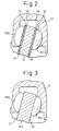
- Fig.2 is an enlarged cross-sectional view of a portion of the compressor of the second embodiment; and
- Fig.3 is an enlarged cross-sectional view of a portion of the compressor of the third embodiment.
-
- A specific embodiment of the present invention is now explained with reference to Figs.1A and 1B.
- Fig.1A shows the internal structure of a variable displacement compressor. A
front housing 12 and acylinder block 11, which form apressure control chamber 121, support a rotatingshaft 13. The rotatingshaft 13 is supplied with a rotational drive force from an external driving source (e.g., vehicle engine). A rotatingsupporter 14 is fixed to the rotatingshaft 13, and aswash plate 15 is supported by the rotatingshaft 13 so as to be able to slide in the axial direction of the rotatingshaft 13 and to tilt with respect to the axial direction. Asupporter 151 is integrally formed with theswash plate 15 made of an iron based material, andguide pins 16 are fixed to thesupporter 151. Theguide pins 16 are slidably inserted inguide holes 141 which are formed in the rotatingsupporter 14. Theswash plate 15 can tilt with respect to the axial direction of the rotatingshaft 13 and rotate with the rotatingshaft 13, by the linkage of theguide pins 16 with theguide holes 141. The tilting motion of theswash plate 15 is guided by the slide guide relation between theguide holes 141 and theguide pins 16 and the slidable support action of the rotatingshaft 13. - The angle of inclination of the
swash plate 15 may be changed by controlling the pressure in thepressure control chamber 121. As the pressure in thepressure control chamber 121 increases, the angle of inclination of theswash plate 15 decreases, and as the pressure in thepressure control chamber 121 decreases, the angle of inclination of the swash plate increases. The coolant in thepressure control chamber 121 flows out to asuction chamber 191 in arear housing 19 through a pressure discharge passage (not shown), and the coolant in adischarge chamber 192 in therear housing 19 is introduced into thepressure control chamber 121 through a pressure supply passage (not shown). Acapacity control valve 25 is disposed in the pressure supply passage, and the flow rate of the coolant supplied from thedischarge chamber 192 to thepressure control chamber 121 is controlled by thecapacity control valve 25. As the flow rate of the coolant supplied from thedischarge chamber 192 to thepressure control chamber 121 increases, the pressure in thepressure control chamber 121 increases, and as the flow rate of the coolant supplied from thedischarge chamber 192 to thepressure control chamber 121 decreases, the pressure in thepressure control chamber 121 decreases. That is, the angle of inclination of theswash plate 15 is controlled by thecapacity control valve 25. - The maximum angle of inclination of the
swash plate 15 is defined as the angle at which theswash plate 15 is in abutment with therotating supporter 14. The minimum angle of inclination of theswash plate 15 is defined as the angle at which theswash plate 15 is in contact with thecirclip 24 on the rotatingshaft 13. - The
cylinder block 11 has a plurality of cylinder bores 111 (only two are shown in Fig.1A) which are disposed around the rotatingshaft 13. Each cylinder bore 111 accommodates apiston 17. The rotational motion of theswash plate 15 rotating with the rotatingshaft 13 is converted into a longitudinal reciprocating motion of thepistons 17 viahemispherical shoes piston 17 moves forward and backward in the cylinder bore 111. Theshoe 18A made of bearing steel makes slide contact with one lubricating surface of theswash plate 15, and theshoe 18B made of bearing steel makes slide contact with the other lubricating surface of theswash plate 15. - Due to the backward motion (the motion from right to left in Fig.1A) of the
piston 17, the coolant in thesuction chamber 191 flows into thecylinder bore 111 from asuction port 201 in avalve plate 20, pushing open asuction valve 211 on avalve forming plate 21. The coolant flowing into thecylinder bore 111 is then discharged, due to the forward motion (the motion from left to light in Fig.1A) of thepiston 17, into thedischarge chamber 192 from adischarge port 202 in thevalve plate 20, pushing open adischarge valve 221 on a valve forming plate 22. The opening of thedischarge valve 221 is limited by aretainer 231 on aretainer forming plate 23. - As shown in Figs.1A and 1B, lubricating
films end surfaces swash plate 15, respectively, which are slide contact areas. Thelubricating films lubricating films surfaces shoes films No. Cu Sn Zn Bi Sb P Ni 1 85.77 11.5 0.1 0.8 0.08 0.15 1.5 2 84.49 10.3 2.5 1.5 1.2 0.01 - 3 84.42 4.5 7.2 3.1 0.6 0.08 0.1 - In the first embodiment, the following effect may be obtained.
- (1-1) In any one of No.1, No.2, and No.3 examples in
Table 1, lead (Pb) is not contained, and bismuth having
low melting point like lead takes the place of lead. That
is, the bismuth contained in the lubricating
films swash plate 15 and theshoes swash plate 15 and theshoes films - (1-2) Under the condition that the degrees of weight percentages of copper and tin (Sn) are the same as No.1, No.2 and No.3, weight percentage of bismuth has been varied, and abrasion-resistance and sticking-resistance of the lubricating film are checked. In the range from 0.5 wt% to 20 wt% of bismuth, reliable abrasion-resistance and sticking-resistance have been obtained. In the range from 0.8 wt% to 10 wt% of bismuth, good abrasion-resistance and sticking-resistance have been obtained.
- (1-3) The end surfaces 26 and 27 of the
swash plate 15 on which the lubricating surface portions are formed are under the severe sliding condition, and the end surfaces 26 and 27 of theswash plate 15 require high sliding performance. For this reason, the end surfaces 26 and 27 which are the slide areas of theswash plate 15 where it makes slide contact with theshoes -
- In the present invention, the second embodiment shown in Fig.2 and the third embodiment shown in Fig.3 are also conceivable. In the second embodiment in Fig.2, lubricating
films films films films - In the third embodiment in Fig.3, the
swash plate 15A itself is made of a copper based material which contains bismuth but does not contain lead. The end surfaces 26 and 27 of theswash plate 15A themselves are lubricating surfaces. - In the present invention, the following embodiments are also conceivable.
- (1) An embodiment, wherein lubricating
films - (2) An embodiment, wherein the present invention is applied to a swash plate of a constant displacement swash plate type compressor.
- (3) An embodiment, wherein the
piston 17 is a component on which a lubricating surface is formed, and the periphery of the piston which makes slide contact with the inner surface of the cylinder bore is the area where the lubricating surface is formed. The following features can be grasped from the embodiments mentioned above. - (4) The component of the compressor, wherein the component itself is made of the copper based material which contains bismuth.
- (5) The component of the compressor, wherein the component itself is made by sintering the powder of the copper based material which contains bismuth.
-
- As described above in detail, in the present invention, bismuth is contained in a copper based material for forming a lubricating surface portion in the slide contact area in a component of a compressor, and thereby good effect may be obtained that slide contact characteristic is good while restricting the amount of lead to be used.
Claims (6)
- A component of a compressor, said component including a lubricating surface portion in a slide contact area, the lubricating surface portion being formed of a copper based material containing bismuth.
- The component according to claim 1, wherein said copper based material comprises copper-tin based alloy.
- The component according to claim 1, wherein said copper based material does not contain lead.
- The component according to one of claims 1 to 3, wherein a lubricating film made of a copper based material containing bismuth is provided in said slide contact area to form said lubricating surface portion.
- The component according to claim 4, wherein said lubricating film is made on a base material by sintering.
- The component according to one of claims 1 to 5, wherein said compressor comprises a swash plate type compressor having a swash plate rotatable with a rotating shaft, a piston, and a shoe disposed between the swash plate and the piston so as to make slide contact with said swash plate and said piston, whereby a rotational motion of said swash plate is transferred to said piston via said shoe to reciprocatingly move said piston, and said component is said swash plate, in which said swash plate has lubricating surface and said shoe has a lubricating surface to make slide contact with the lubricating surface of said swash plate.
Applications Claiming Priority (2)
| Application Number | Priority Date | Filing Date | Title |
|---|---|---|---|
| JP2001054453A JP2002257041A (en) | 2001-02-28 | 2001-02-28 | Object component for forming lubricating surface in compressor |
| JP2001054453 | 2001-02-28 |
Publications (1)
| Publication Number | Publication Date |
|---|---|
| EP1239153A2 true EP1239153A2 (en) | 2002-09-11 |
Family
ID=18914783
Family Applications (1)
| Application Number | Title | Priority Date | Filing Date |
|---|---|---|---|
| EP02003302A Withdrawn EP1239153A2 (en) | 2001-02-28 | 2002-02-13 | Compressor coating |
Country Status (4)
| Country | Link |
|---|---|
| US (1) | US20020157533A1 (en) |
| EP (1) | EP1239153A2 (en) |
| JP (1) | JP2002257041A (en) |
| CN (1) | CN1373291A (en) |
Cited By (2)
| Publication number | Priority date | Publication date | Assignee | Title |
|---|---|---|---|---|
| FR2833318A1 (en) * | 2001-12-06 | 2003-06-13 | Sanden Corp | FLAT CAM TYPE COMPRESSOR |
| EP1980633A1 (en) * | 2007-04-02 | 2008-10-15 | Ed. Fitscher GmbH & Co. KG | Bronze alloy for stand casting |
Families Citing this family (3)
| Publication number | Priority date | Publication date | Assignee | Title |
|---|---|---|---|---|
| CN100451332C (en) * | 2004-11-11 | 2009-01-14 | 大丰工业株式会社 | sliding device |
| CN103629074A (en) * | 2012-08-24 | 2014-03-12 | 苏州轩昌机电科技有限公司 | Compressor swash plate, manufacturing method of compressor swash plate and tool die |
| US10974317B2 (en) * | 2016-07-22 | 2021-04-13 | Emerson Climate Technologies, Inc. | Controlled-dispersion of solid lubricious particles in a metallic alloy matrix |
-
2001
- 2001-02-28 JP JP2001054453A patent/JP2002257041A/en active Pending
-
2002
- 2002-02-13 EP EP02003302A patent/EP1239153A2/en not_active Withdrawn
- 2002-02-18 US US10/078,788 patent/US20020157533A1/en not_active Abandoned
- 2002-02-28 CN CN02106572A patent/CN1373291A/en active Pending
Cited By (2)
| Publication number | Priority date | Publication date | Assignee | Title |
|---|---|---|---|---|
| FR2833318A1 (en) * | 2001-12-06 | 2003-06-13 | Sanden Corp | FLAT CAM TYPE COMPRESSOR |
| EP1980633A1 (en) * | 2007-04-02 | 2008-10-15 | Ed. Fitscher GmbH & Co. KG | Bronze alloy for stand casting |
Also Published As
| Publication number | Publication date |
|---|---|
| CN1373291A (en) | 2002-10-09 |
| JP2002257041A (en) | 2002-09-11 |
| US20020157533A1 (en) | 2002-10-31 |
Similar Documents
| Publication | Publication Date | Title |
|---|---|---|
| EP1036938B1 (en) | Compressor coating | |
| EP1310674B1 (en) | Coating for swash plate compressor | |
| US6584886B2 (en) | Compressor | |
| JP3282457B2 (en) | Single-head piston type compressor | |
| US6568918B2 (en) | Lubrication coating for the sliding portion of a swashplate compressor | |
| JP4258282B2 (en) | Variable capacity swash plate compressor | |
| EP1167761A2 (en) | Swash plate type compressor | |
| US20020157533A1 (en) | Component having slide contact area of compressor | |
| US6666128B2 (en) | Swash plate in swash plate type compressor | |
| US6829980B2 (en) | Component having slide contact area of compressor | |
| US20020046647A1 (en) | Compressors | |
| JP3758244B2 (en) | Variable capacity compressor | |
| JP4496662B2 (en) | Swash plate in swash plate compressor | |
| JPH09209926A (en) | Swash plate type compressor | |
| US20190331105A1 (en) | Swash plate compressor | |
| JPH05195950A (en) | Cam plate type compressor | |
| JPH01219364A (en) | Variable displacement type swash plate compressor | |
| JP3084976B2 (en) | Lubrication structure for one-sided piston variable displacement compressor | |
| JP2003172254A (en) | Swash plate compressor | |
| US20090097990A1 (en) | Swash plate type compressor | |
| KR20010111692A (en) | Surface management of swash plate and piston in compressor for vehicle | |
| KR100210216B1 (en) | Variable typed rotary slant typed compressor | |
| JPH08338363A (en) | Swash plate type compressor | |
| KR20010111693A (en) | Surface coating structure of compressor for vehicle | |
| JP2003065223A (en) | Compressor |
Legal Events
| Date | Code | Title | Description |
|---|---|---|---|
| PUAI | Public reference made under article 153(3) epc to a published international application that has entered the european phase |
Free format text: ORIGINAL CODE: 0009012 |
|
| 17P | Request for examination filed |
Effective date: 20020213 |
|
| AK | Designated contracting states |
Kind code of ref document: A2 Designated state(s): AT BE CH CY DE DK ES FI FR GB GR IE IT LI LU MC NL PT SE TR |
|
| AX | Request for extension of the european patent |
Free format text: AL;LT;LV;MK;RO;SI |
|
| STAA | Information on the status of an ep patent application or granted ep patent |
Free format text: STATUS: THE APPLICATION HAS BEEN WITHDRAWN |
|
| 18W | Application withdrawn |
Effective date: 20030409 |