EP1036938B1 - Compressor coating - Google Patents
Compressor coating Download PDFInfo
- Publication number
- EP1036938B1 EP1036938B1 EP00104565A EP00104565A EP1036938B1 EP 1036938 B1 EP1036938 B1 EP 1036938B1 EP 00104565 A EP00104565 A EP 00104565A EP 00104565 A EP00104565 A EP 00104565A EP 1036938 B1 EP1036938 B1 EP 1036938B1
- Authority
- EP
- European Patent Office
- Prior art keywords
- swash plate
- resin
- coating layer
- metallic particles
- compressor
- Prior art date
- Legal status (The legal status is an assumption and is not a legal conclusion. Google has not performed a legal analysis and makes no representation as to the accuracy of the status listed.)
- Expired - Lifetime
Links
- 239000011248 coating agent Substances 0.000 title description 8
- 238000000576 coating method Methods 0.000 title description 8
- 239000011247 coating layer Substances 0.000 claims description 55
- 239000013528 metallic particle Substances 0.000 claims description 53
- 239000000463 material Substances 0.000 claims description 45
- 239000002245 particle Substances 0.000 claims description 33
- 239000011347 resin Substances 0.000 claims description 29
- 229920005989 resin Polymers 0.000 claims description 29
- 230000002093 peripheral effect Effects 0.000 claims description 22
- 239000007787 solid Substances 0.000 claims description 17
- 229910052751 metal Inorganic materials 0.000 claims description 13
- 239000002184 metal Substances 0.000 claims description 13
- 229920001721 polyimide Polymers 0.000 claims description 12
- 239000000314 lubricant Substances 0.000 claims description 11
- CWQXQMHSOZUFJS-UHFFFAOYSA-N molybdenum disulfide Chemical compound S=[Mo]=S CWQXQMHSOZUFJS-UHFFFAOYSA-N 0.000 claims description 10
- 229910052982 molybdenum disulfide Inorganic materials 0.000 claims description 10
- 239000009719 polyimide resin Substances 0.000 claims description 9
- ATJFFYVFTNAWJD-UHFFFAOYSA-N Tin Chemical compound [Sn] ATJFFYVFTNAWJD-UHFFFAOYSA-N 0.000 claims description 8
- 229910052718 tin Inorganic materials 0.000 claims description 8
- XEEYBQQBJWHFJM-UHFFFAOYSA-N Iron Chemical compound [Fe] XEEYBQQBJWHFJM-UHFFFAOYSA-N 0.000 claims description 7
- OKTJSMMVPCPJKN-UHFFFAOYSA-N Carbon Chemical compound [C] OKTJSMMVPCPJKN-UHFFFAOYSA-N 0.000 claims description 5
- 239000010439 graphite Substances 0.000 claims description 5
- 229910002804 graphite Inorganic materials 0.000 claims description 5
- KXGFMDJXCMQABM-UHFFFAOYSA-N 2-methoxy-6-methylphenol Chemical compound [CH]OC1=CC=CC([CH])=C1O KXGFMDJXCMQABM-UHFFFAOYSA-N 0.000 claims description 4
- PXHVJJICTQNCMI-UHFFFAOYSA-N Nickel Chemical compound [Ni] PXHVJJICTQNCMI-UHFFFAOYSA-N 0.000 claims description 4
- 229910045601 alloy Inorganic materials 0.000 claims description 4
- 239000000956 alloy Substances 0.000 claims description 4
- 239000007769 metal material Substances 0.000 claims description 4
- 239000005011 phenolic resin Substances 0.000 claims description 4
- 229920001568 phenolic resin Polymers 0.000 claims description 4
- 239000000126 substance Substances 0.000 claims description 3
- FYYHWMGAXLPEAU-UHFFFAOYSA-N Magnesium Chemical compound [Mg] FYYHWMGAXLPEAU-UHFFFAOYSA-N 0.000 claims description 2
- ZOKXTWBITQBERF-UHFFFAOYSA-N Molybdenum Chemical compound [Mo] ZOKXTWBITQBERF-UHFFFAOYSA-N 0.000 claims description 2
- 229930182556 Polyacetal Natural products 0.000 claims description 2
- BQCADISMDOOEFD-UHFFFAOYSA-N Silver Chemical compound [Ag] BQCADISMDOOEFD-UHFFFAOYSA-N 0.000 claims description 2
- RTAQQCXQSZGOHL-UHFFFAOYSA-N Titanium Chemical compound [Ti] RTAQQCXQSZGOHL-UHFFFAOYSA-N 0.000 claims description 2
- MUBKMWFYVHYZAI-UHFFFAOYSA-N [Al].[Cu].[Zn] Chemical compound [Al].[Cu].[Zn] MUBKMWFYVHYZAI-UHFFFAOYSA-N 0.000 claims description 2
- 239000003822 epoxy resin Substances 0.000 claims description 2
- 239000007849 furan resin Substances 0.000 claims description 2
- 229910052742 iron Inorganic materials 0.000 claims description 2
- 229910052749 magnesium Inorganic materials 0.000 claims description 2
- 239000011777 magnesium Substances 0.000 claims description 2
- 150000002739 metals Chemical class 0.000 claims description 2
- 229910052750 molybdenum Inorganic materials 0.000 claims description 2
- 239000011733 molybdenum Substances 0.000 claims description 2
- 229910052759 nickel Inorganic materials 0.000 claims description 2
- 229920006122 polyamide resin Polymers 0.000 claims description 2
- 229920000647 polyepoxide Polymers 0.000 claims description 2
- 229920006324 polyoxymethylene Polymers 0.000 claims description 2
- 229910052709 silver Inorganic materials 0.000 claims description 2
- 239000004332 silver Substances 0.000 claims description 2
- 239000010936 titanium Substances 0.000 claims description 2
- 229910052719 titanium Inorganic materials 0.000 claims description 2
- WFKWXMTUELFFGS-UHFFFAOYSA-N tungsten Chemical compound [W] WFKWXMTUELFFGS-UHFFFAOYSA-N 0.000 claims description 2
- 229910052721 tungsten Inorganic materials 0.000 claims description 2
- 239000010937 tungsten Substances 0.000 claims description 2
- 229920006337 unsaturated polyester resin Polymers 0.000 claims description 2
- 239000010410 layer Substances 0.000 description 13
- 239000000203 mixture Substances 0.000 description 11
- 239000000843 powder Substances 0.000 description 10
- 239000011135 tin Substances 0.000 description 10
- 150000002505 iron Chemical class 0.000 description 8
- 238000012360 testing method Methods 0.000 description 8
- 230000000052 comparative effect Effects 0.000 description 6
- 230000001050 lubricating effect Effects 0.000 description 6
- 239000010687 lubricating oil Substances 0.000 description 6
- 238000000034 method Methods 0.000 description 6
- 229910000838 Al alloy Inorganic materials 0.000 description 5
- 238000005516 engineering process Methods 0.000 description 5
- 239000002987 primer (paints) Substances 0.000 description 5
- 230000005856 abnormality Effects 0.000 description 4
- 229920001343 polytetrafluoroethylene Polymers 0.000 description 4
- 239000004810 polytetrafluoroethylene Substances 0.000 description 4
- 239000003507 refrigerant Substances 0.000 description 4
- 238000005507 spraying Methods 0.000 description 4
- 239000004642 Polyimide Substances 0.000 description 3
- 230000015572 biosynthetic process Effects 0.000 description 3
- 238000010276 construction Methods 0.000 description 3
- 239000002826 coolant Substances 0.000 description 3
- 239000011229 interlayer Substances 0.000 description 3
- 238000002156 mixing Methods 0.000 description 3
- AZDRQVAHHNSJOQ-UHFFFAOYSA-N alumane Chemical class [AlH3] AZDRQVAHHNSJOQ-UHFFFAOYSA-N 0.000 description 2
- 239000011230 binding agent Substances 0.000 description 2
- 238000005461 lubrication Methods 0.000 description 2
- 239000011159 matrix material Substances 0.000 description 2
- 229910052961 molybdenite Inorganic materials 0.000 description 2
- 239000004033 plastic Substances 0.000 description 2
- 229910018125 Al-Si Inorganic materials 0.000 description 1
- 229910021364 Al-Si alloy Inorganic materials 0.000 description 1
- 229910018520 Al—Si Inorganic materials 0.000 description 1
- 229910052582 BN Inorganic materials 0.000 description 1
- PZNSFCLAULLKQX-UHFFFAOYSA-N Boron nitride Chemical compound N#B PZNSFCLAULLKQX-UHFFFAOYSA-N 0.000 description 1
- 229910001018 Cast iron Inorganic materials 0.000 description 1
- 229910000881 Cu alloy Inorganic materials 0.000 description 1
- 229910001111 Fine metal Inorganic materials 0.000 description 1
- CBENFWSGALASAD-UHFFFAOYSA-N Ozone Chemical compound [O-][O+]=O CBENFWSGALASAD-UHFFFAOYSA-N 0.000 description 1
- XUIMIQQOPSSXEZ-UHFFFAOYSA-N Silicon Chemical compound [Si] XUIMIQQOPSSXEZ-UHFFFAOYSA-N 0.000 description 1
- 229910002796 Si–Al Inorganic materials 0.000 description 1
- 229910000831 Steel Inorganic materials 0.000 description 1
- 230000001133 acceleration Effects 0.000 description 1
- 239000000853 adhesive Substances 0.000 description 1
- 230000001070 adhesive effect Effects 0.000 description 1
- 229910000410 antimony oxide Inorganic materials 0.000 description 1
- 230000001680 brushing effect Effects 0.000 description 1
- 229910017052 cobalt Inorganic materials 0.000 description 1
- 239000010941 cobalt Substances 0.000 description 1
- GUTLYIVDDKVIGB-UHFFFAOYSA-N cobalt atom Chemical compound [Co] GUTLYIVDDKVIGB-UHFFFAOYSA-N 0.000 description 1
- 239000002131 composite material Substances 0.000 description 1
- 230000006835 compression Effects 0.000 description 1
- 238000007906 compression Methods 0.000 description 1
- 238000001816 cooling Methods 0.000 description 1
- 229910052802 copper Inorganic materials 0.000 description 1
- 239000010949 copper Substances 0.000 description 1
- 230000007812 deficiency Effects 0.000 description 1
- 230000002950 deficient Effects 0.000 description 1
- 239000000428 dust Substances 0.000 description 1
- 230000000694 effects Effects 0.000 description 1
- 238000011156 evaluation Methods 0.000 description 1
- 238000004299 exfoliation Methods 0.000 description 1
- 238000010285 flame spraying Methods 0.000 description 1
- 239000012530 fluid Substances 0.000 description 1
- 239000008240 homogeneous mixture Substances 0.000 description 1
- 229910052738 indium Inorganic materials 0.000 description 1
- APFVFJFRJDLVQX-UHFFFAOYSA-N indium atom Chemical compound [In] APFVFJFRJDLVQX-UHFFFAOYSA-N 0.000 description 1
- 229910000464 lead oxide Inorganic materials 0.000 description 1
- 229910001463 metal phosphate Inorganic materials 0.000 description 1
- VTRUBDSFZJNXHI-UHFFFAOYSA-N oxoantimony Chemical compound [Sb]=O VTRUBDSFZJNXHI-UHFFFAOYSA-N 0.000 description 1
- YEXPOXQUZXUXJW-UHFFFAOYSA-N oxolead Chemical compound [Pb]=O YEXPOXQUZXUXJW-UHFFFAOYSA-N 0.000 description 1
- -1 polytetrafluoroethylene Polymers 0.000 description 1
- 230000001105 regulatory effect Effects 0.000 description 1
- 229910052710 silicon Inorganic materials 0.000 description 1
- 239000010703 silicon Substances 0.000 description 1
- 239000007921 spray Substances 0.000 description 1
- 239000010959 steel Substances 0.000 description 1
- 230000003746 surface roughness Effects 0.000 description 1
- 238000007751 thermal spraying Methods 0.000 description 1
- 229920001187 thermosetting polymer Polymers 0.000 description 1
- ITRNXVSDJBHYNJ-UHFFFAOYSA-N tungsten disulfide Chemical compound S=[W]=S ITRNXVSDJBHYNJ-UHFFFAOYSA-N 0.000 description 1
Images
Classifications
-
- F—MECHANICAL ENGINEERING; LIGHTING; HEATING; WEAPONS; BLASTING
- F04—POSITIVE - DISPLACEMENT MACHINES FOR LIQUIDS; PUMPS FOR LIQUIDS OR ELASTIC FLUIDS
- F04B—POSITIVE-DISPLACEMENT MACHINES FOR LIQUIDS; PUMPS
- F04B27/00—Multi-cylinder pumps specially adapted for elastic fluids and characterised by number or arrangement of cylinders
- F04B27/08—Multi-cylinder pumps specially adapted for elastic fluids and characterised by number or arrangement of cylinders having cylinders coaxial with, or parallel or inclined to, main shaft axis
- F04B27/0873—Component parts, e.g. sealings; Manufacturing or assembly thereof
- F04B27/0878—Pistons
- F04B27/0886—Piston shoes
-
- F—MECHANICAL ENGINEERING; LIGHTING; HEATING; WEAPONS; BLASTING
- F04—POSITIVE - DISPLACEMENT MACHINES FOR LIQUIDS; PUMPS FOR LIQUIDS OR ELASTIC FLUIDS
- F04B—POSITIVE-DISPLACEMENT MACHINES FOR LIQUIDS; PUMPS
- F04B27/00—Multi-cylinder pumps specially adapted for elastic fluids and characterised by number or arrangement of cylinders
- F04B27/08—Multi-cylinder pumps specially adapted for elastic fluids and characterised by number or arrangement of cylinders having cylinders coaxial with, or parallel or inclined to, main shaft axis
- F04B27/10—Multi-cylinder pumps specially adapted for elastic fluids and characterised by number or arrangement of cylinders having cylinders coaxial with, or parallel or inclined to, main shaft axis having stationary cylinders
- F04B27/1036—Component parts, details, e.g. sealings, lubrication
- F04B27/1054—Actuating elements
-
- F—MECHANICAL ENGINEERING; LIGHTING; HEATING; WEAPONS; BLASTING
- F05—INDEXING SCHEMES RELATING TO ENGINES OR PUMPS IN VARIOUS SUBCLASSES OF CLASSES F01-F04
- F05C—INDEXING SCHEME RELATING TO MATERIALS, MATERIAL PROPERTIES OR MATERIAL CHARACTERISTICS FOR MACHINES, ENGINES OR PUMPS OTHER THAN NON-POSITIVE-DISPLACEMENT MACHINES OR ENGINES
- F05C2201/00—Metals
-
- F—MECHANICAL ENGINEERING; LIGHTING; HEATING; WEAPONS; BLASTING
- F05—INDEXING SCHEMES RELATING TO ENGINES OR PUMPS IN VARIOUS SUBCLASSES OF CLASSES F01-F04
- F05C—INDEXING SCHEME RELATING TO MATERIALS, MATERIAL PROPERTIES OR MATERIAL CHARACTERISTICS FOR MACHINES, ENGINES OR PUMPS OTHER THAN NON-POSITIVE-DISPLACEMENT MACHINES OR ENGINES
- F05C2253/00—Other material characteristics; Treatment of material
- F05C2253/12—Coating
-
- F—MECHANICAL ENGINEERING; LIGHTING; HEATING; WEAPONS; BLASTING
- F05—INDEXING SCHEMES RELATING TO ENGINES OR PUMPS IN VARIOUS SUBCLASSES OF CLASSES F01-F04
- F05C—INDEXING SCHEME RELATING TO MATERIALS, MATERIAL PROPERTIES OR MATERIAL CHARACTERISTICS FOR MACHINES, ENGINES OR PUMPS OTHER THAN NON-POSITIVE-DISPLACEMENT MACHINES OR ENGINES
- F05C2253/00—Other material characteristics; Treatment of material
- F05C2253/20—Resin
Definitions
- the present invention relates to a compressor provided with a first and a second member relatively slidably contacted with each other as specified in the preamble of claim 1, and particularly to the improvement in the sliding durability of a coating layer formed on the sliding surface of the two members for the purpose of ensuring contact slidability.
- a compressor coating is known by from US-A-3723165.
- a swash type of compressor is provided with a cylinder block forming part of the housing, a plurality of pistons reciprocatively housed in a plurality of cylinder bores which are formed in the cylinder blocks and a swash plate which is fixed on a drive shaft in an inclined state in a crankcase or which is inclination movably provided to the drive shaft.
- Each of the pistons is movably connected to the peripheral portion of the swash plate through a pair of shoes.
- the movable connecting construction allows the rotary motion of the drive shaft and the swash plate to be converted into a reciprocating motion of the piston.
- atomized lubricating oil is carried by a coolant gas and is supplied to each of the portions of the compressor for the purpose of effecting lubrication.
- the technology disclosed in Japanese Unexamined Patent Publication (Kokai) No. 60-22080 comprises forming, on the metallic base material of a swash plate, a solid lubricating layer prepared by binding molybdenum disulfide and graphite with an adhesive such as a phenolic resin.
- the solid lubricating layer improves the lubricity of the sliding portion surface of the swash plate, makes the contact slidability of the swash plate and the shoes excellent, and improves the seizure resistance of both members.
- EP-A-0 890 743 discloses a swash plate type compressor the swash plate of which being subjected to sliding on shoes.
- the swash plate is provided with a surface-treated layer, said layer comprising an intermediate layer consisting of Cu, Sn or metal phosphate, and a sliding contact layer consisting of MoS 2 and/or graphite and thermosetting resin.
- US-A-4,732,818 discloses a composite bearing material comprising a metal backing, a porous metal interlayer bonded to the metal backing and a polytetrafluoroethylene (PTFE) based composition intermixed with and overlying the porous metal interlayer.
- the porous metal interlayer is applied to the metal backing as a relatively homogeneous mixture of metal powder substantially comprising particles from two distinct particle size ranges, namely, a relatively fine powder range and a relatively coarse powder range.
- An object of the present invention is to improve the durability of a coating layer formed on the sliding surface between two members, a first and a second member relatively slidably contacted with each other, forming a compressor, and to provide a compressor capable of keeping the contact slidability between the two members excellent over a longer period of time.
- the present invention provides a compressor provided with a first and a second member which are relatively slidably contacted with each other, a coating layer which comprises a resin containing metallic particles being formed on at least one of the sliding surface of the first member and that of the second member wherein the coating layer is polished to have a thickness up to a value approximate to the particle size of the metallic particles.
- the metallic particles present in the resin matrix in the coating layer support a load applied thereto from the sliding surface to relatively reduce the load applied to the resin. Accordingly, the presence of the metallic particles increases the durability of the coating layer. The presence of the metallic particles increases the durability of the coating layer.
- the coating layer is polished to have a thickness up to a value approximate to the particle size of the metallic particles.
- a liquid-like mixture of metallic particles and a resin is applied to the base material surface of the members, and the coating layer is cured.
- the surface of the coating layer is then polished until the layer has a thickness up to a value approximate to the particle size of the metallic particles.
- the metallic particles exposed to the surface of the coating layer are directly contacted with the base material, or they are substantially in contact therewith.
- the load applied to the sliding surface is mainly supported by the metallic particles, and as a result the load applied to the resin is relatively reduced. The sliding durability of the coating layer is therefore increased further.
- "a value approximate to the particle size of the metallic particles” is about the particle size of the metallic particles plus 10% of the particle size.
- the compressor to which the present invention is applied is preferably a swash plate type of compressor.
- the swash plate type of compressor is provided with a swash plate and shoes for connecting the peripheral portion of the swash plate to a piston.
- the first and the second member which are relatively slidably contacted with each other are the shoes and the swash plate, respectively.
- the coating layer is formed on at least one of the sliding surfaces. When the coating layer is formed, the coating layer present on the sliding surface of the swash plate and the shoes has high durability; therefore, the slidability of the swash plate and the shoes is kept excellent over a long period of time.
- the particle size of the metallic particles is preferably in the range of 10 to 100 ⁇ m.
- the coating layer thickness for supporting the load becomes thin. Therefore, the coating layer has little sliding durability.
- the coating layer must be made thicker than necessary, and as a result a disadvantage related to the adhesion strength such as exfoliation of the coating layer from the base material results in excessive amounts of materials being required.
- the content of the metallic particles in the coating layer is at least 30% by volume, and preferably up to the volume ratio above which the resin cannot fill the gaps among the metallic particles. Since the volume ratio of the metallic particles is as high as at least 30% by volume, the sliding durability of the coating layer can be obtained. Moreover, since the volume ratio of the metallic particles is up to the one above which the resin cannot fill the gaps among the metallic particles, there are no gaps in the interior and the surface of the coating layer caused by a deficiency in the resin, and the surface smoothness is maintained, which contributes to the lubricity.
- the metallic particles can be present between the surface of the coating layer and the base material (or the primer coating) while forming groups each including, for example, two or three particles which are connected to each other, if the volume content of the metallic particles is high. Consequently, a load can be firmly supported by the base material through the groups of a plurality of the metallic particles connected together; the load applied to the resin is reduced due to the same principle, and the coating layer has a high sliding durability.
- the material of the metallic particles in the coating layer is preferably made to differ from the metallic material of the member on which the coating layer is not formed so that the adhesion of the metallic particles is lowered. Consequently, the metallic particles exposed to the surface of the coating layer are prevented from adhering to the metal of the counterpart member.
- the material of the metallic particles include tin, silver, aluminum, copper, zinc, nickel, silicon, cobalt, titanium, tungsten, molybdenum, magnesium, iron and an alloy containing at least one of the metals mentioned above. Only one material selected from the group mentioned above may be used. Alternatively, a plurality of the materials may also be used. Moreover, other solid lubricants may also be added to the coating layer. The solid lubricant is at least one of molybdenum disulfide and graphite.
- the resin principally functions as a binder for bonding the metallic particles in a powder form to the base material, etc., of the member. Moreover, part of the resin is exposed to the surface as a matrix of the coating layer to smooth the surface, and contributes to the manifestation of the solid lubricity of the surface.
- the method of forming a coating layer comprises, for example, applying a liquid-like mixture of the metallic particles and the resin to the sliding surface of the member, and then baking the coating layer at a suitable temperature. Any of the following procedures can be adopted as the application method: spraying; tumbling; transferring; and brushing.
- the resin material examples include epoxy resin, phenolic resin, furan resin, poliamideimide resin, polyimide resin, polyamide resin, polyacetal resin, fluororesin such as PTFE and unsaturated polyester resin.
- the coating layer can also be formed on the base material through a primer coating (primer coating may be omitted).
- the swash plate type of compressor is provided with a cylinder block 1, a front housing 2 which is joined to the front end of the cylinder block 1 and a rear housing 4 which is joined to the rear end of the cylinder block 1 through a valve plate 3. These are mutually joined together with a plurality of through bolts (omitted in the figure) to form the housing of the compressor.
- the interior of the housing is divided into a crankcase 5, an inlet chamber 6 and an outlet chamber 7.
- a plurality of cylinder bores 1a (only one being shown) are formed in the cylinder block 1.
- a single headed piston 8 is reciprocatively housed in each bore 1a.
- the inlet chamber 6 and the outlet chamber 7 are capable of selectively communicating with each bore 1a through flapper valves provided to the valve plate 3.
- a drive shaft 9 is rotatably supported in the crankcase 5, and a swash plate 10 regarded as a first member is housed therein.
- a shaft bore 10a is penetratively provided to the central portion of the swash plate 10, and the drive shaft 9 is inserted through the shaft bore 10a.
- the swash plate 10 is movably connected to the drive shaft 9 through a hinge mechanism 13 and a lug plate 11, and is movable, with an inclination, to the drive shaft 9 while synchronously rotating with the drive shaft 9 and sliding in the axial direction of the drive shaft 9; a peripheral portion 10d of the swash plate 10 is freely slidably connected to a base end 8a of each piston 8 through a pair of shoes (follower acting as a cam) 20, 20, whereby all the pistons 8 are movably connected to the swash plate 10.
- each piston 8 is reciprocated with a stroke in accordance with an inclination angle of the swash plate.
- inlet and compression of a coolant gas from the inlet chamber 6 region of inlet pressure Ps
- outlet of the compressed refrigerant gas to the outlet chamber 7 region of outlet pressure Pd
- the swash plate 10 is moved toward a position (inclination angle-decreasing position) near the cylinder block 1 by a spring 14 (a spring for urging the swash plate toward its minimum inclination angle position).
- the minimum inclination angle (e.g., 3 to 5°) of the swash plate 10 is restricted by regulating the sliding of the swash plate 10 toward its inclination angle-decreasing position by, for example, a circlip 15 fixed on the drive shaft 9.
- the maximum inclination angle of the swash plate 10 is restricted by, for example, the abutting of a counterweight portion 10b of the swash plate 10 with a defining portion 11a of a lug plate 11.
- the inclination angle of the swash plate 10 can be freely set at an angle between the minimum inclination angle and the maximum inclination angle by adjusting the crank pressure Pc (back pressure of the piston), which is the inner pressure of the crankcase 5, using a displaced control valve 16.
- the swash plate 10 has a land 10c placed in the central area of the swash plate and an annular peripheral portion 10d surrounding the land 10c.
- the land 10c is relatively thick compared with the peripheral portion 10d, and both the shaft bore 10a and the counter weight portion 10b are formed in the land 10c.
- the base end 8a of the piston 8 is provided with a concave portion 8b for admitting the peripheral portion 10d of the swash plate 10 and a pair of shoes 20, 20 regarded as the second member.
- each of the pair of shoes 20 has a spherical convex surface 20a and a flat plane 20b.
- a pair of spherical concave surfaces 8c to be oppositely contacted with the respective spherical convex surfaces 20a of the shoes 20 are formed on the internal surface of the concave portion 8b of the piston 8.
- the pair of shoes 20 are slidably guided on the spherical concave surfaces 8c.
- the swash plate 10 is slidably held by the pair of shoes 20 from the front and rear sides while the front and rear surfaces 22 of the peripheral portion 10d are contacted with the respective flat planes 20b of the shoes 20. That is, the pair of shoes 20 intervening between the pair of spherical concave surfaces 8c and the peripheral portion 10d of the swash plate 10 are rotatably held by the base end 8a of the piston 8, whereby the base end 8a of the piston 8 is connected to the peripheral portion 10d of the swash plate 10 through the pair of the shoes 20.
- the piston 8 is made of an aluminum alloy (e.g., Al-Si alloy), and the swash plate 10 is made of an iron series of material (e.g., cast iron). Moreover, the shoes 20 are formed from a bearing steel which is an iron series of material. In order to lighten the piston 8, an aluminum series of material is used therefor. In order to increase the moment of inertia of the swash plate 10, an iron series of material having a relatively high density is used therefor. Since both the swash plate 10 and the shoes 20 are of an iron series of material, and are composed of metallic materials of the same type, adhesion at the sliding surface is likely to take place.
- Al-Si alloy aluminum alloy
- the swash plate 10 is made of an iron series of material (e.g., cast iron).
- the shoes 20 are formed from a bearing steel which is an iron series of material.
- an aluminum series of material is used therefor.
- an iron series of material having a relatively high density is used therefor. Since both the swash plate
- a film 23 regarded as a coating layer for preventing adhesion is formed on the surfaces 22 of the peripheral portion 10d of the swash plate 10.
- the film 23 is formed on the base material 24 of the swash plate 10.
- the base material 24 of the swash plate 10 on which the film 23 is to be formed is not restricted to an iron series of material; it may also be, for example, an aluminum series of material.
- the film 23 is formed on an area at least including the entire sliding area of the shoes 20. As a result, the shoes 20 slide over the film 23 of the swash plate 10.
- the internal structure of the film 23 and the methods of forming it will be explained in detail in Examples 1 to 2 shown below.
- An aluminum alloy (12% Si-Al) having a particle size of about 70 ⁇ m was used as metallic particles.
- the aluminum alloy powder and a polyimide resin regarded as a resin were mixed in a mixing ratio of the alloy to the resin of 65 wt% to 35 wt% to give a liquid-like mixture.
- the surface of the base material of a swash plate formed from an iron series of material was cleaned, and degreased.
- the liquid-like mixture of a polyimide resin containing dispersed aluminum alloy particles was applied to both peripheral surfaces of the base material of the swash plate by spraying. After the application, the coating was baked at 200°C to complete film formation.
- the film surface was polished to form a film 23 having a thickness of about 50 ⁇ m.
- Tin (Sn) having a particle size of about 40 to 50 ⁇ m was used as metallic particles.
- the tin powder and a polyimide resin regarded as a resin were mixed in a mixing ratio of tin to the resin of 80 wt% to 20 wt% to give a liquid-like mixture.
- the surface of the base material of a swash plate formed from an iron series of material was cleaned and degreased.
- the liquid-like mixture of a polyimide resin containing dispersed tin particles was applied to both peripheral surfaces of the base material of the swash plate by spraying. After the application, the coating was baked at 200°C to complete film formation.
- the film surface was polished to form a film 23 having a thickness of about 50 ⁇ m.
- Molybdenum disulfide having a particle size of about 1 ⁇ m was used as a solid lubricant.
- the molybdenum disulfide powder and a polyimide resin regarded as a resin were mixed in a mixing ratio of the molybdenum disulfide to the resin of 60 wt% to 40 wt% to give a liquid-like mixture.
- the surface of the base material of a swash plate formed from an iron series of material was cleaned and degreased.
- the liquid-like mixture of a polyimide resin containing dispersed molybdenum disulfide particles was applied to both peripheral surfaces of the base material of the swash plate by spraying. After the application, the coating was baked at 200°C to complete film formation.
- the film surface was polished to form a film 23 having a thickness of about 50 ⁇ m.
- a swash plate such as the one in any of Examples and Comparative Examples mentioned above was incorporated as shown in Fig. 1
- an acceleration testing machine was used, and a continuous sliding durability test was conducted between the swash plate and the shoes.
- two pairs of shoes were arranged on the peripheral surface of the swash plate at two respective sites situated at both respective end portions of a diameter of the swash plate, in such a manner that the respective end faces of the shoes were contacted with the peripheral surface and were placed in a state where the shoes press-contacted the swash plate surface due to forces from two springs.
- the swash plate was rotated at high speed in such a state.
- the contact pressure between the shoes and the swash plate was set in accordance with the actual machine. Moreover, in the test, a state immediately after starting the actual machine was estimated, and lubricating oil conditions (fluid lubrication conditions) in an oilless environment (assuming that the amount of the lubricating oil being about 10% of an ordinary one) were adopted.
- the number of revolution of the swash plate was determined to be 9,200 rpm which is about twice the number of ordinary revolution of the actual machine, and the swash plate was rotated at the rotation speed for 8 hours.
- Table 1 summarizes the material construction of the swash plates in Example 1 to 2 and Comparative Example, and the test results. Occurrence of troubles such as seizure between the shoes and the swash plate was visually observed after the test.
- a film 23 comprising a mixture of aluminum alloy particles or tin particles and a polyimide resin was formed on the peripheral surface of a swash plate
- neither the sliding surface of the swash plate nor that of the shoes showed abnormality.
- Comparative Example wherein a solid lubricating layer is formed on the peripheral surface of a swash plate, abnormality related to seizure was observed to some degree on the surface.
- the mode of operation of the present invention is not restricted to that mentioned above.
- the present invention can also be operated in the embodiments (A) to (F).
- the present invention improves the durability of the coating layer formed on the sliding surface between two members forming a compressor, and can preserve the contact slidability between the two members excellent over a long period of time.
Description
- The present invention relates to a compressor provided with a first and a second member relatively slidably contacted with each other as specified in the preamble of claim 1, and particularly to the improvement in the sliding durability of a coating layer formed on the sliding surface of the two members for the purpose of ensuring contact slidability. Such a compressor coating is known by from US-A-3723165.
- In general, a swash type of compressor is provided with a cylinder block forming part of the housing, a plurality of pistons reciprocatively housed in a plurality of cylinder bores which are formed in the cylinder blocks and a swash plate which is fixed on a drive shaft in an inclined state in a crankcase or which is inclination movably provided to the drive shaft. Each of the pistons is movably connected to the peripheral portion of the swash plate through a pair of shoes. The movable connecting construction allows the rotary motion of the drive shaft and the swash plate to be converted into a reciprocating motion of the piston.
- For such a swash type of compressor, it has become important to avoid seizure between the swash plate and the pair of shoes which are directly contacted with both surfaces of the peripheral portion of the swash plate, and to reduce friction between the swash plate and the shoes for the reasons explained below. For a swash type of compressor, atomized lubricating oil is carried by a coolant gas and is supplied to each of the portions of the compressor for the purpose of effecting lubrication. However, lubricating oil remaining in and adhering to the sliding surface of the swash plate is washed by the coolant gas before the atomized lubricating oil reaches the swash plate, and the swash plate surface is likely to become dry where the swash plate surface is deficient in lubricating oil. As a result, the swash plate and the shoes are forced to start sliding under dry conditions. The sliding conditions, namely, the sliding environment, of the swash plate is thus very severe. Moreover, so-called new refrigerant, such as R134a, which have recently started to be used in place of conventional cooling refrigerant for the purpose of protecting the ozone layer are more likely to manifest the dry state than the conventional refrigerant. Improvement in the lubricity of the swash plate surface has therefore been required still more.
- Conventional technologies which are intended to solve such problems by surface treating the swash plate are disclosed in Japanese Unexamined Patent Publication (Kokai) JP 60022080 (Japanese Examined Patent Publication (Kokoku) JP 5010513), International Publication WO 95/25224 and Japanese Unexamined Patent Publication (Kokai) JP 8199327.
- Of these conventional technologies, the technology disclosed in Japanese Unexamined Patent Publication (Kokai) No. 60-22080, for example, comprises forming, on the metallic base material of a swash plate, a solid lubricating layer prepared by binding molybdenum disulfide and graphite with an adhesive such as a phenolic resin. The solid lubricating layer improves the lubricity of the sliding portion surface of the swash plate, makes the contact slidability of the swash plate and the shoes excellent, and improves the seizure resistance of both members.
- From US-A-3,723,165 the flame spraying of high temperature plastic powder in admixture with a flame spray metal powder is known. This document specifies a lubricating coating applicable on bearing surfaces to be used inter alia in compressors. The coating comprises a very fine metal powder or dust having a particle size between about 25 µm and 0,5 µm, which is bonded to the surface of a plastic as for example with a binding agent such as phenolic resin.
- EP-A-0 890 743 discloses a swash plate type compressor the swash plate of which being subjected to sliding on shoes. The swash plate is provided with a surface-treated layer, said layer comprising an intermediate layer consisting of Cu, Sn or metal phosphate, and a sliding contact layer consisting of MoS2 and/or graphite and thermosetting resin.
- US-A-4,732,818 discloses a composite bearing material comprising a metal backing, a porous metal interlayer bonded to the metal backing and a polytetrafluoroethylene (PTFE) based composition intermixed with and overlying the porous metal interlayer. The porous metal interlayer is applied to the metal backing as a relatively homogeneous mixture of metal powder substantially comprising particles from two distinct particle size ranges, namely, a relatively fine powder range and a relatively coarse powder range.
- However, although desired lubricity can be obtained by any of the conventional technologies, sufficient durability of the coating layer formed on the sliding surfaces of the swash plate and the shoes has not been obtained. That is, when the swash plate is repeatedly used under dry conditions, the coating layer is sometimes abraded or exfoliated to form a hole, which results in exposure of the base material.
- An object of the present invention is to improve the durability of a coating layer formed on the sliding surface between two members, a first and a second member relatively slidably contacted with each other, forming a compressor, and to provide a compressor capable of keeping the contact slidability between the two members excellent over a longer period of time.
- The present invention provides a compressor provided with a first and a second member which are relatively slidably contacted with each other, a coating layer which comprises a resin containing metallic particles being formed on at least one of the sliding surface of the first member and that of the second member wherein the coating layer is polished to have a thickness up to a value approximate to the particle size of the metallic particles. The metallic particles present in the resin matrix in the coating layer support a load applied thereto from the sliding surface to relatively reduce the load applied to the resin. Accordingly, the presence of the metallic particles increases the durability of the coating layer. The presence of the metallic particles increases the durability of the coating layer. The coating layer is polished to have a thickness up to a value approximate to the particle size of the metallic particles. For example, a liquid-like mixture of metallic particles and a resin is applied to the base material surface of the members, and the coating layer is cured. The surface of the coating layer is then polished until the layer has a thickness up to a value approximate to the particle size of the metallic particles. The metallic particles exposed to the surface of the coating layer are directly contacted with the base material, or they are substantially in contact therewith. The load applied to the sliding surface is mainly supported by the metallic particles, and as a result the load applied to the resin is relatively reduced. The sliding durability of the coating layer is therefore increased further. In addition, "a value approximate to the particle size of the metallic particles" is about the particle size of the metallic particles plus 10% of the particle size.
- The compressor to which the present invention is applied is preferably a swash plate type of compressor. The swash plate type of compressor is provided with a swash plate and shoes for connecting the peripheral portion of the swash plate to a piston. The first and the second member which are relatively slidably contacted with each other are the shoes and the swash plate, respectively. The coating layer is formed on at least one of the sliding surfaces. When the coating layer is formed, the coating layer present on the sliding surface of the swash plate and the shoes has high durability; therefore, the slidability of the swash plate and the shoes is kept excellent over a long period of time.
- The particle size of the metallic particles is preferably in the range of 10 to 100 µm. When the particle size is less than 10 µm, the coating layer thickness for supporting the load becomes thin. Therefore, the coating layer has little sliding durability. Furthermore, when the particle size exceeds 100 µm, the coating layer must be made thicker than necessary, and as a result a disadvantage related to the adhesion strength such as exfoliation of the coating layer from the base material results in excessive amounts of materials being required.
- The content of the metallic particles in the coating layer is at least 30% by volume, and preferably up to the volume ratio above which the resin cannot fill the gaps among the metallic particles. Since the volume ratio of the metallic particles is as high as at least 30% by volume, the sliding durability of the coating layer can be obtained. Moreover, since the volume ratio of the metallic particles is up to the one above which the resin cannot fill the gaps among the metallic particles, there are no gaps in the interior and the surface of the coating layer caused by a deficiency in the resin, and the surface smoothness is maintained, which contributes to the lubricity. Moreover, even when the particle size of the metallic particles is as small as about 10 µm, and smaller than a value approximate to the coating thickness, the metallic particles can be present between the surface of the coating layer and the base material (or the primer coating) while forming groups each including, for example, two or three particles which are connected to each other, if the volume content of the metallic particles is high. Consequently, a load can be firmly supported by the base material through the groups of a plurality of the metallic particles connected together; the load applied to the resin is reduced due to the same principle, and the coating layer has a high sliding durability.
- When the coating layer is formed on the surface of only one of the first and the second member, the material of the metallic particles in the coating layer is preferably made to differ from the metallic material of the member on which the coating layer is not formed so that the adhesion of the metallic particles is lowered. Consequently, the metallic particles exposed to the surface of the coating layer are prevented from adhering to the metal of the counterpart member.
- Specific examples of the material of the metallic particles include tin, silver, aluminum, copper, zinc, nickel, silicon, cobalt, titanium, tungsten, molybdenum, magnesium, iron and an alloy containing at least one of the metals mentioned above. Only one material selected from the group mentioned above may be used. Alternatively, a plurality of the materials may also be used. Moreover, other solid lubricants may also be added to the coating layer. The solid lubricant is at least one of molybdenum disulfide and graphite.
- The resin principally functions as a binder for bonding the metallic particles in a powder form to the base material, etc., of the member. Moreover, part of the resin is exposed to the surface as a matrix of the coating layer to smooth the surface, and contributes to the manifestation of the solid lubricity of the surface. The method of forming a coating layer comprises, for example, applying a liquid-like mixture of the metallic particles and the resin to the sliding surface of the member, and then baking the coating layer at a suitable temperature. Any of the following procedures can be adopted as the application method: spraying; tumbling; transferring; and brushing. Examples of the resin material include epoxy resin, phenolic resin, furan resin, poliamideimide resin, polyimide resin, polyamide resin, polyacetal resin, fluororesin such as PTFE and unsaturated polyester resin. One of or a combination of a plurality of such resins can be used. In addition, the coating layer can also be formed on the base material through a primer coating (primer coating may be omitted).
-
- [Fig. 1]
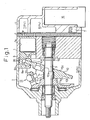
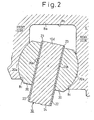
Fig. 1 is a longitudinal sectional view of a single headed piston swash type of compressor to which the present invention is applied. - [Fig. 2]
Fig. 2 is an expanded sectional view showing an outline of the relationship between a swash plate and shoes. - First, one embodiment of a volume-variable swash plate type of compressor which is the object of the present invention will be briefly explained. As shown in Fig. 1, the swash plate type of compressor is provided with a cylinder block 1, a front housing 2 which is joined to the front end of the cylinder block 1 and a rear housing 4 which is joined to the rear end of the cylinder block 1 through a valve plate 3. These are mutually joined together with a plurality of through bolts (omitted in the figure) to form the housing of the compressor. The interior of the housing is divided into a
crankcase 5, aninlet chamber 6 and anoutlet chamber 7. A plurality of cylinder bores 1a (only one being shown) are formed in the cylinder block 1. A single headedpiston 8 is reciprocatively housed in each bore 1a. Theinlet chamber 6 and theoutlet chamber 7 are capable of selectively communicating with each bore 1a through flapper valves provided to the valve plate 3. - A
drive shaft 9 is rotatably supported in thecrankcase 5, and aswash plate 10 regarded as a first member is housed therein. Ashaft bore 10a is penetratively provided to the central portion of theswash plate 10, and thedrive shaft 9 is inserted through theshaft bore 10a. Theswash plate 10 is movably connected to thedrive shaft 9 through ahinge mechanism 13 and a lug plate 11, and is movable, with an inclination, to thedrive shaft 9 while synchronously rotating with thedrive shaft 9 and sliding in the axial direction of thedrive shaft 9; aperipheral portion 10d of theswash plate 10 is freely slidably connected to abase end 8a of eachpiston 8 through a pair of shoes (follower acting as a cam) 20, 20, whereby all thepistons 8 are movably connected to theswash plate 10. When theswash plate 10 inclined at a given angle is rotated together with thedrive shaft 9, eachpiston 8 is reciprocated with a stroke in accordance with an inclination angle of the swash plate. In each cylinder bore 1a, inlet and compression of a coolant gas from the inlet chamber 6 (region of inlet pressure Ps), and outlet of the compressed refrigerant gas to the outlet chamber 7 (region of outlet pressure Pd) are consecutively repeated. - The
swash plate 10 is moved toward a position (inclination angle-decreasing position) near the cylinder block 1 by a spring 14 (a spring for urging the swash plate toward its minimum inclination angle position). However, the minimum inclination angle (e.g., 3 to 5°) of theswash plate 10 is restricted by regulating the sliding of theswash plate 10 toward its inclination angle-decreasing position by, for example, acirclip 15 fixed on thedrive shaft 9. On the other hand, the maximum inclination angle of theswash plate 10 is restricted by, for example, the abutting of acounterweight portion 10b of theswash plate 10 with a definingportion 11a of a lug plate 11. - For the swash plate type of compressor in Fig. 1, the inclination angle of the
swash plate 10 can be freely set at an angle between the minimum inclination angle and the maximum inclination angle by adjusting the crank pressure Pc (back pressure of the piston), which is the inner pressure of thecrankcase 5, using a displacedcontrol valve 16. - The
swash plate 10 has aland 10c placed in the central area of the swash plate and an annularperipheral portion 10d surrounding theland 10c. Theland 10c is relatively thick compared with theperipheral portion 10d, and both the shaft bore 10a and thecounter weight portion 10b are formed in theland 10c. Furthermore, thebase end 8a of thepiston 8 is provided with aconcave portion 8b for admitting theperipheral portion 10d of theswash plate 10 and a pair ofshoes - Next, the surface structure, etc., of the swash plate which is the feature of the present invention will be explained by making reference to Fig. 2. As shown in Fig. 2, each of the pair of
shoes 20 has a sphericalconvex surface 20a and aflat plane 20b. A pair of sphericalconcave surfaces 8c to be oppositely contacted with the respective sphericalconvex surfaces 20a of theshoes 20 are formed on the internal surface of theconcave portion 8b of thepiston 8. The pair ofshoes 20 are slidably guided on the sphericalconcave surfaces 8c. Theswash plate 10 is slidably held by the pair ofshoes 20 from the front and rear sides while the front andrear surfaces 22 of theperipheral portion 10d are contacted with the respectiveflat planes 20b of theshoes 20. That is, the pair ofshoes 20 intervening between the pair of sphericalconcave surfaces 8c and theperipheral portion 10d of theswash plate 10 are rotatably held by thebase end 8a of thepiston 8, whereby thebase end 8a of thepiston 8 is connected to theperipheral portion 10d of theswash plate 10 through the pair of theshoes 20. In addition, of thesurface 22 of theperipheral portion 10d of theswash plate 10, the portion which slides over theflat plane 20b of theshoes 20 becomes the sliding surface of the swash plate side, and theflat planes 20b of theshoes 20 become the sliding surfaces of the shoe sides. - The
piston 8 is made of an aluminum alloy (e.g., Al-Si alloy), and theswash plate 10 is made of an iron series of material (e.g., cast iron). Moreover, theshoes 20 are formed from a bearing steel which is an iron series of material. In order to lighten thepiston 8, an aluminum series of material is used therefor. In order to increase the moment of inertia of theswash plate 10, an iron series of material having a relatively high density is used therefor. Since both theswash plate 10 and theshoes 20 are of an iron series of material, and are composed of metallic materials of the same type, adhesion at the sliding surface is likely to take place. Accordingly, afilm 23 regarded as a coating layer for preventing adhesion is formed on thesurfaces 22 of theperipheral portion 10d of theswash plate 10. Thefilm 23 is formed on thebase material 24 of theswash plate 10. In addition, thebase material 24 of theswash plate 10 on which thefilm 23 is to be formed is not restricted to an iron series of material; it may also be, for example, an aluminum series of material. - On the
surfaces 22 of theperipheral portion 10d of theswash plate 10, thefilm 23 is formed on an area at least including the entire sliding area of theshoes 20. As a result, theshoes 20 slide over thefilm 23 of theswash plate 10. The internal structure of thefilm 23 and the methods of forming it will be explained in detail in Examples 1 to 2 shown below. - Next, Examples 1 to 2 showing specific instances of a
film 23 formed on the surface of aswash plate 10 and Comparative Example belonging to the category of the conventional technology will be explained. - An aluminum alloy (12% Si-Al) having a particle size of about 70 µm was used as metallic particles. The aluminum alloy powder and a polyimide resin regarded as a resin were mixed in a mixing ratio of the alloy to the resin of 65 wt% to 35 wt% to give a liquid-like mixture. The surface of the base material of a swash plate formed from an iron series of material was cleaned, and degreased. The liquid-like mixture of a polyimide resin containing dispersed aluminum alloy particles was applied to both peripheral surfaces of the base material of the swash plate by spraying. After the application, the coating was baked at 200°C to complete film formation. The film surface was polished to form a
film 23 having a thickness of about 50 µm. - Tin (Sn) having a particle size of about 40 to 50 µm was used as metallic particles. The tin powder and a polyimide resin regarded as a resin were mixed in a mixing ratio of tin to the resin of 80 wt% to 20 wt% to give a liquid-like mixture. The surface of the base material of a swash plate formed from an iron series of material was cleaned and degreased. The liquid-like mixture of a polyimide resin containing dispersed tin particles was applied to both peripheral surfaces of the base material of the swash plate by spraying. After the application, the coating was baked at 200°C to complete film formation. The film surface was polished to form a
film 23 having a thickness of about 50 µm. - Molybdenum disulfide having a particle size of about 1 µm was used as a solid lubricant. The molybdenum disulfide powder and a polyimide resin regarded as a resin were mixed in a mixing ratio of the molybdenum disulfide to the resin of 60 wt% to 40 wt% to give a liquid-like mixture. The surface of the base material of a swash plate formed from an iron series of material was cleaned and degreased. The liquid-like mixture of a polyimide resin containing dispersed molybdenum disulfide particles was applied to both peripheral surfaces of the base material of the swash plate by spraying. After the application, the coating was baked at 200°C to complete film formation. The film surface was polished to form a
film 23 having a thickness of about 50 µm. - Assuming that the actual machine was a swash type of compressor into which a swash plate such as the one in any of Examples and Comparative Examples mentioned above was incorporated as shown in Fig. 1, an acceleration testing machine was used, and a continuous sliding durability test was conducted between the swash plate and the shoes. In the testing machine, two pairs of shoes were arranged on the peripheral surface of the swash plate at two respective sites situated at both respective end portions of a diameter of the swash plate, in such a manner that the respective end faces of the shoes were contacted with the peripheral surface and were placed in a state where the shoes press-contacted the swash plate surface due to forces from two springs. The swash plate was rotated at high speed in such a state. The contact pressure between the shoes and the swash plate was set in accordance with the actual machine. Moreover, in the test, a state immediately after starting the actual machine was estimated, and lubricating oil conditions (fluid lubrication conditions) in an oilless environment (assuming that the amount of the lubricating oil being about 10% of an ordinary one) were adopted. The number of revolution of the swash plate was determined to be 9,200 rpm which is about twice the number of ordinary revolution of the actual machine, and the swash plate was rotated at the rotation speed for 8 hours.
- Table 1 summarizes the material construction of the swash plates in Example 1 to 2 and Comparative Example, and the test results. Occurrence of troubles such as seizure between the shoes and the swash plate was visually observed after the test. In each of Examples 1 to 2 wherein a
film 23 comprising a mixture of aluminum alloy particles or tin particles and a polyimide resin was formed on the peripheral surface of a swash plate, neither the sliding surface of the swash plate nor that of the shoes showed abnormality. In contrast, in Comparative Example wherein a solid lubricating layer is formed on the peripheral surface of a swash plate, abnormality related to seizure was observed to some degree on the surface. Since the solid lubricating layer produces effects to some degree in the actual machine, the films in Examples 1 to 2 were confirmed to be more excellent than the solid lubricating layer, in view of the sliding durability.Table 1 Material construction of a swash plate Base Material Test Results Film Particles contained Resin Example 1 Al-Si series of alloy 70 µm Polyimide Fe series No abnormality ○ Example 2 Sn 40 to 50 µm Polyimide Fe series No abnormality ○ Comparative Example MoS2 1 µm Polyimide Fe series Seizure △ - In addition, the mode of operation of the present invention is not restricted to that mentioned above. The present invention can also be operated in the embodiments (A) to (F).
- (A) A solid lubricant can also be added to the coating layer. Examples of the solid lubricant include molybdenum disulfide, tungsten disulfide, graphite, boron nitride, antimony oxide, lead oxide, lead (Pb), indium (In), tin (Sn) and PTFE. The solid lubricant component to be used is preferably at least one substance selected from the group mentioned above. Moreover, a plurality of the substances can also be used in a mixture as the solid lubricant component.
In addition, although the solid lubricant component includes metal, the metal differs from the metallic particles of the present invention in that the metallic particles are particles (particulate). Moreover, the particle size of the metallic particles is preferably at least a value approximate to the thickness of the coating layer, and larger than the particle size of the solid lubricant in powder. Furthermore, the morphology of the metallic particles preferably is isotropic. When the morphology of the metallic particles is anisotropic, for example, scale-like (flake-like) or needle-like, the metallic particles come to be oriented in the coating layer (film 23) in the layer direction. The coating layer therefore does not have sliding durability. Still further, the content of the metallic particles is preferably high. For example, the content is preferably at least 30% by volume, more preferably at least 40% by volume, and most preferably at least 50% by volume. When the volume content of the metallic particles is high, that is, when the filling factor is high, the metallic particles easily support the load, and contribute to the improvement in the sliding durability of the coating layer. - (B) The particle size of the metallic particles may be smaller than a size approximate to the thickness of the coating layer (film 23). For example, the particle size of the metallic particles is determined to be from 10 to 20 µm, and the thickness of the coating layer can be made about twice the particle size thereof. In this case, when the volume ratio of the metallic particles is high, the metallic particles are present between the coating layer surface and the base material surface while they are linked to each other. As a result, the metallic particles effectively support the load to increase the sliding durability of the coating layer.
- (C) A primer coating different from the base material may also be formed below the
film 23. For example, a copper alloy layer can be formed as the primer coating by a procedure such as thermal spraying. - (D) The surface of the
base material 24 of theswash plate 10 can be surface roughened (the surface roughness being, for example, from 3 to 10 µm) to improve the adhesion of thefilm 23 to thebase material 24. - (E) The portion to which the present invention can be applied is not restricted to the sliding portion between the swash plate and the shoes, but the present invention may be applied to the contact sliding portions (a) to (c) shown below. That is, examples of a combination of the first and the second member are mentioned below:
- (a) A portion between the
shoes 20 and thepiston 8; - (b) A portion between the
drive shaft 9 and theswash plate 10; and - (c) A portion between the peripheral surface of the
piston 8 and the inner surface of the cylinder bore 1a of the cylinder block 1
- (a) A portion between the
- (F) The application of the present invention is not restricted to the swash type of compressor, but it may be applied to another type of compressor such as a scroll type of compressor.
- The technical ideas other than those in the claims but shown in the above embodiments and other instances will be described below.
- (1) In
claim 5, the content of the metallic particles is at least 40% by volume. - (2) In the technical idea mentioned in (1), the content thereof is at least 50% by volume.
- (3) In claim 4, the particle size (average particle size) of the metallic particles is in the range of 30 to 80 µm. In this case, the sliding durability of the coating layer is increased and thickness control of the coating layer becomes easy.
- As explained above in detail, the present invention improves the durability of the coating layer formed on the sliding surface between two members forming a compressor, and can preserve the contact slidability between the two members excellent over a long period of time.
Claims (9)
- A compressor provided with a first and a second member (10, 20) which are relatively slidably contacted with each other, a coating layer (23), which comprises a resin containing metallic particles, being formed on at least one of the sliding surface of the first member and that of the second member (10, 20), characterised in that the coating layer (23) is polished to have a thickness up to a value approximate to the particle size of the metallic particles.
- The compressor according to claim 1 characterised in that the compressor is a swash plate type of compressor, the swash plate type of compressor is provided with a swash plate (10) and shoes (20) for connecting the peripheral portion of the swash plate (10) to a piston (8) as the first and the second member which are relatively slidably contacted with each other, and the coating layer (23) is formed on at least one of the swash plate surface and the sliding surface of the shoes (20).
- The compressor according to claim 1, or claim 2 characterised in that the particle size of the metallic particles is in the range from 10 to 100 µm.
- The compressor according to at least one of claim 1 to claim 3 characterised in that the content of the metallic particles is at least 30% by volume and up to the volume ratio above which the resin cannot fill the gaps among the metallic particles.
- The compressor according to at least one of claim 1 to claim 4 characterised in that the coating layer is formed only on one of the first and the second member (10, 20), and the material of the metallic particles in the coating layer (23) differs from the metallic material of the member (10, 20) on which the coating layer (23) is not formed, and shows poor adhesion to the metallic material.
- The compressor according to at least one of claim 1 to claim 5 characterised in that the material of the metallic particles is composed of one or a plurality of substances selected from the group consisting of tin, silver, aluminum, copper, zinc, nickel, titanium, tungsten, molybdenum, magnesium, iron and an alloy containing at least one of the metals mentioned above.
- The compressor according to at least one of claim 1 to claim 6 characterised in that the resin material is one or a plurality of materials selected from the group consisting of epoxy resin, phenolic resin, furan resin, poliamideimide resin, polyimide resin, polyamide resin, polyacetal resin, fluororesin and unsaturated polyester resin.
- The compressor according to at least one of claim 1 to claim 7 characterised in that the coating layer (23) contains a solid lubricant.
- The compressor according to at least one of claim 1 to claim 8 characterised in that the solid lubricant is at least one of molybdenum disulfide and graphite.
Applications Claiming Priority (2)
| Application Number | Priority Date | Filing Date | Title |
|---|---|---|---|
| JP7226299 | 1999-03-17 | ||
| JP07226299A JP4001257B2 (en) | 1999-03-17 | 1999-03-17 | Compressor |
Publications (3)
| Publication Number | Publication Date |
|---|---|
| EP1036938A2 EP1036938A2 (en) | 2000-09-20 |
| EP1036938A3 EP1036938A3 (en) | 2001-02-28 |
| EP1036938B1 true EP1036938B1 (en) | 2006-06-14 |
Family
ID=13484209
Family Applications (1)
| Application Number | Title | Priority Date | Filing Date |
|---|---|---|---|
| EP00104565A Expired - Lifetime EP1036938B1 (en) | 1999-03-17 | 2000-03-13 | Compressor coating |
Country Status (4)
| Country | Link |
|---|---|
| US (1) | US6378415B1 (en) |
| EP (1) | EP1036938B1 (en) |
| JP (1) | JP4001257B2 (en) |
| DE (1) | DE60028631T2 (en) |
Families Citing this family (32)
| Publication number | Priority date | Publication date | Assignee | Title |
|---|---|---|---|---|
| JP3259777B2 (en) * | 1999-11-26 | 2002-02-25 | 大豊工業株式会社 | Hemispherical shoe |
| JP2001335812A (en) * | 2000-03-24 | 2001-12-04 | Senju Metal Ind Co Ltd | Lead-free plain bearing and its production method |
| JP2002039062A (en) * | 2000-07-26 | 2002-02-06 | Toyota Industries Corp | Compressor |
| JP2002089437A (en) * | 2000-09-13 | 2002-03-27 | Toyota Industries Corp | Film forming objective part for lubrication in compressor |
| JP4547829B2 (en) * | 2000-10-03 | 2010-09-22 | 株式会社豊田自動織機 | Swash plate in swash plate compressor |
| US6706415B2 (en) * | 2000-12-28 | 2004-03-16 | Copeland Corporation | Marine coating |
| JP2002257042A (en) * | 2001-02-28 | 2002-09-11 | Toyota Industries Corp | Object component for forming lubricating surface in compressor |
| JP4496662B2 (en) * | 2001-04-20 | 2010-07-07 | 株式会社豊田自動織機 | Swash plate in swash plate compressor |
| JP2002317759A (en) * | 2001-04-25 | 2002-10-31 | Toyota Industries Corp | Shoe for swash plate-type compressor and swash plate- type compressor having the same |
| KR20020092483A (en) * | 2001-06-04 | 2002-12-12 | 한라공조주식회사 | Swash plate and compressor utilizing the same |
| JP2003049766A (en) * | 2001-08-03 | 2003-02-21 | Toyota Industries Corp | Sliding part and compressor |
| DE10203295B4 (en) * | 2002-01-29 | 2005-01-27 | Görlach, Bernd, Dr. | Bearing or drive device with coated elements |
| JP4232506B2 (en) * | 2002-06-24 | 2009-03-04 | 株式会社豊田自動織機 | Sliding parts |
| DE10322352A1 (en) * | 2002-06-24 | 2004-01-22 | Volkswagen Ag | Electrically driven compressor for a vehicle air conditioning system |
| JP4359066B2 (en) * | 2003-04-14 | 2009-11-04 | 株式会社豊田自動織機 | Sliding part coating composition |
| JP4025832B2 (en) * | 2003-04-14 | 2007-12-26 | 株式会社豊田自動織機 | Compressor |
| JP4214827B2 (en) * | 2003-04-22 | 2009-01-28 | 株式会社豊田自動織機 | Compressor sliding parts |
| EP1489152A3 (en) * | 2003-06-19 | 2005-09-07 | Dow Corning Asia, Ltd. | Coating composition for use in sliding members |
| JP4049082B2 (en) * | 2003-06-19 | 2008-02-20 | 株式会社豊田自動織機 | Compressor |
| US20050084388A1 (en) * | 2003-07-17 | 2005-04-21 | Hayes Alan E. | Positive displacement liquid pump |
| US7001077B2 (en) | 2003-11-04 | 2006-02-21 | Goerlach Bernd | Bearing or drive assembly with coated elements |
| DE102005023457A1 (en) | 2004-05-21 | 2005-12-15 | Kabushiki Kaisha Toyota Jidoshokki, Kariya | Sliding film, sliding member, lubricating film composition, sliding device, swash plate type compressor, method of forming a sliding film, and method of manufacturing a sliding member |
| JP2006008994A (en) * | 2004-05-21 | 2006-01-12 | Toyota Central Res & Dev Lab Inc | Sliding film, sliding member, composition for sliding film, sliding device, swash-plate type compressor, process for forming sliding film, and process for producing sliding member |
| JP2006002716A (en) * | 2004-06-21 | 2006-01-05 | Zexel Valeo Climate Control Corp | Sealing structure for compressor |
| DE102004044519A1 (en) * | 2004-09-15 | 2006-03-30 | Wieland-Werke Ag | Sliding body and method for producing a slider and its use |
| WO2009095740A1 (en) * | 2008-01-30 | 2009-08-06 | Danfoss Commercial Compressors | Temporary self-lubricating coating for scroll compressor |
| EP2341258B1 (en) | 2008-10-27 | 2015-12-23 | Taiho Kogyo Co., Ltd | Ptfe series sliding material, bearing, and ptfe series sliding material manufacturing method |
| CN101806299B (en) * | 2010-03-30 | 2012-09-05 | 浙江长盛滑动轴承股份有限公司 | Thermosetting polyimide wear-resistant self-lubricating swash plate and preparation method |
| KR101540166B1 (en) | 2010-12-02 | 2015-07-28 | 다이호 고교 가부시키가이샤 | Swash plate for swash plate compressor |
| JP6867751B2 (en) * | 2016-03-31 | 2021-05-12 | 大豊工業株式会社 | Shoe and swash plate compressor equipped with the shoe |
| JP2020090562A (en) | 2018-12-03 | 2020-06-11 | デュポン・東レ・スペシャルティ・マテリアル株式会社 | Composition, coating film formed using the same, sliding member having said coating film, and manufacturing method thereof |
| DE102020213421A1 (en) | 2020-10-23 | 2022-04-28 | Minebea Mitsumi Inc. | Rolling bearing cage, rolling bearing and medical device with such a rolling bearing |
Family Cites Families (9)
| Publication number | Priority date | Publication date | Assignee | Title |
|---|---|---|---|---|
| US3723165A (en) | 1971-10-04 | 1973-03-27 | Metco Inc | Mixed metal and high-temperature plastic flame spray powder and method of flame spraying same |
| JPS6022080A (en) | 1983-07-15 | 1985-02-04 | Taiho Kogyo Co Ltd | Swash plate type compressor |
| FR2560412B1 (en) | 1984-02-24 | 1993-12-31 | Canon Kk | DATA PROCESSING APPARATUS |
| US4732818A (en) | 1984-04-30 | 1988-03-22 | Federal-Mogul Corporation | Composite bearing material with polymer filled metal matrix interlayer of distinct metal particle sizes and method of making same |
| US4683804A (en) * | 1985-01-18 | 1987-08-04 | Taiho Kogyo Kabushiki Kaisha | Swash plate type compressor shoe |
| DE69514994T3 (en) | 1994-03-16 | 2008-07-03 | Taiho Kogyo Co., Ltd., Toyota | WHEEL DISC FOR DUMP DISC COMPRESSORS |
| JP3642077B2 (en) | 1995-01-27 | 2005-04-27 | 大豊工業株式会社 | Swash plate compressor swash plate |
| JP4023872B2 (en) * | 1997-06-26 | 2007-12-19 | 大豊工業株式会社 | Swash plate compressor swash plate |
| US5996467A (en) | 1998-08-31 | 1999-12-07 | Ford Motor Company | Polymer-metal coatings for swashplate compressors |
-
1999
- 1999-03-17 JP JP07226299A patent/JP4001257B2/en not_active Expired - Fee Related
-
2000
- 2000-03-08 US US09/521,140 patent/US6378415B1/en not_active Expired - Fee Related
- 2000-03-13 DE DE60028631T patent/DE60028631T2/en not_active Expired - Lifetime
- 2000-03-13 EP EP00104565A patent/EP1036938B1/en not_active Expired - Lifetime
Also Published As
| Publication number | Publication date |
|---|---|
| JP4001257B2 (en) | 2007-10-31 |
| DE60028631T2 (en) | 2007-05-31 |
| EP1036938A3 (en) | 2001-02-28 |
| EP1036938A2 (en) | 2000-09-20 |
| DE60028631D1 (en) | 2006-07-27 |
| US6378415B1 (en) | 2002-04-30 |
| JP2000265953A (en) | 2000-09-26 |
Similar Documents
| Publication | Publication Date | Title |
|---|---|---|
| EP1036938B1 (en) | Compressor coating | |
| EP1310674B1 (en) | Coating for swash plate compressor | |
| KR100709939B1 (en) | Sliding film, sliding member, composition for sliding film, sliding device, swash-plate type compressor, process for forming sliding film, and process for producing sliding member | |
| EP0890743B1 (en) | Swash plate of swash-plate compressor | |
| KR100255279B1 (en) | Swash plate of compressor and combination of swash plate with shoes | |
| EP1548067B1 (en) | Sliding material comprising flat fluoroplastic particles and binder resin | |
| EP1035326B1 (en) | Compressor coating | |
| EP1281863B1 (en) | Compressor coating | |
| JP3463540B2 (en) | Swash plate compressor | |
| US6568918B2 (en) | Lubrication coating for the sliding portion of a swashplate compressor | |
| EP1167761A2 (en) | Swash plate type compressor | |
| EP1251274B1 (en) | Swash plate in swash plate type compressor | |
| JP2006008994A (en) | Sliding film, sliding member, composition for sliding film, sliding device, swash-plate type compressor, process for forming sliding film, and process for producing sliding member | |
| JP2000073947A (en) | Polymer metal coating for swash plate type compressor | |
| EP1068452B1 (en) | Swash plate with cobalt-tin alloy coating | |
| EP1236897B1 (en) | Compressor coating | |
| JP2003183685A (en) | Sliding member | |
| EP1239153A2 (en) | Compressor coating | |
| JP4496662B2 (en) | Swash plate in swash plate compressor |
Legal Events
| Date | Code | Title | Description |
|---|---|---|---|
| PUAI | Public reference made under article 153(3) epc to a published international application that has entered the european phase |
Free format text: ORIGINAL CODE: 0009012 |
|
| 17P | Request for examination filed |
Effective date: 20000313 |
|
| AK | Designated contracting states |
Kind code of ref document: A2 Designated state(s): DE FR IT |
|
| AX | Request for extension of the european patent |
Free format text: AL;LT;LV;MK;RO;SI |
|
| PUAL | Search report despatched |
Free format text: ORIGINAL CODE: 0009013 |
|
| AK | Designated contracting states |
Kind code of ref document: A3 Designated state(s): AT BE CH CY DE DK ES FI FR GB GR IE IT LI LU MC NL PT SE |
|
| AX | Request for extension of the european patent |
Free format text: AL;LT;LV;MK;RO;SI |
|
| AKX | Designation fees paid |
Free format text: DE FR IT |
|
| RAP1 | Party data changed (applicant data changed or rights of an application transferred) |
Owner name: KABUSHIKI KAISHA TOYOTA JIDOSHOKKI |
|
| 17Q | First examination report despatched |
Effective date: 20050517 |
|
| GRAP | Despatch of communication of intention to grant a patent |
Free format text: ORIGINAL CODE: EPIDOSNIGR1 |
|
| RIN1 | Information on inventor provided before grant (corrected) |
Inventor name: IWAMA, KAZUAKI Inventor name: SATO, TEIICHI Inventor name: SUGIURA, MANABU |
|
| GRAS | Grant fee paid |
Free format text: ORIGINAL CODE: EPIDOSNIGR3 |
|
| GRAA | (expected) grant |
Free format text: ORIGINAL CODE: 0009210 |
|
| AK | Designated contracting states |
Kind code of ref document: B1 Designated state(s): DE FR IT |
|
| PG25 | Lapsed in a contracting state [announced via postgrant information from national office to epo] |
Ref country code: IT Free format text: LAPSE BECAUSE OF FAILURE TO SUBMIT A TRANSLATION OF THE DESCRIPTION OR TO PAY THE FEE WITHIN THE PRESCRIBED TIME-LIMIT;WARNING: LAPSES OF ITALIAN PATENTS WITH EFFECTIVE DATE BEFORE 2007 MAY HAVE OCCURRED AT ANY TIME BEFORE 2007. THE CORRECT EFFECTIVE DATE MAY BE DIFFERENT FROM THE ONE RECORDED. Effective date: 20060614 |
|
| REF | Corresponds to: |
Ref document number: 60028631 Country of ref document: DE Date of ref document: 20060727 Kind code of ref document: P |
|
| ET | Fr: translation filed | ||
| PLBE | No opposition filed within time limit |
Free format text: ORIGINAL CODE: 0009261 |
|
| STAA | Information on the status of an ep patent application or granted ep patent |
Free format text: STATUS: NO OPPOSITION FILED WITHIN TIME LIMIT |
|
| 26N | No opposition filed |
Effective date: 20070315 |
|
| PGFP | Annual fee paid to national office [announced via postgrant information from national office to epo] |
Ref country code: FR Payment date: 20120319 Year of fee payment: 13 |
|
| PGFP | Annual fee paid to national office [announced via postgrant information from national office to epo] |
Ref country code: IT Payment date: 20120320 Year of fee payment: 13 |
|
| PGFP | Annual fee paid to national office [announced via postgrant information from national office to epo] |
Ref country code: DE Payment date: 20120411 Year of fee payment: 13 |
|
| REG | Reference to a national code |
Ref country code: FR Ref legal event code: ST Effective date: 20131129 |
|
| REG | Reference to a national code |
Ref country code: DE Ref legal event code: R119 Ref document number: 60028631 Country of ref document: DE Effective date: 20131001 |
|
| PG25 | Lapsed in a contracting state [announced via postgrant information from national office to epo] |
Ref country code: DE Free format text: LAPSE BECAUSE OF NON-PAYMENT OF DUE FEES Effective date: 20131001 Ref country code: FR Free format text: LAPSE BECAUSE OF NON-PAYMENT OF DUE FEES Effective date: 20130402 |
|
| PG25 | Lapsed in a contracting state [announced via postgrant information from national office to epo] |
Ref country code: IT Free format text: LAPSE BECAUSE OF NON-PAYMENT OF DUE FEES Effective date: 20130313 |