EP1238745A2 - Galvanometer controller and laser machining apparatus - Google Patents
Galvanometer controller and laser machining apparatus Download PDFInfo
- Publication number
- EP1238745A2 EP1238745A2 EP02004385A EP02004385A EP1238745A2 EP 1238745 A2 EP1238745 A2 EP 1238745A2 EP 02004385 A EP02004385 A EP 02004385A EP 02004385 A EP02004385 A EP 02004385A EP 1238745 A2 EP1238745 A2 EP 1238745A2
- Authority
- EP
- European Patent Office
- Prior art keywords
- galvanometer
- signal
- laser beam
- scanning
- correction circuit
- Prior art date
- Legal status (The legal status is an assumption and is not a legal conclusion. Google has not performed a legal analysis and makes no representation as to the accuracy of the status listed.)
- Withdrawn
Links
Images




Classifications
-
- G—PHYSICS
- G02—OPTICS
- G02B—OPTICAL ELEMENTS, SYSTEMS OR APPARATUS
- G02B26/00—Optical devices or arrangements for the control of light using movable or deformable optical elements
- G02B26/08—Optical devices or arrangements for the control of light using movable or deformable optical elements for controlling the direction of light
- G02B26/10—Scanning systems
- G02B26/101—Scanning systems with both horizontal and vertical deflecting means, e.g. raster or XY scanners
-
- B—PERFORMING OPERATIONS; TRANSPORTING
- B23—MACHINE TOOLS; METAL-WORKING NOT OTHERWISE PROVIDED FOR
- B23K—SOLDERING OR UNSOLDERING; WELDING; CLADDING OR PLATING BY SOLDERING OR WELDING; CUTTING BY APPLYING HEAT LOCALLY, e.g. FLAME CUTTING; WORKING BY LASER BEAM
- B23K26/00—Working by laser beam, e.g. welding, cutting or boring
- B23K26/08—Devices involving relative movement between laser beam and workpiece
-
- B—PERFORMING OPERATIONS; TRANSPORTING
- B23—MACHINE TOOLS; METAL-WORKING NOT OTHERWISE PROVIDED FOR
- B23K—SOLDERING OR UNSOLDERING; WELDING; CLADDING OR PLATING BY SOLDERING OR WELDING; CUTTING BY APPLYING HEAT LOCALLY, e.g. FLAME CUTTING; WORKING BY LASER BEAM
- B23K26/00—Working by laser beam, e.g. welding, cutting or boring
- B23K26/08—Devices involving relative movement between laser beam and workpiece
- B23K26/082—Scanning systems, i.e. devices involving movement of the laser beam relative to the laser head
Definitions
- the present invention relates to a galvanometer controller for controlling a galvanometer which performs scanning with a laser beam at high speed and with high accuracy, and to a laser machining apparatus having the galvanometer controller.
- Laser machining apparatuses have been used to perform boring, cutting, welding, marking, trimming, etc., on workpieces. Also, for machining, methods of scanning a laser beam on a workpiece in two-dimension are generally used. In one method, the laser beam is scanned by using a galvanometer or a polygon mirror, and in the other method, scanning is alternatively performed by moving an X-Y table on which a workpiece is mounted.
- the X-Y table scanning method has problem of difficulty in performing high-speed driving, problem of slow response, and problem of the overall size of an apparatus being increased.
- the galvanometer scanning method using a galvanometer which performs rotational drive along each of X- and Y-directions has the advantages of enabling high-speed scanning, ensuring high accuracy, and enabling an apparatus including the scanner to be simplified in construction and reduced in size.
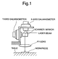
- a laser machining apparatus using a galvanometer performs machining in such a manner that rotational operations of the galvanometer having two axes along X- and Y-directions are controlled by a rotational drive unit, and a workpiece is irradiated with a beam of laser light reflected by mirrors and condensed by an optical unit such as a condenser lens and is worked by being molten and evaporated by the energy of the laser beam, as shown in Fig.1
- This type of laser machining apparatus has a high resolution on the order of microradians and a wide scanning angle, is capable of high-speed operation, and is particularly suitable for use in the field of working for accurately forming fine holes of a size on the order of microns.
- the galvanometer in the laser machining apparatus has a position sensor such as a capacitance sensor for detecting the position of each the mirror.
- the galvanometer is accurately driven at a high speed by feedback control using a sensed position signal from the capacitance sensor.
- the conventional controller for controlling the galvanometer used to perform scanning with a laser beam in laser machining apparatuses is conventionally constituted by analog circuitry elements and therefore has problems described below.
- the adjusted state is changed due to changes with time in analog devices constituting the analog circuit. That is, generally speaking, devices constituting a circuit change with time, and changes with time in the devices are inherently added on a processed signal. For this reason, an error occurs in galvanometer position control.
- a change in the adjusted state of the galvanometer is caused by characteristic changes of analog devices constituting the circuit according to environment temperature change. That is, in a case where temperature of an environment in which the laser machining apparatus is installed may vary largely, a considerable change occurs in the characteristic of the control circuit and therefore frequent galvanometer position adjustment is inherently required according to changes in environment temperature.
- an analog circuit has many adjustment points such as variable resistor adjustments and an increased number of process steps and, therefore, a skilled person for fine adjustments is also required. Accordingly, in the adjustment based on the usage of the analog circuit, a complicated adjustment procedure is required and it becomes difficult for persons other than those experienced in handling the apparatus to perform adjustment operations.
- an object of the present invention is to provide a galvanometer controller capable of controlling a galvanometer with stability and with immunity to changes with time and variation in environment temperature and having improved operability and expandability.
- Another object 'of the present invention is to provide a laser machining apparatus having the galvanometer controller mentioned above.
- a galvanometer controller which controls the direction of laser scanning performed by a galvanometer on each of two axes
- the galvanometer controller comprising a correcting arrangement formed in a digital circuit, further, the correcting arrangement having a distortion correction section for correcting a working distortion of an optical unit including a lens, an orthogonality correction section for correcting the orthogonality between the two axes of the galvanometer, and a linearity correction section for correcting the linearity on each of the two axes.
- the galvanometer controller includes a temperature/humidity detector and characteristic controlling means for controlling a characteristic thereof according to the temperature change or humidity change.
- the laser machining apparatus of Fig. 1 comprises a galvanometer optical unit having an X-axis galvanometer, a Y-axis galvanometer, scanner mirrors, and a f ⁇ lens.
- the laser beam is deflected for scanning by the scanner mirrors attached to the X-axis and Y-axis galvanometers and is condensed by the f ⁇ lens on a workpiece.
- Fig. 2 is a diagram schematically showing the configuration of the galvanometer controller according to the first embodiment of the present invention, and Fig. 3 shows a detail of a part in Fig. 2.
- the laser machining apparatus has a laser beam source (not shown), galvanometer deflectors 6a and 6b which respectively reflect, along X- and Y-axes, the laser beam, position sensors 7a and 7b which respectively detect the positions of the galvanometer deflectors, a galvanometer controller 16 which controls the galvanometer deflectors by referring to the sensed signals from the position sensors, the optical unit which condenses on the workpiece the laser beam reflected by the galvanometer deflectors, and a host controller 1 which controls the galvanometer controller.
- a laser beam source not shown
- galvanometer deflectors 6a and 6b which respectively reflect, along X- and Y-axes, the laser beam
- position sensors 7a and 7b which respectively detect the positions of the galvanometer deflectors
- a galvanometer controller 16 which controls the galvanometer deflectors by referring to the sensed signals from the position sensors
- the optical unit which condenses on the workpiece the laser beam reflected by the gal
- the galvanometer controller 16 is constituted by an input/output port 8 through which a digital position command signal is input from the host controller 1, a digital control unit 2 which performs digital signal processing, D/A converters 3a and 3b which convert galvanometer control outputs from the digital control unit 2 into analog signals, power amplifiers 4a and 4b which amplify outputs from the D/A converters 3a and 3b and drive the galvanometer deflectors 6a and 6b, and A/D converters 5a and 5b which are supplied with output signals from the position sensors 7a and 7b provided on the galvanometer deflectors with the X- and Y-axes, and which convert these analog signals into digital signals.
- the position command and parameters supplied from the host controller 1 are input to the digital control unit 2.
- the sensed signals in analog form from the position sensors 7a and 7b on the galvanometer deflectors 6a and 6b are converted into digital signals by the A/D converters 5a and 5b.
- the converted digital signals are input to the digital control unit 2.
- digital signals for control of the galvanometer deflectors 6a and 6b are output from the digital control unit 2 and are converted into analog signals by the D/A converters 3a and 3b.
- the power amplifiers 4a and 4b amplify the converted analog signals and respectively drive the galvanometer deflectors 6a and 6b by the amplified signals.
- the optical unit scans a surface of the workpiece mounted on a table with laser beam reflected by the galvanometer deflectors 6a and 6b to perform any of various kinds of working such as marking, trimming, boring and welding.
- a distortion correction section 9 corrects a working distortion which occurs when a working lens having optical distortion is used.
- the orthogonality correction section 10 corrects the orthogonality error between the two axes of the galvanometer deflectors 6a and 6b.
- Each of the linearity correction sections 11a and 11b corrects the linearity error on the corresponding axis.
- Blocks 12a and 12b of the next stage are proportional, integral and differential (PID) control blocks and well known in the technical field, in which PID control processing is performed by using the feedback sensed position signals 13a and 13b representing the positions of the galvanometer deflectors 6a and 6b.
- the results of this processing are output as output signals 14a and 14b for control of the galvanometer deflectors 6a and 6b.
- Parameters for each correction processing and the control processing may be rewritten in a parameter table 15 by being supplied from the host controller 1 through the input/output port 8.
- a distortion in the X-axis direction can be corrected by a gain coefficient Ko2 expressed by a second-order function on the Y-axis.
- a distortion in the Y-axis direction can be corrected by a gain coefficient Ko1.
- the following equations are used after actual distortions (errors) ⁇ X and ⁇ Y in the X-axis and Y-axis are detected while the command data of square figure shown in Fig.4 are applied.
- Ko1 ⁇ Y / ( Y i X i 2 )
- Ko2 ⁇ X / ( X i Y i 2 )
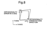
- orthogonal error correction performed in the orthogonality correction section 10 will be described. There are errors of orthogonality with respect to the X- and Y-axes depending on attachment of the X-axis and Y-axis galvanometers, inclination of the scanner mirrors, etc.
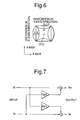
- a digital arithmetic circuit shown in Fig. 7 is applied to correct the orthogonality error.
- Data after orthogonality correction are expressed by Xo and Yo.
- Xi X-axis command data
- Yi Y-axis command data
- linearity correction (mesh correction) will be described. Errors due to variation in accuracy of the galvanometers and distortions in the optical unit influence the working accuracy.
- the linearity correction is intended to correct nonlinear errors which cannot be corrected by either of the above distortion correction and orthogonality correction.
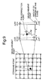
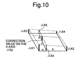
- the linearity correction is performed in such a manner that the amount of error is measured in advance at each of measurement points set in correspondence with meshes, as shown in Fig. 9. In this case, cross points of the meshes correspond to command points which are in advance set to detect the errors ⁇ X1 to ⁇ X4.
- the correction value on the X-axis is computed from amounts of error ⁇ X1 to ⁇ X4 at four points surrounding the command point and from designated position data a to d on the command point, as shown in Fig. 9.
- the correction value on the Y-axis is computed in the same way.
- the circuits for performing processing of various kinds including the processing for correcting a working distortion of a lens, the processing for correcting the orthogonality between the two axes, processing for correcting the linearity on each axis, and the PID control processing using the sensed position signals 13a and 13b as feedback signals, and the management table for storing and managing parameters for each correction processing are provided in the digital control unit 2, thereby making it possible to reduce changes in characteristics due to changes with time in the controller or factors in the operating environment and to thereby control the galvanometer deflectors with stability.
- the parameters for each processing from the host controller 1 operations for adjusting the galvanometer deflectors can be performed more easily and, further, an unskilled operator can easily perform the adjustment operations with reliability.
- Fig. 11 shows a digital control unit 2' of a second embodiment
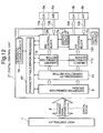
- Fig. 12 shows another configuration of the galvanometer controller of a third embodiment.
- the second embodiment is characterized by performing function of reducing the influence of resonance of galvanometer deflectors.
- the third embodiment is characterized by performing function of automatically optimizing parameters in addition to those according to the first embodiment. In other respects, these embodiments are the same as the first embodiment.
- the digital control unit 2' further includes notch circuits 17a and 17b.
- the digital control unit 2" further includes an automatic turning circuit 18.
- a galvanometer deflector has a specific resonance frequency because of its structural characteristic. If the operating frequency of the galvanometer deflector is close to the resonance frequency, the galvanometer deflector resonates and vibration of a rotating shaft of the deflector occurs, thereby resulting in failure of accurate scanning with a laser beam.
- the notch circuits 17a and 17b are connected to the PID control blocks 12a and 12b to reduce resonating vibration of the galvanometer deflectors.
- the automatic tuning circuit 18 obtains parameters from the parameter table 15 for storing and managing parameters for use in the correction processing and control processing, compares the parameters with values input in advance, performs computation using the parameters, and performs automatic control such that the parameters converge to optimum values.
- the sections for the various kind corrections and the PID control blocks are incorporated in the digital unit, and additional circuits are provided in the unit 2, thereby enabling the galvanometer deflectors to be controlled with higher accuracy while achieving the same effect as that of the first embodiment.
- a fourth embodiment shown in Fig.13 is capable of compensating the characteristic changes of a galvanometer due to the temperature change and humidity change.
- Fig. 13 there are provided a temperature detector 19, a humidity detector 20 and a temperature/humidity converter table 23. The temperature detected signal and humidity detected signal from the detectors 19 and 20 are supplied to the temperature/humidity converter table 23 through A/D converters 21 and 22, respectively.
- a gain factor for the sensed position signal Vp produced in the position sensor 7 is predeterminedly stored.
- the position sensed error due to the temperature change and humidity change are previously measured in practice and after this, the gain factor for compensating the position sensed error is determined and stored in the table.
- the gain factor can be expressed by a functional equation according to the temperature change and humidity change, it may be possible to make up the table 23 by apply at least one function table. Further, when extent of the position sensed error is varied according to the position of the galvanometer, the gain factor is determined according to the sensed position in addition to the temperature and humidity.
- the gain factor data Dg are outputted from the table 23 and applied the position sensor 7 through a D/A converter 24.
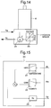
- Fig.14 showing the position sensor 7, an initial position sensed signal level from an angle detector 25 is controlled in response to the gain factor signal Vg from the D/A converter 24.
- Fig.15 showing one example on the temperature/humidity converter table 23
- the temperature data Dt and the humidity data Dw are converted in function tables 27 and 28 and the converted data are multiplied. Further, the multiplied data are corrected by an individual difference factor Ky depending on each galvanometer 6 in a correction circuit 29.
- the galvanometer controller and the laser machining apparatus having the galvanometer controller have advantages described below.
- the adjustment quality can be improved for the same reason as the third advantage.
- change of control software in the digital control unit suffices for enabling addition of a function.
- the facility with which functional expansion is performed is improved and a higher degree of functional expansion can also be performed.
Landscapes
- Physics & Mathematics (AREA)
- Optics & Photonics (AREA)
- Engineering & Computer Science (AREA)
- Plasma & Fusion (AREA)
- Mechanical Engineering (AREA)
- General Physics & Mathematics (AREA)
- Laser Beam Processing (AREA)
- Mechanical Optical Scanning Systems (AREA)
Abstract
Description
To correct the barrel and star distortions, correction processing is performed by a digital arithmetic circuit shown in Fig.5. Data after the distortion correction are expressed by Xo and Yo.
From these equations, a distortion in the X-axis direction can be corrected by a gain coefficient Ko2 expressed by a second-order function on the Y-axis. Also, a distortion in the Y-axis direction can be corrected by a gain coefficient Ko1. As shown in Fig. 6, to seek the coefficients Ko1 and Ko2, the following equations are used after actual distortions (errors) ΔX and ΔY in the X-axis and Y-axis are detected while the command data of square figure shown in Fig.4 are applied.
Claims (8)
- A galvanometer controlling apparatus comprising:a galvanometer for scanning a laser beam;optical unit receiving a scanned laser beam from the galvanometer to lead the scanned laser beam for a workpiece;a position sensor for sensing a scanning position of the galvanometer to deliver a sensed signal;processing means receiving a digital command signal from a upstream stage and the sensed signal from the position sensor for processing the digital command signal with the sensed signal to deliver a digital driving signal for the galvanometer;D/A converter for converting the digital driving signal into an analog signal;an amplifier for amplifying the analog signal and supplying an amplified analog signal to the galvanometer; wherein the processing means includes a correction circuit for correcting scanning performed by the galvanometer, and the correction circuit is formed in a digital circuit.
- A galvanometer controlling apparatus according to claim 1, wherein the correction circuit corrects laser beam scanning caused by optical distortion contained in the optical unit.
- A galvanometer controlling apparatus according to claim 1, wherein the galvanometer has a arrangement for scanning the laser beam on two axes and the correction circuit corrects an error in orthogonality with respect to the two axes.
- A galvanometer controlling apparatus according to claim 1, wherein the galvanometer has a arrangement for scanning the laser beam on two axes and the correction circuit corrects nonlinear errors due to variation in accuracy of the galvanometer.
- A galvanometer controlling apparatus according to any of claims 1 to 4, further comprising a temperature detector to produce a temperature signal, wherein the correction circuit corrects an error due to characteristic change of the galvanometer depending on temperature change, in response to the temperature signal.
- A galvanometer controlling apparatus according to any of claims 1 to 5, further comprising a humidity detector to produce a humidity signal, wherein the correction circuit corrects an error due to characteristic change of the galvanometer depending on humidity change, in response to the humidity signal.
- A laser machining apparatus comprising:a galvanometer for scanning laser beam;a table;optical elements receiving a scanned laser beam from the galvanometer to lead the scanned laser beam for a workpiece on the table;a position sensor for sensing a scanning position of the galvanometer to deliver a sensed signal;processing means receiving command data from a upstream stage and the sensed signal from the position sensor for processing the command data with the sensed signal to deliver driving data for the galvanometer;D/A converter for converting the driving data into an analog signal;an amplifier for amplifying the analog signal and supplying an amplified analog signal to the galvanometer; wherein the processing means includes a correction circuit for correcting scanning performed by the galvanometer, and the correction circuit is formed in a digital circuit.
- Method of controlling comprising one or a plurality of steps corresponding to the features of any of claims 1 to 7.
Applications Claiming Priority (2)
| Application Number | Priority Date | Filing Date | Title |
|---|---|---|---|
| JP2001063332 | 2001-03-07 | ||
| JP2001063332 | 2001-03-07 |
Publications (2)
| Publication Number | Publication Date |
|---|---|
| EP1238745A2 true EP1238745A2 (en) | 2002-09-11 |
| EP1238745A3 EP1238745A3 (en) | 2004-06-30 |
Family
ID=18922344
Family Applications (1)
| Application Number | Title | Priority Date | Filing Date |
|---|---|---|---|
| EP02004385A Withdrawn EP1238745A3 (en) | 2001-03-07 | 2002-03-05 | Galvanometer controller and laser machining apparatus |
Country Status (2)
| Country | Link |
|---|---|
| US (1) | US6674045B2 (en) |
| EP (1) | EP1238745A3 (en) |
Cited By (18)
| Publication number | Priority date | Publication date | Assignee | Title |
|---|---|---|---|---|
| DE10237384A1 (en) * | 2002-08-12 | 2004-03-04 | Zeiss Optronik Gmbh | Scanner and method for operating a scanner |
| DE102005047218A1 (en) * | 2005-10-01 | 2007-04-05 | Carl Zeiss Jena Gmbh | Adjusting method for controller of optical scanner, involves production of transfer function from given target movement whereby optical scanner has beam deflecting element provided for deflecting optical beam |
| DE102005047217A1 (en) * | 2005-10-01 | 2007-04-05 | Carl Zeiss Jena Gmbh | Optical scanner driving method for e.g. laser scanning microscope, involves generating driving signals for optical scanner depending on input signal using scanner parameter for moving illuminating laser beam and detection radiations |
| EP2005238A4 (en) * | 2006-04-07 | 2011-07-06 | Amo Dev Llc | ADAPTIVE PATTERN CORRECTION FOR LASER SCANNING APPARATUSES |
| CN108698164A (en) * | 2016-01-19 | 2018-10-23 | 恩耐公司 | Method for processing calibration data in a 3D laser scanner system |
| US10434600B2 (en) | 2015-11-23 | 2019-10-08 | Nlight, Inc. | Fine-scale temporal control for laser material processing |
| US10520671B2 (en) | 2015-07-08 | 2019-12-31 | Nlight, Inc. | Fiber with depressed central index for increased beam parameter product |
| US10535973B2 (en) | 2015-01-26 | 2020-01-14 | Nlight, Inc. | High-power, single-mode fiber sources |
| CN111006447A (en) * | 2019-12-11 | 2020-04-14 | 重庆科技学院 | Constant temperature and humidity air supply device control system for pharmaceutical equipment |
| US10618131B2 (en) | 2014-06-05 | 2020-04-14 | Nlight, Inc. | Laser patterning skew correction |
| US10656330B2 (en) | 2016-09-29 | 2020-05-19 | Nlight, Inc. | Use of variable beam parameters to control solidification of a material |
| US10673197B2 (en) | 2016-09-29 | 2020-06-02 | Nlight, Inc. | Fiber-based optical modulator |
| US10673198B2 (en) | 2016-09-29 | 2020-06-02 | Nlight, Inc. | Fiber-coupled laser with time varying beam characteristics |
| US10673199B2 (en) | 2016-09-29 | 2020-06-02 | Nlight, Inc. | Fiber-based saturable absorber |
| US10730785B2 (en) | 2016-09-29 | 2020-08-04 | Nlight, Inc. | Optical fiber bending mechanisms |
| US10971884B2 (en) | 2015-03-26 | 2021-04-06 | Nlight, Inc. | Fiber source with cascaded gain stages and/or multimode delivery fiber with low splice loss |
| US11173548B2 (en) | 2017-04-04 | 2021-11-16 | Nlight, Inc. | Optical fiducial generation for galvanometric scanner calibration |
| US11179807B2 (en) | 2015-11-23 | 2021-11-23 | Nlight, Inc. | Fine-scale temporal control for laser material processing |
Families Citing this family (12)
| Publication number | Priority date | Publication date | Assignee | Title |
|---|---|---|---|---|
| EP1680255A4 (en) * | 2003-10-17 | 2008-10-08 | Gsi Lumonics Corp | SOFT SCAN FIELD |
| KR100970241B1 (en) * | 2005-06-07 | 2010-07-16 | 닛산 다나카 가부시키가이샤 | Laser Piercing Method and Processing Equipment |
| CN101286100A (en) * | 2007-04-10 | 2008-10-15 | 鸿富锦精密工业(深圳)有限公司 | Touch screen control device and control method |
| US8426768B2 (en) | 2008-02-20 | 2013-04-23 | Aerotech, Inc. | Position-based laser triggering for scanner |
| US8986497B2 (en) | 2009-12-07 | 2015-03-24 | Ipg Photonics Corporation | Laser lift off systems and methods |
| US9669613B2 (en) * | 2010-12-07 | 2017-06-06 | Ipg Photonics Corporation | Laser lift off systems and methods that overlap irradiation zones to provide multiple pulses of laser irradiation per location at an interface between layers to be separated |
| CN101804521B (en) * | 2010-04-15 | 2014-08-20 | 中国电子科技集团公司第四十五研究所 | Galvanometer system correction device and correction method thereof |
| JP5550525B2 (en) * | 2010-10-29 | 2014-07-16 | ビアメカニクス株式会社 | Galvano scanner and laser processing machine |
| US9808888B2 (en) | 2013-08-05 | 2017-11-07 | Gentex Corporation | Laser system and method thereof |
| JP6457653B2 (en) * | 2015-03-17 | 2019-01-23 | ハンズ レーザー テクノロジー インダストリー グループ カンパニー リミテッド | Laser scanning apparatus and laser scanning system |
| TWM533816U (en) * | 2016-04-06 | 2016-12-11 | Soonmark Co Ltd | Miniature portable engraving laser controller |
| US11305377B2 (en) * | 2019-12-23 | 2022-04-19 | Precitec Gmbh & Co. Kg | Add-on module for interposing between a control device and a laser machining head of a laser machining system |
Family Cites Families (5)
| Publication number | Priority date | Publication date | Assignee | Title |
|---|---|---|---|---|
| US4705996A (en) * | 1986-10-03 | 1987-11-10 | Greyhawk Systems | Apparatus for positioning a rotating element |
| US4800271A (en) * | 1987-06-23 | 1989-01-24 | Canadian Patents & Development Ltd. | Galvanometric optical scanning system having synchronization photodetectors |
| US5187364A (en) * | 1989-03-22 | 1993-02-16 | National Research Council Of Canada/Conseil National De Recherches Du Canada | Scanning device with waveform generator optimizer |
| US5646765A (en) * | 1994-10-05 | 1997-07-08 | Synrad, Inc. | Laser scanner |
| US6483071B1 (en) * | 2000-05-16 | 2002-11-19 | General Scanning Inc. | Method and system for precisely positioning a waist of a material-processing laser beam to process microstructures within a laser-processing site |
-
2002
- 2002-03-05 EP EP02004385A patent/EP1238745A3/en not_active Withdrawn
- 2002-03-06 US US10/090,780 patent/US6674045B2/en not_active Expired - Fee Related
Cited By (32)
| Publication number | Priority date | Publication date | Assignee | Title |
|---|---|---|---|---|
| DE10237384A1 (en) * | 2002-08-12 | 2004-03-04 | Zeiss Optronik Gmbh | Scanner and method for operating a scanner |
| US6850376B2 (en) | 2002-08-12 | 2005-02-01 | Zeiss Optronik Gmbh | Scanner and method for operating a scanner |
| DE102005047218A1 (en) * | 2005-10-01 | 2007-04-05 | Carl Zeiss Jena Gmbh | Adjusting method for controller of optical scanner, involves production of transfer function from given target movement whereby optical scanner has beam deflecting element provided for deflecting optical beam |
| DE102005047217A1 (en) * | 2005-10-01 | 2007-04-05 | Carl Zeiss Jena Gmbh | Optical scanner driving method for e.g. laser scanning microscope, involves generating driving signals for optical scanner depending on input signal using scanner parameter for moving illuminating laser beam and detection radiations |
| DE102005047218B4 (en) | 2005-10-01 | 2021-10-07 | Carl Zeiss Microscopy Gmbh | Method for controlling an optical scanner, optical scanner and laser scanning microscope |
| US8013288B2 (en) | 2005-10-01 | 2011-09-06 | Carl Zeiss Microimaging Gmbh | Method for correcting a control of an optical scanner and the optical scanner |
| EP2005238A4 (en) * | 2006-04-07 | 2011-07-06 | Amo Dev Llc | ADAPTIVE PATTERN CORRECTION FOR LASER SCANNING APPARATUSES |
| AU2007248898B2 (en) * | 2006-04-07 | 2013-09-26 | Amo Development, Llc | Adaptive pattern correction for laser scanners |
| US11465232B2 (en) | 2014-06-05 | 2022-10-11 | Nlight, Inc. | Laser patterning skew correction |
| US10618131B2 (en) | 2014-06-05 | 2020-04-14 | Nlight, Inc. | Laser patterning skew correction |
| US10535973B2 (en) | 2015-01-26 | 2020-01-14 | Nlight, Inc. | High-power, single-mode fiber sources |
| US10916908B2 (en) | 2015-01-26 | 2021-02-09 | Nlight, Inc. | High-power, single-mode fiber sources |
| US10971884B2 (en) | 2015-03-26 | 2021-04-06 | Nlight, Inc. | Fiber source with cascaded gain stages and/or multimode delivery fiber with low splice loss |
| US10520671B2 (en) | 2015-07-08 | 2019-12-31 | Nlight, Inc. | Fiber with depressed central index for increased beam parameter product |
| US11794282B2 (en) | 2015-11-23 | 2023-10-24 | Nlight, Inc. | Fine-scale temporal control for laser material processing |
| US10434600B2 (en) | 2015-11-23 | 2019-10-08 | Nlight, Inc. | Fine-scale temporal control for laser material processing |
| US11331756B2 (en) | 2015-11-23 | 2022-05-17 | Nlight, Inc. | Fine-scale temporal control for laser material processing |
| US11179807B2 (en) | 2015-11-23 | 2021-11-23 | Nlight, Inc. | Fine-scale temporal control for laser material processing |
| EP3389915A4 (en) * | 2016-01-19 | 2018-12-19 | NLIGHT, Inc. | Method of processing calibration data in 3d laser scanner systems |
| CN108698164A (en) * | 2016-01-19 | 2018-10-23 | 恩耐公司 | Method for processing calibration data in a 3D laser scanner system |
| US10739579B2 (en) | 2016-01-19 | 2020-08-11 | Nlight, Inc. | Method of processing calibration data in 3D laser scanner systems |
| US10295820B2 (en) | 2016-01-19 | 2019-05-21 | Nlight, Inc. | Method of processing calibration data in 3D laser scanner systems |
| US10730785B2 (en) | 2016-09-29 | 2020-08-04 | Nlight, Inc. | Optical fiber bending mechanisms |
| US10673198B2 (en) | 2016-09-29 | 2020-06-02 | Nlight, Inc. | Fiber-coupled laser with time varying beam characteristics |
| US10673197B2 (en) | 2016-09-29 | 2020-06-02 | Nlight, Inc. | Fiber-based optical modulator |
| US10663767B2 (en) | 2016-09-29 | 2020-05-26 | Nlight, Inc. | Adjustable beam characteristics |
| US10673199B2 (en) | 2016-09-29 | 2020-06-02 | Nlight, Inc. | Fiber-based saturable absorber |
| US10656330B2 (en) | 2016-09-29 | 2020-05-19 | Nlight, Inc. | Use of variable beam parameters to control solidification of a material |
| US11173548B2 (en) | 2017-04-04 | 2021-11-16 | Nlight, Inc. | Optical fiducial generation for galvanometric scanner calibration |
| US12591144B2 (en) | 2017-04-04 | 2026-03-31 | Nlight, Inc. | Optical fiducial generation for galvanometric scanner calibration |
| CN111006447B (en) * | 2019-12-11 | 2021-10-26 | 重庆科技学院 | Constant temperature and humidity air supply device control system for pharmaceutical equipment |
| CN111006447A (en) * | 2019-12-11 | 2020-04-14 | 重庆科技学院 | Constant temperature and humidity air supply device control system for pharmaceutical equipment |
Also Published As
| Publication number | Publication date |
|---|---|
| EP1238745A3 (en) | 2004-06-30 |
| US20020125222A1 (en) | 2002-09-12 |
| US6674045B2 (en) | 2004-01-06 |
Similar Documents
| Publication | Publication Date | Title |
|---|---|---|
| US6674045B2 (en) | Galvanometer controller and laser machining apparatus | |
| IL105188A (en) | Scanner | |
| KR20040005990A (en) | Laser beam positioning device for laser machining, apparatus | |
| EP0812264B1 (en) | Method and apparatus for generating engraving signals | |
| US6025688A (en) | Alignment apparatus | |
| US7270270B2 (en) | Optical scanner control method, optical scanner and laser machining apparatus | |
| US8780406B2 (en) | Method for creating drive pattern for galvano-scanner system | |
| US6954265B2 (en) | Method, apparatus and system for aligning an optical fiber end with an optical waveguide | |
| DE102019130645A1 (en) | ADAPTIVE AND CONTEX-AWARENESS MICROELECTROMECHANICAL SYSTEM (MEMS) MIRROR CONTROL | |
| US4686359A (en) | Picture scanning and recording using a photoelectric focusing system | |
| US8054521B2 (en) | Method for adjusting galvano scanner system | |
| JP3614680B2 (en) | Laser processing method and apparatus | |
| JP2002333594A (en) | Galvanometer controller and laser beam machining apparatus | |
| US9718146B2 (en) | System and method for calibrating laser processing machines | |
| CN116021178A (en) | Systems and methods for measuring and calibrating laser processing machines with low power beam profilers | |
| KR20190045817A (en) | Control Device of Laser Processing Apparatus, Laser Processing Method, and Laser Processing Apparatus | |
| JPH01278987A (en) | Adjusting device for optical axis | |
| JP2000098271A (en) | Galvano-mirror drive device | |
| JPH08321274A (en) | Active vibration isolation device for electron microscope | |
| JP4580600B2 (en) | Galvano scanner control method, apparatus, and galvano scanner | |
| JPH05115992A (en) | Laser beam machine | |
| JP2003215492A (en) | Galvanometer controller and laser processing apparatus | |
| JP4818626B2 (en) | Laser processing apparatus and notch filter setting method | |
| JP2630025B2 (en) | Laser trimming method and apparatus | |
| JPH05173639A (en) | Position control device and control method thereof |
Legal Events
| Date | Code | Title | Description |
|---|---|---|---|
| PUAI | Public reference made under article 153(3) epc to a published international application that has entered the european phase |
Free format text: ORIGINAL CODE: 0009012 |
|
| AK | Designated contracting states |
Kind code of ref document: A2 Designated state(s): AT BE CH CY DE DK ES FI FR GB GR IE IT LI LU MC NL PT SE TR |
|
| AX | Request for extension of the european patent |
Free format text: AL;LT;LV;MK;RO;SI |
|
| PUAL | Search report despatched |
Free format text: ORIGINAL CODE: 0009013 |
|
| AK | Designated contracting states |
Kind code of ref document: A3 Designated state(s): AT BE CH CY DE DK ES FI FR GB GR IE IT LI LU MC NL PT SE TR |
|
| AX | Request for extension of the european patent |
Extension state: AL LT LV MK RO SI |
|
| RIC1 | Information provided on ipc code assigned before grant |
Ipc: 7G 01R 5/00 B Ipc: 7B 23K 26/10 B Ipc: 7B 23K 26/04 A |
|
| RAP1 | Party data changed (applicant data changed or rights of an application transferred) |
Owner name: LASERFRONT TECHNOLOGIES, INC. |
|
| 17P | Request for examination filed |
Effective date: 20040526 |
|
| AKX | Designation fees paid |
Designated state(s): DE FR GB |
|
| STAA | Information on the status of an ep patent application or granted ep patent |
Free format text: STATUS: THE APPLICATION IS DEEMED TO BE WITHDRAWN |
|
| 18D | Application deemed to be withdrawn |
Effective date: 20060509 |