EP1238579B1 - Mittel zur Messung der Schnittbreite von Erntegut - Google Patents
Mittel zur Messung der Schnittbreite von Erntegut Download PDFInfo
- Publication number
- EP1238579B1 EP1238579B1 EP01105749A EP01105749A EP1238579B1 EP 1238579 B1 EP1238579 B1 EP 1238579B1 EP 01105749 A EP01105749 A EP 01105749A EP 01105749 A EP01105749 A EP 01105749A EP 1238579 B1 EP1238579 B1 EP 1238579B1
- Authority
- EP
- European Patent Office
- Prior art keywords
- crop
- width
- agricultural machine
- processor
- measuring means
- Prior art date
- Legal status (The legal status is an assumption and is not a legal conclusion. Google has not performed a legal analysis and makes no representation as to the accuracy of the status listed.)
- Expired - Lifetime
Links
Images


Classifications
-
- A—HUMAN NECESSITIES
- A01—AGRICULTURE; FORESTRY; ANIMAL HUSBANDRY; HUNTING; TRAPPING; FISHING
- A01D—HARVESTING; MOWING
- A01D41/00—Combines, i.e. harvesters or mowers combined with threshing devices
- A01D41/12—Details of combines
- A01D41/127—Control or measuring arrangements specially adapted for combines
Definitions
- the invention refers to an agricultural machine according to the precharacterizing part of claim 1.
- Crop management decisions are increasingly based on the information presented in yield maps. Thus, it is important that they are accurate and contain as few errors as possible.
- two systematic errors occur in existing methods of producing yield maps caused by difficulties in defining the start and end of cutting and knowing the crop width entering the agricultural implement, as a combine.
- In order to produce error-free yield maps it is necessary to have an accurate and reliable method of detecting the start and end of harvesting and the width of newly harvested material entering the agricultural harvester.
- buttons that allow the operator to record the proportional width of the header being full of crop. If the operator does not use these buttons consistently and accurate, then it will cause further errors (S. Blackmore and M. Moore, Remedial Correction of Yield Map Data, Precision Agriculture, 1999, Kluwer, Vol. 1, pages 53-66).
- EP 0 960 558 A a method for generating yield maps is proposed, in which the presence of crop to be harvested in front of a header is indicated by a sensor monitoring the position of the reel on the combine's header. Additionally, ultrasonic distance sensors measure the width of the harvested crop swath. Thus, on both side ends of the header, ultrasonic distance sensors submit ultrasonic waves to the swath, and the swath width is determined based on the run time of the ultrasonic waves. This method is not working reliably when two swaths with a space between them are taken up. The ultrasonic sensors do not work when the crop is lodged.
- DE 195 43 343 A discloses a baler in which the volume of received crop is measured by a capacitive sensor.
- DE 40 41 995 A proposes a forage harvester in which presence of crop throughput is detected by means of a capacitive sensor. According to the signal of the sensor, the rotational speed of the chopping drum of the forage harvester is controlled, or conservation chemicals are added to the harvested crop.
- the monitor comprises a number of material presence sensors distributed over the width of the harvesting machine in the range the crop is harvested.
- the effective width of the received material is obtained by adding the signals of the respective sensors.
- the effective width is multiplied with the signal from a path sensor in order to obtain information on the total harvested area.
- the object of the present invention is to provide an apparatus for establishing a yield map having an improved precision and reliability.
- a number of crop presence sensors are distributed over the width of a crop receiving and/or processing means of the agricultural machine.
- the crop presence sensors are evenly distributed of the width. It would also be possible to have an uneven distribution.
- Each one of the crop presence sensors is capable of detecting whether crop is present in its detection range.
- the size of the detection range depends on the type of the crop presence sensor. It is possible to use crop presence sensors having a relatively large detection range, as ultrasonic sensors covering a part of the width of the crop receiving means, or to use crop presence sensors with a relatively small detection range. The latter only detect crop passing in their vicinity.
- the crop width measuring means is operable to establish an information regarding the width of the-crop actually being taken up or processed (e.g. mown).
- the established swath width can be calculated by adding the width of the detection ranges of the crop presence sensors detecting crop (when the detection range is relatively large), or by multiplying the distance between adjacent sensors with the number of sensors detecting crop.
- the crop width measuring means according to the present invention is capable of detecting when two swaths with a gap between them are received.
- the invention teaches to arrange the crop presence sensor such that moving crop removes (wipes) any stationary crop away from the crop presence sensor. This is achieved by locating the outer surface of the crop presence sensor in the plane of the surface of the crop receiving and/or processing means. When the latter is a header of a combine or forage harvester, the outer surface of the crop presence sensor thus lies within the plane of the bed of the header's table.
- the signal from the crop presence sensor can be electronically processed by means of a signal processor to remove the effect of any stationary crop actuating the crop presence sensor.
- the output signal of the crop presence sensor can be time differentiated and afterwards submitted to a comparator or Schmidt-Trigger.
- Capacitive sensors are preferably used as relatively cheap and compact crop presence sensors having a small detection range. They also work in conditions when crop is lodged.
- the crop width measuring means according to the invention can be used in an apparatus for collecting data concerning crop received and/or processed by an agricultural machine.
- a harvest data generation apparatus comprises a location and/or distance measuring means, as a GPS sensor and/or a speed sensor.
- a processor connected to the location and/or distance measuring means and to the crop width measuring means is provided for processing data.
- only the area from which crop is received or harvested is established by the processor.
- an information regarding the swath width is necessary.
- the swath width sensor of the present invention establishes this information.
- the apparatus for collecting data is operable to establish a yield map.
- a parameter measuring means for measuring a parameter of the received and/or processed crop (as weight per time or moisture) is delivering data to the processor. From these data, the processor establishes a map representative of a variable derived from the parameter at several locations of the field.
- This variable can be the weight of the received crop per area, which is calculated according to the measured received weight per time, the swath width and the speed or position. The area is calculated using the signals from the crop width measuring means. Hence, errors in the yield map due to unknown swath width - as described above - are avoided.
- the signals from the crop presence sensor can also be used to determine whether crop is received at all, and thus yields an information defining the start and end of cutting.
- An accurate definition of cutting is as important as measuring crop width in producing an accurate yield map. Unless at least one crop presence sensor indicates the presence of crop, the yield established by the processor is considered as zero.
- the invention can be used in any type of crop receiving and/or processing machine. Preferably, it is used on a combine, wherein the crop presence sensors are distributed over the active width of a cutter bar of a header of the combine. It could also be used in a forage harvester, the sensors distributed over the width of a corn header. Use of the invention on mowers and any other agricultural machine processing, receiving, taking up or harvesting crop is possible.
- Figure 1 shows an agricultural combine 10 with a chassis 12 and running wheels 14 supporting it on the ground.
- a header 16 is used to take up crop and to conduct it to a feederhouse 18.
- the crop is conducted by the feederhouse 18 to a beater 20.
- the beater 20 guides the crop upward through an intake transition region 22 to a rotary thresher and separator 24.
- a rotary thresher and separator 24 guides the crop upward through an intake transition region 22 to a rotary thresher and separator 24.
- the rotary thresher and separator 24 comprises a rotor housing 26 and a rotor 28 arranged in the rotor housing 26.
- the harvested crop enters the rotor housing 26 through the intake transition region 22.
- the rotary thresher and separator 24 threshes and separates the harvested crop. Grain and chaff fall through grates at the bottom of the rotor housing into a cleaning system 34.
- the cleaning system 34 removes the chaff and conducts the clean grain to a grain elevator 36 which conducts it in turn to a distributing screw conveyor 38.
- the distributing screw conveyor 38 deposits the clean grain in a grain tank 40.
- the clean grain in the grain tank 40 can be unloaded through an unloading screw conveyor 42 into a trailer or truck.
- Threshed straw separated from the grain is conducted out of the rotary thresher and separator 24 through an outlet to a discharge beater 46.
- the discharge beater 46 ejects the straw at the rear end of the combine
- the operation of the combine 10 is controlled from an operator's cab 48.
- a receiver 50 for the reception of GPS signals (global positioning system) is attached above the operator's cab 48.
- GPS signals global positioning system
- a speed sensor measuring the speed of the wheels 14 can be provided.
- Mounted on one side of the grain elevator 36 is a measurement capacitor 52 for measuring the moisture of the grain.
- a flow sensor 54 is located at the outlet of the grain elevator 36.
- the flow sensor 54 comprises an impeller plate mounted for rotation about a horizontal axis. Its deflection depends on the mass flow rate of the harvested crop. The deflection of the impeller plate is measured and thus data on the mass flow rate of the harvested grain is provided.
- Such a sensor is described in EP 0 853 234 A and the documents recited therein.
- a processor 56 located in the operator's cab 48 (or somewhere else on the combine 10) is connected to the GPS receiver 50, the measurement capacitor 52, the flow sensor 54, and the speed sensor, when present.
- the processor 56 is provided with an internal clock or receives external time signals, for example from the receiver 50.
- the processor 56 records the amount of harvested grain (measured by means of the flow sensor 54) and its moisture (measured by means of the measurement capacitor 52) dependent on the geographical position of the combine 10 (measured by means of the GPS receiver 50).
- the processor 56 logs the data and produces a field summary. Thus, it is possible to create a yield map with the logged data, whereby other software is used.
- the header 16 is provided with a swath width sensing arrangement as shown in figure 2.
- the swath width sensing arrangement is submitting data to the processor 56, preferably by means of a bus, cables, optical fibres or electromagnetic waves.
- the processor 56 thus considers when the swath of harvested crop is narrower than the active width of the header 16, what might happen at an end of a field, or when the combine 10 passes certain parts of a field a second time.
- the processor 56 is capable of calculating a correct yield, since the latter depends on the amount of harvested grain and on the area on which it was harvested. This area depends on the swath width measured by the swath width sensing arrangement.
- the header 16 comprises between its side sheets a cutter bar 58 for cutting the crop and an auger 60 for feeding the cut crop to the centre of header 16, where the crop is fed into the feederhouse 18.
- crop dividers 62 are located at the front end of the side sheets 60.
- the dividers 62 are driven into the crop for splitting the crop sideways in front of the header 16 before it is cut by the cutter bar 58.
- the latter defines the active width of the header.
- a conventional reel is usually located above the cutter bar 58.
- a number of crop presence sensors 64 for detecting the presence of crop are distributed of the width of the header 16.
- the crop presence sensors 64 submit data containing an information whether crop is in their detection range (or not) to the processor 56.
- six crop presence sensors 64 are evenly distributed over the active width of the header 16.
- a swath of crop to be harvested is indicated with reference numeral 66. Since in figure 2 the two uppermost crop presence sensors 64 (the most left sensors in the forward moving direction of the header 16) are not within the swath width, they will provide the processor 56 with a signal indicating the lack of crop.
- the three crop presence sensors 64 shown in figure 2 below the two uppermost crop presence sensors 64 are within the swath width. Thus, they submit a signal to the processor 56 indicating that crop is presently harvested at their location. Finally, the lowermost crop presence sensor 64 shown at the bottom of figure 2 (the most right sensor in the forward moving direction of the header 16) is outside the swath width, as well, and submits a corresponding signal to the processor 56.
- the crop presence sensors 64 distributed over the active width of the header 16 thus provide an information on the width of the harvested swath to the processor 56.
- the processor 56 is operable to determine the width of the swath 66.
- the processor 56 is also operable to detect whether harvesting is performed and thus crop is received at a11 (when at least one crop presence sensor 64 gives an information that crop is present) or not (when no crop presence sensor 64 submits data indicating that crop is present).
- a sensor for detecting the location of a reel is superfluous, and disadvantages of such sensors, as inaccuracy, are avoided.
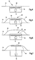
- FIG 3 a vertical cross sectional view of the header 16 is given.
- a crop presence sensor 64 is located at the rear end of the bed 74 of the table of the header 16, and embedded into the surface of the bed 74.
- An alternative position of a crop presence sensor is indicated with 64'; this crop presence sensor 76 is embedded into a stone ridge 76 at the forward end of the bed 74, behind the knives 58.
- the crop presence sensors 64 are capacitive sensors. Such sensors are available from Carlo Gavazzi Industri A/S, Over Hadstenvej 38, 8370 Hadsten, Denmark, order number EC 5525PPAP.
- An embodiment of a capacitive crop presence sensor 64 is shown in more detail in figure 4.
- the crop presence sensor 64 is embedded into the upper surface of the table of the header 16.
- the crop presence sensor 64 comprises a conductive foil 70 or plate mounted below an insulating (but not necessarily transparent) window 68 lying in the plane of the upper surface of the bed 74 of the table of the header 16.
- the foil 70 is electrically connected to a signal processor 72. When crop is present above the window 68, the electric capacity of the foil 70 measured against the header alters (increases).
- the signal processor 72 measures the electric capacity of foil 70.
- the foil 70 is part of an electric resonance circuit, the resonance frequency of which is measured. Any other measurement of the capacity is possible, as well.
- the signal processor 72 thus provides an information regarding the presence of crop in the crop presence sensor's 64 vicinity to the processor 56.
- the crop presence sensor 64 is positioned on the bed 74 of the table of the header 16. Hence crop remaining on the window 68 is normally wiped away by passing crop.
- the output of the signal processor 72 is electrically processed removing the effect of any stationary material actuating the crop presence sensors 64. Thus, a time derivation of a value representing the capacity of foil 70 can be obtained and further processed.
- FIG 5 another embodiment of a capacitive crop presence sensor 64 is given. It is located above the surface 74 of the table of the header. A ramp 78 in forward direction before and behind the crop presence sensor 64 keeps the surface of the crop presence sensor free of stationary material.
- Figure 6 shows a third embodiment of a crop presence sensor 64, located below the stone ridge 76
- figure 7 represents a fourth embodiment of a crop presence sensor 64, integrated into the stone ridge 76, like the crop presence sensor 64' in figure 3.
- the elements of the crop presence sensors 64 of figures 5 to 7 are the same as those of the sensor shown in figure 4.
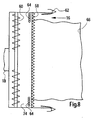
- FIG. 8 For either position 64 or 64' shown in figure 3, it is possible to make use of separate crop presence sensors 64 as indicated in figure 2.
- two arrays of crop presence sensors 64 are provided.
- a first array of crop presence sensors 64 is placed at the left-hand edge of the table.
- a second (optional) array of crop presence sensors 64 is placed against the right-hand end of the table.
- This arrangement of sensors operates like the one disclosed in figure 2, except when the swath width does not cover the sensor array or arrays the processor 56 records the width as zero.
- Both arrays of crop presence sensors 64 preferably cover a width of 0,2 to 1 m.
- Software is used to insert the missing data on the yield map by interpreting between adjacent runs where the table was nearly full. Thus, the yield is known more accurately than with the embodiment of figure 2, although a similar number of crop sensors 64 is used.
Landscapes
- Life Sciences & Earth Sciences (AREA)
- Environmental Sciences (AREA)
- Guiding Agricultural Machines (AREA)
- Combines (AREA)
- Management, Administration, Business Operations System, And Electronic Commerce (AREA)
- Harvester Elements (AREA)
Claims (8)
- Landwirtschaftliche Maschine mit einem Erntegutannahme- und/oder -verarbeitungsmittel, das eingerichtet ist, Erntegut anzunehmen und/oder zu verarbeiten, wobei die Maschine ein Erntegutbreitenmessmittel zur Messung der Breite vom Erntegutannahme- und/oder -verarbeitungsmittel angenommenen und/oder verarbeiteten Ernteguts umfasst, wobei das Erntegutbreitenmessmittel zumindest zwei Erntegutvorhandenseinssensoren (64) mit einem Nachweisbereich umfasst, die Daten bereitstellen, die eine Information darüber enthalten, ob sich Erntegut in ihrem Nachweisbereich befindet, wobei eine Vielzahl von Erntegutvorhandenseinssensoren (64) über die Breite der Erntegutannahme- und/oder -verarbeitungsmittel der landwirtschaftlichen Maschine verteilt sind, dadurch gekennzeichnet, dass die Erntegutvorhandenseinssensoren (64) in der Ebene der Oberfläche der Erntegutannahme- und/oder -verarbeitungsmittel angeordnet sind, so dass bewegendes Erntegut jegliches stationäre Erntegut von den Erntegutvorhandenseinssensoren (64) entfernt.
- Landwirtschaftliche Maschine nach Anspruch 1, dadurch gekennzeichnet, dass sie ein Vorsatz ist.
- Landwirtschaftliche Maschine nach Anspruch 1 oder 2, dadurch gekennzeichnet, dass zumindest ein Erntegutvorhandenseinssensor (64) mit einem Signalprozessor (72) verbunden ist, der das Signal vom Erntegutvorhandenseinssensor (64) elektronisch verarbeitet, wobei der Effekt jeglichen stationären Ernteguts beseitigt wird, der den Erntegutvorhandenseinssensor (64) betätigt.
- Landwirtschaftliche Maschine nach einem der Ansprüche 1 bis 3, dadurch gekennzeichnet, dass wenigstens einer der Erntegutvorhandenseinssensoren (64) ein kapazitiver Sensor ist.
- Landwirtschaftliche Maschine nach einem der Ansprüche 1 bis 4 in Kombination mit einem Gerät zur Sammlung von Daten, die durch die landwirtschaftliche Maschine angenommenes und/oder verarbeitetes Erntegut betreffen, wobei das Gerät zur Sammlung von Daten ein Orts- und/oder Entfernungsmessgerät zur Überwachung der geografischen Position der landwirtschaftlichen Maschine auf einem Feld und/oder die von der Maschine abgedeckten Entfernung, ein Erntegutbreitenmessmittel zur Messung der Breite des von der landwirtschaftlichen Maschine angenommenen und/oder verarbeiteten Ernteguts und einen Prozessor (56) umfasst, der Daten vom Orts- und/oder Entfernungsmessgerät und vom Erntegutbreitenmessmittel annimmt, wobei der Prozessor (56) betreibbar ist, einen Wert zu ermitteln, der von der Fläche abhängt, von der Erntegut angenommen und/oder verarbeitet wurde.
- Landwirtschaftliche Maschine nach Anspruch 5 , dadurch gekennzeichnet, dass sie ein Parametermessmittel zur Messung eines Parameters des angenommenen Ernteguts umfasst und dass der Prozessor (56) betreibbar ist, eine Karte zu erzeugen, die eine vom Parameter an mehreren Stellen des Felds abgeleitete Variable repräsentiert.
- Landwirtschaftliche Maschine nach Anspruch 5 oder 6, dadurch gekennzeichnet, dass der Prozessor (56) anhand des Signals des Erntegutvorhandenseinssensors (64) feststellt, ob überhaupt Erntegut angenommen und/oder Schneiden durchgeführt wird.
- Landwirtschaftliche Maschine nach einem der Ansprüche 5 bis 7, dadurch gekennzeichnet, dass die landwirtschaftliche Maschine ein Mähdrescher ist und dass die Erntegutvorhandenseinssensoren (64) über die Breite eines Schneidbalkens (58) eines Vorsatzes (16) des Mähdreschers verteilt sind.
Priority Applications (8)
| Application Number | Priority Date | Filing Date | Title |
|---|---|---|---|
| EP01105749A EP1238579B1 (de) | 2001-03-08 | 2001-03-08 | Mittel zur Messung der Schnittbreite von Erntegut |
| DE60118518T DE60118518T2 (de) | 2001-03-08 | 2001-03-08 | Mittel zur Messung der Schnittbreite von Erntegut |
| AT01105749T ATE322151T1 (de) | 2001-03-08 | 2001-03-08 | Mittel zur messung der schnittbreite von erntegut |
| US10/090,233 US6668223B2 (en) | 2001-03-08 | 2002-03-04 | Crop width measuring apparatus |
| CA002375009A CA2375009C (en) | 2001-03-08 | 2002-03-07 | Crop width measuring apparatus |
| AU21289/02A AU784164B2 (en) | 2001-03-08 | 2002-03-07 | Crop width measuring apparatus |
| ARP020100847A AR033432A1 (es) | 2001-03-08 | 2002-03-08 | Aparato medidor de ancho de cultivo |
| BRPI0200716-9A BR0200716B1 (pt) | 2001-03-08 | 2002-03-08 | conjunto de medição de largura de uma safra. |
Applications Claiming Priority (1)
| Application Number | Priority Date | Filing Date | Title |
|---|---|---|---|
| EP01105749A EP1238579B1 (de) | 2001-03-08 | 2001-03-08 | Mittel zur Messung der Schnittbreite von Erntegut |
Publications (2)
| Publication Number | Publication Date |
|---|---|
| EP1238579A1 EP1238579A1 (de) | 2002-09-11 |
| EP1238579B1 true EP1238579B1 (de) | 2006-04-05 |
Family
ID=8176717
Family Applications (1)
| Application Number | Title | Priority Date | Filing Date |
|---|---|---|---|
| EP01105749A Expired - Lifetime EP1238579B1 (de) | 2001-03-08 | 2001-03-08 | Mittel zur Messung der Schnittbreite von Erntegut |
Country Status (8)
| Country | Link |
|---|---|
| US (1) | US6668223B2 (de) |
| EP (1) | EP1238579B1 (de) |
| AR (1) | AR033432A1 (de) |
| AT (1) | ATE322151T1 (de) |
| AU (1) | AU784164B2 (de) |
| BR (1) | BR0200716B1 (de) |
| CA (1) | CA2375009C (de) |
| DE (1) | DE60118518T2 (de) |
Families Citing this family (64)
| Publication number | Priority date | Publication date | Assignee | Title |
|---|---|---|---|---|
| GB0028665D0 (en) * | 2000-11-24 | 2001-01-10 | Ford New Holland Nv | A method of estimating crop yields |
| DE102008032191A1 (de) * | 2008-07-09 | 2010-01-14 | Claas Selbstfahrende Erntemaschinen Gmbh | Selbstfahrende Erntemaschine |
| EP2529610A1 (de) * | 2011-05-30 | 2012-12-05 | Agri-Esprit SAS | Verfahren zur Ernteüberwachung |
| US9322629B2 (en) * | 2011-11-22 | 2016-04-26 | Precision Planting Llc | Stalk sensor apparatus, systems, and methods |
| US9693503B2 (en) | 2013-02-20 | 2017-07-04 | Deere & Company | Crop sensing |
| US10178828B2 (en) * | 2013-02-20 | 2019-01-15 | Deere & Company | Per plant crop sensing resolution |
| US11212962B2 (en) | 2013-02-20 | 2022-01-04 | Deere & Company | Field condition determination |
| US9282693B2 (en) | 2013-02-20 | 2016-03-15 | Deere & Company | Data encoding with planting attributes |
| US9066465B2 (en) | 2013-02-20 | 2015-06-30 | Deere & Company | Soil compaction reduction system and method |
| US9668420B2 (en) * | 2013-02-20 | 2017-06-06 | Deere & Company | Crop sensing display |
| CN103115592B (zh) * | 2013-03-01 | 2016-03-30 | 潍坊市计量测试所 | 超声波收获机计亩器 |
| BE1021107B1 (nl) * | 2013-10-28 | 2016-01-18 | Cnh Industrial Belgium Nv | Zwadsensor voor veldhakselaar |
| US10225984B2 (en) * | 2014-03-06 | 2019-03-12 | Raven Industries, Inc. | System and method for sensing an edge |
| US9317979B2 (en) | 2014-05-01 | 2016-04-19 | Deere & Company | Crop density map using row sensors |
| US9903979B2 (en) * | 2014-09-23 | 2018-02-27 | Deere & Company | Yield estimation |
| US10126282B2 (en) | 2014-09-23 | 2018-11-13 | Deere & Company | Yield estimation |
| CN105052369B (zh) * | 2015-08-13 | 2017-05-31 | 江苏农牧科技职业学院 | 联合收获机固体颗粒预收集装置的控制方法 |
| US10188037B2 (en) | 2015-09-24 | 2019-01-29 | Deere & Company | Yield estimation |
| US10858801B2 (en) * | 2017-11-30 | 2020-12-08 | Caterpillar Inc. | System for controlling operation of a machine |
| JP2019170315A (ja) * | 2018-03-29 | 2019-10-10 | 株式会社クボタ | コンバイン |
| US11064653B2 (en) | 2018-06-18 | 2021-07-20 | Ag Leader Technology | Agricultural systems having stalk sensors and data visualization systems and related devices and methods |
| US11419261B2 (en) * | 2018-06-25 | 2022-08-23 | Deere & Company | Prescription cover crop seeding with combine |
| US11589509B2 (en) | 2018-10-26 | 2023-02-28 | Deere & Company | Predictive machine characteristic map generation and control system |
| US11672203B2 (en) | 2018-10-26 | 2023-06-13 | Deere & Company | Predictive map generation and control |
| US11957072B2 (en) | 2020-02-06 | 2024-04-16 | Deere & Company | Pre-emergence weed detection and mitigation system |
| US11641800B2 (en) | 2020-02-06 | 2023-05-09 | Deere & Company | Agricultural harvesting machine with pre-emergence weed detection and mitigation system |
| US11240961B2 (en) | 2018-10-26 | 2022-02-08 | Deere & Company | Controlling a harvesting machine based on a geo-spatial representation indicating where the harvesting machine is likely to reach capacity |
| US11178818B2 (en) | 2018-10-26 | 2021-11-23 | Deere & Company | Harvesting machine control system with fill level processing based on yield data |
| US11653588B2 (en) | 2018-10-26 | 2023-05-23 | Deere & Company | Yield map generation and control system |
| US11079725B2 (en) | 2019-04-10 | 2021-08-03 | Deere & Company | Machine control using real-time model |
| US11467605B2 (en) | 2019-04-10 | 2022-10-11 | Deere & Company | Zonal machine control |
| US11399462B2 (en) | 2018-10-31 | 2022-08-02 | Cnh Industrial America Llc | System and method for calibrating alignment of work vehicles |
| US10966369B2 (en) | 2018-10-31 | 2021-04-06 | Cnh Industrial America Llc | System and method for calibrating alignment of work vehicles |
| JP7174489B2 (ja) * | 2018-12-21 | 2022-11-17 | 株式会社クボタ | コンバイン |
| CN209605915U (zh) * | 2018-12-28 | 2019-11-08 | 厦门帮众科技有限公司 | 一种精确计量装置 |
| US11297768B2 (en) | 2019-02-25 | 2022-04-12 | Ag Leader Technology | Vision based stalk sensors and associated systems and methods |
| US11234366B2 (en) | 2019-04-10 | 2022-02-01 | Deere & Company | Image selection for machine control |
| US20210329838A1 (en) * | 2019-09-04 | 2021-10-28 | Ag Leader Technology | Apparatus, Systems And Methods For Stalk Sensing |
| US11477940B2 (en) | 2020-03-26 | 2022-10-25 | Deere & Company | Mobile work machine control based on zone parameter modification |
| US11659787B2 (en) * | 2020-04-03 | 2023-05-30 | Cnh Industrial America Llc | Harvesting head reel-crop engagement |
| US20210315160A1 (en) | 2020-04-08 | 2021-10-14 | Ag Leader Technology | Devices, Systems, And Methods For Corn Headers |
| US11678607B2 (en) | 2020-07-01 | 2023-06-20 | Ag Leader Technology | Apparatus, systems and methods for eliminating cross-track error |
| US11889788B2 (en) | 2020-10-09 | 2024-02-06 | Deere & Company | Predictive biomass map generation and control |
| US11927459B2 (en) | 2020-10-09 | 2024-03-12 | Deere & Company | Machine control using a predictive map |
| US11650587B2 (en) | 2020-10-09 | 2023-05-16 | Deere & Company | Predictive power map generation and control system |
| US11874669B2 (en) | 2020-10-09 | 2024-01-16 | Deere & Company | Map generation and control system |
| US11592822B2 (en) | 2020-10-09 | 2023-02-28 | Deere & Company | Machine control using a predictive map |
| US11849671B2 (en) | 2020-10-09 | 2023-12-26 | Deere & Company | Crop state map generation and control system |
| US11844311B2 (en) | 2020-10-09 | 2023-12-19 | Deere & Company | Machine control using a predictive map |
| US11825768B2 (en) | 2020-10-09 | 2023-11-28 | Deere & Company | Machine control using a predictive map |
| US11675354B2 (en) | 2020-10-09 | 2023-06-13 | Deere & Company | Machine control using a predictive map |
| US11864483B2 (en) | 2020-10-09 | 2024-01-09 | Deere & Company | Predictive map generation and control system |
| US11946747B2 (en) | 2020-10-09 | 2024-04-02 | Deere & Company | Crop constituent map generation and control system |
| US11727680B2 (en) | 2020-10-09 | 2023-08-15 | Deere & Company | Predictive map generation based on seeding characteristics and control |
| US11845449B2 (en) | 2020-10-09 | 2023-12-19 | Deere & Company | Map generation and control system |
| US11635765B2 (en) | 2020-10-09 | 2023-04-25 | Deere & Company | Crop state map generation and control system |
| US11849672B2 (en) | 2020-10-09 | 2023-12-26 | Deere & Company | Machine control using a predictive map |
| US11871697B2 (en) | 2020-10-09 | 2024-01-16 | Deere & Company | Crop moisture map generation and control system |
| US11895948B2 (en) | 2020-10-09 | 2024-02-13 | Deere & Company | Predictive map generation and control based on soil properties |
| US11474523B2 (en) | 2020-10-09 | 2022-10-18 | Deere & Company | Machine control using a predictive speed map |
| US11711995B2 (en) | 2020-10-09 | 2023-08-01 | Deere & Company | Machine control using a predictive map |
| US11983009B2 (en) | 2020-10-09 | 2024-05-14 | Deere & Company | Map generation and control system |
| US11889787B2 (en) | 2020-10-09 | 2024-02-06 | Deere & Company | Predictive speed map generation and control system |
| US20220210974A1 (en) * | 2021-01-05 | 2022-07-07 | Cnh Industrial America Llc | Mower-conditioner machine for sensing moisture content of crop material |
Family Cites Families (12)
| Publication number | Priority date | Publication date | Assignee | Title |
|---|---|---|---|---|
| SU676216A1 (ru) * | 1976-01-13 | 1979-07-30 | Завод "Бежецксельмаш" | Устройство дл определени выработки уборочных сельскохоз йственных машин |
| DE2608049A1 (de) * | 1976-02-27 | 1977-09-01 | Claas Maschf Gmbh Geb | Verfahren und vorrichtung zur messung der pflanzenbestandsdichte fuer die steuerung von erntemaschinen |
| US4918441A (en) * | 1988-12-22 | 1990-04-17 | Ford New Holland, Inc. | Non-contact sensing unit for row crop harvester guidance system |
| DE4041995A1 (de) | 1990-12-27 | 1992-07-02 | Mech Landwirtsch Forschzent | Verfahren und vorrichtung zur ueberwachung und regelung von funktionen eines haeckslers |
| US5524424A (en) | 1994-12-13 | 1996-06-11 | Case Corporation | Electronic area counter for a combine |
| US5606504A (en) * | 1995-02-17 | 1997-02-25 | Lockheed Martin Corporation | Crop swath-width measurement using acoustic transducers |
| DE19543343C5 (de) | 1995-11-22 | 2007-01-18 | Claas Kgaa Mbh | Landwirtschaftliche Ballenpresse |
| GB2321111A (en) | 1997-01-11 | 1998-07-15 | Ford New Holland Nv | Member for mass flow measurement |
| US5995894A (en) * | 1997-05-27 | 1999-11-30 | Case Corporation | System for analyzing spatially-variable harvest data by pass |
| GB9811024D0 (en) * | 1998-05-22 | 1998-07-22 | Ford New Holland Nv | Harvester with crop flow rate sensor |
| GB9811177D0 (en) | 1998-05-26 | 1998-07-22 | Ford New Holland Nv | Methods for generating field maps |
| DE19934881A1 (de) | 1999-07-24 | 2001-01-25 | Deere & Co | Einrichtung zur Messung der Feuchtigkeit von Erntegut |
-
2001
- 2001-03-08 EP EP01105749A patent/EP1238579B1/de not_active Expired - Lifetime
- 2001-03-08 AT AT01105749T patent/ATE322151T1/de not_active IP Right Cessation
- 2001-03-08 DE DE60118518T patent/DE60118518T2/de not_active Expired - Fee Related
-
2002
- 2002-03-04 US US10/090,233 patent/US6668223B2/en not_active Expired - Lifetime
- 2002-03-07 AU AU21289/02A patent/AU784164B2/en not_active Ceased
- 2002-03-07 CA CA002375009A patent/CA2375009C/en not_active Expired - Fee Related
- 2002-03-08 AR ARP020100847A patent/AR033432A1/es active IP Right Grant
- 2002-03-08 BR BRPI0200716-9A patent/BR0200716B1/pt not_active IP Right Cessation
Also Published As
| Publication number | Publication date |
|---|---|
| AU784164B2 (en) | 2006-02-16 |
| DE60118518D1 (de) | 2006-05-18 |
| CA2375009A1 (en) | 2002-09-08 |
| EP1238579A1 (de) | 2002-09-11 |
| BR0200716B1 (pt) | 2010-11-03 |
| BR0200716A (pt) | 2002-12-03 |
| AR033432A1 (es) | 2003-12-17 |
| DE60118518T2 (de) | 2006-12-14 |
| US6668223B2 (en) | 2003-12-23 |
| US20020173893A1 (en) | 2002-11-21 |
| AU2128902A (en) | 2002-09-12 |
| CA2375009C (en) | 2005-10-11 |
| ATE322151T1 (de) | 2006-04-15 |
Similar Documents
| Publication | Publication Date | Title |
|---|---|---|
| EP1238579B1 (de) | Mittel zur Messung der Schnittbreite von Erntegut | |
| US6185990B1 (en) | Method of measuring crop humidity in a harvester | |
| US10295703B2 (en) | Yield estimation | |
| CA2422280C (en) | Device for detecting the presence of a crop flow in a harvesting machine | |
| EP2944179B1 (de) | Multisensorbestimmung des ernteertrags | |
| US6751515B2 (en) | Yield mapping | |
| US6584390B2 (en) | System for measuring the amount of crop to be harvested | |
| CA2182989C (en) | Grain moisture sensor | |
| US20160330907A1 (en) | Combine Harvester Combining Row Crop Guidance and Plant Attribute Measurement | |
| US5685772A (en) | Acoustic volume and torque weight sensor | |
| EP1545186A1 (de) | Verfahren zur optimierung stochastischer verarbeitungsparameter bei erntemaschinen | |
| EP3135101A1 (de) | Überwachungssystem für eine landwirtschaftliche erntemaschine und landwirtschaftliche erntemaschine | |
| US20150080069A1 (en) | Arrangement for Loss Measurement in a Combine Harvester | |
| EP3000304B1 (de) | Gesamtertragszuteilung | |
| US20220338416A1 (en) | Harvesting headers having leading sensors, agricultural machines carrying such headers, and related methods | |
| EP4156893A1 (de) | Sensoranordnung für getreidetank | |
| EP4088560A1 (de) | Kornverlustmessung | |
| WO2023018681A1 (en) | Agricultural header with a pivot sensor linkage | |
| CA2530644C (en) | Harvesting machine with a measuring device for capturing the throughput of collected and/or processed crops |
Legal Events
| Date | Code | Title | Description |
|---|---|---|---|
| PUAI | Public reference made under article 153(3) epc to a published international application that has entered the european phase |
Free format text: ORIGINAL CODE: 0009012 |
|
| AK | Designated contracting states |
Kind code of ref document: A1 Designated state(s): AT BE CH CY DE DK ES FI FR GB GR IE IT LI LU MC NL PT SE TR |
|
| AX | Request for extension of the european patent |
Free format text: AL;LT;LV;MK;RO;SI |
|
| 17P | Request for examination filed |
Effective date: 20030311 |
|
| AKX | Designation fees paid |
Designated state(s): AT BE CH CY DE DK ES FI FR GB GR IE IT LI LU MC NL PT SE TR |
|
| 17Q | First examination report despatched |
Effective date: 20040909 |
|
| GRAP | Despatch of communication of intention to grant a patent |
Free format text: ORIGINAL CODE: EPIDOSNIGR1 |
|
| GRAS | Grant fee paid |
Free format text: ORIGINAL CODE: EPIDOSNIGR3 |
|
| GRAA | (expected) grant |
Free format text: ORIGINAL CODE: 0009210 |
|
| AK | Designated contracting states |
Kind code of ref document: B1 Designated state(s): AT BE CH CY DE DK ES FI FR GB GR IE IT LI LU MC NL PT SE TR |
|
| PG25 | Lapsed in a contracting state [announced via postgrant information from national office to epo] |
Ref country code: IT Free format text: LAPSE BECAUSE OF FAILURE TO SUBMIT A TRANSLATION OF THE DESCRIPTION OR TO PAY THE FEE WITHIN THE PRESCRIBED TIME-LIMIT;WARNING: LAPSES OF ITALIAN PATENTS WITH EFFECTIVE DATE BEFORE 2007 MAY HAVE OCCURRED AT ANY TIME BEFORE 2007. THE CORRECT EFFECTIVE DATE MAY BE DIFFERENT FROM THE ONE RECORDED. Effective date: 20060405 Ref country code: FI Free format text: LAPSE BECAUSE OF FAILURE TO SUBMIT A TRANSLATION OF THE DESCRIPTION OR TO PAY THE FEE WITHIN THE PRESCRIBED TIME-LIMIT Effective date: 20060405 Ref country code: LI Free format text: LAPSE BECAUSE OF FAILURE TO SUBMIT A TRANSLATION OF THE DESCRIPTION OR TO PAY THE FEE WITHIN THE PRESCRIBED TIME-LIMIT Effective date: 20060405 Ref country code: CH Free format text: LAPSE BECAUSE OF FAILURE TO SUBMIT A TRANSLATION OF THE DESCRIPTION OR TO PAY THE FEE WITHIN THE PRESCRIBED TIME-LIMIT Effective date: 20060405 Ref country code: AT Free format text: LAPSE BECAUSE OF FAILURE TO SUBMIT A TRANSLATION OF THE DESCRIPTION OR TO PAY THE FEE WITHIN THE PRESCRIBED TIME-LIMIT Effective date: 20060405 Ref country code: NL Free format text: LAPSE BECAUSE OF FAILURE TO SUBMIT A TRANSLATION OF THE DESCRIPTION OR TO PAY THE FEE WITHIN THE PRESCRIBED TIME-LIMIT Effective date: 20060405 |
|
| REG | Reference to a national code |
Ref country code: GB Ref legal event code: FG4D |
|
| REG | Reference to a national code |
Ref country code: CH Ref legal event code: EP |
|
| REG | Reference to a national code |
Ref country code: IE Ref legal event code: FG4D |
|
| REF | Corresponds to: |
Ref document number: 60118518 Country of ref document: DE Date of ref document: 20060518 Kind code of ref document: P |
|
| PG25 | Lapsed in a contracting state [announced via postgrant information from national office to epo] |
Ref country code: DK Free format text: LAPSE BECAUSE OF FAILURE TO SUBMIT A TRANSLATION OF THE DESCRIPTION OR TO PAY THE FEE WITHIN THE PRESCRIBED TIME-LIMIT Effective date: 20060705 Ref country code: SE Free format text: LAPSE BECAUSE OF FAILURE TO SUBMIT A TRANSLATION OF THE DESCRIPTION OR TO PAY THE FEE WITHIN THE PRESCRIBED TIME-LIMIT Effective date: 20060705 |
|
| PG25 | Lapsed in a contracting state [announced via postgrant information from national office to epo] |
Ref country code: ES Free format text: LAPSE BECAUSE OF FAILURE TO SUBMIT A TRANSLATION OF THE DESCRIPTION OR TO PAY THE FEE WITHIN THE PRESCRIBED TIME-LIMIT Effective date: 20060716 |
|
| PG25 | Lapsed in a contracting state [announced via postgrant information from national office to epo] |
Ref country code: PT Free format text: LAPSE BECAUSE OF FAILURE TO SUBMIT A TRANSLATION OF THE DESCRIPTION OR TO PAY THE FEE WITHIN THE PRESCRIBED TIME-LIMIT Effective date: 20060905 |
|
| NLV1 | Nl: lapsed or annulled due to failure to fulfill the requirements of art. 29p and 29m of the patents act | ||
| REG | Reference to a national code |
Ref country code: CH Ref legal event code: PL |
|
| ET | Fr: translation filed | ||
| PLBE | No opposition filed within time limit |
Free format text: ORIGINAL CODE: 0009261 |
|
| STAA | Information on the status of an ep patent application or granted ep patent |
Free format text: STATUS: NO OPPOSITION FILED WITHIN TIME LIMIT |
|
| 26N | No opposition filed |
Effective date: 20070108 |
|
| PGFP | Annual fee paid to national office [announced via postgrant information from national office to epo] |
Ref country code: GB Payment date: 20070327 Year of fee payment: 7 |
|
| PGFP | Annual fee paid to national office [announced via postgrant information from national office to epo] |
Ref country code: IT Payment date: 20070517 Year of fee payment: 7 |
|
| PG25 | Lapsed in a contracting state [announced via postgrant information from national office to epo] |
Ref country code: MC Free format text: LAPSE BECAUSE OF NON-PAYMENT OF DUE FEES Effective date: 20070331 Ref country code: IE Free format text: LAPSE BECAUSE OF NON-PAYMENT OF DUE FEES Effective date: 20070308 |
|
| PG25 | Lapsed in a contracting state [announced via postgrant information from national office to epo] |
Ref country code: GR Free format text: LAPSE BECAUSE OF FAILURE TO SUBMIT A TRANSLATION OF THE DESCRIPTION OR TO PAY THE FEE WITHIN THE PRESCRIBED TIME-LIMIT Effective date: 20060706 |
|
| PGFP | Annual fee paid to national office [announced via postgrant information from national office to epo] |
Ref country code: FR Payment date: 20070319 Year of fee payment: 7 |
|
| GBPC | Gb: european patent ceased through non-payment of renewal fee |
Effective date: 20080308 |
|
| REG | Reference to a national code |
Ref country code: FR Ref legal event code: ST Effective date: 20081125 |
|
| PG25 | Lapsed in a contracting state [announced via postgrant information from national office to epo] |
Ref country code: FR Free format text: LAPSE BECAUSE OF NON-PAYMENT OF DUE FEES Effective date: 20080331 |
|
| PG25 | Lapsed in a contracting state [announced via postgrant information from national office to epo] |
Ref country code: GB Free format text: LAPSE BECAUSE OF NON-PAYMENT OF DUE FEES Effective date: 20080308 |
|
| PG25 | Lapsed in a contracting state [announced via postgrant information from national office to epo] |
Ref country code: CY Free format text: LAPSE BECAUSE OF FAILURE TO SUBMIT A TRANSLATION OF THE DESCRIPTION OR TO PAY THE FEE WITHIN THE PRESCRIBED TIME-LIMIT Effective date: 20060405 Ref country code: LU Free format text: LAPSE BECAUSE OF NON-PAYMENT OF DUE FEES Effective date: 20070308 Ref country code: IT Free format text: LAPSE BECAUSE OF NON-PAYMENT OF DUE FEES Effective date: 20080308 |
|
| PGFP | Annual fee paid to national office [announced via postgrant information from national office to epo] |
Ref country code: DE Payment date: 20090220 Year of fee payment: 9 |
|
| PG25 | Lapsed in a contracting state [announced via postgrant information from national office to epo] |
Ref country code: TR Free format text: LAPSE BECAUSE OF FAILURE TO SUBMIT A TRANSLATION OF THE DESCRIPTION OR TO PAY THE FEE WITHIN THE PRESCRIBED TIME-LIMIT Effective date: 20060405 |
|
| PGFP | Annual fee paid to national office [announced via postgrant information from national office to epo] |
Ref country code: BE Payment date: 20090430 Year of fee payment: 9 |
|
| BERE | Be: lapsed |
Owner name: *DEERE & CY Effective date: 20100331 |
|
| PG25 | Lapsed in a contracting state [announced via postgrant information from national office to epo] |
Ref country code: DE Free format text: LAPSE BECAUSE OF NON-PAYMENT OF DUE FEES Effective date: 20101001 Ref country code: BE Free format text: LAPSE BECAUSE OF NON-PAYMENT OF DUE FEES Effective date: 20100331 |