EP1237741B1 - Suspension strut bearing - Google Patents
Suspension strut bearing Download PDFInfo
- Publication number
- EP1237741B1 EP1237741B1 EP00976029A EP00976029A EP1237741B1 EP 1237741 B1 EP1237741 B1 EP 1237741B1 EP 00976029 A EP00976029 A EP 00976029A EP 00976029 A EP00976029 A EP 00976029A EP 1237741 B1 EP1237741 B1 EP 1237741B1
- Authority
- EP
- European Patent Office
- Prior art keywords
- suspension strut
- housing
- strut according
- bearing
- guide
- Prior art date
- Legal status (The legal status is an assumption and is not a legal conclusion. Google has not performed a legal analysis and makes no representation as to the accuracy of the status listed.)
- Expired - Lifetime
Links
Images


Classifications
-
- B—PERFORMING OPERATIONS; TRANSPORTING
- B60—VEHICLES IN GENERAL
- B60G—VEHICLE SUSPENSION ARRANGEMENTS
- B60G15/00—Resilient suspensions characterised by arrangement, location or type of combined spring and vibration damper, e.g. telescopic type
-
- B—PERFORMING OPERATIONS; TRANSPORTING
- B60—VEHICLES IN GENERAL
- B60G—VEHICLE SUSPENSION ARRANGEMENTS
- B60G15/00—Resilient suspensions characterised by arrangement, location or type of combined spring and vibration damper, e.g. telescopic type
- B60G15/02—Resilient suspensions characterised by arrangement, location or type of combined spring and vibration damper, e.g. telescopic type having mechanical spring
- B60G15/06—Resilient suspensions characterised by arrangement, location or type of combined spring and vibration damper, e.g. telescopic type having mechanical spring and fluid damper
- B60G15/062—Resilient suspensions characterised by arrangement, location or type of combined spring and vibration damper, e.g. telescopic type having mechanical spring and fluid damper the spring being arranged around the damper
- B60G15/063—Resilient suspensions characterised by arrangement, location or type of combined spring and vibration damper, e.g. telescopic type having mechanical spring and fluid damper the spring being arranged around the damper characterised by the mounting of the spring on the damper
-
- B—PERFORMING OPERATIONS; TRANSPORTING
- B60—VEHICLES IN GENERAL
- B60G—VEHICLE SUSPENSION ARRANGEMENTS
- B60G2202/00—Indexing codes relating to the type of spring, damper or actuator
- B60G2202/30—Spring/Damper and/or actuator Units
- B60G2202/31—Spring/Damper and/or actuator Units with the spring arranged around the damper, e.g. MacPherson strut
-
- B—PERFORMING OPERATIONS; TRANSPORTING
- B60—VEHICLES IN GENERAL
- B60G—VEHICLE SUSPENSION ARRANGEMENTS
- B60G2204/00—Indexing codes related to suspensions per se or to auxiliary parts
- B60G2204/10—Mounting of suspension elements
- B60G2204/12—Mounting of springs or dampers
- B60G2204/124—Mounting of coil springs
- B60G2204/1242—Mounting of coil springs on a damper, e.g. MacPerson strut
-
- B—PERFORMING OPERATIONS; TRANSPORTING
- B60—VEHICLES IN GENERAL
- B60G—VEHICLE SUSPENSION ARRANGEMENTS
- B60G2204/00—Indexing codes related to suspensions per se or to auxiliary parts
- B60G2204/40—Auxiliary suspension parts; Adjustment of suspensions
- B60G2204/418—Bearings, e.g. ball or roller bearings
-
- F—MECHANICAL ENGINEERING; LIGHTING; HEATING; WEAPONS; BLASTING
- F16—ENGINEERING ELEMENTS AND UNITS; GENERAL MEASURES FOR PRODUCING AND MAINTAINING EFFECTIVE FUNCTIONING OF MACHINES OR INSTALLATIONS; THERMAL INSULATION IN GENERAL
- F16C—SHAFTS; FLEXIBLE SHAFTS; ELEMENTS OR CRANKSHAFT MECHANISMS; ROTARY BODIES OTHER THAN GEARING ELEMENTS; BEARINGS
- F16C19/00—Bearings with rolling contact, for exclusively rotary movement
- F16C19/02—Bearings with rolling contact, for exclusively rotary movement with bearing balls essentially of the same size in one or more circular rows
- F16C19/10—Bearings with rolling contact, for exclusively rotary movement with bearing balls essentially of the same size in one or more circular rows for axial load mainly
-
- F—MECHANICAL ENGINEERING; LIGHTING; HEATING; WEAPONS; BLASTING
- F16—ENGINEERING ELEMENTS AND UNITS; GENERAL MEASURES FOR PRODUCING AND MAINTAINING EFFECTIVE FUNCTIONING OF MACHINES OR INSTALLATIONS; THERMAL INSULATION IN GENERAL
- F16C—SHAFTS; FLEXIBLE SHAFTS; ELEMENTS OR CRANKSHAFT MECHANISMS; ROTARY BODIES OTHER THAN GEARING ELEMENTS; BEARINGS
- F16C2326/00—Articles relating to transporting
- F16C2326/01—Parts of vehicles in general
- F16C2326/05—Vehicle suspensions, e.g. bearings, pivots or connecting rods used therein
Definitions
- the wheel suspension or wheel guidance of the steered front wheels of passenger vehicles are each provided with a shock absorber.
- the structure the strut includes a telescopic shock absorber and one of these surrounding, serving as a wheel spring coil spring, the elastic on the vehicle body supported components, the shock absorber and the Coil spring, in a suspension strut bearing together opposite the body, are rotatably mounted about their longitudinal axis.
- the shock absorber bearing allows wheels to rotate between the shock absorbers and the associated spring plate on the one hand and the body the other end of the coil spring is torsionally rigid on the Shock absorber attached.
- a roller bearing is used in the suspension strut bearing
- a front wheel guide or front suspension according to the previously described Art is known from DE 29 13 982 A1.
- the shock absorber piston rod of this known wheel suspension is an axial roller bearing attached, with a rotatability of the strut opposite the body is ensured.
- On the lower ring of the axial roller bearing supports the piston rod of the shock absorber via a spring plate as well as the associated coil spring from that of the shock absorber and the coil spring applied to the roller bearing together Forces are transferred from the roller bearing to the body via an elastic support bearing transfer.
- the strut mounting known from the generic DE 197 52 269 A1 closes two support parts a, between which a roller bearing is arranged.
- the bearing part is a bearing ring of the rolling bearing used.
- the rotationally symmetrical, circular support part has an axially protruding wall on the outside, which extends over the entire Installation height of the rolling bearing extends. At the free end it reaches behind Wall of the torsionally rigid support part a radially outward Board of the second carrier part, in which the second bearing ring is inserted.
- the Suspension strut is also provided with a damping element to achieve an elastic Provide end stop with a strong deflection, which is immediate supported on the body.
- the object of the invention based on a weight-optimized, compact suspension strut bearing create, with an improved rigidity and reduced manufacturing costs.
- the suspension strut according to the invention for a wheel suspension of vehicles includes a strut mount that has two support parts comprises, between which a roller bearing is arranged. Both are advantageous Carrier parts made of plastic, which is particularly a weight advantage compared to previously made of sheet metal carrier parts or different carrier materials manufactured. For the production the carrier parts, which are designed as a guide ring or as a housing an injection molding process, which is suitable for large series sets a cost advantage.
- the carrier parts according to the invention are designed that these are optimal without adversely affecting strength represent in terms of weight and space.
- the housing Carrier part provided with hollow chambers, which is a weight advantage established.
- the hollow chambers of the carrier part also allow in all Areas of equal wall thickness, which particularly affects the strength effect.
- the same cross sections also avoid a disadvantageously different one Shrinkage behavior and thus compliance with specified narrow form and / or position tolerances.
- As a suitable plastic for the carrier parts are preferably suitable for PA 66 GF or PA 66 GB.
- the support part On the for Coil spring side is the support part called the housing with a guide lug and a support surface for the coil spring Mistake. The support surface is arranged so that there is almost an rectilinear application of force in the suspension strut bearing
- both Carrier parts used in an annular groove or a circumferential groove Both the The ring groove of the guide ring and the circumferential groove of the housing are on both sides laterally limited by borders.
- the rolling bearing In the installed position, the rolling bearing is at least on centered on a board of the ring groove or the circumferential groove.
- a preferred one Installation position provides that the rolling bearing on a board of the guide ring and a board of the housing is centered at the same time.
- Another design feature the invention provides the inner board of the circulation groove of the To provide the housing with a recess into which the radially inner rim of the guide ring engages when installed. This advantageous form-fitting, playful engagement of both shelves creates a labyrinthine internal sealing of the shock absorber bearing, which is advantageous for the service life effect
- the housing is used to achieve adequate guidance of the coil spring the shock absorber bearing with a guide extension, its length at least exceeds the longitudinal extent of a spring turn.
- the end area the coil spring is with a decreasing winding diameter provided, whereby the coil spring on the inside of the guide projection receives a longitudinal guide and is centered at the same time.
- the housing is d. H. support part assigned to the coil spring, provided with an annular shoulder, the radially inward starting from the guide approach is.
- a damping element is supported, which at one strong deflection of the vehicle an elastic end stop for that Strut forms.
- the annular shoulder is preferably designed in the shape of a circular ring and aligned perpendicular to the longitudinal axis of the strut mount. The Training the ring shoulder in connection with the leadership approach is suitable in favor of a positional positioning of the damping element that is form-fitting is held or centered on the inner wall of the guide projection.
- the damping element can also be arranged with play be so that there is an annular gap between the outer surface of the damping element and forms the inner wall of the guide approach.
- the support surface of the support part forms a stop with which in simple An effective protection against rotation for the coil spring can be achieved
- the coil spring is supported with a spring end on the stop and positions the coil spring in the installed position. From the attack based on the circumferential support surface increases at least over an angle of 90 ° increasingly axially. This angular value can extend over 90 ° if necessary.
- the course of the rise on the support surface or the gradient angle corresponds to this the end turn of the coil spring. With this measure, for example incorrect assembly of coil springs can be prevented, which varies have trained spring ends.
- the support part assigned to the coil spring also forms an annular shoulder, which is arranged radially inwards to the guide shoulder, and on which the damping element for the shock absorber is supported.
- this carrier part takes on several functions, which is particularly advantageous affects the assembly of the individual components of the shock absorber. by virtue of the position of the ring shoulder in the housing, which largely corresponds to the position the support surface for the coil spring matches, compared to previous solutions used a length-reduced damping element be what the compact design of the strut mounting according to the invention underlines.
- the further bearing ring of the Rolling bearing is the carrier part arranged in a rotationally fixed manner on the body of the vehicle, assigned to the guide ring.
- the guide ring has two rims on, between which the rolling bearing ring is held positively. Both Borders have a longitudinal extension, which is in the installed position of the guide ring extend at least to the middle of the rolling bearing.
- the radially inner rim of the guide ring engages in the installed state a recess that is adjacent to the strut bearing designed as a thrust bearing is
- the radially outer rim of the bearing ring is with a snap lug provided with a recess of an outer wall of the housing cooperates to form a snap connection
- the snap connection arranged between the housing and the guide ring can also be designed according to the invention as a labyrinth seal become.
- the suspension strut bearing is thus protected from contamination protected of any kind, which is beneficial to the life span Storage life affects.
- the associated with the coil spring support part, the housing is according to the Invention provided with circumferentially distributed cavities.
- the design the cavities are made from the point of view, if possible the same To achieve cross sections in the housing. This results in the same shrinkage behavior of the housing made of plastic, which is advantageous on shape and position tolerance and generally on shape accuracy or manufacturing tolerance of the entire housing.
- the cavities or hollow chambers also bring about a weight advantage without disadvantage Influence on strength.
- the housing is preferably symmetrical arranged cavities provided, each radiating from one Center partitions aligned partition walls are separated. Cavities are formed with a trapezoidal base. Furthermore, each cavity can be provided with an intermediate wall, which ensures a division of the cavities in the axial direction.
- the Housing construction also closes radially spaced apart Hollow chambers. Another training provides that the cavities extend into the guide boss on which one end of the coil spring on the outside This measure also guarantees in the tapered Section of the guide approach an equal wall thickness to achieve uniform shrinkage retention.
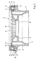
- the suspension strut bearing 6 is formed, among other things, from two support parts, a guide ring 8 directed towards the bearing 4 and an axially spaced apart therefrom Housing 9, between which a roller bearing 10 is arranged.
- first bearing ring 11 is inserted in an annular groove 12 of the guide ring 8.
- the Housing 9 has a circumferential groove 13 into which the second bearing ring 14 is inserted is.
- the housing 9 forms a support surface 15 for a helical spring 16.
- the radial to a longitudinal axis 40 of the strut 1 aligned support surface 15 merges into an axial by means of a radius running guide approach 17.
- the radius is the radius of the spring wire diameter adjusted the coil spring 16.
- the coil spring 16 is provided with a conical end section, the end turns rest on the outer diameter of the guide projection 17.
- the Arrangement of the support surface 15 on the housing 9 is designed so that almost a rectilinear application of force in the strut bearing 6, whereby misalignment is largely avoided.
- the support parts of the strut bearing 6, the guide ring 8 and the housing 9 are made of plastic and thus have compared to conventional designed strut bearings a weight advantage.
- the housing 9 is there provided with hollow chambers 18, whereby a different shrinkage behavior, caused by differences in wall thickness, is avoided and so that a high dimensional accuracy can be achieved.
- the hollow chambers 18 are designed geometrically different and by partition walls 19th separated from each other.
- Forms radially inward from the guide projection 17 the housing 9 has an annular shoulder 21 on which there is a damping element 22 supports, to achieve an elastic end stop for the shock absorber 1, for example when the vehicle is strongly compressed.
- the design the housing 9 sees an almost identical axial spacing the annular shoulder 21 and the support surface 15 to the roller bearing 10 in comparison Compared to previously known struts, this creates a compact housing 9 and a reduced-length damping element 22
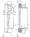
- FIG. 2 shows in a single part drawing that in the figure in the installed state Shock absorber bearing shown 6 Further details of the shock absorber bearing 6 illustrates the enlarged illustration of the suspension strut bearing 6 according to FIG. 2.
- the guide ring 8 forms a largely inverted U-shaped cross-sectional profile.
- a radially inner rim 23 engages in a recess in the installed position 24 of the housing 9.
- a radially outer rim 25 has a longitudinal extension, which extends over the installation height of the rolling bearing 10. ends the rim 25 is provided with a radially inward projection 26, the in a radial groove 27 of the housing 9 to form a snap connection 28 engages.
- the axial length of the protrusion 26 enables formation a labyrinth seal 29 between the projection 26 and the outer contour of the housing 9.
- the labyrinth seal 29 effectively prevents entry of impurities in the suspension strut bearing 6.
- the enlarged image of the suspension strut bearing 6 according to FIG. 2 further clarifies the radial shape Arrangement of the partition walls 19 with which the hollow chambers 18 laterally are limited.
- the trapezoidal shape of the Hollow chambers 18, which are arranged symmetrically circumferentially and by a central cylindrical recess 30 starting from a central Center of the housing 9 are aligned pointing.
- Figure 3 shows a strut bearing 36, the support parts, the guide ring 38 and the housing 39 are joined together by means of a snap connection 33 are.
- the housing 39 has a radially oriented, rotating Nose 35 provided by one end of the board 25 of the guide ring 38 arranged, radially inward projection engages behind positively.
- the housing 39 is further different from the housing 9 according to FIG. 2 is provided with differently designed hollow chambers 31a, 31b, 31c, 32, the due to a larger central recess in diameter 37 in the housing 39 have a different shape.
- the hollow chambers For this purpose, 31a to 31c are concentric about the longitudinal axis 40 of the suspension strut bearing 36 arranged and each by a circumferentially arranged partition 41a, 41b separately.
- the hollow chamber 31a connects axially Towards the hollow chamber 32, between which a partition 20 is provided is.
- FIGS. 4 and 5 Another alternatively designed suspension strut bearing 46 is shown in FIGS. 4 and 5.
- the housing 49 is with a starting from a stop 42, axially continuously increasing support surface 45 on which the Coil spring 16 is supported.
- the stop 42 forms in the installed state a rotary fixation for the coil spring 16.
- the angle " ⁇ " at which the Support surface 45 extends axially rising, is adapted to the design or the course of the end turn of the coil spring 16.
- the of the Stop 42 outgoing, helically axially lifting from the roller bearing 10 Support surface 45 is here by spaced webs 43 connected to the ring portion 44 of the housing 49.
- the guide ring 48 and the housing 49 are connected by a snap connection 33 for Formation of a preassembled, containing all individual parts of the strut bearing 46 Unit.
Landscapes
- Engineering & Computer Science (AREA)
- Mechanical Engineering (AREA)
- Vehicle Body Suspensions (AREA)
- Fluid-Damping Devices (AREA)
Description
Die Radaufhängung bzw. Radführung der gelenkten Vorderräder von Personenkraftfahrzeugen sind versehen mit jeweils einem Federbein. Der Aufbau des Federbeins umfasst einen teleskopartigen Stoßdämpfer und einer diesen umgebenden, als Radfeder dienenden Schraubenfeder, wobei die elastisch an der Fahrzeukarosserie abgestützten Bauteile, der Stoßdämpfer und die Schraubenfeder, in einem Federbeinlager gemeinsam gegenüber der Karosserie, um ihre Längsachse drehbar gelagert sind. Bei einer Lenkbewegung der Räder ermöglicht das Federbeinlager eine Verdrehung zwischen dem Stoßdämpfer und dem mit ihr verbundenen Federteller einerseits und der Karosserie andererseits Das weitere Ende der Schraubenfeder ist drehstarr an dem Stoßdämpfer befestigt. Zur Erzielung eines geringen Verdrehwiderstandes, im Interesse eines geringen zusätzlichen Lenkaufwandes sowie zur Vermeidung einer ungewollten Federtorsion und daraus resultierender Rückstellmomente, ist in dem Federbeinlager ein Wälzlager eingesetztThe wheel suspension or wheel guidance of the steered front wheels of passenger vehicles are each provided with a shock absorber. The structure the strut includes a telescopic shock absorber and one of these surrounding, serving as a wheel spring coil spring, the elastic on the vehicle body supported components, the shock absorber and the Coil spring, in a suspension strut bearing together opposite the body, are rotatably mounted about their longitudinal axis. With a steering movement of the The shock absorber bearing allows wheels to rotate between the shock absorbers and the associated spring plate on the one hand and the body the other end of the coil spring is torsionally rigid on the Shock absorber attached. To achieve a low resistance to rotation, in Interest in a small additional steering effort and to avoid an unwanted spring torsion and the resulting restoring moments, a roller bearing is used in the suspension strut bearing
Eine Vorderradführung bzw. Vorderradaufhängung gemäß der zuvor beschriebenen
Art ist aus der DE 29 13 982 A1 bekannt. Auf den oberen Lagerzapfen
der Stoßdämpfer-Kolbenstange dieser bekannten Radaufhängung ist ein Axial-Wälzlager
befestigt, mit dem eine Verdrehbarkeit des Federbeins gegenüber
der Karosserie sichergestellt ist. An dem unteren Ring des Axial-Wälzlagers
stützt sich über einen Federteller sowohl die Kolbenstange des Stoßdämpfers
als auch gleichzeitig die zugeordnete Schraubenfeder ab Die von dem Stoßdampfer
und der Schraubenfeder gemeinsam auf das Walzlager ausgeübten
Kräfte werden von dem Wälzlager über ein elastisches Stützlager auf die Karosserie
übertragen.A front wheel guide or front suspension according to the previously described
Art is known from
Die aus der gattungsbildenden DE 197 52 269 A1 bekannte Federbeinlagerung schließt zwei Trägerteile ein, zwischen denen ein Wälzlager angeordnet ist. In einem ersten drehfest mit der Karosserie verbunden Trägerteil ist ein Lagerring des Wälzlagers eingesetzt. Das rotationssymmetrisch gestaltete, kreisringförmige Trägerteil besitzt außenseitig eine axial vorstehende Wandung, die sich über die gesamte Einbauhöhe des Wälzlagers erstreckt. Am freien Ende hintergreift die Wandung des drehstarren Trägerteils einen radial nach außen gerichteten Bord des zweiten Trägerteils, in das der zweite Lagerring eingesetzt ist. Außenseitig, auf der vom Wälzlager abgewandten Seite des aus Stahlblech geformten Trägerteils stützt sich die Schraubenfeder des Federbeins ab. Das Federbein ist weiterhin mit einem Dämpfungselement zur Erzielung eines elastischen Endanschlages bei einer starken Einfederung versehen, das sich unmittelbar an der Karosserie abstützt.The strut mounting known from the generic DE 197 52 269 A1 closes two support parts a, between which a roller bearing is arranged. In a first the bearing part is a bearing ring of the rolling bearing used. The rotationally symmetrical, circular support part has an axially protruding wall on the outside, which extends over the entire Installation height of the rolling bearing extends. At the free end it reaches behind Wall of the torsionally rigid support part a radially outward Board of the second carrier part, in which the second bearing ring is inserted. On the outside, on the side facing away from the rolling bearing and made of sheet steel Carrier part supports the coil spring of the shock absorber. The Suspension strut is also provided with a damping element to achieve an elastic Provide end stop with a strong deflection, which is immediate supported on the body.
Ausgehend von dem bekannten Stand der Technik liegt der Erfindung die Aufgabe zu Grunde, ein gewichtsoptimiertes, kompaktes Federbeinlager zu schaffen, mit einer verbesserten Steifigkeit sowie reduzierten Herstellkosten.Starting from the known prior art, the object of the invention based on a weight-optimized, compact suspension strut bearing create, with an improved rigidity and reduced manufacturing costs.
Die zuvor genannte Problemstellung wird durch die Merkmale der Erfindung
gemaß Anspruch 1 gelöst. Das erfindungsgemäße Federbein für eine Radaufhängung
von Fahrzeugen schließt ein Federbeinlager ein, das zwei Trägerteile
umfasst, zwischen denen ein Wälzlager angeordnet ist. Vorteilhaft sind beide
Trägerteile aus Kunststoff hergestellt, wodurch sich insbesondere ein Gewichtsvorteil
gegenüber bislang aus Blech hergestellten Trägerteilen bzw. aus
unterschiedlichen Werkstoffen hergestellten Tragerteilen einstellt. Für die Herstellung
der Trägerteile, die als Führungsring bzw. als Gehäuse ausgebildet
sind, eignet sich bevorzugt ein Spritzgießverfahren, mit dem sich für Großserien
ein Kostenvorteil einstellt. Die erfindungsgemäßen Trägerteile sind so konzipiert,
dass diese ohne nachteiligen Einfluss auf die Festigkeit ein Optimum
hinsichtlich des Gewichts und des Bauraums darstellen. Erfindungsgemäß ist
das der Schraubenfeder des Federbeins zugeordnete, als Gehäuse bezeichnete
Trägerteil mit Hohlkammern versehen, wodurch sich ein Gewichtsvorteil
einstellt. Die Hohlkammern des Trägerteils ermöglichen darüber hinaus in allen
Bereichen gleiche Wandstärken, was sich insbesondere auf die Festigkeit
auswirkt. Die gleichen Querschnitte vermeiden außerdem ein nachteiliges unterschiedliches
Schrumpfungsverhalten und damit die Einhaltung vorgegebener
enger Form- und / oder Lagetoleranzen. Als ein geeigneter Kunststoff für
die Trägerteile eignet sich bevorzugt PA 66 GF oder PA 66 GB. Auf der zur
Schraubenfeder gerichteten Seite ist das als Gehäuse bezeichnete Trägerteil
mit einem Führungsansatz sowie einer Abstützfläche für die Schraubenfeder
versehen. Die Abstützfläche ist dabei so angeordnet, dass sich eine nahezu
geradlinige Krafteinleitung in das Federbeinlager einstelltThe aforementioned problem is solved by the features of the invention
solved according to
Zur Erzielung einer exakten Einbaulage des Wälzlagers ist dieses in beiden Trägerteilen in einer Ringnut bzw. einer Umlaufnut eingesetzt. Sowohl die Ringnut des Führungsrings als auch die Umlaufnut des Gehäuses ist beidseitig von Borden seitlich begrenzt. In der Einbaulage ist das Wälzlager an zumindest einem Bord der Ringnut oder der Umlaufnut zentriert. Eine bevorzugte Einbaulage sieht vor, dass das Wälzlager an einem Bord des Führungsrings und einem Bord des Gehäuses gleichzeitig zentriert ist. Ein weiteres Gestaltungsmerkmal der Erfindung sieht vor, den inneren Bord der Umlaufnut des Gehäuses mit einer Ausnehmung zu versehen, in die der radial innere Bord des Führungsrings im eingebauten Zustand eingreift. Dieser vorteilhafte formschlüssige, spielbehaftete Eingriff beider Borde bewirkt eine labyrinthartige innenseitige Abdichtung des Federbeinlagers, die sich vorteilhaft auf die Lebensdauer auswirktTo achieve an exact installation position of the rolling bearing, this is in both Carrier parts used in an annular groove or a circumferential groove. Both the The ring groove of the guide ring and the circumferential groove of the housing are on both sides laterally limited by borders. In the installed position, the rolling bearing is at least on centered on a board of the ring groove or the circumferential groove. A preferred one Installation position provides that the rolling bearing on a board of the guide ring and a board of the housing is centered at the same time. Another design feature the invention provides the inner board of the circulation groove of the To provide the housing with a recess into which the radially inner rim of the guide ring engages when installed. This advantageous form-fitting, playful engagement of both shelves creates a labyrinthine internal sealing of the shock absorber bearing, which is advantageous for the service life effect
Weitere vorteilhafte Ausgestaltungen der Erfindung sind Gegenstand der Ansprüche
2 bis 19 Further advantageous embodiments of the invention are the subject of the
Zur Erzielung einer ausreichenden Führung der Schraubenfeder ist das Gehäuse des Federbeinlagers mit einem Führungsansatz versehen, dessen Länge zumindest die Längserstreckung einer Federwindung übertrifft. Der Endbereich der Schraubenfeder ist dabei mit einem abnehmenden Windungsdurchmesser versehen, wodurch die Schraubenfeder innenseitig an dem Führungsansatz eine Längsführung erhält und gleichzeitig zentriert ist.The housing is used to achieve adequate guidance of the coil spring the shock absorber bearing with a guide extension, its length at least exceeds the longitudinal extent of a spring turn. The end area the coil spring is with a decreasing winding diameter provided, whereby the coil spring on the inside of the guide projection receives a longitudinal guide and is centered at the same time.
In einer weiteren vorteilhaften Ausgestaltung der Erfindung ist das Gehäuse, d. h. der Schraubenfeder zugeordnete Trägerteil, mit einer Ringschulter versehen, die von dem Führungsansatz ausgehend radial nach innen ausgerichtet ist. An der Ringschulter stützt sich ein Dämpfungselement ab, das bei einer starken Einfederung des Fahrzeugs einen elastischen Endanschlag für das Federbein bildet. Vorzugsweise ist die Ringschulter kreisringförmig gestaltet und rechtwinklig zu der Längsachse des Federbeinlagers ausgerichtet. Die Ausbildung der Ringschulter in Verbindung mit dem Führungsansatz eignet sich für eine Lagepositionierung des Dämpfungselementes, das formschlüssig an der Innenwandung des Führungsansatzes gehalten bzw. zentriert ist. Alternativ dazu kann das Dämpfungselement ebenfalls spielbehaftet angeordnet sein, so dass sich ein Ringspalt zwischen der Mantelfläche des Dämpfungselementes und der Innenwandung des Führungsansatzes bildet.In a further advantageous embodiment of the invention, the housing is d. H. support part assigned to the coil spring, provided with an annular shoulder, the radially inward starting from the guide approach is. At the ring shoulder, a damping element is supported, which at one strong deflection of the vehicle an elastic end stop for that Strut forms. The annular shoulder is preferably designed in the shape of a circular ring and aligned perpendicular to the longitudinal axis of the strut mount. The Training the ring shoulder in connection with the leadership approach is suitable in favor of a positional positioning of the damping element that is form-fitting is held or centered on the inner wall of the guide projection. alternative for this purpose, the damping element can also be arranged with play be so that there is an annular gap between the outer surface of the damping element and forms the inner wall of the guide approach.
Die Abstützung des Dämpfungselementes an der Ringschulter hat zur Folge, dass auch in Extremsituationen, d. h. bei einer starken Einfederung oder extremen Kurvengeschwindigkeiten, bei der es zu einer Blockanlage des Federbeins kommt, die dabei entstehenden Lenkkräfte nicht extrem ansteigen. Aufgrund der Abstutzung des Dämpfungselementes an der Ringschulter des Gehäuses, welches über ein Wälzlager an dem benachbarten Trägerteil abgestützt ist, stellen sich auch bei einer Blockanlage des Federbeins beherrschbare Lenkkräfte ein.The result of supporting the damping element on the ring shoulder is that that even in extreme situations, i.e. H. with a strong deflection or extreme Cornering speeds at which there is a blockage of the shock absorber comes, the resulting steering forces do not increase extremely. by virtue of the support of the damping element on the ring shoulder of the housing, which is supported on the adjacent carrier part via a roller bearing is manageable even with a block system of the shock absorber Steering forces.
Die Abstützfläche des Trägerteils bildet einen Anschlag, mit dem in einfacher Weise eine wirksame Verdrehsicherung für die Schraubenfeder erzielbar ist Die Schraubenfeder stützt sich dabei mit einem Federende an dem Anschlag ab und positioniert damit die Schraubenfeder in der Einbaulage. Von dem Anschlag ausgehend steigt die Abstützfläche auf den Umfang bezogen zumindest über einen Winkel von 90° zunehmend kontinuierlich axial an. Dieser Winkelwert kann sich bei Bedarf auf einen Bereich von mehr als 90° erstrecken. Der Anstiegsverlauf an der Abstützfläche bzw. der Steigungswinkel entspricht dabei der Endwindung der Schraubenfeder. Mit dieser Maßnahme kann beispielsweise eine Fehlmontage von Schraubenfedern verhindert werden, die unterschiedlich ausgebildete Federenden aufweisen.The support surface of the support part forms a stop with which in simple An effective protection against rotation for the coil spring can be achieved The coil spring is supported with a spring end on the stop and positions the coil spring in the installed position. From the attack based on the circumferential support surface increases at least over an angle of 90 ° increasingly axially. This angular value can extend over 90 ° if necessary. The The course of the rise on the support surface or the gradient angle corresponds to this the end turn of the coil spring. With this measure, for example incorrect assembly of coil springs can be prevented, which varies have trained spring ends.
Das der Schraubenfeder zugeordnete Trägerteil bildet außerdem eine Ringschulter, die radial nach innen versetzt zum Führungsansatz angeordnet ist, und an der sich das Dämpfungselement für das Federbein abstützt. Damit übernimmt dieses Trägerteil mehrere Funktionen, was sich insbesondere vorteilhaft auf die Montage der einzelnen Bauteile des Federbeins auswirkt. Aufgrund der Lage der Ringschulter im Gehäuse, die weitestgehend mit der Lage der Abstützfläche für die Schraubenfeder übereinstimmt, kann im Vergleich zu bisherigen Lösungen ein längenreduziertes Dämpfungselement eingesetzt werden, was die kompakte Bauweise der erfindungsgemäßen Federbeinlagerung unterstreicht.The support part assigned to the coil spring also forms an annular shoulder, which is arranged radially inwards to the guide shoulder, and on which the damping element for the shock absorber is supported. In order to this carrier part takes on several functions, which is particularly advantageous affects the assembly of the individual components of the shock absorber. by virtue of the position of the ring shoulder in the housing, which largely corresponds to the position the support surface for the coil spring matches, compared to previous solutions used a length-reduced damping element be what the compact design of the strut mounting according to the invention underlines.
Auf der von der Abstützfläche der Schraubenfeder abgewandten Seite ist das der Schraubenfeder zugeordnete Trägerteil, das Gehäuse, mit einer Umlaufnut versehen, in der ein Wälzlagerring eingepasst ist. Der weitere Lagerring des Wälzlagers ist dem drehfest an der Karosse des Fahrzeugs angeordneten Trägerteils, dem Führungsring zugeordnet. Dazu weist der Führungsring zwei Borde auf, zwischen denen der Wälzlagerring formschlüssig gehalten ist. Beide Borde besitzen eine Längserstreckung, die sich in einer Einbaulage des Führungsrings zumindest bis über die Mitte des Wälzlagers erstrecken.This is on the side facing away from the support surface of the coil spring the coil part associated with the coil spring, the housing, with a circumferential groove provided in which a roller bearing ring is fitted. The further bearing ring of the Rolling bearing is the carrier part arranged in a rotationally fixed manner on the body of the vehicle, assigned to the guide ring. For this purpose, the guide ring has two rims on, between which the rolling bearing ring is held positively. Both Borders have a longitudinal extension, which is in the installed position of the guide ring extend at least to the middle of the rolling bearing.
Der radial innere Bord des Führungsrings greift in dem eingebauten Zustand in eine Ausnehmung ein, die dem als Axiallager ausgelegten Federbeinlager benachbart ist Der radial äußere Bord des Lagerrings ist mit einer Schnappnase versehen, die mit einer Ausnehmung einer äußeren Wandung des Gehauses zur Bildung einer Schnappverbindung zusammenwirkt The radially inner rim of the guide ring engages in the installed state a recess that is adjacent to the strut bearing designed as a thrust bearing is The radially outer rim of the bearing ring is with a snap lug provided with a recess of an outer wall of the housing cooperates to form a snap connection
Durch die formschlüssige Verbindung der Trägerteile mittels einer zwischen dem Gehäuse und dem Führungsring angeordneten Schnappverbindung ist eine vormontierbare Einheit geschaffen, die alle Bauteile der Federbeinlagerung zusammenfügt. Damit ergibt sich die Möglichkeit, den Fahrzeugherstellern die vormontierte Federbeinlagerung als eine Baueinheit zu liefern, um den Bauteileumfang deutlich reduzieren zu können.Due to the positive connection of the carrier parts by means of a between the housing and the guide ring arranged snap connection a preassembled unit created that all components of the strut mounting assembles. This gives the opportunity to vehicle manufacturers to deliver the preassembled strut mounting as one unit to the To be able to significantly reduce the scope of components.
Die zwischen dem Gehäuse und dem Führungsring angeordnete Schnappverbindung kann erfindungsgemäß zusätzlich als eine Labyrinthdichtung ausgelegt werden. Das Federbeinlager ist damit vor einem Eintritt von Verunreinigungen jeglicher Art geschützt, was sich vorteilhaft auf die Lebensdauer, die Standzeit der Lagerung auswirkt.The snap connection arranged between the housing and the guide ring can also be designed according to the invention as a labyrinth seal become. The suspension strut bearing is thus protected from contamination protected of any kind, which is beneficial to the life span Storage life affects.
Das der Schraubenfeder zugeordnete Trägerteil, das Gehäuse ist gemäß der Erfindung mit umfangsverteilt angeordneten Hohlräumen versehen. Die Gestaltung der Hohlräume erfolgt unter dem Gesichtspunkt, möglichst gleiche Querschnitte im Gehäuse zu erzielen. Damit stellt sich ein gleiches Schrumpfungsverhalten des aus Kunststoff hergestellten Gehäuses ein, was sich vorteilhaft auf Form- und Lagetoleranz und allgemein auf die Formgenauigkeit bzw. Fertigungstoleranz des gesamten Gehäuses auswirkt. Die Hohlräume bzw. Hohlkammern bewirken weiterhin einen Gewichtsvorteil ohne nachteiligen Einfluss auf die Festigkeit. Vorzugsweise ist das Gehäuse mit symmetrisch angeordneten Hohlräumen versehen, die jeweils von strahlenförmig auf eine Mitte des Federbeinlagers ausgerichteten Zwischenwänden getrennt sind. Dabei bilden sich jeweils Hohlräume mit einer trapezförmig gestalteten Grundflache. Weiterhin kann jeder Hohlraum mit einer Zwischenwand versehen werden, die eine Aufteilung der Hohlräume in axialer Richtung sicherstellt. Der Gehauseaufbau schließt weiterhin radial zueinander beabstandet angeordnete Hohlkammern ein. Eine weitere Ausbildung sieht vor, dass sich die Hohlräume bis in den Führungsansatz erstrecken, auf dem ein Ende der Schraubenfeder außenseitig anliegt Diese Maßnahme gewährleistet auch in dem konisch zulaufenden Abschnitt des Führungsansatzes eine gleiche Wandstärke zur Erzielung eines einheitlichen Schrumpfungsyerhaltens. The associated with the coil spring support part, the housing is according to the Invention provided with circumferentially distributed cavities. The design the cavities are made from the point of view, if possible the same To achieve cross sections in the housing. This results in the same shrinkage behavior of the housing made of plastic, which is advantageous on shape and position tolerance and generally on shape accuracy or manufacturing tolerance of the entire housing. The cavities or hollow chambers also bring about a weight advantage without disadvantage Influence on strength. The housing is preferably symmetrical arranged cavities provided, each radiating from one Center partitions aligned partition walls are separated. Cavities are formed with a trapezoidal base. Furthermore, each cavity can be provided with an intermediate wall, which ensures a division of the cavities in the axial direction. The Housing construction also closes radially spaced apart Hollow chambers. Another training provides that the cavities extend into the guide boss on which one end of the coil spring on the outside This measure also guarantees in the tapered Section of the guide approach an equal wall thickness to achieve uniform shrinkage retention.
Zur Erläuterung der Erfindung dienen einige Ausführungsbeispiele, die nachfolgend erläutert werden. Es zeigen:
Figur 1- ein erfindungsgemäßes Federbein in einem Längsschnitt;
Figur 2- die
Federbeinlagerung gemäß Figur 1 in einer Einzelteilzeichnung; Figur 3- eine zu Figur 2 alternativ gestaltete Federbeinlagerung,
- Figur 4
- in einer Ansicht eine Federbeinlagerung, versehen mit einer kontinuierlich ansteigenden Abstützfläche für die Schraubenfeder;
Figur 5- in einem Längsschnitt das Federbeinlager gemäß Figur 4.
- Figure 1
- a strut according to the invention in a longitudinal section;
- Figure 2
- the suspension strut mounting according to Figure 1 in a single part drawing;
- Figure 3
- a strut mounting designed as an alternative to FIG. 2,
- Figure 4
- in a view a suspension strut bearing, provided with a continuously increasing support surface for the coil spring;
- Figure 5
- in a longitudinal section the suspension strut bearing according to FIG. 4.
In Figur 1 ist ein Federbein 1 abgebildet, versehen mit einem Stoßdämpfer 2,
dessen Kolbenstange 3 über ein elastisches Lager 4 an einer Fahrzeugkarosserie
5 abgestützt ist. Auf der von der Fahrzeugkarosserie 5 abgewandten
Seite schließt sich an das Lager 4 ein Federbeinlager 6 an. Das Lager 4 bildet
dazu eine Aufnahme 7, in die das Federbeinlager 6 formschlüssig eingepasst
ist. Das Federbeinlager 6 wird gebildet unter anderem aus zwei Tragerteilen,
einem zum Lager 4 gerichteten Führungsring 8 und einem axial dazu beabstandeten
Gehäuse 9, zwischen denen ein Wälzlager 10 angeordnet ist. Ein
erster Lagerring 11 ist in einer Ringnut 12 des Führungsrings 8 eingesetzt. Das
Gehäuse 9 weist eine Umlaufnut 13 auf, in die der zweite Lagerring 14 eingefügt
ist.1 shows a
Axial versetzt zur Umlaufnut 13 bildet das Gehäuse 9 eine Abstützfläche 15 für
eine Schraubfeder 16. Die radial zu einer Längsachse 40 des Federbeins 1
ausgerichtete Abstützfläche 15 geht mittels eines Radius über in einen axial
verlaufenden Führungsansatz 17. Der Radius ist dabei dem Radius des Federdrahtdurchmessers
der Schraubenfeder 16 angepasst. Die Schraubenfeder 16
ist versehen mit einem konisch verlaufenden Endabschnitt, dessen Endwindungen
an dem Außendurchmesser des Führungsansatzes 17 anliegen. Die
Anordnung der Abstützfläche 15 an dem Gehäuse 9 ist so angelegt, dass sich
nahezu eine geradlinige Krafteinleitung in das Federbeinlager 6 einstellt, wodurch
eine Schiefstellung weitestgehend vermieden wird.Axially offset from the
Die Tragerteile des Federbeinlagers 6, der Führungsring 8 sowie das Gehäuse
9 sind aus Kunststoff hergestellt und besitzen damit gegenüber herkömmlich
gestalteten Federbeinlagern einen Gewichtsvorteil. Das Gehäuse 9 ist dabei
mit Hohlkammern 18 versehen, wodurch ein unterschiedliches Schrumpfungsverhalten,
hervorgerufen durch Wandstärkenunterschiede, vermieden wird und
damit eine hohe Formgenauigkeit erreicht werden kann. Die Hohlkammern 18
sind dabei geometrisch abweichend gestaltet und durch Zwischenwände 19
voneinander getrennt. Vom Führungsansatz 17 radial nach innen zeigend bildet
das Gehäuse 9 eine Ringschulter 21, an der sich ein Dämpfungselement
22 abstützt, zur Erzielung eines elastischen Endanschlages für das Federbein
1, beispielsweise bei einem starken Einfedern des Fahrzeugs. Die Gestaltung
des Gehauses 9 sieht eine nahezu übereinstimmende axiale Beabstandung
der Ringschulter 21 und der Abstützflache 15 zum Wälzlager 10 vor Im Vergleich
zu bisher bekannten Federbeinen stellt sich dadurch ein kompaktes Gehause
9 ein sowie ein längenreduziertes Dämpfungselement 22The support parts of the
Die Figur 2 zeigt in einer Einzelteilzeichnung das in Figur im eingebauten Zustand
abgebildete Federbeinlager 6 Weitere Einzelheiten des Federbeinlagers
6 verdeutlicht die vergrößerte Abbildung des Federbeinlagers 6 gemäß Figur 2.
Der Führungsring 8 bildet ein weitestgehend umgekehrt u-förmiges Querschnittsprofil.
Ein radial innerer Bord 23 greift in der Einbaulage in eine Ausnehmung
24 des Gehäuses 9. Ein radial äußerer Bord 25 besitzt eine Längserstreckung,
die sich über die Einbauhöhe des Wälzlagers 10 erstreckt. Endseitig
ist der Bord 25 mit einem radial nach innen gerichteten Vorsprung 26 versehen,
der in eine Radialnut 27 des Gehäuses 9 zur Bildung einer Schnappverbindung
28 eingreift. Die axiale Länge des Vorsprungs 26 ermöglicht die Bildung
einer Labyrinthdichtung 29 zwischen dem Vorsprung 26 und der Außenkontur
des Gehäuses 9. Die Labyrinthdichtung 29 verhindert wirksam den Eintrag
von Verunreinigungen in das Federbeinlager 6. Die vergrößerte Abbildung
des Federbeinlagers 6 gemäß Figur 2 verdeutlicht weiterhin die strahlenförmige
Anordnung der Zwischenwände 19, mit denen die Hohlkammern 18 seitlich
begrenzt sind. Erkennbar ist weiterhin die trapezförmige Formgebung der
Hohlkammern 18, die symmetrisch umfangsverteilt angeordnet sind und von
einer zentrischen zylindrischen Ausnehmung 30 ausgehend, auf eine zentrische
Mitte des Gehäuses 9 zeigend ausgerichtet sind.Figure 2 shows in a single part drawing that in the figure in the installed state
Shock absorber bearing shown 6 Further details of the
Die Figur 3 zeigt ein Federbeinlager 36, dessen Trägerteile, der Führungsring
38 sowie das Gehäuse 39 mittels einer Schnappverbindung 33 zusammengefügt
sind. Dazu ist das Gehäuse 39 mit einer radial ausgerichteten, umlaufenden
Nase 35 versehen, die von einem endseitig am Bord 25 des Führungsrings
38 angeordneten, radial nach innen gerichteten Vorsprung formschlüssig hintergreift.
Das Gehäuse 39 ist weiterhin im Unterschied zu dem Gehäuse 9 gemäß
Figur 2 mit abweichend gestalteten Hohlkammern 31a, 31b, 31c, 32 versehen,
die aufgrund einer im Durchmesser größeren zentrischen Ausnehmung
37 im Gehäuse 39 eine abweichende Formgebung aufweisen. Die Hohlkammern
31a bis 31c sind dazu konzentrisch um die Längsachse 40 des Federbeinlagers
36 angeordnet und jeweils durch eine umlaufend angeordnete Zwischenwand
41a, 41b getrennt. An die Hohlkammer 31a schließt sich in axialer
Richtung die Hohlkammer 32 an, zwischen denen eine Trennwand 20 vorgesehen
ist. Figure 3 shows a strut bearing 36, the support parts, the
Ein weiteres alternativ gestaltetes Federbeinlager 46 zeigen die Figuren 4 und
5. Das Gehäuse 49 ist dabei mit einer von einem Anschlag 42 ausgehenden,
axial kontinuierlich ansteigenden Abstützfläche 45 versehen, an der sich die
Schraubenfeder 16 abstützt. Der Anschlag 42 bildet im eingebauten Zustand
eine Drehfixierung für die Schraubenfeder 16. Der Winkel "α", unter dem die
Abstützfläche 45 axial ansteigend verläuft, ist dabei angepasst an die Gestaltung
bzw. dem Verlauf der Endwindung von der Schraubfeder 16. Die von dem
Anschlag 42 ausgehende, schraubenlinienförmig axial vom Wälzlager 10 abhebende
Abstützfläche 45 ist dabei durch beabstandet angeordnete Stege 43
mit dem Ringabschnitt 44 des Gehäuses 49 verbunden. Der Führungsring 48
und das Gehäuse 49 sind durch eine Schnappverbindung 33 verbunden, zur
Bildung einer vormontierbaren, alle Einzelteile des Federbeinlagers 46 beinhaltenden
Einheit. Another alternatively designed suspension strut bearing 46 is shown in FIGS. 4 and
5. The
- 11
- Federbeinstrut
- 22
- Stoßdämpfershock absorber
- 33
- Kolbenstangepiston rod
- 44
- Lagercamp
- 55
- Fahrzeugkarosserievehicle body
- 66
- FederbeinlagerStrut mounts
- 77
- Aufnahmeadmission
- 88th
- Führungsringguide ring
- 99
- Gehäusecasing
- 1010
- Wälzlagerroller bearing
- 1111
- Lagerringbearing ring
- 1212
- Ringnutring groove
- 1313
- Umlaufnutcircumferential groove
- 1414
- Lagerringbearing ring
- 1515
- Abstützflächesupporting
- 1616
- Schraubenfedercoil spring
- 1717
- Führungsansatzleadership approach
- 1818
- Hohlkammerhollow
- 1919
- Zwischenwandpartition
- 2020
- Trennwandpartition wall
- 2121
- Ringschulterannular shoulder
- 2222
- Dämpfungselementdamping element
- 2323
- Bordshelf
- 2424
- Ausnehmungrecess
- 2525
- Bordshelf
- 2626
- Vorsprunghead Start
- 2727
- Radialnutradial groove
- 2828
- Schnappverbindungsnap
- 2929
- Labyrinthdichtunglabyrinth seal
- 3030
- Ausnehmungrecess
- 31a31a
- Hohlkammerhollow
- 31b31b
- Hohlkammerhollow
- 31c31c
- Hohlkammerhollow
- 3232
- Hohlkammerhollow
- 3333
- Schnappverbindungsnap
- 3434
- Vorsprunghead Start
- 3535
- Nasenose
- 3636
- FederbeinlagerStrut mounts
- 3737
- Ausnehmungrecess
- 3838
- Führungsringguide ring
- 3939
- Gehäusecasing
- 4040
- Längsachselongitudinal axis
- 4141
- Zwischenwandpartition
- 4242
- Anschlagattack
- 4343
- Stegweb
- 4444
- Ringabschnittring section
- 4545
- Abstützflächesupporting
- 4646
- FederbeinlagerStrut mounts
- 4747
- Führungsansatzleadership approach
- 4848
- Führungsringguide ring
- 4949
- Gehäusecasing
Claims (19)
- Suspension strut for a wheel suspension in vehicles, comprising a shock absorber (2) and a helical spring (16) which surrounds the shock absorber (2) at least partially coaxially and which is supported with one spring end on a spring support of the shock absorber (2) and with the further spring end indirectly on a suspension strut bearing (6, 36, 46), the suspension strut bearing (6, 36, 46) comprising two carrier parts, between which a rolling bearing (10) is arranged, a first carrier part designed as a guide ring (8, 38, 48) and assigned to a vehicle body (5) and, as the second carrier part, a one-part housing (9, 39, 49) which has hollow chambers (18, 31a to 31c, 32) and which surrounds the shock absorber (2) partially concentrically and which has a guide extension (17, 47) and a supporting surface (15, 45) for the helical spring (16), characterized in that the carrier parts, the guide ring (8, 38, 48) and the housing (9, 39, 49) are produced from plastic, for the reception of the rolling bearing (10) the guide ring (8, 38, 48) having an annular groove (12) delimited laterally on both sides by rims (23, 25) and the housing (9, 39, 49) having a peripheral groove (13) delimited on both sides by rims, the rolling bearing (10) being centred at at least one rim, and a radially inner rim of the guide ring (8, 48) engaging into a recess (24) of the inner rim of the peripheral groove (13) of the housing (9).
- Suspension strut according to Claim 1, an end region of the helical spring (16), with a decreasing turn diameter, surrounding the guide extension (17, 47) of the housing (9, 39, 49) on the outside.
- Suspension strut according to Claim 2, the guide extension (17) of which has a longitudinal extent which exceeds at least one spring turn of the helical spring (16).
- Suspension strut according to Claim 1, in which the housing (9) is provided with an annular shoulder (21) which, emanating from the guide extension (17), is oriented peripherally inwards.
- Suspension strut according to Claim 4, in which the annular shoulder (21) is configured in the form of a circular ring and runs at right angles to a longitudinal axis (40) of the suspension strut bearing (6).
- Suspension strut according to Claim 4, the annular shoulder (21) of which is provided for supporting a damping element (22) which is held positively on an inner wall of the guide extension (17) or is inserted with play in the guide extension (17).
- Suspension strut according to Claim 4, the position of the annular shoulder (21) in the housing (9) coinciding as far as possible with an axial position of the supporting surface (15) for the helical spring (16).
- Suspension strut according to Claim 1, the housing (49) of which has a supporting surface (45) with a stop (42) at which a spring end of the helical spring (16) is fixed rotationally in an installation position.
- Suspension strut according to Claim 8, the supporting surface (45) of which, emanating from the stop (42), rises axially continuously through an angle (α) over at least 90° with respect to a circumference.
- Suspension strut according to Claim 9, a rise of the supporting surface (45) coinciding with a turn direction of the helical spring (16).
- Suspension strut according to Claim 1, the peripheral groove (13) intended for receiving a bearing ring (14) of the suspension strut bearing (6, 36, 46) being introduced on that side of the housing (9, 39, 49) which faces away from the supporting surface (15, 45) for the helical spring (16).
- Suspension strut according to Claim 1, in which the radially outer rim (25) has a radially inward-directed projection (26) which engages into a radial groove (27) of an outer wall of the housing (9) in order to form a snap connection (28).
- Suspension strut according to Claim 1, in which all the components of the suspension strut bearing (6) are combined as a preassemblable unit by means of the snap connection (28) arranged between the housing (9) and the guide ring (8).
- Suspension strut according to Claim 13, the snap connection (28) provided between the housing (9) and the guide ring (8) assuming at the same time the function of a labyrinth seal (29).
- Suspension strut according to Claim 1, the housing (9, 39, 49) of which is provided with symmetrically arranged hollow chambers (18, 31a to 31c, 32).
- Suspension strut according to Claim 15, in which the hollow chambers (31a to 31c) of the housing (39) are arranged so as to be spaced apart radially.
- Suspension strut according to Claim 15, the hollow chambers (18) being separated by intermediate walls (19) oriented in a radiating manner, in order to form hollow chambers (18) of trapezoidal configuration.
- Suspension strut according to Claim 15, the housing (39) having partitions (20) which ensure an axial division of the hollow chambers (31a and 32).
- Suspension strut according to Claim 15, the hollow chambers (18) of which extend axially into the guide extension (17).
Applications Claiming Priority (3)
| Application Number | Priority Date | Filing Date | Title |
|---|---|---|---|
| DE19960699A DE19960699B4 (en) | 1999-12-16 | 1999-12-16 | Strut bearing |
| DE19960699 | 1999-12-16 | ||
| PCT/EP2000/011327 WO2001044003A1 (en) | 1999-12-16 | 2000-11-16 | Suspension strut bearing |
Publications (2)
| Publication Number | Publication Date |
|---|---|
| EP1237741A1 EP1237741A1 (en) | 2002-09-11 |
| EP1237741B1 true EP1237741B1 (en) | 2004-08-04 |
Family
ID=7932887
Family Applications (1)
| Application Number | Title | Priority Date | Filing Date |
|---|---|---|---|
| EP00976029A Expired - Lifetime EP1237741B1 (en) | 1999-12-16 | 2000-11-16 | Suspension strut bearing |
Country Status (4)
| Country | Link |
|---|---|
| US (1) | US6948728B2 (en) |
| EP (1) | EP1237741B1 (en) |
| DE (2) | DE19960699B4 (en) |
| WO (1) | WO2001044003A1 (en) |
Families Citing this family (50)
| Publication number | Priority date | Publication date | Assignee | Title |
|---|---|---|---|---|
| FR2829429B1 (en) * | 2001-09-12 | 2003-12-12 | Skf Ab | STOP SUSPENSION DEVICE |
| FR2835297B1 (en) * | 2002-01-29 | 2004-04-16 | Skf Ab | FIXING SUPPORT, ROLLING BEARING AND ASSEMBLY METHOD THEREFOR |
| FR2841990B1 (en) * | 2002-07-02 | 2005-07-29 | Skf Ab | INSTRUMENTAL BEARING BEARING DEVICE AND ELECTRIC MOTOR THUS EQUIPPED |
| FR2851624B1 (en) * | 2003-02-26 | 2006-03-31 | Skf Ab | INSTRUMENT BEARING BEARING |
| JP3944907B2 (en) * | 2003-03-14 | 2007-07-18 | マツダ株式会社 | Front suspension device for automobile |
| JP4378983B2 (en) * | 2003-03-25 | 2009-12-09 | オイレス工業株式会社 | Strut plain bearing |
| FR2853065B1 (en) * | 2003-03-27 | 2006-01-06 | Skf Ab | PORTABLE MEASURING INSTRUMENT, PARTICULARLY FOR SPORT PRACTICE. |
| FR2856447B1 (en) | 2003-06-18 | 2005-09-09 | Skf Ab | CLUTCH FASTENING AND MOUNTING METHOD |
| FR2856757B1 (en) * | 2003-06-27 | 2006-10-20 | Skf Ab | INSTRUMENT BEARING BEARING AND ENCODER FOR INFORMATION SENSOR ASSEMBLY |
| FR2858376B1 (en) * | 2003-07-28 | 2006-03-03 | Skf France | FREEWHEEL BEARING DEVICE WITH TORQUE LIMITER. |
| FR2859412B1 (en) * | 2003-09-04 | 2006-02-24 | Skf Ab | STOP SUSPENSION DEVICE |
| FR2861459B1 (en) * | 2003-10-22 | 2006-02-24 | Skf Ab | ABSOLUTE MULTITOUR HIGH RESOLUTION ROTATION MEASUREMENT SYSTEM AND BEARING EQUIPPED WITH SUCH A SYSTEM. |
| DE102004021497A1 (en) | 2004-04-30 | 2005-12-01 | Zf Friedrichshafen Ag | Suspension strut |
| FR2871231B1 (en) * | 2004-06-02 | 2006-09-15 | Skf Ab | METHOD FOR CONTROLLING THE TENSIONING OF A ROD, OF THE TYPE OF SCREW OR ASSEMBLY PIN, AND DEVICE FOR IMPLEMENTING SUCH A METHOD |
| FR2872558B1 (en) * | 2004-07-02 | 2006-09-29 | Skf Ab | CLUTCH FASTER AND METHOD OF MANUFACTURE |
| DE102005039736A1 (en) * | 2005-08-23 | 2007-03-01 | Schaeffler Kg | Strut mounts |
| JP4636009B2 (en) * | 2006-02-21 | 2011-02-23 | 東海ゴム工業株式会社 | Spring seat for vehicle suspension |
| DE102006027806A1 (en) * | 2006-06-16 | 2007-12-20 | Schaeffler Kg | Spring strut bearing for use in motor vehicle, has sealing unit with sealing ring, which is movably provided between lower and upper parts of bearing housing and seals joint at inner circumference and/or at outer circumference of housing |
| FR2902699B1 (en) | 2006-06-26 | 2010-10-22 | Skf Ab | SUSPENSION STOP DEVICE AND FORCE LEG. |
| DE102006031943A1 (en) * | 2006-07-11 | 2008-01-17 | Schaeffler Kg | thrust roller bearing |
| FR2904261B1 (en) * | 2006-07-26 | 2011-05-13 | Roulements Soc Nouvelle | STOPPER OF SUSPENSION AND SUSPENSION LEG WITH SUCH A ROCKET |
| US8070144B2 (en) * | 2006-08-31 | 2011-12-06 | Honda Motor Co., Ltd. | Assembly guide for vehicle spring and method |
| FR2906587B1 (en) | 2006-10-03 | 2009-07-10 | Skf Ab | TENDERING ROLLER DEVICE. |
| FR2908852B1 (en) * | 2006-11-22 | 2012-07-13 | Roulements Soc Nouvelle | CONTROLLED TORQUE SUSPENSION STOP AND VEHICLE DIRECTION CONTROL WHEEL SUSPENSION LEG. |
| FR2913081B1 (en) | 2007-02-27 | 2009-05-15 | Skf Ab | DEBRAYABLE PULLEY DEVICE |
| DE102008005031A1 (en) | 2008-01-22 | 2009-07-23 | Schaeffler Kg | Strut mounts |
| DE102008023891A1 (en) * | 2008-05-16 | 2009-11-19 | Audi Ag | Device for height adjustment of the body of a motor vehicle |
| KR101280257B1 (en) * | 2008-07-11 | 2013-07-03 | 주식회사 만도 | Bracket for mounting a shock absorber |
| US20100014792A1 (en) * | 2008-07-17 | 2010-01-21 | Schaeffler Kg | Automotive strut ring bearing assembly with spring seat and integral dampening member |
| FR2934656B1 (en) * | 2008-08-01 | 2013-05-17 | Skf Ab | SUSPENSION STOP DEVICE AND FORCE LEG. |
| KR101001266B1 (en) * | 2008-11-13 | 2010-12-14 | 주식회사 만도 | Bracket for mounting a shock absorber |
| FR2948739B1 (en) * | 2009-07-29 | 2016-02-19 | Skf Ab | SUSPENSION STOP DEVICE AND FORCE LEG. |
| FR2954433B1 (en) * | 2009-12-23 | 2012-01-13 | Skf Ab | SUSPENSION STOP DEVICE, IN PARTICULAR FOR A MOTOR VEHICLE FORCE LEG. |
| FR2954434B1 (en) * | 2009-12-23 | 2012-01-20 | Skf Ab | SUSPENSION STOP DEVICE, IN PARTICULAR FOR A MOTOR VEHICLE FORCE LEG. |
| WO2011124248A1 (en) * | 2010-04-06 | 2011-10-13 | Aktiebolaget Skf | Axial thrust bearing device with a sealing ring |
| FR2961747B1 (en) * | 2010-06-29 | 2012-08-10 | Snr Roulements Sa | AUTOMOTIVE VEHICLE SUSPENSION STOP COMPRISING AN ASSEMBLY OF AT LEAST TWO SEAL RINGS REPORTED |
| DE102010036683A1 (en) * | 2010-07-28 | 2012-02-02 | Dr. Ing. H.C. F. Porsche Aktiengesellschaft | Fuel tank |
| DE102012215911A1 (en) | 2012-09-07 | 2014-03-13 | Schaeffler Technologies AG & Co. KG | Suspension strut bearing for vehicle e.g. motor car, has axial bearing that is arranged between cap and guide ring, and damping element that is connected to surface of guide ring to damp the force acting bumps on strut bearing portion |
| US9272593B2 (en) * | 2012-09-13 | 2016-03-01 | GM Global Technology Operations LLC | Top mount with MCU isolator in inner metal |
| US9028152B2 (en) | 2012-12-13 | 2015-05-12 | Scheaffler Technologies AG & Co. KG | Diaphragm seal for strut bearing |
| US20160146253A1 (en) | 2014-11-20 | 2016-05-26 | Schaeffler Technologies AG & Co. KG | Seal for strut bearing |
| JP6402046B2 (en) * | 2015-02-17 | 2018-10-10 | 日本発條株式会社 | Lower spring receiving member and suspension device |
| EP3070364B1 (en) * | 2015-03-18 | 2018-03-14 | Cikautxo, S. Coop. | Shock absorber assembly of a suspension of a vehicle and suspension system |
| EP3199390B1 (en) * | 2016-01-28 | 2019-06-19 | Aktiebolaget SKF | Suspension thrust bearing device |
| US10801593B2 (en) | 2017-04-26 | 2020-10-13 | Paratech, Incorporated | Strut extender mechanism |
| JP6850704B2 (en) * | 2017-09-14 | 2021-03-31 | オイレス工業株式会社 | Plain bearing |
| FR3084290B1 (en) * | 2018-07-25 | 2020-10-30 | Ntn Snr Roulements | AUTOMOTIVE VEHICLE SUSPENSION STOP |
| DE102019110231A1 (en) * | 2019-04-18 | 2020-10-22 | Schaeffler Technologies AG & Co. KG | Bearing unit for a strut of a motor vehicle and assembly method for a bearing unit on a body component of a motor vehicle |
| DE102019208307A1 (en) * | 2019-06-06 | 2020-12-10 | Aktiebolaget Skf | Suspension axial bearing device and a strut equipped with such a device |
| US11953096B2 (en) | 2022-04-18 | 2024-04-09 | Schaeffler Technologies AG & Co. KG | Strut bearing assembly with metal guide ring and spring seat |
Family Cites Families (13)
| Publication number | Priority date | Publication date | Assignee | Title |
|---|---|---|---|---|
| DE2658748A1 (en) * | 1976-12-24 | 1978-06-29 | Kugelfischer G Schaefer & Co | ROLLER BEARING, PREFERABLY AXIAL BEARING, FOR ROTATING THE SPRING PAD OF VEHICLE WHEELS |
| NL7803742A (en) | 1978-04-07 | 1979-10-09 | Rotterdamsche Droogdok Mij | RACK FOR STORAGE OF FUEL ELEMENTS FOR NUCLEAR REAKTORS. |
| US4541744A (en) * | 1984-11-15 | 1985-09-17 | General Motors Coporation | Unitized bearing assembly with moldable race members and labryinth seal |
| US4699530A (en) * | 1985-06-28 | 1987-10-13 | Oiless Industry Co., Ltd. | Thrust ball bearing unit |
| SE459727B (en) * | 1987-12-10 | 1989-07-31 | Volvo Ab | SPRING ASSEMBLY AT SPRING LEGS FOR STEERABLE VEHICLE WHEELS |
| US4948272A (en) * | 1989-03-28 | 1990-08-14 | General Motors Corporation | Plastic housing thrust bearing with complete sealing |
| US5467971A (en) * | 1994-08-08 | 1995-11-21 | General Motors Corporation | Strut assembly with integral bearing and spring seat |
| DE29506796U1 (en) * | 1995-04-21 | 1995-06-22 | FAG Automobiltechnik AG, 97421 Schweinfurt | Suspension strut mounting and spring seat |
| US6257605B1 (en) * | 1997-06-30 | 2001-07-10 | Ina Walzlager Schaeffler Ohg | Suspension strut bearing |
| DE19809074A1 (en) * | 1997-06-30 | 1999-01-07 | Schaeffler Waelzlager Ohg | Strut mounting for shock absorber in motor vehicle front wheel suspension |
| DE19752268A1 (en) * | 1997-11-26 | 1999-05-27 | Schaeffler Waelzlager Kg | Suspension strut for vehicle wheel bearing |
| DE19752269A1 (en) * | 1997-11-26 | 1999-05-27 | Schaeffler Waelzlager Ohg | Bearing for suspension strut for vehicle wheel bearing |
| FR2779096B1 (en) * | 1998-05-28 | 2000-12-15 | Skf France | SUSPENSION STOP DEVICE |
-
1999
- 1999-12-16 DE DE19960699A patent/DE19960699B4/en not_active Expired - Lifetime
-
2000
- 2000-11-16 EP EP00976029A patent/EP1237741B1/en not_active Expired - Lifetime
- 2000-11-16 DE DE50007322T patent/DE50007322D1/en not_active Expired - Lifetime
- 2000-11-16 WO PCT/EP2000/011327 patent/WO2001044003A1/en active IP Right Grant
-
2002
- 2002-06-17 US US10/174,542 patent/US6948728B2/en not_active Expired - Lifetime
Also Published As
| Publication number | Publication date |
|---|---|
| EP1237741A1 (en) | 2002-09-11 |
| DE50007322D1 (en) | 2004-09-09 |
| US20030002764A1 (en) | 2003-01-02 |
| DE19960699A1 (en) | 2001-06-21 |
| US6948728B2 (en) | 2005-09-27 |
| DE19960699B4 (en) | 2010-09-30 |
| WO2001044003A1 (en) | 2001-06-21 |
Similar Documents
| Publication | Publication Date | Title |
|---|---|---|
| EP1237741B1 (en) | Suspension strut bearing | |
| DE69110822T2 (en) | Shock absorbing bearing. | |
| DE19809074A1 (en) | Strut mounting for shock absorber in motor vehicle front wheel suspension | |
| DE102016204015A1 (en) | AUFHÄNGUNGSAXIALLAGERVORRICHTUNG | |
| DE10058491A1 (en) | Bearing for fixing a steering shaft | |
| DE102019218274A1 (en) | Suspension axial bearing device and a strut equipped with such a device | |
| EP1108156B1 (en) | Suspension-strut bearing | |
| DE102018217666A1 (en) | Suspension axial bearing device | |
| DE112008003617B4 (en) | Strut bearing | |
| WO1985005663A1 (en) | Rotary oscillation damper | |
| DE10326037B4 (en) | Center bearing resonance absorber | |
| DE10047773A1 (en) | Axial roller bearing for strut in car wheel suspension has inner ring mounted on upper surface of strut and outer ring connected via flexible layer to mounting on chassis which contains reinforcing frame, part of which forms outer ring | |
| DE102019200695A1 (en) | Suspension axial bearing device and a strut equipped with such a device | |
| WO2017041794A1 (en) | Suspension strut bearing | |
| DE102019208307A1 (en) | Suspension axial bearing device and a strut equipped with such a device | |
| EP1812248B1 (en) | Unit comprising at least one carrier and a wheel bearing | |
| DE102008016798A1 (en) | Roller bearing e.g. needle bearing, for bearing shaft in steering gear of motor vehicle, has damping element that is in direct attachment at shaft or at inner ring in mounting position of bearing by defined radial tensioning | |
| DE3412169C1 (en) | Tensioner pulley unit | |
| EP3384178A1 (en) | Hydraulic bearing bushing | |
| DE202015106077U1 (en) | Spring arrangement for a motor vehicle | |
| DE102015221126A1 (en) | Spring arrangement for a motor vehicle | |
| EP1425519A1 (en) | Bearing for universal joint pins | |
| WO2020126284A1 (en) | Elastomer bearing for attaching an assembly in a vehicle | |
| DE102019118406A1 (en) | Noise-optimized storage unit for a power steering-assisted steering gear | |
| DE202006000820U1 (en) | Spherical bearings, in particular for the storage of axle links in motor vehicles |
Legal Events
| Date | Code | Title | Description |
|---|---|---|---|
| PUAI | Public reference made under article 153(3) epc to a published international application that has entered the european phase |
Free format text: ORIGINAL CODE: 0009012 |
|
| 17P | Request for examination filed |
Effective date: 20020504 |
|
| AK | Designated contracting states |
Kind code of ref document: A1 Designated state(s): AT BE CH CY DE DK ES FI FR GB GR IE IT LI LU MC NL PT SE TR |
|
| 17Q | First examination report despatched |
Effective date: 20030624 |
|
| GRAP | Despatch of communication of intention to grant a patent |
Free format text: ORIGINAL CODE: EPIDOSNIGR1 |
|
| GRAS | Grant fee paid |
Free format text: ORIGINAL CODE: EPIDOSNIGR3 |
|
| GRAA | (expected) grant |
Free format text: ORIGINAL CODE: 0009210 |
|
| AK | Designated contracting states |
Kind code of ref document: B1 Designated state(s): DE FR GB IT |
|
| REG | Reference to a national code |
Ref country code: GB Ref legal event code: FG4D Free format text: NOT ENGLISH |
|
| REG | Reference to a national code |
Ref country code: IE Ref legal event code: FG4D Free format text: GERMAN |
|
| REF | Corresponds to: |
Ref document number: 50007322 Country of ref document: DE Date of ref document: 20040909 Kind code of ref document: P |
|
| REG | Reference to a national code |
Ref country code: IE Ref legal event code: FD4D |
|
| ET | Fr: translation filed | ||
| PLBE | No opposition filed within time limit |
Free format text: ORIGINAL CODE: 0009261 |
|
| STAA | Information on the status of an ep patent application or granted ep patent |
Free format text: STATUS: NO OPPOSITION FILED WITHIN TIME LIMIT |
|
| 26N | No opposition filed |
Effective date: 20050506 |
|
| PGFP | Annual fee paid to national office [announced via postgrant information from national office to epo] |
Ref country code: GB Payment date: 20101130 Year of fee payment: 11 Ref country code: IT Payment date: 20101127 Year of fee payment: 11 |
|
| REG | Reference to a national code |
Ref country code: GB Ref legal event code: 732E Free format text: REGISTERED BETWEEN 20110407 AND 20110413 |
|
| PGFP | Annual fee paid to national office [announced via postgrant information from national office to epo] |
Ref country code: FR Payment date: 20111214 Year of fee payment: 12 |
|
| REG | Reference to a national code |
Ref country code: DE Ref legal event code: R081 Ref document number: 50007322 Country of ref document: DE Owner name: SCHAEFFLER TECHNOLOGIES AG & CO. KG, DE Free format text: FORMER OWNER: SCHAEFFLER TECHNOLOGIES GMBH & CO. KG, 91074 HERZOGENAURACH, DE Effective date: 20120828 Ref country code: DE Ref legal event code: R081 Ref document number: 50007322 Country of ref document: DE Owner name: SCHAEFFLER TECHNOLOGIES GMBH & CO. KG, DE Free format text: FORMER OWNER: SCHAEFFLER TECHNOLOGIES GMBH & CO. KG, 91074 HERZOGENAURACH, DE Effective date: 20120828 |
|
| GBPC | Gb: european patent ceased through non-payment of renewal fee |
Effective date: 20121116 |
|
| REG | Reference to a national code |
Ref country code: FR Ref legal event code: ST Effective date: 20130731 |
|
| PG25 | Lapsed in a contracting state [announced via postgrant information from national office to epo] |
Ref country code: IT Free format text: LAPSE BECAUSE OF NON-PAYMENT OF DUE FEES Effective date: 20121116 |
|
| PG25 | Lapsed in a contracting state [announced via postgrant information from national office to epo] |
Ref country code: GB Free format text: LAPSE BECAUSE OF NON-PAYMENT OF DUE FEES Effective date: 20121116 Ref country code: FR Free format text: LAPSE BECAUSE OF NON-PAYMENT OF DUE FEES Effective date: 20121130 |
|
| REG | Reference to a national code |
Ref country code: DE Ref legal event code: R081 Ref document number: 50007322 Country of ref document: DE Owner name: SCHAEFFLER TECHNOLOGIES GMBH & CO. KG, DE Free format text: FORMER OWNER: SCHAEFFLER TECHNOLOGIES AG & CO. KG, 91074 HERZOGENAURACH, DE Effective date: 20140214 Ref country code: DE Ref legal event code: R081 Ref document number: 50007322 Country of ref document: DE Owner name: SCHAEFFLER TECHNOLOGIES AG & CO. KG, DE Free format text: FORMER OWNER: SCHAEFFLER TECHNOLOGIES AG & CO. KG, 91074 HERZOGENAURACH, DE Effective date: 20140214 |
|
| REG | Reference to a national code |
Ref country code: DE Ref legal event code: R081 Ref document number: 50007322 Country of ref document: DE Owner name: SCHAEFFLER TECHNOLOGIES AG & CO. KG, DE Free format text: FORMER OWNER: SCHAEFFLER TECHNOLOGIES GMBH & CO. KG, 91074 HERZOGENAURACH, DE Effective date: 20150210 |
|
| PGFP | Annual fee paid to national office [announced via postgrant information from national office to epo] |
Ref country code: DE Payment date: 20200130 Year of fee payment: 20 |
|
| REG | Reference to a national code |
Ref country code: DE Ref legal event code: R071 Ref document number: 50007322 Country of ref document: DE |
|
| P01 | Opt-out of the competence of the unified patent court (upc) registered |
Effective date: 20230523 |