EP1237701B1 - Mould with turnable middle section - Google Patents
Mould with turnable middle section Download PDFInfo
- Publication number
- EP1237701B1 EP1237701B1 EP00926724A EP00926724A EP1237701B1 EP 1237701 B1 EP1237701 B1 EP 1237701B1 EP 00926724 A EP00926724 A EP 00926724A EP 00926724 A EP00926724 A EP 00926724A EP 1237701 B1 EP1237701 B1 EP 1237701B1
- Authority
- EP
- European Patent Office
- Prior art keywords
- middle section
- tool
- turnable
- turnable middle
- mutually parallel
- Prior art date
- Legal status (The legal status is an assumption and is not a legal conclusion. Google has not performed a legal analysis and makes no representation as to the accuracy of the status listed.)
- Revoked
Links
Images


Classifications
-
- B—PERFORMING OPERATIONS; TRANSPORTING
- B29—WORKING OF PLASTICS; WORKING OF SUBSTANCES IN A PLASTIC STATE IN GENERAL
- B29C—SHAPING OR JOINING OF PLASTICS; SHAPING OF MATERIAL IN A PLASTIC STATE, NOT OTHERWISE PROVIDED FOR; AFTER-TREATMENT OF THE SHAPED PRODUCTS, e.g. REPAIRING
- B29C45/00—Injection moulding, i.e. forcing the required volume of moulding material through a nozzle into a closed mould; Apparatus therefor
- B29C45/14—Injection moulding, i.e. forcing the required volume of moulding material through a nozzle into a closed mould; Apparatus therefor incorporating preformed parts or layers, e.g. injection moulding around inserts or for coating articles
-
- B—PERFORMING OPERATIONS; TRANSPORTING
- B29—WORKING OF PLASTICS; WORKING OF SUBSTANCES IN A PLASTIC STATE IN GENERAL
- B29C—SHAPING OR JOINING OF PLASTICS; SHAPING OF MATERIAL IN A PLASTIC STATE, NOT OTHERWISE PROVIDED FOR; AFTER-TREATMENT OF THE SHAPED PRODUCTS, e.g. REPAIRING
- B29C45/00—Injection moulding, i.e. forcing the required volume of moulding material through a nozzle into a closed mould; Apparatus therefor
- B29C45/03—Injection moulding apparatus
- B29C45/04—Injection moulding apparatus using movable moulds or mould halves
- B29C45/0441—Injection moulding apparatus using movable moulds or mould halves involving a rotational movement
- B29C45/045—Injection moulding apparatus using movable moulds or mould halves involving a rotational movement mounted on the circumference of a rotating support having a rotating axis perpendicular to the mould opening, closing or clamping direction
-
- B—PERFORMING OPERATIONS; TRANSPORTING
- B29—WORKING OF PLASTICS; WORKING OF SUBSTANCES IN A PLASTIC STATE IN GENERAL
- B29C—SHAPING OR JOINING OF PLASTICS; SHAPING OF MATERIAL IN A PLASTIC STATE, NOT OTHERWISE PROVIDED FOR; AFTER-TREATMENT OF THE SHAPED PRODUCTS, e.g. REPAIRING
- B29C45/00—Injection moulding, i.e. forcing the required volume of moulding material through a nozzle into a closed mould; Apparatus therefor
- B29C45/16—Making multilayered or multicoloured articles
- B29C45/1615—The materials being injected at different moulding stations
- B29C45/1618—The materials being injected at different moulding stations using an auxiliary treatment station, e.g. for cooling or ejecting
-
- B—PERFORMING OPERATIONS; TRANSPORTING
- B29—WORKING OF PLASTICS; WORKING OF SUBSTANCES IN A PLASTIC STATE IN GENERAL
- B29C—SHAPING OR JOINING OF PLASTICS; SHAPING OF MATERIAL IN A PLASTIC STATE, NOT OTHERWISE PROVIDED FOR; AFTER-TREATMENT OF THE SHAPED PRODUCTS, e.g. REPAIRING
- B29C45/00—Injection moulding, i.e. forcing the required volume of moulding material through a nozzle into a closed mould; Apparatus therefor
- B29C45/16—Making multilayered or multicoloured articles
- B29C45/1615—The materials being injected at different moulding stations
- B29C45/1628—The materials being injected at different moulding stations using a mould carrier rotatable about an axis perpendicular to the opening and closing axis of the moulding stations
-
- B—PERFORMING OPERATIONS; TRANSPORTING
- B29—WORKING OF PLASTICS; WORKING OF SUBSTANCES IN A PLASTIC STATE IN GENERAL
- B29C—SHAPING OR JOINING OF PLASTICS; SHAPING OF MATERIAL IN A PLASTIC STATE, NOT OTHERWISE PROVIDED FOR; AFTER-TREATMENT OF THE SHAPED PRODUCTS, e.g. REPAIRING
- B29C45/00—Injection moulding, i.e. forcing the required volume of moulding material through a nozzle into a closed mould; Apparatus therefor
- B29C45/16—Making multilayered or multicoloured articles
- B29C45/1671—Making multilayered or multicoloured articles with an insert
Definitions
- the invention concerns a method for the production of parts preferably of plastics, both one-component as well as multi-component.
- JP 63 135 214 discloses a method for production of parts in a tool comprising a turnable middle section placed between two movable mould parts.
- the turnable middle part is supplied with an identification member after including of a first piece of a part.
- the identification member is covered by moulding a second piece of the part after turning the middle section 90°.
- the identification member is supplied while the mould is in an open position.
- the turnable middle section of the tool preferably has a cross section with the outline of a square.
- the square can suitably have the corners cut off so a smaller opening of the mould will be sufficient to turn the middle section around.
- the middle section can suitably be parted into two or more turnable mold parts.
- the cross section of the turnable middle section can have the outline of a hexagon, an octagon or another polygon, where the two opposite placed sides are parallel.
- the embodiment according to claim 7 allows for the provision of more inserted parts in the same finished part without these different inserted parts touching each other, eg. in that they are positioned closely together on top of each other, but are electrically insulated from each other.
- a core is placed in position 4 at the right and situated in the cavity 5 between the stationary mold part 1 and the movable mold part 2.
- the placing of the core is in the top position 4', where there in the mold cavity is molded the inner piece 6 of the part.
- the molded piece 6 of the part is still placed on it.
- the molded and cooled piece 6 of the part now serves as a part of the mold, namely as the inner parting line of the cavity for the next piece 8 of the part in connection with the outer mold cavity 7.
- the final molding of the next piece 8 of the part has taken place in the outer mold cavity 7.
- the two jaw parts 9 and 9' which at their later opening makes the ejection of the then complete molded combined part 6-8 possible, but which here has caught and still is holding this. But as it will be seen from the figure, there is plenty of space for placing e. g. hot runners, preferably in the stationary mould part 1 as in the ordinary molding tools.
- Fig. 2 shows the same tool in closed position in one of the cycles that follows after the first cycle shown on fig. 1.
- the innermost placed piece 6 of the parts In the phase to the right on the core there is in the mould cavity molded the innermost placed piece 6 of the parts. In the top position this piece 6 of the parts is cooled so that it in the phase at the left, where the position of the core is 4", can serve as a part of the mould outline for the final molding of the next piece 8 of the part.
- the finished molded combined part 6-8 ready for ejection by the use of the two built in jaw parts 9 and 9'.
- Fig. 4 shows the same tool in open position, where the difference from fig. 3 is that the jaws 9 and 9' are opened, so that the final ejection of the finished combined part 6-8 has been able to take place.
- This can e. g. be realized by the ejectors (not shown in the drawings) being placed under the jaws 9 and 9' or by using compressed air.
- the tool according to the invention is used for the insertion of e. g. metal parts.
- the closed tool consisting of the stationary mold part 11 and the movable mold part 12 is shown the two uniform turnable middle sections 13 and 13', which here rotates in opposite directions for the benefit of the balance of the mold. If only the upper part of the middle section is considered you see in the lowest phase the empty mold cavity 15 in the middle section 13. In the next phase at the left on the figure this mold cavity 15 serves in connection with the core 14 from the mold part 11 for the molding of the first piece 16 of the plastic part. In the upper phase the part 10 to be inserted is added to the piece 16. This can take place while the mold is still closed, which saves time. In the last phase at the right is the last piece 18 of the plastic part molded on, so that the metal part 10 now is firmly encapsulated in the plastic.
Landscapes
- Manufacturing & Machinery (AREA)
- Mechanical Engineering (AREA)
- Engineering & Computer Science (AREA)
- Moulds For Moulding Plastics Or The Like (AREA)
- Injection Moulding Of Plastics Or The Like (AREA)
- Massaging Devices (AREA)
- Casting Or Compression Moulding Of Plastics Or The Like (AREA)
- Orthopedics, Nursing, And Contraception (AREA)
- Pharmaceuticals Containing Other Organic And Inorganic Compounds (AREA)
- Medicines Containing Material From Animals Or Micro-Organisms (AREA)
- Saccharide Compounds (AREA)
- Processing And Handling Of Plastics And Other Materials For Molding In General (AREA)
- Surgical Instruments (AREA)
- Dental Tools And Instruments Or Auxiliary Dental Instruments (AREA)
- Ultra Sonic Daignosis Equipment (AREA)
- Turning (AREA)
Abstract
Description
- The invention concerns a method for the production of parts preferably of plastics, both one-component as well as multi-component.
- Such a method is known from the applicant's own international patent publication No. WO 98/35808 and JP-A-02-143819.
- JP 63 135 214 discloses a method for production of parts in a tool comprising a turnable middle section placed between two movable mould parts. The turnable middle part is supplied with an identification member after including of a first piece of a part. The identification member is covered by moulding a second piece of the part after turning the middle section 90°. The identification member is supplied while the mould is in an open position.
- The until now described methods and machinery for the production of parts like this have various disadvantages or flaws. These are tried to be corrected with the method and machinery according to the invention. Hereby are also achieved a number of advantages and simplifications of the hitherto known molding processes, which considerably will be able to decrease the cycle-time and consequently the price of the finished parts.
- The method according to the invention is characterized in that by the features stated in
claim 1. - The turnable middle section of the tool preferably has a cross section with the outline of a square. The square can suitably have the corners cut off so a smaller opening of the mould will be sufficient to turn the middle section around. For the same reason the middle section can suitably be parted into two or more turnable mold parts. Besides the square or an adapted square the cross section of the turnable middle section can have the outline of a hexagon, an octagon or another polygon, where the two opposite placed sides are parallel.
- The embodiment according to
claim 7 allows for the provision of more inserted parts in the same finished part without these different inserted parts touching each other, eg. in that they are positioned closely together on top of each other, but are electrically insulated from each other. - The various uses and advantages of the method and machinery according to the invention are specified under the description of the drawing. It should be noted that figs. 1 to 4 do not disclose a tool for carrying out the present invention and consequently primarily serve to elucidate the principles of tools having at least one turnable middle section arranged between two additional mold parts and to support the description of the embodiment according to the invention shown in figs. 5 and 6. On the drawings
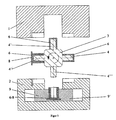
- fig. 1 shows a tool not being according to the invention in its first cycle of four phases seen from above in closed position,
- fig. 2 shows the same in a following cycle also seen from above in closed position,
- fig. 3 shows the same in open position, where the turning of 90 degrees in the direction of the arrows can take place,
- fig. 4 shows the same, where the jaws also are opened so that the finished combined parts are released,
- fig. 5 shows one for the inserting intended tool according to the invention with two turnable middle sections seen from above in closed position, and
- fig. 6 the same in open position.
- In fig. 1 are shown a tool not being according to the invention for the two-component molding with the
stationary mold part 1, themovable mold part 2 and theturnable middle section 3. On theturnable middle section 3 there is on each of the four sides placed a core, which positions in the four phases of the molding, respectively, are marked as 4, 4', 4" and 4'''. In the beginning of the first phase a core is placed inposition 4 at the right and situated in thecavity 5 between thestationary mold part 1 and themovable mold part 2. In the second phase the placing of the core is in thetop position 4', where there in the mold cavity is molded theinner piece 6 of the part. In the third phase, where the core is in aposition 4" at the left on the figure, themolded piece 6 of the part is still placed on it. The molded and cooledpiece 6 of the part now serves as a part of the mold, namely as the inner parting line of the cavity for thenext piece 8 of the part in connection with theouter mold cavity 7. In the fourth and the last phase of the start, in which the core is in itslowest position 4"', the final molding of thenext piece 8 of the part has taken place in theouter mold cavity 7. In themovable mold part 2 are noticed the twojaw parts 9 and 9', which at their later opening makes the ejection of the then complete molded combined part 6-8 possible, but which here has caught and still is holding this. But as it will be seen from the figure, there is plenty of space for placing e. g. hot runners, preferably in thestationary mould part 1 as in the ordinary molding tools. - Fig. 2 shows the same tool in closed position in one of the cycles that follows after the first cycle shown on fig. 1. In the phase to the right on the core there is in the mould cavity molded the innermost placed
piece 6 of the parts. In the top position thispiece 6 of the parts is cooled so that it in the phase at the left, where the position of the core is 4", can serve as a part of the mould outline for the final molding of thenext piece 8 of the part. In the phase at the lowest point of the figure with the core inposition 4''' is seen the finished molded combined part 6-8 ready for ejection by the use of the two built injaw parts 9 and 9'. - On fig. 3 is shown the same tool in open position, where the
turnable middle section 3 is able to perform its repeated 90 degrees turnings. It concerns the same four phases with therespective placements lowest position 4''' is the finished molded combined part 6-8 removed from its core by the use of the twojaws 9 and 9' which is not yet opened. In this way it is avoided to place any ejectors in themiddle section 3 and maybe completely avoiding the use of ejectors in the tool. This design is a great simplifying of the construction of the tool, as well as the opening distance and the build-in height in this way can be minimized in relation to tools with traditional ejectors. But in other cases more traditional ejectors can be used to the tools according to the invention. - Fig. 4 shows the same tool in open position, where the difference from fig. 3 is that the
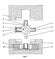
jaws 9 and 9' are opened, so that the final ejection of the finished combined part 6-8 has been able to take place. This can e. g. be realized by the ejectors (not shown in the drawings) being placed under thejaws 9 and 9' or by using compressed air. - On the fig. 5 is from above shown a solution according to the invention, namely where the tool according to the invention is used for the insertion of e. g. metal parts. In the closed tool consisting of the
stationary mold part 11 and themovable mold part 12 is shown the two uniformturnable middle sections 13 and 13', which here rotates in opposite directions for the benefit of the balance of the mold. If only the upper part of the middle section is considered you see in the lowest phase theempty mold cavity 15 in themiddle section 13. In the next phase at the left on the figure thismold cavity 15 serves in connection with thecore 14 from themold part 11 for the molding of thefirst piece 16 of the plastic part. In the upper phase thepart 10 to be inserted is added to thepiece 16. This can take place while the mold is still closed, which saves time. In the last phase at the right is thelast piece 18 of the plastic part molded on, so that themetal part 10 now is firmly encapsulated in the plastic. - In fig. 6 is shown the same tool in open position where the finished in-molded
part - That on figs. 5 and 6 of the drawings shown is only an example of how this invention can be transformed into functioning tools. A long row of other designs of the tool according to the invention can be imagined, but the shown example should be sufficient to show the fundamental principles of the invention.
Claims (6)
- Method for production of parts (16,18,10) preferably of plastics, both one-component as well as multi-component, in a tool equipped with a stationary mold part (11), a movable mold part (12) and at least one turnable middle section (13) turnable about an axis being perpendicular to the closing direction of the tool and having a cross-section with an outline of a polygon with pairs of mutually parallel opposite sides, the tool having an open position and a closed position, in which latter position one of the pairs of mutually parallel sides of the turnable middle section is placed at a right angle to the closing direction of the tool and another pair of mutually parallel sides of the turnable middle section is not placed at a right angle to the closing direction of the tool, the turnable middle section (13) being supplied with material by inserting a special part (10) at at least one of the sides of the turnable middle section (13), which is not placed at a right angle to the closing direction of the tool, the inserting taking place while the tool is in its closed position.
- Method according to claim 1, characterized in that the inserting takes place on at least two non-mutually parallel sides of the turnable middle section (13).
- Method according to at least one of the previous claims, characterized in that the inserting takes place on two substantially mutually parallel sides of the turnable middle section (13).
- Method according to at least one of the previous claims, characterized in that the corners of the polygonal cross-sectional outline of the middle section are cut off to minimize the opening movement of the tool.
- Method according to at least one of the previous claims, characterized in that in a first molding operation the turnable middle section (13) and the stationary mold part (12) provide a piece (16) of a part adapted to receive a part (10) to be inserted and retain the latter under a following molding operation of a locking piece (18).
- Method according to at least one of the previous claims, characterized in that the turnable middle section (3) is designed in such a way that parts (10) intended for insertion are supplied at more than one station, preferably with moldings in between.
Priority Applications (3)
| Application Number | Priority Date | Filing Date | Title |
|---|---|---|---|
| EP06016162A EP1738890B1 (en) | 1999-05-17 | 2000-05-15 | Mould with turnable middle section |
| DK00926724T DK1237701T3 (en) | 1999-05-17 | 2000-05-15 | Tool with swivel center section |
| DK06016162.7T DK1738890T3 (en) | 1999-05-17 | 2000-05-15 | Swivel center section tool |
Applications Claiming Priority (3)
| Application Number | Priority Date | Filing Date | Title |
|---|---|---|---|
| DKPA199900670 | 1999-05-17 | ||
| DK67099 | 1999-05-17 | ||
| PCT/DK2000/000261 WO2000073040A1 (en) | 1999-05-17 | 2000-05-15 | Mould with turnable middle section |
Related Child Applications (1)
| Application Number | Title | Priority Date | Filing Date |
|---|---|---|---|
| EP06016162A Division EP1738890B1 (en) | 1999-05-17 | 2000-05-15 | Mould with turnable middle section |
Publications (2)
| Publication Number | Publication Date |
|---|---|
| EP1237701A1 EP1237701A1 (en) | 2002-09-11 |
| EP1237701B1 true EP1237701B1 (en) | 2006-08-23 |
Family
ID=8096201
Family Applications (2)
| Application Number | Title | Priority Date | Filing Date |
|---|---|---|---|
| EP00926724A Revoked EP1237701B1 (en) | 1999-05-17 | 2000-05-15 | Mould with turnable middle section |
| EP06016162A Expired - Lifetime EP1738890B1 (en) | 1999-05-17 | 2000-05-15 | Mould with turnable middle section |
Family Applications After (1)
| Application Number | Title | Priority Date | Filing Date |
|---|---|---|---|
| EP06016162A Expired - Lifetime EP1738890B1 (en) | 1999-05-17 | 2000-05-15 | Mould with turnable middle section |
Country Status (15)
| Country | Link |
|---|---|
| US (2) | US7150845B1 (en) |
| EP (2) | EP1237701B1 (en) |
| JP (1) | JP4789325B2 (en) |
| KR (1) | KR100656114B1 (en) |
| CN (1) | CN1139473C (en) |
| AT (2) | ATE337154T1 (en) |
| AU (1) | AU4537800A (en) |
| BR (1) | BR0010744B1 (en) |
| CA (1) | CA2375668A1 (en) |
| DE (2) | DE60043756D1 (en) |
| DK (2) | DK1738890T3 (en) |
| ES (1) | ES2270826T3 (en) |
| MX (1) | MXPA01011723A (en) |
| PT (1) | PT1237701E (en) |
| WO (1) | WO2000073040A1 (en) |
Cited By (3)
| Publication number | Priority date | Publication date | Assignee | Title |
|---|---|---|---|---|
| US7998390B2 (en) | 2008-04-15 | 2011-08-16 | Mold-Masters (2007) Limited | Multi-material injection molding apparatus and method |
| US8113820B2 (en) | 2006-06-13 | 2012-02-14 | Electroform Company, Inc. | Method and apparatus for molding and assembling plural-part plastic assemblies |
| DE102011017040A1 (en) | 2011-04-14 | 2012-10-18 | Awm Mold Tech Ag | Method for producing a coated molding and devices therefor |
Families Citing this family (33)
| Publication number | Priority date | Publication date | Assignee | Title |
|---|---|---|---|---|
| ATE483570T1 (en) | 2000-10-26 | 2010-10-15 | Jes Tougaard Gram | METHOD FOR SHAPING AND ASSEMBLY AN ASSEMBLED OBJECT |
| US6682678B2 (en) | 2002-02-04 | 2004-01-27 | Arrow Innovations, Llc | Method of making translational spout closure for a container |
| WO2004071568A1 (en) | 2003-02-12 | 2004-08-26 | Unomedical A/S | A medical connector and a method of injection moulding such a connector |
| WO2004103676A2 (en) * | 2003-05-22 | 2004-12-02 | Foboha Gmbh Formenbau | Method and device for the production of multi-part objects |
| US20050227043A1 (en) * | 2004-04-08 | 2005-10-13 | Lear Corporation | Two-shot polymeric component with wrapped edge and a method of producing same |
| DE102004032362A1 (en) * | 2004-07-03 | 2006-01-26 | Rehau Ag + Co | Method for producing a composite component and composite component |
| US20060118999A1 (en) * | 2004-12-06 | 2006-06-08 | Bayer Materialscience Llc | Method of preparing a coated molded article |
| US7314590B2 (en) | 2005-09-20 | 2008-01-01 | Bayer Materialscience Llc | Method of preparing a coated molded plastic article |
| DE102006016200A1 (en) * | 2006-04-06 | 2007-10-11 | Krauss-Maffei Kunststofftechnik Gmbh | Method and device for producing multi-component plastic molded parts |
| DE102006021021A1 (en) | 2006-05-05 | 2007-11-15 | Krauss Maffei Gmbh | Process for producing a multi-layer part |
| DE102007002368A1 (en) * | 2007-01-17 | 2008-07-31 | Schoeller Arca Systems Services Gmbh | Plastic case i.e. bottle case, has strips formed with same color as plastic material of base body in lateral edge regions and adhesively connected with plastic material for forming strap by injecting plastic |
| JP2008235489A (en) * | 2007-03-19 | 2008-10-02 | Fujitsu Ltd | Resin-sealing method, mold for resin sealing, and resin-sealing apparatus |
| CN101616556B (en) * | 2008-06-27 | 2011-08-31 | 深圳富泰宏精密工业有限公司 | Housing of electronic device and manufacturing method thereof |
| NO336476B1 (en) | 2009-03-11 | 2015-09-07 | Mezonic As | A method and plant for producing a storage container for storing nuclear radiation material |
| FR2945235B1 (en) * | 2009-05-11 | 2015-08-21 | Moulindustrie | KIT FOR A MOLDING MACHINE BY INJECTING MOLDED PARTS. |
| US20100313424A1 (en) | 2009-06-11 | 2010-12-16 | Robert Harold Johnson | Blade cartridge guard comprising an array of flexible fins extending in multiple directions |
| US20100319198A1 (en) * | 2009-06-17 | 2010-12-23 | Robert Harold Johnson | Blade cartridge guard comprising an array of flexible fins having varying stiffness |
| CN101966742A (en) * | 2009-07-27 | 2011-02-09 | 康佳集团股份有限公司 | Multicolor injection mould device |
| CN101966743B (en) * | 2009-07-27 | 2015-04-29 | 康佳集团股份有限公司 | Injection mould device |
| CH702442A1 (en) | 2009-12-16 | 2011-06-30 | Foboha Gmbh Formenbau | A method for producing a multi-component plastic molded part by means of injection molding and injection molding device for performing the method. |
| US8931176B2 (en) | 2010-06-09 | 2015-01-13 | The Gillette Company | Blade cartridge guard comprising an array of flexible fins extending in multiple directions |
| CH705141A2 (en) * | 2011-06-30 | 2012-12-31 | Foboha Gmbh Formenbau | Device and method for the production of injection molded parts with different components. |
| CH705593A2 (en) * | 2011-10-04 | 2013-04-15 | Eta Sa Mft Horlogere Suisse | Forming transparent component of watch, by affixing decorations on sides of component having upper surface and lower dug, depositing first decoration on male model and first station, and depositing second decoration on second station |
| AT514019B1 (en) | 2013-04-02 | 2015-02-15 | Engel Austria Gmbh | Method and device for producing an injection-molded part |
| DE102013006713A1 (en) | 2013-04-19 | 2014-10-23 | Otto Männer Innovation GmbH | Multi-shot injection molding device |
| JP6174789B2 (en) | 2013-05-13 | 2017-08-02 | アイエムフラックス インコーポレイテッド | Low constant pressure injection molding system with variable position mold cavity |
| DE112014003601T5 (en) | 2013-08-05 | 2016-06-02 | Dbm Reflex Enterprises Inc. | Injected thick lens |
| US11241544B2 (en) | 2013-12-05 | 2022-02-08 | Novo Nordisk A/S | Housing for a medical injection device |
| FR3017323B1 (en) * | 2014-02-11 | 2016-02-26 | Groupe Jbt | PROCESS FOR MANUFACTURING POLYMER PARTS BY INJECTION IN CAVITY AND ASSOCIATED SYSTEM |
| GB201501940D0 (en) * | 2015-02-05 | 2015-03-25 | Obrist Closures Switzerland | A method of forming a closure |
| US10799644B2 (en) | 2015-06-01 | 2020-10-13 | Novo Nordisk A/S | Method for moulding a polymeric housing for a medical injection device |
| WO2018001986A1 (en) * | 2016-06-27 | 2018-01-04 | Foboha (Germany) Gmbh | Method and device for making of aseptic blood bags and the like |
| KR102395643B1 (en) * | 2022-03-04 | 2022-05-09 | 에스디(주) | Jig for actuator housing insert injection molding |
Citations (1)
| Publication number | Priority date | Publication date | Assignee | Title |
|---|---|---|---|---|
| JPS63135214A (en) * | 1986-11-28 | 1988-06-07 | Hashimoto Forming Co Ltd | Manufacture of decorative molding |
Family Cites Families (28)
| Publication number | Priority date | Publication date | Assignee | Title |
|---|---|---|---|---|
| NL276020A (en) | 1962-03-16 | |||
| US3707591A (en) * | 1971-07-02 | 1972-12-26 | Trans Container Corp | High speed molding of hollow plastic articles |
| US3985485A (en) * | 1974-06-03 | 1976-10-12 | Consupak, Inc. | Blow molding apparatus with multiple cycle core rods |
| JPS5854662B2 (en) * | 1979-01-17 | 1983-12-06 | 株式会社日本製鋼所 | Assembly type injection molding equipment |
| US4243362A (en) * | 1979-06-04 | 1981-01-06 | Globe-Union Inc. | Composite molding apparatus for articles from two materials having a rotary mold block which includes pins for providing core areas |
| US4449913A (en) * | 1981-02-23 | 1984-05-22 | The Continental Group, Inc. | Rotary injection turret for the making of preforms |
| US4444711A (en) * | 1981-12-21 | 1984-04-24 | Husky Injection Molding Systems Ltd. | Method of operating a two-shot injection-molding machine |
| JPS5952626A (en) * | 1982-09-17 | 1984-03-27 | Sumitomo Chem Co Ltd | Molding method |
| JPS61122819U (en) * | 1985-01-22 | 1986-08-02 | ||
| GB8517073D0 (en) * | 1985-07-05 | 1985-08-14 | Hepworth Iron Co Ltd | Pipe pipe couplings &c |
| US6555037B1 (en) * | 1985-08-19 | 2003-04-29 | Payne Leroy | Multiaxis rotational molding method and apparatus |
| DE3620175A1 (en) | 1986-06-14 | 1987-12-17 | Kloeckner Ferromatik Desma | INJECTION MOLDING MACHINE WITH AT LEAST TWO PLASTIFICATION AND INJECTION UNITS |
| JPH0798341B2 (en) * | 1986-11-28 | 1995-10-25 | 橋本フオ−ミング工業株式会社 | Manufacturing method of decorative molded products |
| US4885121A (en) * | 1987-08-03 | 1989-12-05 | Chemcast Corporation | Method of making a dual durometer self-locking and sealing plug |
| JPH01114405A (en) * | 1987-10-28 | 1989-05-08 | Taigaasu Polymer Kk | Electromagnetic wave shielding case and its production |
| US4836767A (en) * | 1987-11-25 | 1989-06-06 | Husky Injection Molding System, Ltd. | Swing plate molding machine |
| JPH0692095B2 (en) * | 1988-11-25 | 1994-11-16 | スタンレー電気株式会社 | Molding method for multicolor molded products |
| US5030406A (en) * | 1989-08-14 | 1991-07-09 | Sorensen Jens Ole | Sequentially injected multi-component shuttle-stack-molding |
| US5169655A (en) * | 1990-06-04 | 1992-12-08 | Von Holdt Sr John W | Multiple cavity injection mold |
| JPH08108449A (en) * | 1994-10-11 | 1996-04-30 | Eiichi Tsunoda | Multicolor molding method |
| US5582788A (en) * | 1994-12-28 | 1996-12-10 | Continental Pet Technologies, Inc. | Method of cooling multilayer preforms |
| JP2997875B2 (en) * | 1996-11-19 | 2000-01-11 | 博敏 西田 | Injection molding method for resin molding |
| DE69826526T2 (en) * | 1997-01-29 | 2005-11-17 | Jes Tougaard Gram | METHOD AND DEVICE FOR FORMING A COMPOSITE OBJECT |
| EP1027199A1 (en) * | 1997-02-25 | 2000-08-16 | Jes Tougaard Gram | Procedure and machine for multi component moulding |
| US6143227A (en) * | 1997-07-30 | 2000-11-07 | Visteon Global Technologies, Inc. | Method for injection molding an article having film covered flanges |
| US6086808A (en) * | 1997-08-19 | 2000-07-11 | Universal Ventures | Repositioning of articles between different positions within an intermittently accessible space |
| DE19911729B4 (en) * | 1999-03-16 | 2007-01-11 | Aisa Automation Industrielle S.A. | Method and device for producing a two-chamber tube |
| US6447280B1 (en) * | 2000-09-29 | 2002-09-10 | Tech Mold, Inc. | Dual manifold mold with rotating center plate |
-
2000
- 2000-05-15 DK DK06016162.7T patent/DK1738890T3/en active
- 2000-05-15 KR KR1020017014648A patent/KR100656114B1/en not_active IP Right Cessation
- 2000-05-15 BR BRPI0010744-1A patent/BR0010744B1/en not_active IP Right Cessation
- 2000-05-15 DE DE60043756T patent/DE60043756D1/en not_active Expired - Lifetime
- 2000-05-15 EP EP00926724A patent/EP1237701B1/en not_active Revoked
- 2000-05-15 CA CA002375668A patent/CA2375668A1/en not_active Abandoned
- 2000-05-15 PT PT00926724T patent/PT1237701E/en unknown
- 2000-05-15 WO PCT/DK2000/000261 patent/WO2000073040A1/en active IP Right Grant
- 2000-05-15 CN CNB008075972A patent/CN1139473C/en not_active Expired - Lifetime
- 2000-05-15 AT AT00926724T patent/ATE337154T1/en not_active IP Right Cessation
- 2000-05-15 EP EP06016162A patent/EP1738890B1/en not_active Expired - Lifetime
- 2000-05-15 MX MXPA01011723A patent/MXPA01011723A/en unknown
- 2000-05-15 AU AU45378/00A patent/AU4537800A/en not_active Abandoned
- 2000-05-15 AT AT06016162T patent/ATE455637T1/en active
- 2000-05-15 DK DK00926724T patent/DK1237701T3/en active
- 2000-05-15 US US09/979,687 patent/US7150845B1/en not_active Expired - Fee Related
- 2000-05-15 DE DE60030320T patent/DE60030320T2/en not_active Expired - Fee Related
- 2000-05-15 ES ES00926724T patent/ES2270826T3/en not_active Expired - Lifetime
- 2000-05-15 JP JP2000621135A patent/JP4789325B2/en not_active Expired - Lifetime
-
2006
- 2006-12-19 US US11/641,515 patent/US7608212B2/en not_active Expired - Fee Related
Patent Citations (1)
| Publication number | Priority date | Publication date | Assignee | Title |
|---|---|---|---|---|
| JPS63135214A (en) * | 1986-11-28 | 1988-06-07 | Hashimoto Forming Co Ltd | Manufacture of decorative molding |
Cited By (4)
| Publication number | Priority date | Publication date | Assignee | Title |
|---|---|---|---|---|
| US8113820B2 (en) | 2006-06-13 | 2012-02-14 | Electroform Company, Inc. | Method and apparatus for molding and assembling plural-part plastic assemblies |
| US7998390B2 (en) | 2008-04-15 | 2011-08-16 | Mold-Masters (2007) Limited | Multi-material injection molding apparatus and method |
| DE102011017040A1 (en) | 2011-04-14 | 2012-10-18 | Awm Mold Tech Ag | Method for producing a coated molding and devices therefor |
| WO2012139977A2 (en) | 2011-04-14 | 2012-10-18 | Kraussmaffei Technologies Gmbh | Process for producing a coated moulding and apparatuses therefor |
Also Published As
| Publication number | Publication date |
|---|---|
| DE60030320D1 (en) | 2006-10-05 |
| US7150845B1 (en) | 2006-12-19 |
| DE60030320T2 (en) | 2007-03-29 |
| EP1237701A1 (en) | 2002-09-11 |
| BR0010744A (en) | 2002-02-13 |
| DE60043756D1 (en) | 2010-03-11 |
| CN1139473C (en) | 2004-02-25 |
| BR0010744B1 (en) | 2011-01-25 |
| DK1738890T3 (en) | 2010-05-25 |
| KR100656114B1 (en) | 2006-12-11 |
| KR20020010661A (en) | 2002-02-04 |
| JP4789325B2 (en) | 2011-10-12 |
| MXPA01011723A (en) | 2002-11-04 |
| US20070096361A1 (en) | 2007-05-03 |
| ES2270826T3 (en) | 2007-04-16 |
| JP2003500254A (en) | 2003-01-07 |
| EP1738890B1 (en) | 2010-01-20 |
| DK1237701T3 (en) | 2006-12-04 |
| PT1237701E (en) | 2007-01-31 |
| ATE337154T1 (en) | 2006-09-15 |
| CA2375668A1 (en) | 2000-12-07 |
| CN1350482A (en) | 2002-05-22 |
| US7608212B2 (en) | 2009-10-27 |
| EP1738890A1 (en) | 2007-01-03 |
| AU4537800A (en) | 2000-12-18 |
| WO2000073040A1 (en) | 2000-12-07 |
| ATE455637T1 (en) | 2010-02-15 |
Similar Documents
| Publication | Publication Date | Title |
|---|---|---|
| EP1237701B1 (en) | Mould with turnable middle section | |
| US7081222B2 (en) | Procedure and machinery for the molding and assembling of an assembled object | |
| US6783346B2 (en) | Device for manufacturing articles made of plastic | |
| US6210619B1 (en) | Method for manufacturing a two-piece plastic assembly | |
| JP4104021B1 (en) | Manufacturing method of two-color molded products | |
| CN108124435A (en) | For the blowing mold of blowing thermoplastic containers | |
| US7585447B2 (en) | Tool with closing mechanism and method of manufacturing preferably plastic parts with hinges | |
| US20060099297A1 (en) | Concurrent cooling mold | |
| WO2022249725A1 (en) | Mold for injection molding, injection molding device, and injection molding method | |
| JP3047212B2 (en) | Molding method and molding die for laminated molded article | |
| EP4271548A1 (en) | A mold tool for injection molding | |
| JP2000317989A (en) | Injection mold and production thereof | |
| WO2009053503A1 (en) | A multipoint sequential injection system for manufacturing sheets of thermoplastic polyurethane |
Legal Events
| Date | Code | Title | Description |
|---|---|---|---|
| PUAI | Public reference made under article 153(3) epc to a published international application that has entered the european phase |
Free format text: ORIGINAL CODE: 0009012 |
|
| 17P | Request for examination filed |
Effective date: 20011214 |
|
| AK | Designated contracting states |
Kind code of ref document: A1 Designated state(s): AT BE CH CY DE DK ES FI FR GB GR IE IT LI LU MC NL PT SE |
|
| 17Q | First examination report despatched |
Effective date: 20040325 |
|
| GRAP | Despatch of communication of intention to grant a patent |
Free format text: ORIGINAL CODE: EPIDOSNIGR1 |
|
| GRAC | Information related to communication of intention to grant a patent modified |
Free format text: ORIGINAL CODE: EPIDOSCIGR1 |
|
| GRAS | Grant fee paid |
Free format text: ORIGINAL CODE: EPIDOSNIGR3 |
|
| GRAA | (expected) grant |
Free format text: ORIGINAL CODE: 0009210 |
|
| AK | Designated contracting states |
Kind code of ref document: B1 Designated state(s): AT BE CH CY DE DK ES FI FR GB GR IE IT LI LU MC NL PT SE |
|
| PG25 | Lapsed in a contracting state [announced via postgrant information from national office to epo] |
Ref country code: IT Free format text: LAPSE BECAUSE OF FAILURE TO SUBMIT A TRANSLATION OF THE DESCRIPTION OR TO PAY THE FEE WITHIN THE PRESCRIBED TIME-LIMIT;WARNING: LAPSES OF ITALIAN PATENTS WITH EFFECTIVE DATE BEFORE 2007 MAY HAVE OCCURRED AT ANY TIME BEFORE 2007. THE CORRECT EFFECTIVE DATE MAY BE DIFFERENT FROM THE ONE RECORDED. Effective date: 20060823 Ref country code: FI Free format text: LAPSE BECAUSE OF FAILURE TO SUBMIT A TRANSLATION OF THE DESCRIPTION OR TO PAY THE FEE WITHIN THE PRESCRIBED TIME-LIMIT Effective date: 20060823 |
|
| REG | Reference to a national code |
Ref country code: GB Ref legal event code: FG4D |
|
| REG | Reference to a national code |
Ref country code: CH Ref legal event code: EP |
|
| REG | Reference to a national code |
Ref country code: IE Ref legal event code: FG4D |
|
| REF | Corresponds to: |
Ref document number: 60030320 Country of ref document: DE Date of ref document: 20061005 Kind code of ref document: P |
|
| REG | Reference to a national code |
Ref country code: DK Ref legal event code: T3 |
|
| REG | Reference to a national code |
Ref country code: SE Ref legal event code: TRGR |
|
| REG | Reference to a national code |
Ref country code: CH Ref legal event code: NV Representative=s name: ROTTMANN, ZIMMERMANN + PARTNER AG |
|
| REG | Reference to a national code |
Ref country code: PT Ref legal event code: SC4A Free format text: AVAILABILITY OF NATIONAL TRANSLATION Effective date: 20061123 |
|
| ET | Fr: translation filed | ||
| REG | Reference to a national code |
Ref country code: ES Ref legal event code: FG2A Ref document number: 2270826 Country of ref document: ES Kind code of ref document: T3 |
|
| PLBI | Opposition filed |
Free format text: ORIGINAL CODE: 0009260 |
|
| 26 | Opposition filed |
Opponent name: FOBOHA GMBH FORMENBAU Effective date: 20070523 |
|
| PLAX | Notice of opposition and request to file observation + time limit sent |
Free format text: ORIGINAL CODE: EPIDOSNOBS2 |
|
| NLR1 | Nl: opposition has been filed with the epo |
Opponent name: FOBOHA GMBH FORMENBAU |
|
| PLAF | Information modified related to communication of a notice of opposition and request to file observations + time limit |
Free format text: ORIGINAL CODE: EPIDOSCOBS2 |
|
| PLBB | Reply of patent proprietor to notice(s) of opposition received |
Free format text: ORIGINAL CODE: EPIDOSNOBS3 |
|
| PG25 | Lapsed in a contracting state [announced via postgrant information from national office to epo] |
Ref country code: MC Free format text: LAPSE BECAUSE OF NON-PAYMENT OF DUE FEES Effective date: 20070531 |
|
| PG25 | Lapsed in a contracting state [announced via postgrant information from national office to epo] |
Ref country code: GR Free format text: LAPSE BECAUSE OF FAILURE TO SUBMIT A TRANSLATION OF THE DESCRIPTION OR TO PAY THE FEE WITHIN THE PRESCRIBED TIME-LIMIT Effective date: 20061124 |
|
| PGFP | Annual fee paid to national office [announced via postgrant information from national office to epo] |
Ref country code: CH Payment date: 20080527 Year of fee payment: 9 Ref country code: DE Payment date: 20080522 Year of fee payment: 9 Ref country code: DK Payment date: 20080526 Year of fee payment: 9 Ref country code: ES Payment date: 20080521 Year of fee payment: 9 |
|
| PGFP | Annual fee paid to national office [announced via postgrant information from national office to epo] |
Ref country code: AT Payment date: 20080522 Year of fee payment: 9 |
|
| APBM | Appeal reference recorded |
Free format text: ORIGINAL CODE: EPIDOSNREFNO |
|
| APBP | Date of receipt of notice of appeal recorded |
Free format text: ORIGINAL CODE: EPIDOSNNOA2O |
|
| APAH | Appeal reference modified |
Free format text: ORIGINAL CODE: EPIDOSCREFNO |
|
| PGFP | Annual fee paid to national office [announced via postgrant information from national office to epo] |
Ref country code: IT Payment date: 20080526 Year of fee payment: 9 Ref country code: PT Payment date: 20080422 Year of fee payment: 9 Ref country code: BE Payment date: 20080529 Year of fee payment: 9 |
|
| PGFP | Annual fee paid to national office [announced via postgrant information from national office to epo] |
Ref country code: IE Payment date: 20080521 Year of fee payment: 9 Ref country code: NL Payment date: 20080531 Year of fee payment: 9 Ref country code: SE Payment date: 20080520 Year of fee payment: 9 |
|
| APBQ | Date of receipt of statement of grounds of appeal recorded |
Free format text: ORIGINAL CODE: EPIDOSNNOA3O |
|
| PG25 | Lapsed in a contracting state [announced via postgrant information from national office to epo] |
Ref country code: CY Free format text: LAPSE BECAUSE OF FAILURE TO SUBMIT A TRANSLATION OF THE DESCRIPTION OR TO PAY THE FEE WITHIN THE PRESCRIBED TIME-LIMIT Effective date: 20060823 Ref country code: LU Free format text: LAPSE BECAUSE OF NON-PAYMENT OF DUE FEES Effective date: 20070515 |
|
| REG | Reference to a national code |
Ref country code: PT Ref legal event code: MM4A Free format text: LAPSE DUE TO NON-PAYMENT OF FEES Effective date: 20091116 |
|
| BERE | Be: lapsed |
Owner name: GRAM, JES TOUGAARD Effective date: 20090531 |
|
| REG | Reference to a national code |
Ref country code: CH Ref legal event code: PL |
|
| REG | Reference to a national code |
Ref country code: DK Ref legal event code: EBP |
|
| PG25 | Lapsed in a contracting state [announced via postgrant information from national office to epo] |
Ref country code: AT Free format text: LAPSE BECAUSE OF NON-PAYMENT OF DUE FEES Effective date: 20090515 Ref country code: LI Free format text: LAPSE BECAUSE OF NON-PAYMENT OF DUE FEES Effective date: 20090531 Ref country code: CH Free format text: LAPSE BECAUSE OF NON-PAYMENT OF DUE FEES Effective date: 20090531 |
|
| NLV4 | Nl: lapsed or anulled due to non-payment of the annual fee |
Effective date: 20091201 |
|
| PG25 | Lapsed in a contracting state [announced via postgrant information from national office to epo] |
Ref country code: NL Free format text: LAPSE BECAUSE OF NON-PAYMENT OF DUE FEES Effective date: 20091201 |
|
| REG | Reference to a national code |
Ref country code: FR Ref legal event code: ST Effective date: 20100129 |
|
| PG25 | Lapsed in a contracting state [announced via postgrant information from national office to epo] |
Ref country code: PT Free format text: LAPSE BECAUSE OF NON-PAYMENT OF DUE FEES Effective date: 20091116 |
|
| PG25 | Lapsed in a contracting state [announced via postgrant information from national office to epo] |
Ref country code: FR Free format text: LAPSE BECAUSE OF NON-PAYMENT OF DUE FEES Effective date: 20090602 Ref country code: DK Free format text: LAPSE BECAUSE OF NON-PAYMENT OF DUE FEES Effective date: 20090531 Ref country code: IE Free format text: LAPSE BECAUSE OF NON-PAYMENT OF DUE FEES Effective date: 20090515 |
|
| PGFP | Annual fee paid to national office [announced via postgrant information from national office to epo] |
Ref country code: FR Payment date: 20080430 Year of fee payment: 9 Ref country code: GB Payment date: 20091130 Year of fee payment: 10 |
|
| PG25 | Lapsed in a contracting state [announced via postgrant information from national office to epo] |
Ref country code: BE Free format text: LAPSE BECAUSE OF NON-PAYMENT OF DUE FEES Effective date: 20090531 Ref country code: DE Free format text: LAPSE BECAUSE OF NON-PAYMENT OF DUE FEES Effective date: 20091201 |
|
| REG | Reference to a national code |
Ref country code: ES Ref legal event code: FD2A Effective date: 20090516 |
|
| PG25 | Lapsed in a contracting state [announced via postgrant information from national office to epo] |
Ref country code: ES Free format text: LAPSE BECAUSE OF NON-PAYMENT OF DUE FEES Effective date: 20090516 |
|
| GBPC | Gb: european patent ceased through non-payment of renewal fee |
Effective date: 20100515 |
|
| PG25 | Lapsed in a contracting state [announced via postgrant information from national office to epo] |
Ref country code: IT Free format text: LAPSE BECAUSE OF NON-PAYMENT OF DUE FEES Effective date: 20090515 |
|
| PG25 | Lapsed in a contracting state [announced via postgrant information from national office to epo] |
Ref country code: SE Free format text: LAPSE BECAUSE OF NON-PAYMENT OF DUE FEES Effective date: 20090516 |
|
| PG25 | Lapsed in a contracting state [announced via postgrant information from national office to epo] |
Ref country code: GB Free format text: LAPSE BECAUSE OF NON-PAYMENT OF DUE FEES Effective date: 20100515 |
|
| APAR | Information on invitation to file observation in appeal modified |
Free format text: ORIGINAL CODE: EPIDOSCOBA2O |
|
| APBU | Appeal procedure closed |
Free format text: ORIGINAL CODE: EPIDOSNNOA9O |
|
| PLAB | Opposition data, opponent's data or that of the opponent's representative modified |
Free format text: ORIGINAL CODE: 0009299OPPO |
|
| R26 | Opposition filed (corrected) |
Opponent name: FOBOHA GMBH FORMENBAU Effective date: 20070523 |
|
| RDAF | Communication despatched that patent is revoked |
Free format text: ORIGINAL CODE: EPIDOSNREV1 |
|
| RDAG | Patent revoked |
Free format text: ORIGINAL CODE: 0009271 |
|
| STAA | Information on the status of an ep patent application or granted ep patent |
Free format text: STATUS: PATENT REVOKED |
|
| 27W | Patent revoked |
Effective date: 20121117 |
|
| REG | Reference to a national code |
Ref country code: AT Ref legal event code: MA03 Ref document number: 337154 Country of ref document: AT Kind code of ref document: T Effective date: 20121117 |
|
| REG | Reference to a national code |
Ref country code: SE Ref legal event code: ECNC |