EP1237494B9 - Drape for multiple-tiered sterile hospital surface - Google Patents
Drape for multiple-tiered sterile hospital surface Download PDFInfo
- Publication number
- EP1237494B9 EP1237494B9 EP99963054A EP99963054A EP1237494B9 EP 1237494 B9 EP1237494 B9 EP 1237494B9 EP 99963054 A EP99963054 A EP 99963054A EP 99963054 A EP99963054 A EP 99963054A EP 1237494 B9 EP1237494 B9 EP 1237494B9
- Authority
- EP
- European Patent Office
- Prior art keywords
- drape
- tier
- section
- lower tier
- sterile
- Prior art date
- Legal status (The legal status is an assumption and is not a legal conclusion. Google has not performed a legal analysis and makes no representation as to the accuracy of the status listed.)
- Expired - Lifetime
Links
- 239000000463 material Substances 0.000 claims description 11
- 238000000034 method Methods 0.000 description 8
- -1 polyethylene Polymers 0.000 description 5
- 239000007788 liquid Substances 0.000 description 4
- 238000012800 visualization Methods 0.000 description 4
- 239000004698 Polyethylene Substances 0.000 description 3
- 229920000573 polyethylene Polymers 0.000 description 3
- 229920001131 Pulp (paper) Polymers 0.000 description 1
- 238000010276 construction Methods 0.000 description 1
- 238000011109 contamination Methods 0.000 description 1
- 238000009963 fulling Methods 0.000 description 1
- 230000002401 inhibitory effect Effects 0.000 description 1
- 230000013011 mating Effects 0.000 description 1
- 239000002184 metal Substances 0.000 description 1
- 239000004745 nonwoven fabric Substances 0.000 description 1
- 230000008520 organization Effects 0.000 description 1
- 239000004033 plastic Substances 0.000 description 1
- 229920003023 plastic Polymers 0.000 description 1
- 230000001681 protective effect Effects 0.000 description 1
Images
Classifications
-
- A—HUMAN NECESSITIES
- A61—MEDICAL OR VETERINARY SCIENCE; HYGIENE
- A61B—DIAGNOSIS; SURGERY; IDENTIFICATION
- A61B46/00—Surgical drapes
- A61B46/10—Surgical drapes specially adapted for instruments, e.g. microscopes
-
- A—HUMAN NECESSITIES
- A61—MEDICAL OR VETERINARY SCIENCE; HYGIENE
- A61B—DIAGNOSIS; SURGERY; IDENTIFICATION
- A61B50/00—Containers, covers, furniture or holders specially adapted for surgical or diagnostic appliances or instruments, e.g. sterile covers
- A61B50/10—Furniture specially adapted for surgical or diagnostic appliances or instruments
- A61B50/15—Mayo stands; Tables
-
- A—HUMAN NECESSITIES
- A61—MEDICAL OR VETERINARY SCIENCE; HYGIENE
- A61B—DIAGNOSIS; SURGERY; IDENTIFICATION
- A61B50/00—Containers, covers, furniture or holders specially adapted for surgical or diagnostic appliances or instruments, e.g. sterile covers
- A61B50/10—Furniture specially adapted for surgical or diagnostic appliances or instruments
Definitions
- the present invention relates to sterile surface covers, and, more particularly, to drapes for tables in operating rooms.
- a surface that is to hold instruments such as a metal table
- a sterile drape such as are known in the art.
- the surface of the table itself is considered non-sterile, being made sterile by the application of a drape. Any area below the draped surface is also considered non-sterile.
- Fitted drapes are known for use on Mayo stands, which are supported along one edge of the table surface. Conventional drapes are also known for covering a single-tiered surface.
- US 5,170,804 relates to a Mayo-stand disposable drape.
- the Mayo stand is used with a single tier table.
- the drape has a flaps to close off any open space between the Mayo stand and a draped body of a patient lying on the single tier table.
- the flaps are not suitable to isolate the surface of the table from the underside surface of the Mayo stand.
- the surgical drape is adapted to cover the surfaces of a multiple-tiered table such as is typically used for holding surgical instruments. Those drape section for covering surfaces above the bottom surface are fitted so as to avoid impeding access to and visibility of those surfaces immediately beneath. Clear sections of the drape are provided to extend between tiers for improved visualization from behind the table. Cuffs are also provided for aiding handling by a sterile nurse.
- a method for making a surgical drape for covering multiple-tiered surfaces comprises the steps of affixing a bottom drape portion to a bottom edge of a clear middle section of flexible material, the clear middle section affixed adjacent a rear edge of the bottom drape portion.
- a top edge of the clear middle section is affixed adjacent a front edge of an upper drape portion. Both side edges of the upper drape portion at a location in spaced relation from the front edge commensurate with the width of the surface to be covered.
- the upper portion of the clear middle section forms a cover for the underneath portion of the top tier.
- the upper portion of the clear middle section is affixed to the undersection of the top tier of the instrument table by hook-and-loop fasteners. From the side affixing locations the clear section is free to extend between the bottom and upper tier and permits visualization of the bottom tier from behind the table while inhibiting contamination by non-sterile personnel positioned there.
- a method of using such a surgical drape comprises the steps of arraying the bottom drape section on the bottom table surface desired to be covered, with the clear section facing toward the rear. Next the upper drape section is lifted up, which also brings the upper portion of the clear section upward. The top portion of the clear middle section is positioned under the top tier of the instrument table, and the remaining portion of the clear section is arrayed along the rear of the table for permitting visualization.
- a drape for a multiple-tiered hospital surface is comprised of a generally rectangular bottom sheet affixed to a clear middle sheet which is affixed to a generally rectangular top sheet and the means for continuous joining of said bottom, middle, and top sheet in a one piece embodiment and the means for applying said drape to a hospital surface.
- FIGS. 1 and 2 A description of the preferred embodiments of the present invention will now be presented with reference to FIGS. 1 and 2.
- the drape is for covering what is known in the art as a "back table", which will be shown as a table 10 having a bottom tier 12 and an upper tier 14, the two tiers 12, 14 connected by two rear posts 16, 18.
- the drape 100 is shown in place in FIG. 1 covering such a table 10.
- Two embodiments of the present invention are provided: a one-piece 100 and a two-piece drape.
- the drape 100 is shown in exploded view in FIG. 2.
- the bottom section 200 comprises a generally rectangular sheet of liquid impervious material such as are known for use in the art.
- the liquid impervious nature is important to prevent any spillage or leakage from seeping through the sheet, contacting the non-sterile table surface, and wicking back up through the sheet, which then would be contaminated.
- the material comprises a plastic such as polyethylene, typically colored blue for this application, although this is not intended to be limiting.
- the sheet has a pair of cutouts 216, 218 positioned along the rear edge 212 for admitting the table posts 16, 18. The rear part of the material surrounding the cutouts 216, 218 when in position on a table fall below the bottom tier 12 surface.
- the width and depth of the bottom section 200 are dimensioned for side and front draping along the side 206, 208 and front edges 204, respectively.
- Affixed atop the bottom section 200 is another rectangular piece of flexible material, bonded to the bottom section 200 to form a laminate.
- This surface section 202 is dimensioned generally to conform to the top of the bottom tier 12, is made of a cloth-like material such as a non-woven fabric having a wood pulp base (e.g., Dexter® made by DuPont).
- a top section 400 also comprises a generally rectangular sheet of liquid impervious material, for example, polyethylene, again typically colored blue.
- the top section 400 is also laminated with a non-woven cloth-like material such as Dexter®.
- the rear edge 404 is turned upward and affixed along the sides to form a top flap 410 which serves as a cuff for assisting in placing the drape, as will be described in the following.
- a clear section 300 is affixed along its bottom edge 304 adjacent the bottom section's back edge 214 just forward of the cutouts 216, 218.
- Clear section 300 is also affixed along its top edge 302 to the top section's front edge 402, and its side edges 306, 308 are affixed to the corresponding side edges 406, 408 of the upper drape portion 400 from the rear edge 212 to a location per side in spaced relation from the front edge 402 commensurate with the width of the upper tier 14.
- the upper portion 302 of the clear section 300 forms a flap extending along the front edge of the drape 100 for fitting to an upper tier 14 and tucking thereunder.
- the clear section 300 is also made of a liquid impervious material, such as but not limited to, polyethylene which has sufficient translucence to permit visualization of table surface there through.
- a liquid impervious material such as but not limited to, polyethylene which has sufficient translucence to permit visualization of table surface there through.
- a piece 310 of one part of a hook-and-loop type fastener (Velcro®) is affixed to a back side of the clear section 300 generally in line with the inward ends of the side-affixing locations. This piece is for mating with a corresponding piece 312 affixed beneath and generally adjacent the rear edge of the top tier 14. When mated, the fastener pieces hold the central part of the clear section up and out of the way of the bottom tier 12.
- the drape can be made in a two-piece embodiment (not shown), where the bottom section 200 and the clear section 300 are not affixed together; otherwise, the sections are constructed substantially the same as for the drape 100, with the clear section 300 being longer to permit a draping behind the bottom tier 12.
- the drape 100 as described above is made by forming the three sections 200, 300, 400 from the appropriate materials and affixing them together as shown in FIG. 2.
- the drape 100 is used by removing it from a protective covering, placing it in the center of the bottom tier of the instrument table 12 and unfolding the drape 100 from the middle to each side of the table 12 so that the sterile side of the bottom section 200 is positioned upward.
- the exposed front part of the drape 204 is then brought forward to cover the front edge of the bottom tier 12.
- the remaining exposed drape is brought back so that the cutouts 216, 218 in the bottom section of drape 202 correspond to the posts 16, 18 supporting the top tier 14.
- the drape will now have cuffed flap areas 410 exposed on both ends.
- the upper drape section 400 is then raised up by a person on either side of the instrument table 10 inserting hands into the flap areas 410, lifting the drape and placing upper drape section 400 on top tier of instrument table 14 with back overhang 404 draping over the rear portion of top tier of instrument table 14. Lifting the upper drape section 400 also brings the upper portion of the clear section 300 upward.
- middle section of drape 300 is affixed up and away from the bottom piece of drape 200 by means of hook-and-loop type fasteners 310, 312.
- the hook-and-loop fasteners on the back of the clear middle section 310 are joined to their corresponding mates 312 on the underside of the top tier of the instrument table 14, and the remaining portion of the clear section 300 is arrayed along the rear of the table.
- the drape for the multiple-tiered hospital surface can be used to quickly and conveniently create a sterile field. Furthermore, the multiple-tiered drape has the additional advantages in that:
Landscapes
- Health & Medical Sciences (AREA)
- Surgery (AREA)
- Life Sciences & Earth Sciences (AREA)
- Engineering & Computer Science (AREA)
- Biomedical Technology (AREA)
- Heart & Thoracic Surgery (AREA)
- Medical Informatics (AREA)
- Molecular Biology (AREA)
- Animal Behavior & Ethology (AREA)
- General Health & Medical Sciences (AREA)
- Public Health (AREA)
- Veterinary Medicine (AREA)
- Nuclear Medicine, Radiotherapy & Molecular Imaging (AREA)
- Accommodation For Nursing Or Treatment Tables (AREA)
- Professional, Industrial, Or Sporting Protective Garments (AREA)
- Wrappers (AREA)
- Supports Or Holders For Household Use (AREA)
Description
- The present invention relates to sterile surface covers, and, more particularly, to drapes for tables in operating rooms.
- In hospital operating rooms, areas that are sterile and non-sterile are carefully delineated. Typically a surface that is to hold instruments, such as a metal table, is covered by a sterile drape such as are known in the art. The surface of the table itself is considered non-sterile, being made sterile by the application of a drape. Any area below the draped surface is also considered non-sterile.
- Fitted drapes are known for use on Mayo stands, which are supported along one edge of the table surface. Conventional drapes are also known for covering a single-tiered surface.
- US 5,170,804 relates to a Mayo-stand disposable drape. The Mayo stand is used with a single tier table. The drape has a flaps to close off any open space between the Mayo stand and a draped body of a patient lying on the single tier table. The flaps are not suitable to isolate the surface of the table from the underside surface of the Mayo stand.
- It is an object of the present invention to provide a sterile drape for covering a two-tiered table for use in an operating room.
- It is another object to provide a method for covering a two-tiered table in an operating room.
- It is a further object to provide a method for making a sterile drape for covering a two-tiered table for use in an operating room.
- It is an additional object to provide a method for making such a drape in a one-piece embodiment.
- It is yet another object to provide a method for making such a drape in a two-piece embodiment.
- These and other objects are achieved by the surgical drape and methods of the present invention. The surgical drape is adapted to cover the surfaces of a multiple-tiered table such as is typically used for holding surgical instruments. Those drape section for covering surfaces above the bottom surface are fitted so as to avoid impeding access to and visibility of those surfaces immediately beneath. Clear sections of the drape are provided to extend between tiers for improved visualization from behind the table. Cuffs are also provided for aiding handling by a sterile nurse.
- A method for making a surgical drape for covering multiple-tiered surfaces comprises the steps of affixing a bottom drape portion to a bottom edge of a clear middle section of flexible material, the clear middle section affixed adjacent a rear edge of the bottom drape portion. A top edge of the clear middle section is affixed adjacent a front edge of an upper drape portion. Both side edges of the upper drape portion at a location in spaced relation from the front edge commensurate with the width of the surface to be covered. Thus, the upper portion of the clear middle section forms a cover for the underneath portion of the top tier. The upper portion of the clear middle section is affixed to the undersection of the top tier of the instrument table by hook-and-loop fasteners. From the side affixing locations the clear section is free to extend between the bottom and upper tier and permits visualization of the bottom tier from behind the table while inhibiting contamination by non-sterile personnel positioned there.
- It will be apparent to one skilled in the art that additional steps similar to those recited above can be employed to cover a table having further surfaces. It will also be apparent that, although this particular embodiment is intended for use with tables having upper surfaces supported from the rear, alternate drape designs would be encompassed by the present invention for other table types, and limitations are not intended for this particular table.
- A method of using such a surgical drape comprises the steps of arraying the bottom drape section on the bottom table surface desired to be covered, with the clear section facing toward the rear. Next the upper drape section is lifted up, which also brings the upper portion of the clear section upward. The top portion of the clear middle section is positioned under the top tier of the instrument table, and the remaining portion of the clear section is arrayed along the rear of the table for permitting visualization.
- The features that characterize the invention, both as to organization and method of operation, together with further objects and advantages there of, will be better understood from the following description used in conjunction with the accompanying drawings. It is to be expressly understood that the drawings are for the purpose of illustration and description and are not intended as a definition of the limits of the invention. These and other objects attained, and advantages offered, by the present invention will become more fully apparent as the description that now follows is read in conjunction with the accompanying drawing.
-
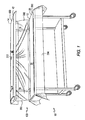
- FIG. 1 is a perspective view of a table covered with the surgical drape.
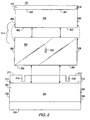
- FIG. 2 is an exploded view of the one-piece embodiment of the surgical drape showing the attachment points of the three sections.
- In accordance with the present invention, a drape for a multiple-tiered hospital surface is comprised of a generally rectangular bottom sheet affixed to a clear middle sheet which is affixed to a generally rectangular top sheet and the means for continuous joining of said bottom, middle, and top sheet in a one piece embodiment and the means for applying said drape to a hospital surface.
- A description of the preferred embodiments of the present invention will now be presented with reference to FIGS. 1 and 2.
- In a preferred embodiment the drape is for covering what is known in the art as a "back table", which will be shown as a table 10 having a
bottom tier 12 and anupper tier 14, the twotiers rear posts drape 100 is shown in place in FIG. 1 covering such a table 10. - Two embodiments of the present invention are provided: a one-
piece 100 and a two-piece drape. Thedrape 100 is shown in exploded view in FIG. 2. - The
bottom section 200 comprises a generally rectangular sheet of liquid impervious material such as are known for use in the art. The liquid impervious nature is important to prevent any spillage or leakage from seeping through the sheet, contacting the non-sterile table surface, and wicking back up through the sheet, which then would be contaminated. In a particular embodiment the material comprises a plastic such as polyethylene, typically colored blue for this application, although this is not intended to be limiting. The sheet has a pair ofcutouts rear edge 212 for admitting thetable posts cutouts bottom tier 12 surface. The width and depth of thebottom section 200 are dimensioned for side and front draping along theside front edges 204, respectively. - Affixed atop the
bottom section 200 is another rectangular piece of flexible material, bonded to thebottom section 200 to form a laminate. Thissurface section 202 is dimensioned generally to conform to the top of thebottom tier 12, is made of a cloth-like material such as a non-woven fabric having a wood pulp base (e.g., Dexter® made by DuPont). - A
top section 400 also comprises a generally rectangular sheet of liquid impervious material, for example, polyethylene, again typically colored blue. Thetop section 400 is also laminated with a non-woven cloth-like material such as Dexter®. Therear edge 404 is turned upward and affixed along the sides to form atop flap 410 which serves as a cuff for assisting in placing the drape, as will be described in the following. - A
clear section 300 is affixed along itsbottom edge 304 adjacent the bottom section's backedge 214 just forward of thecutouts Clear section 300 is also affixed along itstop edge 302 to the top section'sfront edge 402, and itsside edges corresponding side edges upper drape portion 400 from therear edge 212 to a location per side in spaced relation from thefront edge 402 commensurate with the width of theupper tier 14. Thus theupper portion 302 of theclear section 300 forms a flap extending along the front edge of thedrape 100 for fitting to anupper tier 14 and tucking thereunder. - Preferably the
clear section 300 is also made of a liquid impervious material, such as but not limited to, polyethylene which has sufficient translucence to permit visualization of table surface there through. - In order to secure the flap onto the
upper tier 14, further affixing means are also provided. In a preferred embodiment apiece 310 of one part of a hook-and-loop type fastener (Velcro®) is affixed to a back side of theclear section 300 generally in line with the inward ends of the side-affixing locations. This piece is for mating with acorresponding piece 312 affixed beneath and generally adjacent the rear edge of thetop tier 14. When mated, the fastener pieces hold the central part of the clear section up and out of the way of thebottom tier 12. - The drape can be made in a two-piece embodiment (not shown), where the
bottom section 200 and theclear section 300 are not affixed together; otherwise, the sections are constructed substantially the same as for thedrape 100, with theclear section 300 being longer to permit a draping behind thebottom tier 12. - The
drape 100 as described above is made by forming the threesections - The
drape 100 is used by removing it from a protective covering, placing it in the center of the bottom tier of the instrument table 12 and unfolding thedrape 100 from the middle to each side of the table 12 so that the sterile side of thebottom section 200 is positioned upward. The exposed front part of thedrape 204 is then brought forward to cover the front edge of thebottom tier 12. Moving to the rear of the table 10 the remaining exposed drape is brought back so that thecutouts drape 202 correspond to theposts top tier 14. The drape will now have cuffedflap areas 410 exposed on both ends. Theupper drape section 400 is then raised up by a person on either side of the instrument table 10 inserting hands into theflap areas 410, lifting the drape and placingupper drape section 400 on top tier of instrument table 14 withback overhang 404 draping over the rear portion of top tier of instrument table 14. Lifting theupper drape section 400 also brings the upper portion of theclear section 300 upward. To finish applyingdrape 100 middle section ofdrape 300 is affixed up and away from the bottom piece ofdrape 200 by means of hook-and-loop type fasteners middle section 310 are joined to theircorresponding mates 312 on the underside of the top tier of the instrument table 14, and the remaining portion of theclear section 300 is arrayed along the rear of the table. - It may be appreciated by one skilled in the art that additional embodiments may be contemplated, including additional drapes designed for tables having multiple tiers and supports thereof.
- Accordingly the reader will see that the drape for the multiple-tiered hospital surface can be used to quickly and conveniently create a sterile field. Furthermore, the multiple-tiered drape has the additional advantages in that:
- It permits the draping to be done by sterile or non-sterile personnel;
- It allows for instrument trays to be seen on both levels as well as from the back of the table;
- It provides a superior surface upon which multiple trays can be placed;
- It provides a custom fit to the surface it is covering so as to keep the instrument trays in place.
- Although the description above contains many specificities, these should not be construed as limiting the scope of the invention. Rather, as merely providing illustrations of the presently preferred embodiments of this invention currently in use in over fifty hospital operating rooms in the United States. Certain terms have been used for brevity, clarity, and understanding, but no unnecessary limitations are to be implied therefrom beyond the requirements of the prior art, because such words are used for description purposes herein and intended to be broadly construed. Moreover, the embodiments of the apparatus illustrated and described here are by way of example, and the scope of the invention is not limited to the exact details of construction.
- Thus, the scope of the invention should be determined by the appended claims rather than by the examples given.
Claims (9)
- A drape for a table (10) in an operating room, the table (10) having a lower tier (12) and an upper tier (14), the lower tier (12) having a lower tier surface, the upper tier (14) having an upper tier surface and an opposed underside surface disposed at least partially over the lower tier surface, the drape (100) comprising:a bottom section (200) having a top surface operable to cover the lower tier surface to define a sterile lower tier surface;a top section (400) having a front edge (402) and operable to cover the upper tier surface to define a sterile upper tier surface;a middle section (300) having a bottom edge (304) and a top edge (302);a side edge (306, 308) of the middle section (300) being attached to a side edge (406, 408) of the top section (400) to form a flap operable to fit over at least a portion of the upper tier (14);wherein the drape is formed either as a one-piece drape (100) or, alternatively, as a two-piece drape;
the one-piece drape (100) having the bottom edge (304) of the middle section (300) attached to the top surface of the bottom section (200) and having the top edge (302) of the middle section (300) attached to the front edge (402) of the top section (400) for isolating the sterile lower tier surface from the underside surface;
the two-piece drape having the bottom edge of the middle section abutting the top surface of the bottom section and having the top edge of the middle section attached to the front edge of the top section for isolating the sterile lower tier surface from the underside surface. - The drape of claim 1, further comprising a means for holding a central portion of the middle section (300) away from the sterile lower tier surface.
- The drape of at least one of the preceding claims, further comprising a fastener (310) attached to a back surface of the middle section (300).
- The drape of claim 3, wherein the fastener (310) comprises a hook and loop fastener.
- The drape of at least one of the preceding claims, wherein the middle section (300) comprises a clear material.
- The drape of at least one of the preceding claims, further comprising a flap (410) formed on a rear portion of the top section (400).
- The drape of at least one of the preceding claims, wherein the table (10) has a post (16, 18) between the upper tier (14) and the lower tier (12), the drape (100) further comprising a cutout (216, 218) formed in a rear portion of the bottom section (200) and operable to fit around the post (16, 18).
- A draped table for an operating room, the draped table (10) comprising:a table lower tier (12) having a lower tier surface;a table upper tier (14) having an upper tier surface and an opposed underside surface;a structure connecting the table lower tier (12) and the table upper tier (14) so that the underside surface is disposed at least partially above the table lower tier surface; anda drape (100) according to at least one of the preceding claims with the top surface of the bottom section disposed over the lower tier surface to define the sterile lower tier surface and the top section disposed over the upper tier surface to define the sterile upper tier surface and the middle section disposed under the upper tier underside surface for isolating the sterile lower tier surface from the underside surface.
- The draped table of claim 8, wherein the structure comprises a post (16, 18) connecting a rear portion of the upper tier (14) and a rear portion of the lower tier (12), and the drape (100) further comprising a cutout (216, 218) in a rear portion of the bottom section (200) for admitting the post (16, 18), the post (16, 18) and the cutout (216, 218) being isolated from the sterile lower tier surface by the middle section (300).
Priority Applications (1)
| Application Number | Priority Date | Filing Date | Title |
|---|---|---|---|
| AT99963054T ATE341283T1 (en) | 1999-12-09 | 1999-12-09 | COVER FOR MULTI-STORY STERILE HOSPITAL SURFACES |
Applications Claiming Priority (2)
| Application Number | Priority Date | Filing Date | Title |
|---|---|---|---|
| US09/160,812 US6019102A (en) | 1998-09-25 | 1998-09-25 | Drape for multiple-tiered sterile hospital surface and associate methods |
| PCT/US1999/029210 WO2001041665A1 (en) | 1998-09-25 | 1999-12-09 | Drape for multiple-tiered sterile hospital surface |
Publications (4)
| Publication Number | Publication Date |
|---|---|
| EP1237494A1 EP1237494A1 (en) | 2002-09-11 |
| EP1237494A4 EP1237494A4 (en) | 2004-03-17 |
| EP1237494B1 EP1237494B1 (en) | 2006-10-04 |
| EP1237494B9 true EP1237494B9 (en) | 2007-02-14 |
Family
ID=26795934
Family Applications (1)
| Application Number | Title | Priority Date | Filing Date |
|---|---|---|---|
| EP99963054A Expired - Lifetime EP1237494B9 (en) | 1998-09-25 | 1999-12-09 | Drape for multiple-tiered sterile hospital surface |
Country Status (9)
| Country | Link |
|---|---|
| US (1) | US6019102A (en) |
| EP (1) | EP1237494B9 (en) |
| JP (1) | JP3640640B2 (en) |
| AU (1) | AU767487B2 (en) |
| CA (1) | CA2382946C (en) |
| DE (1) | DE69933481T2 (en) |
| DK (1) | DK1237494T3 (en) |
| ES (1) | ES2274652T3 (en) |
| WO (1) | WO2001041665A1 (en) |
Cited By (1)
| Publication number | Priority date | Publication date | Assignee | Title |
|---|---|---|---|---|
| US10350020B2 (en) | 2015-05-01 | 2019-07-16 | Chris Geiger | Medical tray assembly |
Families Citing this family (17)
| Publication number | Priority date | Publication date | Assignee | Title |
|---|---|---|---|---|
| US6497233B1 (en) | 2001-03-13 | 2002-12-24 | Deangelis Luciano S. | One-piece sterile drape for use on surgical instrument carts |
| US6823805B2 (en) | 2002-03-05 | 2004-11-30 | Dan L. Becker | Table for operating room |
| US20050072434A1 (en) * | 2003-02-28 | 2005-04-07 | Becker Dan L. | Table for operating room |
| USD602300S1 (en) | 2008-01-07 | 2009-10-20 | Cynthia Sue Jeska | Bed sheet |
| CN102596089A (en) | 2009-08-07 | 2012-07-18 | 美联实业有限公司 | Medical drape |
| US8459265B2 (en) * | 2010-04-12 | 2013-06-11 | Variamed, Llc | Unitary structured multi-tier drape |
| US8424532B2 (en) | 2010-07-26 | 2013-04-23 | Medline Industries, Inc. | Cranial surgical drape |
| US9278166B2 (en) | 2011-03-02 | 2016-03-08 | Medline Industries, Inc. | Method and apparatus pertaining to a medical drape having a suction port |
| US10568710B2 (en) | 2012-01-13 | 2020-02-25 | Variamed, Llc | Spinal procedure patient drape |
| US9737363B2 (en) | 2012-08-10 | 2017-08-22 | Avent, Inc. | Sterile drape for two tiered hospital instrument table |
| US10070924B2 (en) * | 2013-03-13 | 2018-09-11 | Medline Industries, Inc. | Apparatus and method pertaining to a multi-tier back-table drape |
| US9895201B2 (en) * | 2015-02-27 | 2018-02-20 | Flex Operating Room, Llc | Cantilever organizational rack system for supporting surgical instrumentation |
| US10271917B2 (en) * | 2015-02-27 | 2019-04-30 | Flex Operating Room, Llc | Surgical tray efficiency system and related methods |
| US11020199B2 (en) | 2016-03-14 | 2021-06-01 | Medline Industries, Inc. | Surgical drape |
| USD884905S1 (en) | 2018-01-18 | 2020-05-19 | Medline Industries, Inc. | Surgical C-section drape with tunnel |
| US11246675B2 (en) | 2018-01-18 | 2022-02-15 | Medline Industries, Lp | Surgical C-section drape with tunnel |
| US11883212B2 (en) * | 2020-11-20 | 2024-01-30 | Variamed Llc | Surgical instrument table and drape therefor |
Family Cites Families (11)
| Publication number | Priority date | Publication date | Assignee | Title |
|---|---|---|---|---|
| FR745004A (en) * | 1933-05-01 | |||
| US3902484A (en) * | 1972-02-07 | 1975-09-02 | Kimberly Clark Co | Disposable surgical drape |
| US3911912A (en) * | 1974-10-15 | 1975-10-14 | Kimberly Clark Co | Combination surgical drape |
| US4873997A (en) * | 1988-04-25 | 1989-10-17 | Scherer Healthcare Ltd. | Surgical drape |
| DE3913617A1 (en) * | 1989-04-25 | 1990-10-31 | Johnson & Johnson Medical | Sterile cover for X=ray image intensifier - is disposable integral piece foldable for ease of storage |
| US5151314A (en) * | 1991-01-31 | 1992-09-29 | Johnson & Johnson Medical, Inc. | Three-layer laminated panel |
| US5170804A (en) * | 1991-02-14 | 1992-12-15 | Glassman Jacob A | Mayo-stand disposable drape |
| US5560974A (en) * | 1991-03-22 | 1996-10-01 | Kappler Safety Group, Inc. | Breathable non-woven composite barrier fabric and fabrication process |
| US5411036A (en) * | 1992-11-18 | 1995-05-02 | Wilkes; Kenneth R. | Mayo stand cover |
| US5592952A (en) * | 1995-08-18 | 1997-01-14 | Bohn; William W. | Infection control surgical drape and method of making surgical incision |
| US5766737A (en) * | 1996-07-23 | 1998-06-16 | Fiberweb North America, Inc. | Nonwoven fabrics having differential aesthetic properties and processes for producing the same |
-
1998
- 1998-09-25 US US09/160,812 patent/US6019102A/en not_active Expired - Lifetime
-
1999
- 1999-12-09 JP JP2001542838A patent/JP3640640B2/en not_active Expired - Fee Related
- 1999-12-09 CA CA002382946A patent/CA2382946C/en not_active Expired - Fee Related
- 1999-12-09 AU AU19371/00A patent/AU767487B2/en not_active Ceased
- 1999-12-09 DE DE69933481T patent/DE69933481T2/en not_active Expired - Lifetime
- 1999-12-09 EP EP99963054A patent/EP1237494B9/en not_active Expired - Lifetime
- 1999-12-09 DK DK99963054T patent/DK1237494T3/en active
- 1999-12-09 WO PCT/US1999/029210 patent/WO2001041665A1/en not_active Ceased
- 1999-12-09 ES ES99963054T patent/ES2274652T3/en not_active Expired - Lifetime
Cited By (3)
| Publication number | Priority date | Publication date | Assignee | Title |
|---|---|---|---|---|
| US10350020B2 (en) | 2015-05-01 | 2019-07-16 | Chris Geiger | Medical tray assembly |
| US10952805B2 (en) | 2015-05-01 | 2021-03-23 | Chris Geiger | Medical tray assembly |
| US11478323B2 (en) | 2015-05-01 | 2022-10-25 | Chris Geiger | Medical tray assembly |
Also Published As
| Publication number | Publication date |
|---|---|
| US6019102A (en) | 2000-02-01 |
| EP1237494A4 (en) | 2004-03-17 |
| CA2382946A1 (en) | 2001-06-14 |
| DK1237494T3 (en) | 2007-02-05 |
| AU1937100A (en) | 2001-06-18 |
| EP1237494A1 (en) | 2002-09-11 |
| JP2003515427A (en) | 2003-05-07 |
| JP3640640B2 (en) | 2005-04-20 |
| CA2382946C (en) | 2005-12-27 |
| DE69933481D1 (en) | 2006-11-16 |
| ES2274652T3 (en) | 2007-05-16 |
| DE69933481T2 (en) | 2007-03-15 |
| WO2001041665A1 (en) | 2001-06-14 |
| AU767487B2 (en) | 2003-11-13 |
| EP1237494B1 (en) | 2006-10-04 |
Similar Documents
| Publication | Publication Date | Title |
|---|---|---|
| EP1237494B9 (en) | Drape for multiple-tiered sterile hospital surface | |
| US7891359B2 (en) | Surgical drape | |
| EP0280816B1 (en) | Surgical isolation drape | |
| EP0043839B1 (en) | Surgical drape system | |
| US4957120A (en) | Surgical drape with extremity pouch | |
| US6497233B1 (en) | One-piece sterile drape for use on surgical instrument carts | |
| US5170804A (en) | Mayo-stand disposable drape | |
| US5042507A (en) | Surgical drape for ophthalmic procedures | |
| US6129085A (en) | Craniotomy drape | |
| US5038798A (en) | Opthalmic drape with fluid collection pouch | |
| US7104201B2 (en) | Sterile surgical table cover | |
| CA1038715A (en) | Self-adhesive surgical apparel | |
| US5778891A (en) | Surgical drape | |
| US6749063B2 (en) | Endoscope transportation device | |
| US20030233964A1 (en) | Sterile surgical table cover | |
| US5592952A (en) | Infection control surgical drape and method of making surgical incision | |
| US5522403A (en) | Splash shield | |
| US20210307856A1 (en) | Surgical Drape | |
| US20080053462A1 (en) | Surgical drape with convective heat therapy device | |
| EP0185002B1 (en) | An arrangement in surgical drapes | |
| EP3698748B1 (en) | Surgical table disposable base cover | |
| JPS6121058Y2 (en) | ||
| EP0845246A1 (en) | Surgical drape | |
| WO1996015689A1 (en) | Protective device for use with minor surgical operations | |
| AU6774181A (en) | Surgical drape system |
Legal Events
| Date | Code | Title | Description |
|---|---|---|---|
| PUAI | Public reference made under article 153(3) epc to a published international application that has entered the european phase |
Free format text: ORIGINAL CODE: 0009012 |
|
| 17P | Request for examination filed |
Effective date: 20020618 |
|
| AK | Designated contracting states |
Kind code of ref document: A1 Designated state(s): AT BE CH CY DE DK ES FI FR GB GR IE IT LI LU MC NL PT SE |
|
| AX | Request for extension of the european patent |
Free format text: AL;LT;LV;MK;RO;SI |
|
| A4 | Supplementary search report drawn up and despatched |
Effective date: 20040203 |
|
| RIC1 | Information provided on ipc code assigned before grant |
Ipc: 7A 61B 19/08 B Ipc: 7A 61B 19/00 A |
|
| 17Q | First examination report despatched |
Effective date: 20050316 |
|
| GRAP | Despatch of communication of intention to grant a patent |
Free format text: ORIGINAL CODE: EPIDOSNIGR1 |
|
| GRAS | Grant fee paid |
Free format text: ORIGINAL CODE: EPIDOSNIGR3 |
|
| GRAA | (expected) grant |
Free format text: ORIGINAL CODE: 0009210 |
|
| AK | Designated contracting states |
Kind code of ref document: B1 Designated state(s): AT BE CH CY DE DK ES FI FR GB GR IE IT LI LU MC NL PT SE |
|
| PG25 | Lapsed in a contracting state [announced via postgrant information from national office to epo] |
Ref country code: LI Free format text: LAPSE BECAUSE OF FAILURE TO SUBMIT A TRANSLATION OF THE DESCRIPTION OR TO PAY THE FEE WITHIN THE PRESCRIBED TIME-LIMIT Effective date: 20061004 Ref country code: FI Free format text: LAPSE BECAUSE OF FAILURE TO SUBMIT A TRANSLATION OF THE DESCRIPTION OR TO PAY THE FEE WITHIN THE PRESCRIBED TIME-LIMIT Effective date: 20061004 Ref country code: CH Free format text: LAPSE BECAUSE OF FAILURE TO SUBMIT A TRANSLATION OF THE DESCRIPTION OR TO PAY THE FEE WITHIN THE PRESCRIBED TIME-LIMIT Effective date: 20061004 Ref country code: BE Free format text: LAPSE BECAUSE OF FAILURE TO SUBMIT A TRANSLATION OF THE DESCRIPTION OR TO PAY THE FEE WITHIN THE PRESCRIBED TIME-LIMIT Effective date: 20061004 Ref country code: AT Free format text: LAPSE BECAUSE OF FAILURE TO SUBMIT A TRANSLATION OF THE DESCRIPTION OR TO PAY THE FEE WITHIN THE PRESCRIBED TIME-LIMIT Effective date: 20061004 |
|
| REG | Reference to a national code |
Ref country code: GB Ref legal event code: FG4D |
|
| REG | Reference to a national code |
Ref country code: CH Ref legal event code: EP |
|
| REG | Reference to a national code |
Ref country code: IE Ref legal event code: FG4D |
|
| REF | Corresponds to: |
Ref document number: 69933481 Country of ref document: DE Date of ref document: 20061116 Kind code of ref document: P |
|
| PG25 | Lapsed in a contracting state [announced via postgrant information from national office to epo] |
Ref country code: IE Free format text: LAPSE BECAUSE OF NON-PAYMENT OF DUE FEES Effective date: 20061211 |
|
| PG25 | Lapsed in a contracting state [announced via postgrant information from national office to epo] |
Ref country code: MC Free format text: LAPSE BECAUSE OF NON-PAYMENT OF DUE FEES Effective date: 20061231 |
|
| PGFP | Annual fee paid to national office [announced via postgrant information from national office to epo] |
Ref country code: IT Payment date: 20061231 Year of fee payment: 8 |
|
| PG25 | Lapsed in a contracting state [announced via postgrant information from national office to epo] |
Ref country code: SE Free format text: LAPSE BECAUSE OF FAILURE TO SUBMIT A TRANSLATION OF THE DESCRIPTION OR TO PAY THE FEE WITHIN THE PRESCRIBED TIME-LIMIT Effective date: 20070104 |
|
| REG | Reference to a national code |
Ref country code: DK Ref legal event code: T3 |
|
| PG25 | Lapsed in a contracting state [announced via postgrant information from national office to epo] |
Ref country code: PT Free format text: LAPSE BECAUSE OF FAILURE TO SUBMIT A TRANSLATION OF THE DESCRIPTION OR TO PAY THE FEE WITHIN THE PRESCRIBED TIME-LIMIT Effective date: 20070316 |
|
| REG | Reference to a national code |
Ref country code: CH Ref legal event code: PL |
|
| ET | Fr: translation filed | ||
| REG | Reference to a national code |
Ref country code: ES Ref legal event code: FG2A Ref document number: 2274652 Country of ref document: ES Kind code of ref document: T3 |
|
| PLBE | No opposition filed within time limit |
Free format text: ORIGINAL CODE: 0009261 |
|
| STAA | Information on the status of an ep patent application or granted ep patent |
Free format text: STATUS: NO OPPOSITION FILED WITHIN TIME LIMIT |
|
| 26N | No opposition filed |
Effective date: 20070705 |
|
| PG25 | Lapsed in a contracting state [announced via postgrant information from national office to epo] |
Ref country code: GR Free format text: LAPSE BECAUSE OF FAILURE TO SUBMIT A TRANSLATION OF THE DESCRIPTION OR TO PAY THE FEE WITHIN THE PRESCRIBED TIME-LIMIT Effective date: 20070105 |
|
| PG25 | Lapsed in a contracting state [announced via postgrant information from national office to epo] |
Ref country code: LU Free format text: LAPSE BECAUSE OF NON-PAYMENT OF DUE FEES Effective date: 20061209 |
|
| PG25 | Lapsed in a contracting state [announced via postgrant information from national office to epo] |
Ref country code: CY Free format text: LAPSE BECAUSE OF FAILURE TO SUBMIT A TRANSLATION OF THE DESCRIPTION OR TO PAY THE FEE WITHIN THE PRESCRIBED TIME-LIMIT Effective date: 20061004 |
|
| PG25 | Lapsed in a contracting state [announced via postgrant information from national office to epo] |
Ref country code: IT Free format text: LAPSE BECAUSE OF NON-PAYMENT OF DUE FEES Effective date: 20071209 |
|
| PGFP | Annual fee paid to national office [announced via postgrant information from national office to epo] |
Ref country code: DK Payment date: 20131126 Year of fee payment: 15 |
|
| REG | Reference to a national code |
Ref country code: GB Ref legal event code: S72Z Free format text: CLAIM LODGED; CLAIM FOR REVOCATION LODGED AT THE PATENTS COURT ON 12 NOVEMBER 2013 (HC13 B04876) |
|
| PGFP | Annual fee paid to national office [announced via postgrant information from national office to epo] |
Ref country code: GB Payment date: 20131126 Year of fee payment: 15 |
|
| REG | Reference to a national code |
Ref country code: GB Ref legal event code: S29 Free format text: OFFER FILED; APPLICATION FILED ON 30 DECEMBER 2013 |
|
| PGFP | Annual fee paid to national office [announced via postgrant information from national office to epo] |
Ref country code: NL Payment date: 20131206 Year of fee payment: 15 Ref country code: FR Payment date: 20131126 Year of fee payment: 15 Ref country code: ES Payment date: 20131220 Year of fee payment: 15 |
|
| REG | Reference to a national code |
Ref country code: GB Ref legal event code: CORR Free format text: THE ENTRY FOR PATENT EP1237494 WHICH WAS ADVERTISED IN PATENTS JOURNAL 6507 DATED 5TH FEBRUARY 2014 AS AN SECTION 29 OFFER TO SURRENDER, HAD THE INCORRECT PROPRIETOR'S DETAILS AS DAN L BECKER. THE CORRECT PROPRIETOR NAME IS OR SPECIFIC, INC. |
|
| REG | Reference to a national code |
Ref country code: GB Ref legal event code: 732E Free format text: REGISTERED BETWEEN 20140327 AND 20140402 |
|
| REG | Reference to a national code |
Ref country code: DE Ref legal event code: R082 Ref document number: 69933481 Country of ref document: DE Representative=s name: GRUENECKER, KINKELDEY, STOCKMAIR & SCHWANHAEUS, DE |
|
| PGFP | Annual fee paid to national office [announced via postgrant information from national office to epo] |
Ref country code: DE Payment date: 20131230 Year of fee payment: 15 |
|
| REG | Reference to a national code |
Ref country code: DE Ref legal event code: R082 Ref document number: 69933481 Country of ref document: DE Representative=s name: GRUENECKER, KINKELDEY, STOCKMAIR & SCHWANHAEUS, DE Effective date: 20140429 Ref country code: DE Ref legal event code: R081 Ref document number: 69933481 Country of ref document: DE Owner name: OR SPECIFIC, INC., ORLANDO, US Free format text: FORMER OWNER: BECKER, DAN L., ORLANDO, FLA., US Effective date: 20140429 Ref country code: DE Ref legal event code: R081 Ref document number: 69933481 Country of ref document: DE Owner name: OR SPECIFIC, INC., US Free format text: FORMER OWNER: BECKER, DAN L., ORLANDO, US Effective date: 20140429 |
|
| REG | Reference to a national code |
Ref country code: DE Ref legal event code: R231 Ref document number: 69933481 Country of ref document: DE |
|
| REG | Reference to a national code |
Ref country code: ES Ref legal event code: PC2A Owner name: OR SPECIFIC, INC. Effective date: 20140805 |
|
| REG | Reference to a national code |
Ref country code: NL Ref legal event code: VD4 Effective date: 20061004 Ref country code: NL Ref legal event code: SD Effective date: 20140801 |
|
| REG | Reference to a national code |
Ref country code: ES Ref legal event code: FD2A Effective date: 20140818 Ref country code: DK Ref legal event code: EAP Effective date: 20140811 |
|
| REG | Reference to a national code |
Ref country code: FR Ref legal event code: TP Owner name: OR SPECIFIC INC., US Effective date: 20140804 Ref country code: FR Ref legal event code: RT Effective date: 20140804 |
|
| PG25 | Lapsed in a contracting state [announced via postgrant information from national office to epo] |
Ref country code: NL Free format text: LAPSE BECAUSE OF THE APPLICANT RENOUNCES Effective date: 20061004 Ref country code: DE Free format text: LAPSE BECAUSE OF THE APPLICANT RENOUNCES Effective date: 20140801 |
|
| PG25 | Lapsed in a contracting state [announced via postgrant information from national office to epo] |
Ref country code: ES Free format text: THE PATENT HAS BEEN ANNULLED BY A DECISION OF A NATIONAL AUTHORITY Effective date: 20140806 |
|
| PG25 | Lapsed in a contracting state [announced via postgrant information from national office to epo] |
Ref country code: DK Free format text: LAPSE BECAUSE OF THE APPLICANT RENOUNCES Effective date: 20140811 |
|
| REG | Reference to a national code |
Ref country code: GB Ref legal event code: S72Z Free format text: CLAIM NO. HP13 B04876) THE CLAIM FOR REVOCATION WAS DISCONTINUED AND THE PATENT WAS REVOKED. |
|
| PG25 | Lapsed in a contracting state [announced via postgrant information from national office to epo] |
Ref country code: GB Free format text: THE PATENT HAS BEEN ANNULLED BY A DECISION OF A NATIONAL AUTHORITY Effective date: 20140930 |
|
| REG | Reference to a national code |
Ref country code: FR Ref legal event code: ST Effective date: 20150831 |
|
| PG25 | Lapsed in a contracting state [announced via postgrant information from national office to epo] |
Ref country code: FR Free format text: LAPSE BECAUSE OF NON-PAYMENT OF DUE FEES Effective date: 20141231 |
|
| PG25 | Lapsed in a contracting state [announced via postgrant information from national office to epo] |
Ref country code: NL Free format text: THE PATENT HAS BEEN ANNULLED BY A DECISION OF A NATIONAL AUTHORITY Effective date: 20061004 |